

Page 1

CHAPTER 6. MAINTENANCE AND INSPECTI ON
Most of maintenance of this radar should be referred to qualifie d personnel. If
radar has an y problem, co n tact your dealer and tell us that problem.
!
WARNING
There are high voltage circuits inside of this radar.
Do not attempt to open the rear cover of display
un it or di sassemble i nternal parts. W hen you op en
the radome, power must be off.
Even power switch is OFF, this radar is still supplied powe r ins ide .
The foll owing table shows th e maintenan ce b y user. P l ea se c heck peri od i cal l y .
Tab . 6-1 Ma int enan ce
Inspection Interval Inspection Item Method of Inspection and Maintenance
3-6 months Rust a n d l oose ness
in scanner unit
Display screen of
LCD display
6-12 months Grease* application
to antenna drive
gear
Check for contact
of connectors
Antenn a mo to r
brush(RA42C)
Check whether the scanner’s fitt ing bolt s are
corroded or less.
Clean filter and LCD screen surfaces with a
soft and wet cloth.
Apply an even coating of grease* to the entire
surface of the antenna drive gear with a spatula or brus h .
Check whether connectors are contacted
properly. If any connector is improperly conta ct ed or sta i ned, corr ect i t by using a cont a ct
restoring chemical agent or by polishing or
replace with a new one if necessary.
Check the length of brushes. I f the length is
under 6mm, change them to new one.
*: Use grease for plastics for RA40C/41C. If you use other type of grease(not for plastics),
it may break antenna
Concerning Consumable
The radar uses consumable as listed below that require periodic replacement.
(1) Mag netron
This part i s mount ed in the scan ner un it. If distan t echo im ag es h ave
become l ess visible, th e mag netro n p r oba bly may h a ve deg r aded . In such a
case, rep lac e it. Co n s ult yo ur d istributor f o r repl ac em ent o f this part.
Period of the replacement : 3000hour(typ.) (500hour guarantee)
(2) LC D ba ck-li ght
This part is mounted in the display unit. I f the display scree n is extremely dar k and its illumination cannot be corre cte d by a djusting brightness, the LCD back-light may be faulty or may have burnt out. In such a
case, rep lac e it. Co n s ult yo ur d istributor f o r repl ac em ent o f this part.
Period of the replacement : 15000hour(typ.) (1000hour at 0•)
79
Page 2
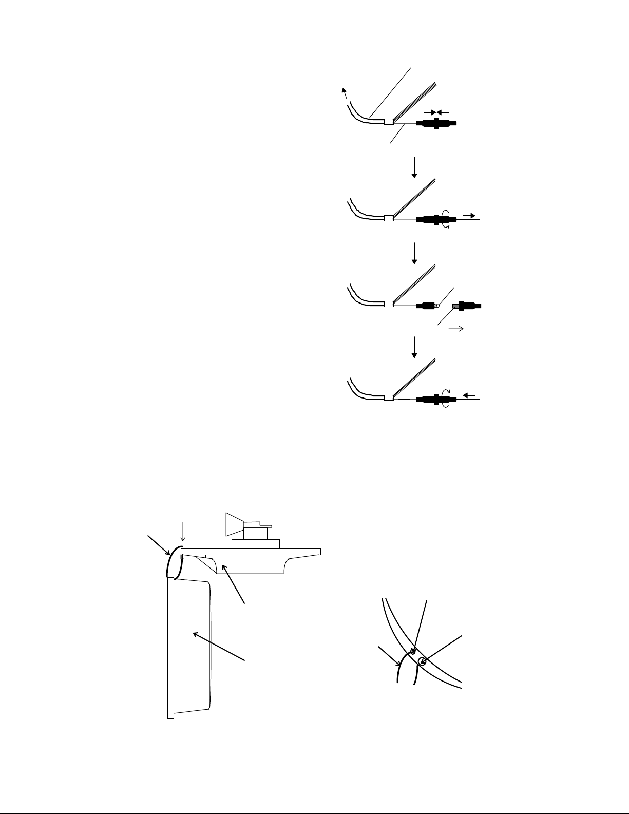
(3) Fuse
The fuse is built in
the power supply cable.
I f the fuse appe ar s to be
blow n, check the fu se. I f
blown, replace it
following the procedure
shown in Fig.6-2.
To display unit
Wire(White)
Power supply cable
Push
Turn countercl ock wi se
and pull
Spring
Fuse
Replace new fuse
Push and turn clockwise
Fig. 6-2 Method for replacing fuse
Note : Before mai ntenance of scanner , you ca n hang a radome(u pper ) using cord
through hole as follows.
A
Cord
A: Top view
Radome(bottom)
Hole
Cord
Radome(Upper)
Fig. 6-3 Method for replacing fuse
80
Fixing screw
 Loading...