

Koden MDC-7900P series, MDC-7912P, MDC-7000P series, MDC-7925P, MDC-7012P Installation Manual
...Page 1

Page 2

Page 3

MDC-7000P/7900P Series Revision History
MDC-7000P/7900P Series Installation Manual
Doc No: 0092669006
Document Revision History
No. Doc. No.-Rev. No. Date Revised
(Y/M/D)
0 0092669006-05 2015/10/16 First edition
1 0092669006-05A 2016/03/08
2 0092669006-05B 2016/04/08 Chapter 4
3 0092669006-05C 2016/06/08 Revised document code of cover, Chapter 3, Chapter 5
4 0092669006-05D 2016/11/29 4.5.5 SEA OFFSET Addition, Correction
5 0092669006-05E 2016/12/13 Correction
6
4.2.4 ANT HEIGHT and 4.2.12 FERRY MENU Addition,
Corrected Chapter 4, Wording
Revised Content
7
8
9
10
Document No. Revised Version Norm
When part of the document needs to be revised, the document has advanced revision number.
The document No. is indicated at the lower right side on the cover and at the left or right side of the
footer region of each page.
© 2015-2016 Koden Electronics Co., Ltd. All rights reserved.
No part of this publication may be reproduced, transmitted, translated in any from by any means
without the written permission of Koden Electronics Co., Ltd. The technical descriptions contained in
this publication are subject to change without notice. Koden assumes no responsibility for any errors,
incidental or consequential damages caused by misinterpretation of the descriptions contained in this
publication.
0092669006-05E i
Page 4

A table of content MDC-7000P/7900P Series
A table of content
Document Revision History .......................................................................................... i
A table of content ...................................................................................................................................... ii
Preface .................................................................................................................................................... 1
Precaution for operation .......................................................................................................................... 1
• Caution about rotating antenna: ......................................................................................................... 1
• Caution about health risks caused by radio wave: ............................................................................. 1
• Caution about dangerous internal high voltage in the device: ............................................................ 1
Precautions for maintenance ................................................................................................................... 2
• Caution against residual high voltage: ................................................................................................ 2
• Keep inboard power source “Off”: ....................................................................................................... 2
• Caution against the dust: .................................................................................................................... 2
• Measures against static electricity: ..................................................................................................... 2
• Break in procedure of stored radar: .................................................................................................... 2
Chapter 1 Prior to installation ................................................................................... 1-1
1.1 Installation precautions ........................................................................................................... 1-1
1.2 Unpacking of components ....................................................................................................... 1-1
1.3 Appearance verification of each unit and accessories ............................................................ 1-1
1.4 Selection of location for installation ......................................................................................... 1-1
1.4.1 Antenna Scanner unit ....................................................................................................... 1-2
1.4.2 Display unit and Operation unit ........................................................................................ 1-3
1.5 Cable wiring and interconnection ............................................................................................ 1-4
1.5.1 Antenna Scanner unit ....................................................................................................... 1-4
1.5.2 Display unit ....................................................................................................................... 1-4
Chapter 2 System configurations ............................................................................. 2-1
2.1 Standard configuration list ....................................................................................................... 2-1
2.2 Spare parts list ........................................................................................................................ 2-5
2.3 Installation material list ............................................................................................................ 2-5
2.4 Options .................................................................................................................................... 2-6
2.5 MDC-7912P/7925P series system configuration .................................................................... 2-7
2.6 MDC-7012P/7025P series system configuration .................................................................... 2-8
Chapter 3 Installation Method .................................................................................. 3-1
3.1 How to install the Antenna Scanner unit ................................................................................. 3-1
3.1.1 Installation of the Antenna Scanner unit ........................................................................... 3-2
3.1.2 Mounting antenna ............................................................................................................. 3-3
3.1.3 Installation of the connecting cable CW-845-xxM ............................................................ 3-4
3.1.3.1 MDC-7012P/7912P (Scanner unit RB808P) .............................................................. 3-4
3.1.3.2 MDC-7025P/7925P (Scanner unit RB809P) ............................................................ 3-10
ii 0092669006-05E
Page 5

MDC-7000P/7900P Series A table of content
3.2 Interconnection diagram of cable .......................................................................................... 3-16
3.3 Installation of the Display unit ............................................................................................... 3-17
3.3.1 Installation of MRD-108P ............................................................................................... 3-19
3.3.1.1 Tabletop mounting of MRD-108P ............................................................................ 3-19
3.3.1.2 Flush Mounting for MRD-108P ................................................................................ 3-21
3.3.2 Installation of Operation unit ........................................................................................... 3-22
3.3.2.1 Flush mounting the Operation unit........................................................................... 3-24
3.3.3 Installation of MRM-108P ............................................................................................... 3-25
3.4 Cable connection to a Display unit ....................................................................................... 3-26
3.4.1 Cable connection for MRD-108P .................................................................................... 3-26
3.4.2 Connecting an external monitor ..................................................................................... 3-27
3.4.3 Connecting a VDR or External monitor & Failure alarm output ..................................... 3-27
3.4.4 Connecting a Gyro converter unit or THD ...................................................................... 3-28
3.4.5 Connecting a Junctin box JB-35 to Gyro, OTHER and Inter-switch data ...................... 3-29
3.4.6 AIS cable connection ...................................................................................................... 3-30
3.4.7 Cable connection for EPFS and SDME or Log .............................................................. 3-31
3.4.8 Cable connection for inter-switch ................................................................................... 3-32
3.4.8.1 Cable connection instructions for cross-over, dual and independent connection ... 3-32
3.4.8.2 Cable connection for slave display used as a monitor ............................................ 3-33
Chapter 4 Setup after installation .............................................................................4-1
4.1 Display [MAINTENANCE] menu ............................................................................................. 4-2
4.1.1 How to change protected menu PASSWORD ................................................................. 4-2
4.2 STARTUP menu ..................................................................................................................... 4-2
4.2.1 Tune adjustment (TUNE) ................................................................................................. 4-2
4.2.2 Heading adjustment (HL OFFSET) .................................................................................. 4-3
4.2.3 Transmitting delay time adjustment (TX DELAY) ............................................................. 4-4
4.2.4 ANT HEIGHT .................................................................................................................... 4-4
4.2.5 ANT CABLE ...................................................................................................................... 4-5
4.2.6 Main Bang Suppression (MBS) ........................................................................................ 4-5
4.2.7 Setup SEA (STC) curve ................................................................................................... 4-6
4.2.8 Function key usage .......................................................................................................... 4-7
4.2.9 RANGE ENABLE .............................................................................................................. 4-8
4.2.10 TIMES ENABLE ............................................................................................................. 4-9
4.2.11 MONITOR SIZE ............................................................................................................ 4-10
4.2.12 FERRY MENU .............................................................................................................. 4-10
4.3 Setup I/O Interface ................................................................................................................ 4-11
4.3.1 Select Heading interfaces .............................................................................................. 4-12
4.3.2 Speed interfaces ............................................................................................................. 4-12
0092669006-05E iii
Page 6

A table of content MDC-7000P/7900P Series
4.3.2.1 Setup speed through water (STW) .......................................................................... 4-12
4.3.2.2 Select speed over ground (SOG) interface .............................................................. 4-13
4.3.3 Select POSITION interface ............................................................................................. 4-14
4.3.4 Select SET/DRIFT input ................................................................................................. 4-15
4.3.5 Setup TIME ..................................................................................................................... 4-15
4.3.6 Setup Output ................................................................................................................... 4-16
4.3.6.1 Alarm output ............................................................................................................. 4-16
4.3.6.2 Serial data output ..................................................................................................... 4-17
4.3.7 Limiting of type of signal to input port ............................................................................. 4-18
4.3.8 Changing formats of input/output ports of navigation devices, position and ship speed (IEC
61162). ..................................................................................................................................... 4-19
4.3.9 Setup KGC (GPS compass) ........................................................................................... 4-20
4.3.10 Setup JB-35 .................................................................................................................. 4-20
4.3.11 Serial monitor ................................................................................................................ 4-21
4.4 Setup SECTOR MUTE mode (Cannot use while transmitting) ............................................. 4-21
4.5 Setup PRESET ...................................................................................................................... 4-21
4.5.1 Setup RAIN MIN and MAX mode ................................................................................. 4-21
4.5.1.1 RAIN MIN (MAN and CFAR mode) .......................................................................... 4-21
4.5.1.2 RAIN MAX (MAN and CFAR mode) ........................................................................ 4-22
4.5.2 Setup SEA MIN and MAX mode ................................................................................... 4-23
4.5.2.1 SEA MIN (MAN and AUTO mode) ........................................................................... 4-23
4.5.2.2 SEA MAX (MAN and AUTO mode) .......................................................................... 4-24
4.5.3 Setup GAIN MIN and MAX mode ................................................................................. 4-25
4.5.3.1 GAIN MIN (MAN and AUTO mode) ......................................................................... 4-26
4.5.3.2 GAIN MAX (MAN and AUTO mode) ........................................................................ 4-27
4.5.4 Setup GAIN OFFSET mode ......................................................................................... 4-27
4.5.5 Setup SEA OFFSET mode ........................................................................................... 4-28
4.6 BACKUP of Setup data (Cannot be used while transmitting) ............................................... 4-28
4.6.1 Internal save of setup data ........................................................................................... 4-28
4.6.2 External save of setup data (Cannot be performed while transmitting)........................ 4-29
4.6.3 Parameter reset ............................................................................................................ 4-29
4.7 TOTAL Hour and TX Hour (Cannot use while transmitting) ................................................. 4-29
4.8 MENU Setup ......................................................................................................................... 4-30
4.9 MON (performance monitor) ................................................................................................. 4-31
4.9.1 Initial setup methods ..................................................................................................... 4-31
4.9.2 Confirmation methods for degradation of Antenna performance after operation ......... 4-32
4.10 System Program ................................................................................................................. 4-32
4.10.1 Version confirmation ................................................................................................... 4-32
iv 0092669006-05E
Page 7

MDC-7000P/7900P Series A table of content
4.10.2 How to update the system program ........................................................................... 4-33
Chapter 5 Troubleshooting and on board repair .......................................................5-1
5.1 Necessary information at the time of repair request ............................................................... 5-1
5.2 Provided self diagnostic facilities ............................................................................................ 5-1
5.2.1 Alarm display and how to cancel .................................................................................... 5-1
5.2.1.1 Alarm display list ........................................................................................................ 5-2
5.2.2 Operation note display .................................................................................................... 5-6
5.3 Malfunction diagnostics ........................................................................................................... 5-8
5.3.1 Malfunction detection step .............................................................................................. 5-8
5.3.2 Malfunction diagnostics flow chart .................................................................................. 5-9
5.3.2.1 Initial malfunction diagnostics .................................................................................... 5-9
5.3.2.2 Cannot turn on the power ........................................................................................ 5-10
5.3.2.3 No display ................................................................................................................ 5-11
5.3.2.4 No response from the Antenna unit ......................................................................... 5-12
5.3.2.5 Operation unit error .................................................................................................. 5-12
5.3.2.6 No radar echo .......................................................................................................... 5-14
5.3.2.7 Weak sensitivity of the radar echo ........................................................................... 5-15
5.3.2.8 Data such as heading, speed, latitude/longitude cannot be received ..................... 5-16
5.3.2.9 AIS ........................................................................................................................... 5-17
5.3.2.10 Antenna unit failure ................................................................................................ 5-18
5.4 On board repair ..................................................................................................................... 5-24
5.4.1 Replacement of fuse ..................................................................................................... 5-24
5.4.2 Replacement of Internal Battery ................................................................................... 5-25
Chapter 6 Maintenance ............................................................................................6-1
6.1 List of parts that have longevity .............................................................................................. 6-1
6.2 Regular service and cleaning up ............................................................................................ 6-2
6.2.1 Monthly inspection .......................................................................................................... 6-2
6.3 Method of exchanging the magnetron .................................................................................... 6-3
6.3.1 Magnetron replacement (RB808P) ................................................................................. 6-3
6.3.2 Magnetron replacement (RB809P) ................................................................................. 6-7
Chapter 7 Input/output data ......................................................................................7-1
7.1 Input data ................................................................................................................................ 7-1
7.1.1 Validity and integrity of input data .................................................................................. 7-1
7.1.2 Details of the data input format ...................................................................................... 7-1
7.2 Details of TT tracking data output ......................................................................................... 7-10
7.3 Details of the radar data output ............................................................................................ 7-11
7.4 Interface specification ........................................................................................................... 7-14
7.4.1 NAV and EPFS serial data input/output specification .................................................. 7-14
0092669006-05E v
Page 8

A table of content MDC-7000P/7900P Series
7.4.2 SDME serial data input/output specification ................................................................. 7-15
7.4.3 VDR (external monitor) and Alarm output signal specification ..................................... 7-16
7.4.3.1 Circuit for horizontal sync, vertical sync signal output ............................................. 7-16
7.4.3.2 Circuit for R, G, B video signal output ...................................................................... 7-16
7.4.3.3 Alarm contact specification ...................................................................................... 7-17
7.4.4 Serial data input/output specification (AIS) ................................................................... 7-17
7.4.5 Radar input/output signal specification ......................................................................... 7-18
7.4.6 Talker device code of the data output devices ............................................................. 7-19
7.4.7 Priority of talker device code ......................................................................................... 7-19
INTER CONNECTION DIAGRAM (RB808P) .............................................................................. A-1
INTER CONNECTION DIAGRAM (RB809P) .............................................................................. A-2
INTER CONNECTION DIAGRAM (MRD-108P/MRO-108P) ....................................................... A-3
INTER CONNECTION DIAGRAM (MRM-108P/MRO-108P) ....................................................... A-4
vi 0092669006-05E
Page 9

MDC-7000P/7900P Series Preface
Preface
[Precaution for safety issues]
Precaution for operation
• Caution about rotating antenna:
The radar antenna may start rotating without notice. Please keep away from the antenna for your
safety.
• Caution about health risks caused by radio wave:
Powerful electromagnetic waves are emitted from the antenna during operation. These waves can
cause ill effects on human bodies when exposed to continuous radiation.
International criteria
Though the international regulation states that the electromagnetic waves with a high-frequency
2
power density of not more than 100 W/m
do not have an ill effect on human bodies, medical
devices such as a pace makers are sensitive to electromagnetic waves with minute electric power
and their operation may become unstable. In any event, any person with such a device must keep
away from electromagnetic sources.
Specified power density and distance from antennas (according to the
provision as specified in IEC 60945)
Transmission power / antenna
length
12 kW / 4 feet antenna 2.01 m 2.84 m 6.34 m
12 kW / 6 feet antenna 2.38 m 3.37 m 7.54 m
12 kW / 9 feet antenna 2.83 m 4.01 m 8.96 m
25 kW / 4 feet antenna 2.89 m 4.09 m 9.15 m
25 kW / 6 feet antenna 3.44 m 4.86 m 10.88 m
25 kW / 9 feet antenna 4.09 m 5.78 m 12.93 m
100 W/m2 50W/m2 10 W/m2
• Caution about dangerous internal high voltage in the device:
High voltage that may cause risk of life is present in the Antenna unit and the Display unit of this radar.
This high voltage can remain in the circuit after the switch has been turned off. The high-voltage circuit
has a protective cover with a label “Caution against high voltage” so that no one will accidentally touch
it. Please ensure for your safety that the power switch is turned off and residual voltage in the capacitor
is discharged in a suitable manner when checking the inside of the antenna. Maintenance and
inspection should be conducted by qualified engineers only.
0092669006-05E 1
Page 10

Preface MDC-7000P/7900P Series
Precautions for maintenance
• Caution against residual high voltage:
Capacitors used in the Display unit and the modulator circuit of the transmission unit may keep high
voltage for several minutes even after turning off power. The maintenance and inspection of this part
should be performed at least 5 minutes after powering off or applying the appropriate measure to
discharge the residual electrical charge.
• Keep inboard power source “Off”:
An electric shock is possible if the power switch is accidentally turned on during the maintenance
operation. In order to prevent such an occurrence, please ensure to disconnect the power breaker of
the onboard power source and the device. Furthermore, it is recommended to post the word-of-caution
tag shown to be in a "working state" near the power switch of the device.
• Caution against the dust:
Dust can temporarily cause distress to the respiratory system. Take care not to inhale dust when
cleaning the interior of the device. It is recommended you wear a safety mask.
• Measures against static electricity:
Static electricity occurring from carpet on the floor of the cabin, clothes made of synthetic fiber etc., may
damage some electronic parts on the printed circuit board. Please work on the printed circuit board only
after taking measures against static electricity.
• Break in procedure of stored radar:
Following procedure is recommended for “Break In” of the stored radar.
Otherwise the radar sometimes exhibits unstable transmitting operation such as arcing at its initial
operation after long period of storage and make the operation more difficult.
1. Extend preheat time as long as possible (preferably 20 to 30 minutes).
2. Set the pulse width to the shortest one and start the operation.
When the operation in the shortest pulse is stable then go to operation in longer pulse and repeat
the similar step until the operation reaches to the final pulse condition.
2 0092669006-05E
Page 11

MDC-7000P/7900P Series Chapter 1 Prior to installation
Chapter 1 Prior to installation
1.1 Installation precautions
In order to obtain the maximum performance of radar systems, this radar system should be installed by
qualified engineers in charge of installation and maintenance. Installation procedures include the
following:
(1) Unpacking of components;
(2) Inspection of composition units, spare parts, accessories and installation materials;
(3) Checking of supply voltage and current capacity;
(4) Selection of the location for installation;
(5) Installation of the Antenna-Scanner unit;
(6) Installation of the Display unit;
(7) Attachment of accessories;
(8) Planning and implementation of cable laying and connection;
(9) Coordination after installation.
1.2 Unpacking of components
Unpack components and check that all items correspond with the description of the packing list. When
a discrepancy or damage has been found, please contact the transportation/insurance firm, and follow
procedures for searching for loss items and claim of expense.
1.3 Appearance verification of each unit and accessories
Please check the appearance of each unit carefully, confirm that they are dent and crack free.
Moreover, please also check the interior of each unit and confirm that there is no electric or
mechanical damage.
The illumination panel (back light) of the LCD module is made of glass. If the unit is dropped, damage
may occur. Since the presence of damage might not be found by checking of the appearance, please
confirm in the display after power on.
1.4 Selection of location for installation
In order to obtain the maximum performance of the units, it is necessary to install them in consideration
of matters as described below.
0092669006-05E 1-1
Page 12
Chapter 1 Prior to installations MDC-7000P/7900P Series
A
Mini
A
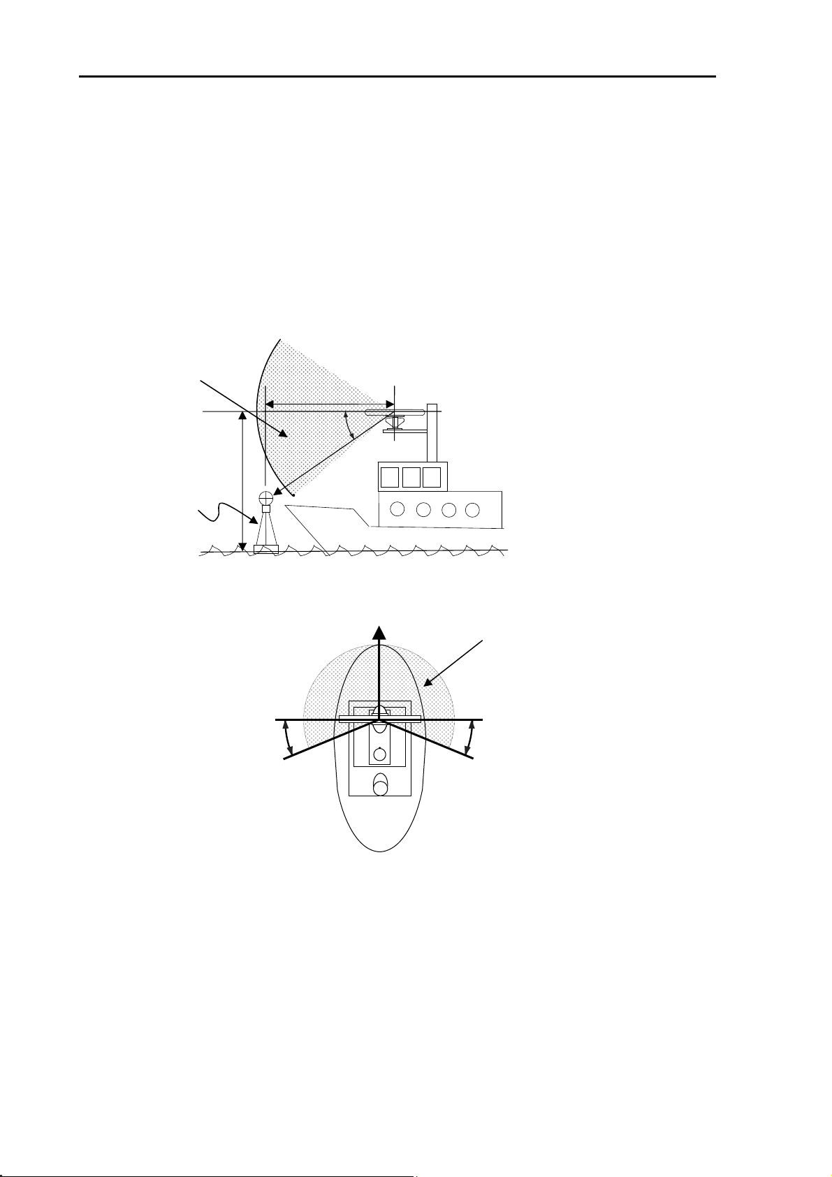
1.4.1 Antenna Scanner unit
(1) Blind sectors shall be kept to a minimum, and shall not be placed in an arc of the horizon from the
right ahead direction to 22.5° abaft the beam and especially shall avoid the right ahead direction
(relative bearing 000°). The installation of the antenna shall be in such a manner that the
performance of the radar system is not substantially degraded. The antenna shall be mounted
clear of any structure that may cause signal reflections, including other antenna and deck structure
or cargo. In addition, the height of the antenna shall take account of target detection performance
relating to range of first detection and target visibility in sea clutter.
This area is prohibited from
setting up of the structure.
Navigation buoy with
corner reflector
ntenna
height
=15m
Minimum range
40m
16°
Figure 1.1 Vertical chart of recommended antenna installation position.
BOW
Figure 1.2 Horizontal chart of recommended antenna installation position.
(2) Keep the surface of the Antenna-Scanner unit platform horizontal as much as possible.
When the antenna height
rises, Minimum Range
becomes long.
mum
range(m)
ntenna
=(
height(m)
This area is prohibited from setting
up of the structure.
22.5°22.5°
(3) The Antenna-Scanner unit should be installed in front of large objects or exhaust stack to prevent a
blind sector or the effects on the antenna by engine exhaust soot.
(4) Keep sufficient maintenance area.
(5) Keep safety distance from magnetic compass.
1-2 0092669006-05E
Page 13
MDC-7000P/7900P Series Chapter 1 Prior to installation
Table 1.1 Safety distance of compass from the Scanner unit
Scanner unit type Standard compass Steering compass
RB808P 1.4 m 0.9 m
RB809P 1.4 m 0.9 m
1.4.2 Display unit and Operation unit
(1) The orientation of the Display unit shall be such that the user is looking ahead, the lookout view is
not obscured and there is minimum ambient light on the display viewing surface.
(2) Choose the best location from humidity, spray, rain, and direct sunlight.
(3) Keep sufficient maintenance area. Especially sufficient space is required near the back panel
where cables are connected.
(4) Keep as far as possible from other radio devices.
(5) Keep safety distance from magnetic compass.
Table 1.2 Safety distance of compass from Display units
Display unit type Standard compass Steering compass
MRD-108P 2.2 m 1.2 m
MRM-108P 1.2 m 0.7 m
MRO-108P 0.3 m 0.3 m
0092669006-05E 1-3
Page 14

Chapter 1 Prior to installations MDC-7000P/7900P Series
1.5 Cable wiring and interconnection
1.5.1 Antenna Scanner unit
(1) The connecting cable between the Antenna-Scanner unit and the Display unit should run apart
from any other radio antenna cable or power cables of the other devices. Do not lay the radar cable
in parallel to the sea surface together with other cables. These considerations are effective to
prevent random radio interference between systems. When these measures cannot be applied
because of space limitations, use metal pipes for each cable or other suitable ways to shield.
(2) In order to maximize the performance of the radar, the antenna cable and the power cable should
be as short as possible, and should be laid within the nominal length.
(3) Connect the shielded braided wire of the antenna cable to the grounding terminal inside the
Antenna unit
1.5.2 Display unit
(1) Ground the braided wire of a cable firmly with the cable clamp fixing screw to the back panel.
(2) The Display unit housing should be grounded to the ship ground by using the ground terminal of
the back panel.
1-4 0092669006-05E
Page 15

MDC-7000P/7900P Series Chapter 2 System configurations
Chapter 2 System configurations
2.1 Standard configuration list
MDC-7912P
No. Name Type Comment Weight/
Length
1 Antenna RW701A-04 4 ft 6 kg 1
RW701A-06 6 ft 8 kg
RW701B-09 9 ft 12 kg
2 Scanner unit RB808P 12 kW 18.5kg 1
3 Display unit MRD-108P 13 kg 1
4 Operation unit MRO-108P With CW-401-2M 1.8 kg 1
5 Junction box JB-35 With CW-376-5M 1
6 Connecting cable CW-845-15M With connectors on the
both sides
7 Power cable CW-259-2M With a connector on the
single side
8 Spare parts SP-MRD/MRM-108 See spare parts list 1 set
9 Installation material M12-BOLT.KIT See installation material
list
10 Document MDC-7000P_7900P.OM.E Operation manual 1
15 m 1
2 m 1
1 set
Quantity
11 Document MDC-7000P_7900P.IM.E Installation manual 1
12 Document MDC-7000P_7900P.QR.E Quick reference 1
0092669006-05E 2-1
Page 16

Chapter 2 System configurations MDC-7000P/7900P Series
MDC-7925P
No. Name Type Comment Weight/
Length
1 Antenna RW701A-04 4 ft 6kg 1
RW701A-06 6 ft 8 kg
RW701B-09 9 ft 12 kg
2 Scanner unit RB809P 25 kW 20.5 kg 1
3 Display unit MRD-108P 13 kg 1
4 Operation unit MRO-108P With CW-401-2M 1.8 kg 1
5 Junction box JB-35 With CW-376-5M 1
6 Connecting cable CW-845-15M With connectors on the
both sides
7 Power cable CW-259-2M With a connector on the
single side
8 Spare parts SP-MRD/MRM-108 See spare parts list 1 set
9 Installation material M12-BOLT.KIT See installation material
list
10 Document MDC-7000P_7900P.OM.E Operation manual 1
15 m 1
2 m 1
1 set
Quantity
11 Document MDC-7000P_7900P.IM.E Installation manual 1
12 Document MDC-7000P_7900P.QR.E Quick reference 1
2-2 0092669006-05E
Page 17

MDC-7000P/7900P Series Chapter 2 System configurations
MDC-7012P
No. Name Type Comment Weight/
Length
1 Antenna RW701A-04 4 ft 6 kg 1
RW701A-06 6 ft 8 kg
RW701B-09 9 ft 12 kg
2 Scanner unit RB808P 12 kW 18.5 kg 1
3 Processor unit MRM-108P 5.1 kg 1
4 Operation unit MRO-108P With CW-401-2M 1.8 kg 1
5 Junction box JB-35 With CW-376-5M 1
6 Connecting cable CW-845-15M
7 Power cable CW-259-2M
8 Display cable CW-592-3M
9 Spare parts SP-MRD/MRM-108 See spare parts list 1 set
10 Installation material M12-BOLT.KIT See installation material list 1 set
11 Document
12 Document
MDC-7000P_7900P.OM.
E
MDC-7000P_7900P.IM.E
With connectors on the both
sides
With a connector on the
single side
With D-sub connector for
Analog RGB monitor and
DVI connector for radar
Operation manual 1
Installation manual 1
15 m 1
2 m 1
3m 1
Quantity
13 Document MDC-7000P_7900P.QR.E Quick reference 1
0092669006-05E 2-3
Page 18

Chapter 2 System configurations MDC-7000P/7900P Series
MDC-7025P
No. Name Type Comment Weight/
Length
1 Antenna RW701A-04 4 ft 6 kg 1
RW701A-06 6 ft 8 kg
RW701B-09 9 ft 12 kg
2 Scanner unit RB809P 25 kW 20.5 kg 1
3 Processor unit MRM-108P 5.1 kg 1
4 Operation unit MRO-108P With CW-401-2M 1.8 kg 1
5 Junction box JB-35 With CW-376-5M 1
6 Connecting cable CW-845-15M
7 Power cable CW-259-2M
8 Display cable CW-592-3M
9 Spare parts SP-MRD/MRM-108 See spare parts list 1 set
10 Installation material M12-BOLT.KIT See installation material list 1 set
11 Document
12 Document
MDC-7000P_7900P.OM.
E
MDC-7000P_7900P.IM.E
With connectors on the both
sides
With a connector on the
single side
With D-sub connector for
Analog RGB monitor and
DVI connector for radar
Operation manual 1
Installation manual 1
15 m 1
2 m 1
3m 1
Quantity
13 Document MDC-7000P_7900P.QR.E Quick reference 1
2-4 0092669006-05E
Page 19
MDC-7000P/7900P Series Chapter 2 System configurations
2.2 Spare parts list
SP-MRD/MRM-108
No. Name Specification Comment Type
(Dimension)
1 Fuse F-1065-15A Normal type Tubular
(φ6.4 x 30)
2 Fuse FGMB 125V/10A Normal type Tubular
(φ5.2 x 20)
3 Fuse FGMB 250V/0.8A Normal type Tubular
(φ5.2 x 20)
Quantity Usage
1 Main power
1 Motor power
1 High voltage power
supply
2.3 Installation material list
M12-BOLT.KIT
No. Name Specification Quantity Usage
1 Hexagon bolt B12X55U 4 Antenna-Scanner unit
2 Nut N12U 8 Antenna-Scanner unit
3 Plain washer 2W12U 8 Antenna-Scanner unit
4 Spring washer SW12U 4 Antenna-Scanner unit
5 Anti electro corrosive
washer
6 Anti electro corrosive
washer
7 Ferrite core GRFC-13 1 Antenna-Scanner unit
8 Cable band AB150-W 2 Antenna-Scanner unit
56R7201M2 4 Antenna-Scanner unit
56R7202M2 4 Antenna-Scanner unit
0092669006-05E 2-5
Page 20

Chapter 2 System configurations MDC-7000P/7900P Series
2.4 Options
(Common)
No. Name Specification Comment Weight
/Dimension
/Quantity
1 Gyro converter S2N, U/N 9028C qwerty-electronik
2 Log pulse NMEA
converter
3 Rectifier unit PS-010 5A fuse attached
4 AC power cable VV-2D8-3M Without connectors on both
5 Connecting cable
6
Operation unit
L1N, U/N 9181A
VL-PSG001 VEINLAND GmbH
CW-373-
select 5M,10M or 30M
CW-374-5M With a 6-pin connector and a
CW-376-5M With a 6-pin water resistant
CW-387-5M With a 8-pin water resistant
CW-561-
select 10M or 30M
CW-576-0.5M With a 10-pin water resistant
CW-560-2M With 15-pin water resistant
CW-401-
qwerty-electronik
200pulse/NM only
For 4 or 6 feet antenna only.
for RW701B-09
sides
With 6-pin water resistant
connectors at both ends
(cable for data)
6-pin water resistant
connector (cable for data)
connector and one end plain
(cable for data)
connector and one end plain
(cable for AIS)
With 12-pin water resistant
connectors at both ends
(connector for remote
display)
connector and D-Sub
connector (analog RGB)
+Alarm out
D-Sub connectors at both
ends
(Cable for VDR or external
Display unit to connect
CW-576-0.5M)
With connectors on both
3.5 kg
3 m
5 m, 10 m
or 30 m
5 m
5 m
5 m
10 m or 30 m
0.5 m
2 m
5 m or 10 m
connecting cable
7 Antenna-Scanner unit
and Display unit
connecting cable
2-6 0092669006-05E
select 5M or 10M
CW-845-
select 20M, 30M, 50M
or 65M
sides
With connectors on both
sides
20 m, 30 m,
50 m or 65 m
Page 21
MDC-7000P/7900P Series Chapter 2 System configurations
A
A
r
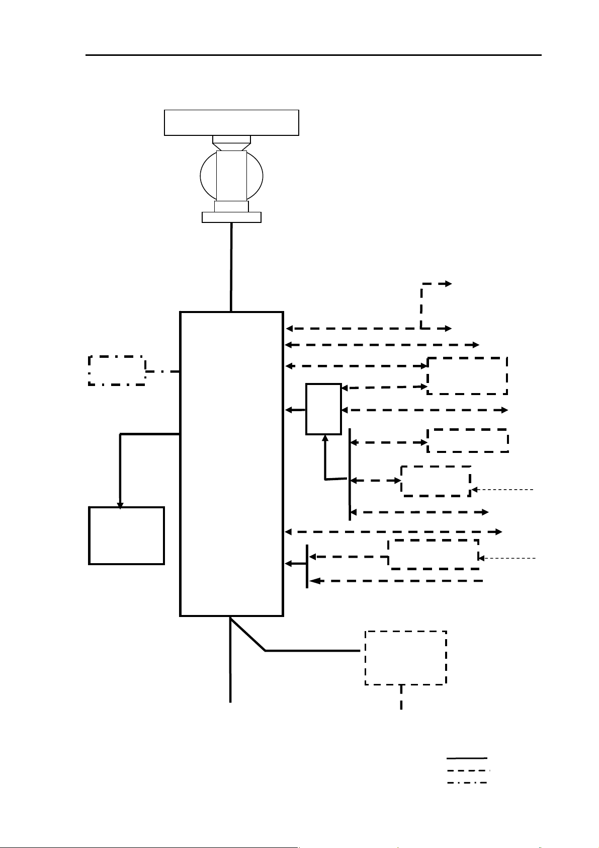
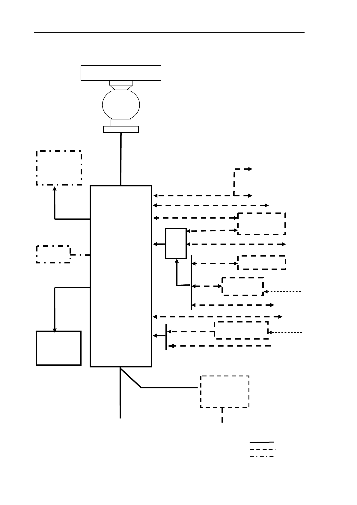
2.5 MDC-7912P/7925P series system configuration
Scanner unit
USB Mouse/
Trackball.
Connecting cable
CW-401-2M
RB808P
RB809P
USB
J9
J7
Display unit
MRD-108P
Antenna
RW701A-04
RW701A-06
RW701B-09
Connecting cable
CW-845-15M (Standard)
CW-845-20M
CW-845-30M
CW-845-50M
CW-845-65M
J1
J2
J8
J3
NAV
CW-576-0.5M
CW-387-5M
CW-561-10M
JB
-35
The device connected with radar
must be compliant with following
resolutions.
SDME: Resolution MSC.96 (72)
GPS: Resolution MSC.112 (73)
DGPS: Resolution MSC.114 (73)
THD: Resolution MSC.116 (73)
AIS: Resolution A.917 (22)
VDR: Resolution A.861 (20)
Alarm out
VDR or External monito
CW-560-2M
IS
Slave display
MRD-108P
+MRO-108P
GPS Compass
OTHER
Operation unit
MRO-108P
POWER
Power cable
CW-259-2M
Onboard DC power supply
21.6 to 41.6VDC
J6
J5
CW-376-5M
CW-376-5M
CW-376-5M
VL-PSG001
Onboard AC power supply
100/115VAC
200/230VAC
S2N
Gyro converter
L1N Log pulse NMEA
converter
Rectifier
PS-010
or
C power cable
VV-2D8-3M
Gyro synchro or
Step signal
Gyro NMEA
signal
EPFS
LOG pulse
SDME
Standard
Option
Owner supplied
0092669006-05E 2-7
Page 22
Chapter 2 System configurations MDC-7000P/7900P Series
A
A
2.6 MDC-7012P/7025P series system configuration
Scanner unit
RB808P
RB809P
External monitor
Display cable
CW-592-3M
USB Mouse/
Trackball.
DVI-A
USB
J7
Processor unit
MRM-108P
Antenna
RW701A-04
RW701A-06
RW701B-09
Connecting cable
CW-845-15M (Standard)
CW-845-20M
CW-845-30M
CW-845-50M
CW-845-65M
J1
J2
J8
J3
NAV
CW-576-0.5M
CW-387-5M
CW-561-10M
JB
-35
The device connected with radar
must be compliant with following
resolutions.
SDME: Resolution MSC.96 (72)
GPS: Resolution MSC.112 (73)
DGPS: Resolution MSC.114 (73)
THD: Resolution MSC.116 (73)
AIS: Resolution A.917 (22)
VDR: Resolution A.861 (20)
Alarm out
VDR
CW-560-2M
IS
Slave display
MRD-108P
+MRO-108P
GPS Compass
OTHER
Connecting cable
CW-401-2M
Operation unit
MRO-108P
J9
POWER
Power cable
CW-259-2M
Onboard DC power supply
21.6 to 41.6VDC
J6
J5
CW-376-5M
CW-376-5M
CW-376-5M
VL-PSG001
Onboard AC power supply
100/115VAC
200/230VAC
S2N
Gyro converter
L1N Log pulse NMEA
converter
Rectifier
PS-010
or
C power cable
VV-2D8-3M
Gyro synchro or
Step signal
Gyro NMEA
signal
EPFS
LOG pulse
SDME
Standard
Option
Owner supplied
2-8 0092669006-05E
Page 23
MDC-7000P/7900P Series Chapter 3 Installation Method
Chapter 3 Installation Method
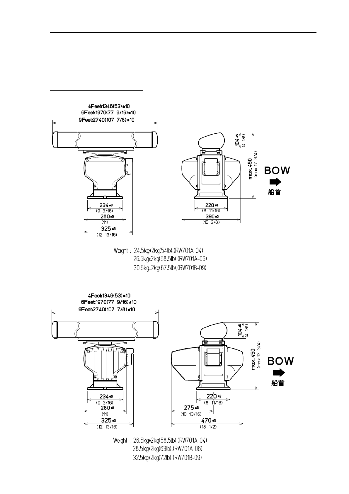
3.1 How to install the Antenna Scanner unit
External view and dimensions
RB808P
RB809P
Unit: mm (inch)
0092669006-05E 3-1
Page 24
Chapter 3 Installation Method MDC-7000P/7900P Series
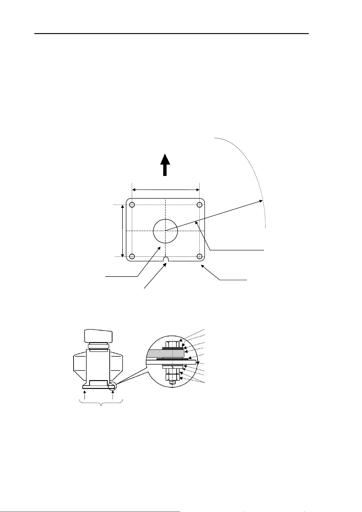
3.1.1 Installation of the Antenna Scanner unit
The Antenna Scanner unit is equipped to orient the notch of the attachment to stern as shown in Figure
3.1. Installation in this way eases maintenance work. Also refer to the consideration on equipment
shown in 1.4.1.
(1) Four mounting holes 14 mm in diameter are located on the mounting platform with reference to
Figure 3.1.
(2) The Antenna Scanner unit is secured with four 12 mm stainless steel bolts contained in installation
material.
Heading
199
(7.83)
185
(7.28)
Antenna rotating radius
R700 (4 ft Antenna unit)
R1000 (6 ft Antenna unit)
R1400 (9 ft Antenna unit)
Cable opening
(3.97)
φ
100
Notch of Scanner
Figure 3.1 Plain view of mounting hole
RA774UA
14φx 4
(0.55)
Unit: mm (inch)
M12 bolt
Washer
Anti-electro corrosive washer
Scanner unit base
Anti-electro corrosive washer
Platform
Washer
Spring washer
M12 Double nut
Mounted with four bolts
Figure 3.2 Assembly of Scanner unit base
3-2 0092669006-05E
Page 25
MDC-7000P/7900P Series Chapter 3 Installation Method
A
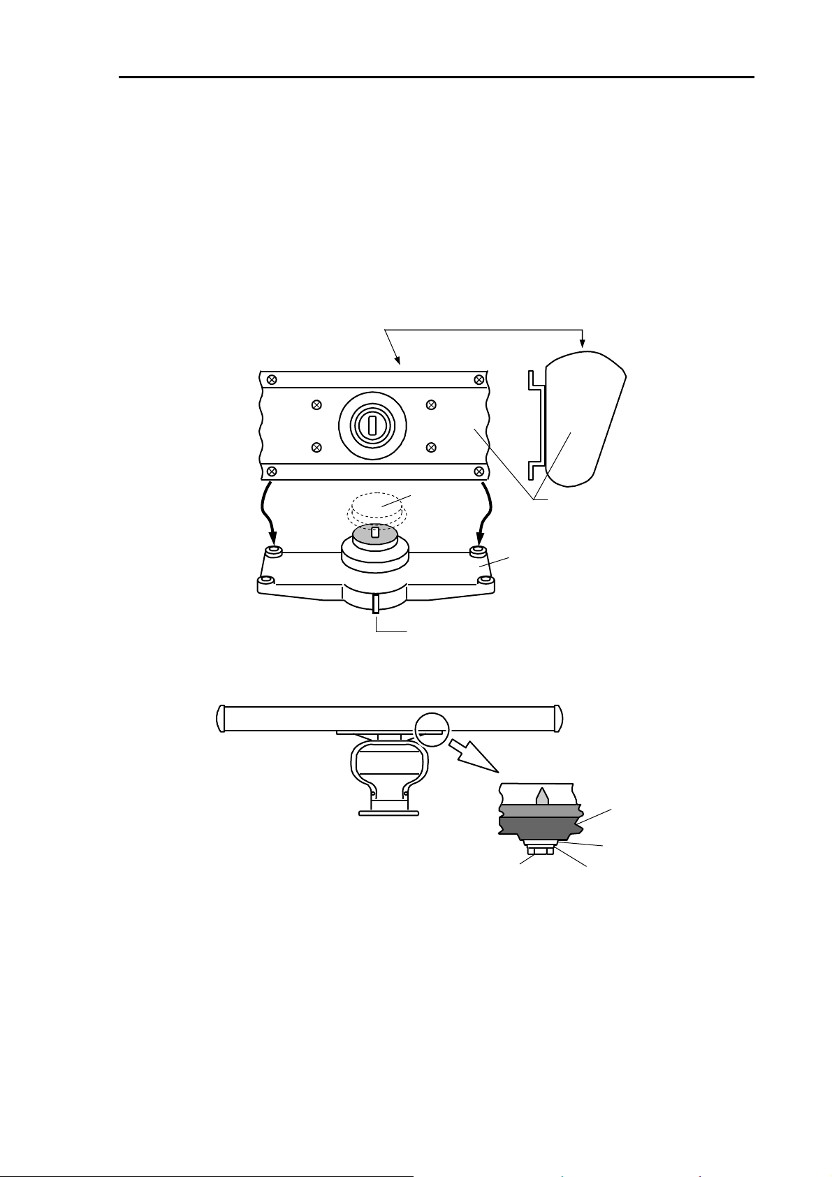
3.1.2 Mounting antenna
(1) Remove the protective cap on top of the Scanner unit rotational shaft.
(2) Remove four bolts tentatively fixed to the base of the antenna and install the Scanner unit to the
rotating base. Align the direction of antenna radiation side (KODEN –mark side) with the projection
mark on the rotating base.
(3) Fix the aerial with four bolts removed in step 2.
Antenna radiation side (KODEN –mark side)
Remove
Protective cap
Projection mark
Installation bolt
ntenna
Rotating base
Rotating base
Flat washer
Spring washer
Figure 3.3 Antenna assembly to the rotating shaft
0092669006-05E 3-3
Page 26
Chapter 3 Installation Method MDC-7000P/7900P Series
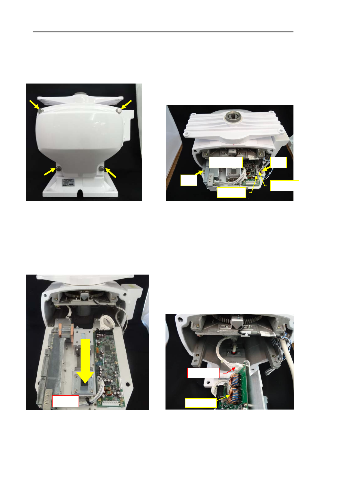
3.1.3 Installation of the connecting cable CW-845-xxM
3.1.3.1 MDC-7012P/7912P (Scanner unit RB808P)
Make sure the radar system is turned off.
1) Remove back cover by loosening four fixing
bolts.
(Tool: Wrench 13mm)
PCB: E61-120X
Bolt
P3 <- J3
Bolt
P4 <- J4
2) Disconnect connectors P3 and P4 from J3
and J4 [E61-120X].
Remove the two fixing bolts.
(Tool: Wrench 13mm)
P2 <- J2
TR unit
3) Pull out the TR unit.
4) Disconnect connector P2 from J2
PCB: E61-110X
[E61-110X].
3-4 0092669006-05E
Page 27
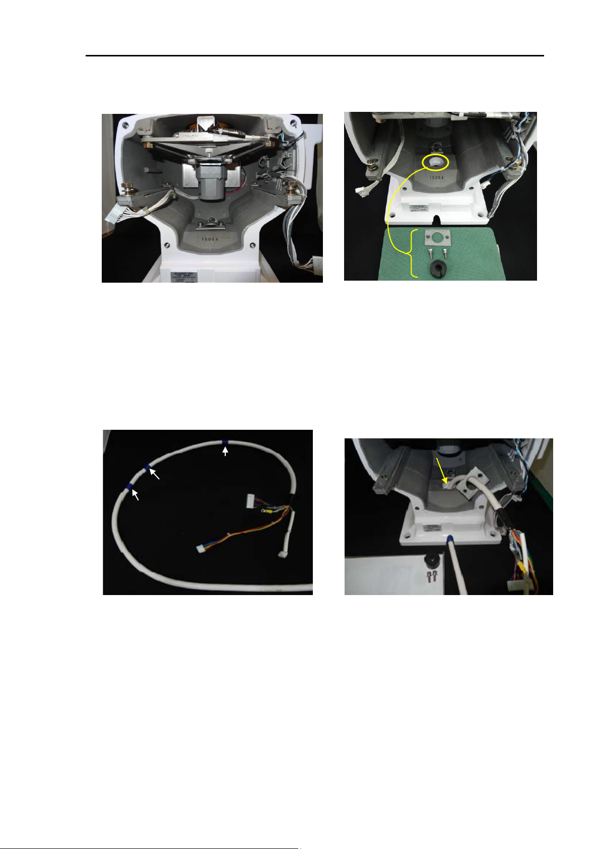
MDC-7000P/7900P Series Chapter 3 Installation Method
(b)
(c)
(d)
(a)
5) This picture is the view of the inside of the
scanner unit housing.
(a) Cable holding plate
(b) Cable clamp-b
(c) Cable clamp-c
(d) Cable clamp-d
Blue tape mark-c
Blue tape mark-b
Blue tape mark-a
Cable holding plate
Fixing bolt (8mm)
Rubber packing
6) Remove two fixing bolts.
(Tool: Wrench 8mm)
Remove the cable holding plate and
rubber packing.
Cable inlet hole
Connecting cable
7) The connecting cable CW-845-xxM
Blue tapes are wound as a mark on the cable.
8) Pull in the connecting cable into the
scanner unit through the cable inlet hole.
Guide the cable to the cable holding plate.
0092669006-05E 3-5
Page 28
Chapter 3 Installation Method MDC-7000P/7900P Series
Blue tape mark-a
Rubber packing
9) Attach rubber packing to the blue tape
Mark-a.
Ferrite core
Blue tape mark-b
Cable holdingr plate
10) Attach cable holding plate and fix it
with two bolts.
(Tool: Wrench 8mm)
Ferrite core
Band
11) Attach the ferrite core to side of the
blue tape mark–b.
Band
12) Secure the ferrite core in place by using
provided bands.
Note: The ferrite core and the bands are included
with the installation material.
3-6 0092669006-05E
Page 29
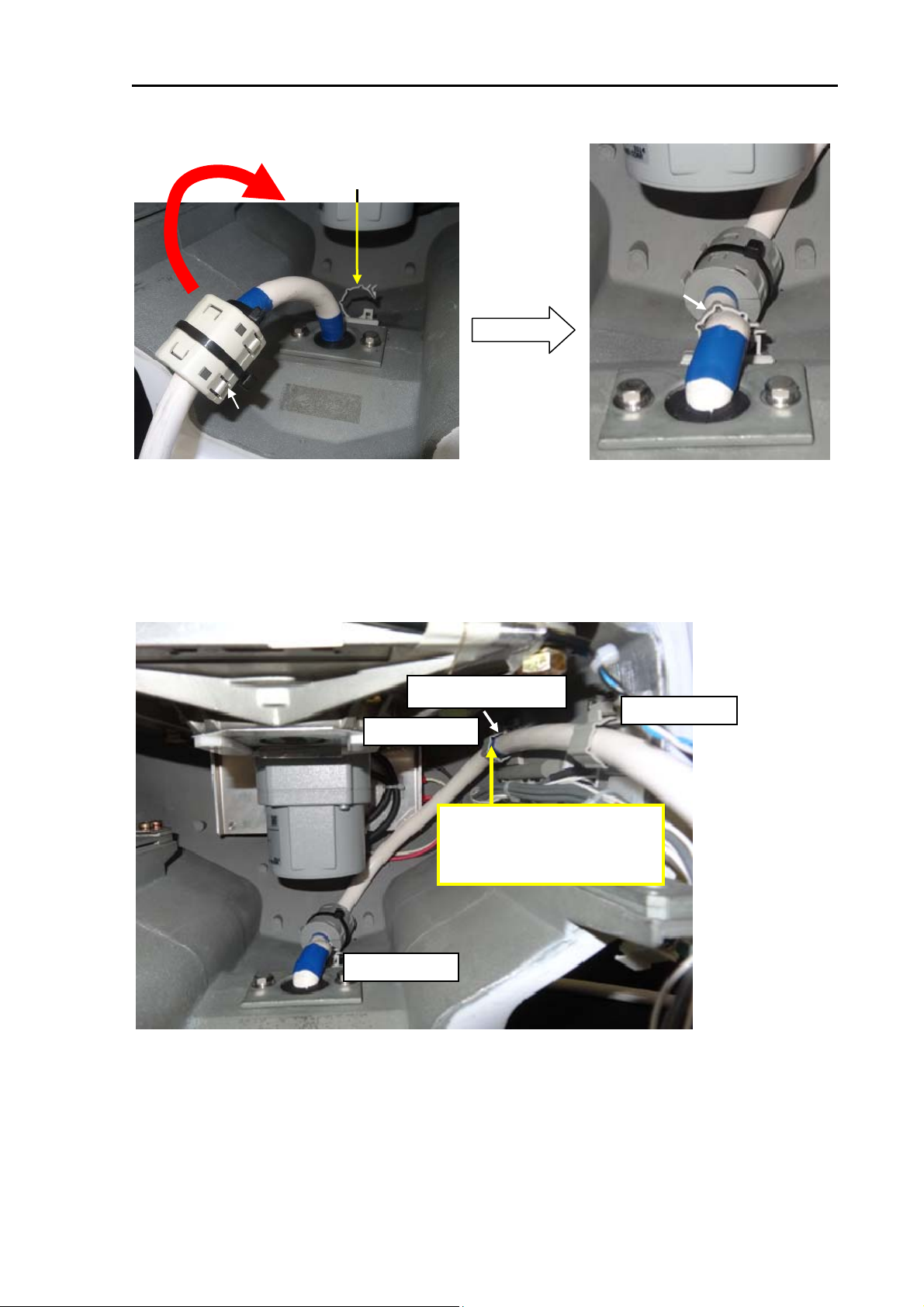
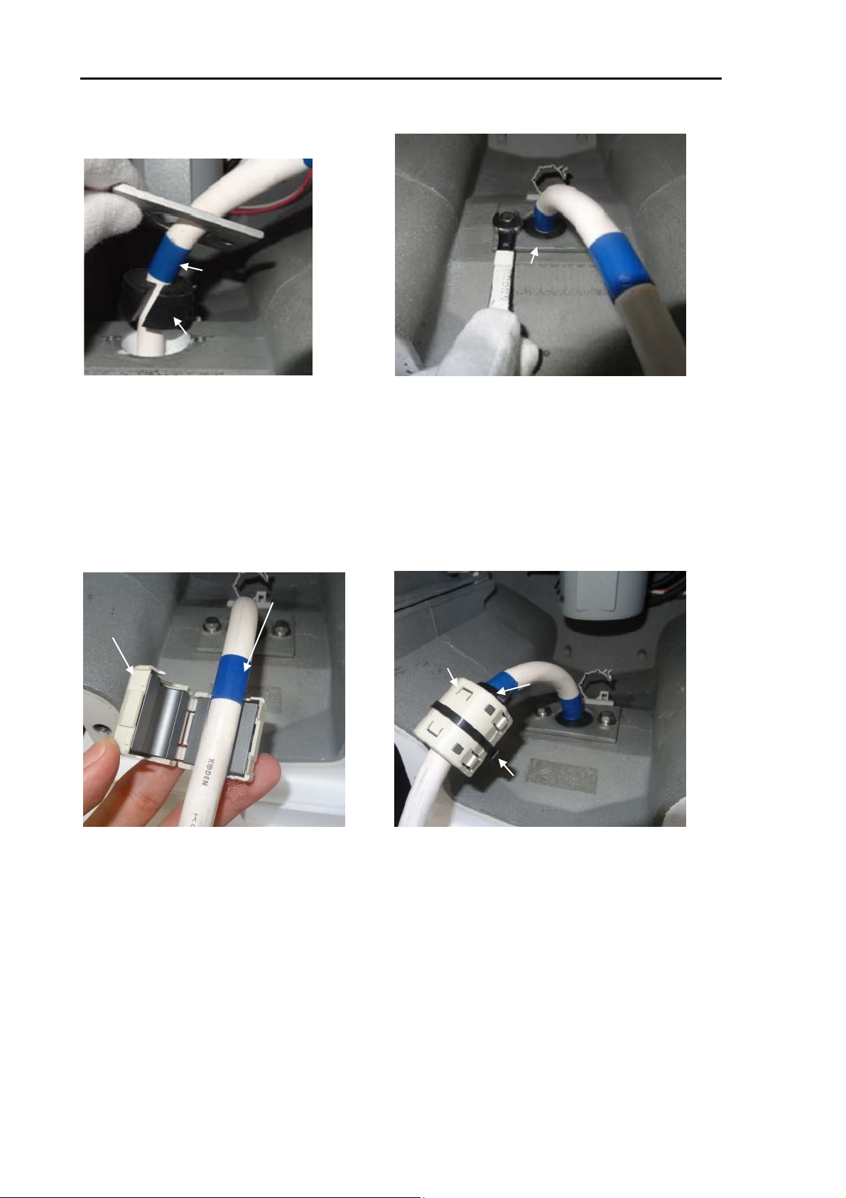
MDC-7000P/7900P Series Chapter 3 Installation Method
Cable clamp-b
Ferrite core
13) Tilt the cable with the ferrite core
toward the cable clamp-b.
Ferrite core
Cable clamp-b
14) Clamp the cable by the cable
clamp-b.
Blue tape mark-c
Cable clamp-c
Clamp the blue tape mark by
the cable clamp-c.
Cable clamp-b
15) This picture is the view of the cable layout.
Clamp the blue tape mark-c by the cable clamp-c.
Cable clamp-d
0092669006-05E 3-7
Page 30
Chapter 3 Installation Method MDC-7000P/7900P Series
P2 -> J2
PCB: E62-110X
16) Connect connector P2 to J2
[PCB 62-110X].
P2 -> J2
Clamp
17) Hook the P2 to J2 to the clamp.
TR unit
18) Insert the TR unit in the scanner
unit housing.
PCB: E61-120X
Bolt
P4 -> J4
P3 -> J3
19) Connect connectors P3 and P4 to J3 and J4 [PCB
E61-120X]
Fix the two fixing bolts.
(Tool: Wrench 13mm)
Bolt
3-8 0092669006-05E
Page 31

MDC-7000P/7900P Series Chapter 3 Installation Method
B
A
Clamping band
20) Remove the screw-A and the screw-B.
Connecting cable
Shield braid terminal
Clamping band
21) Clamp the connecting cable by the
clamping band and fix with screw-A.
Fix the shield braid terminal with screw-B.
P2 -> J2
PCB: E61-120X
P3 -> J3
PCB: E61-120X
P1 -> J1
22) Connect connector P2 to J2 [PCB E61-120x].
Connect the connectors P1 and P3 to J1 and J3
[PCB E61-110X].
23) Attach the back cover by tightening four fixing
bolts.
(Tool: Wrench 13mm)
0092669006-05E 3-9
Page 32

Chapter 3 Installation Method MDC-7000P/7900P Series
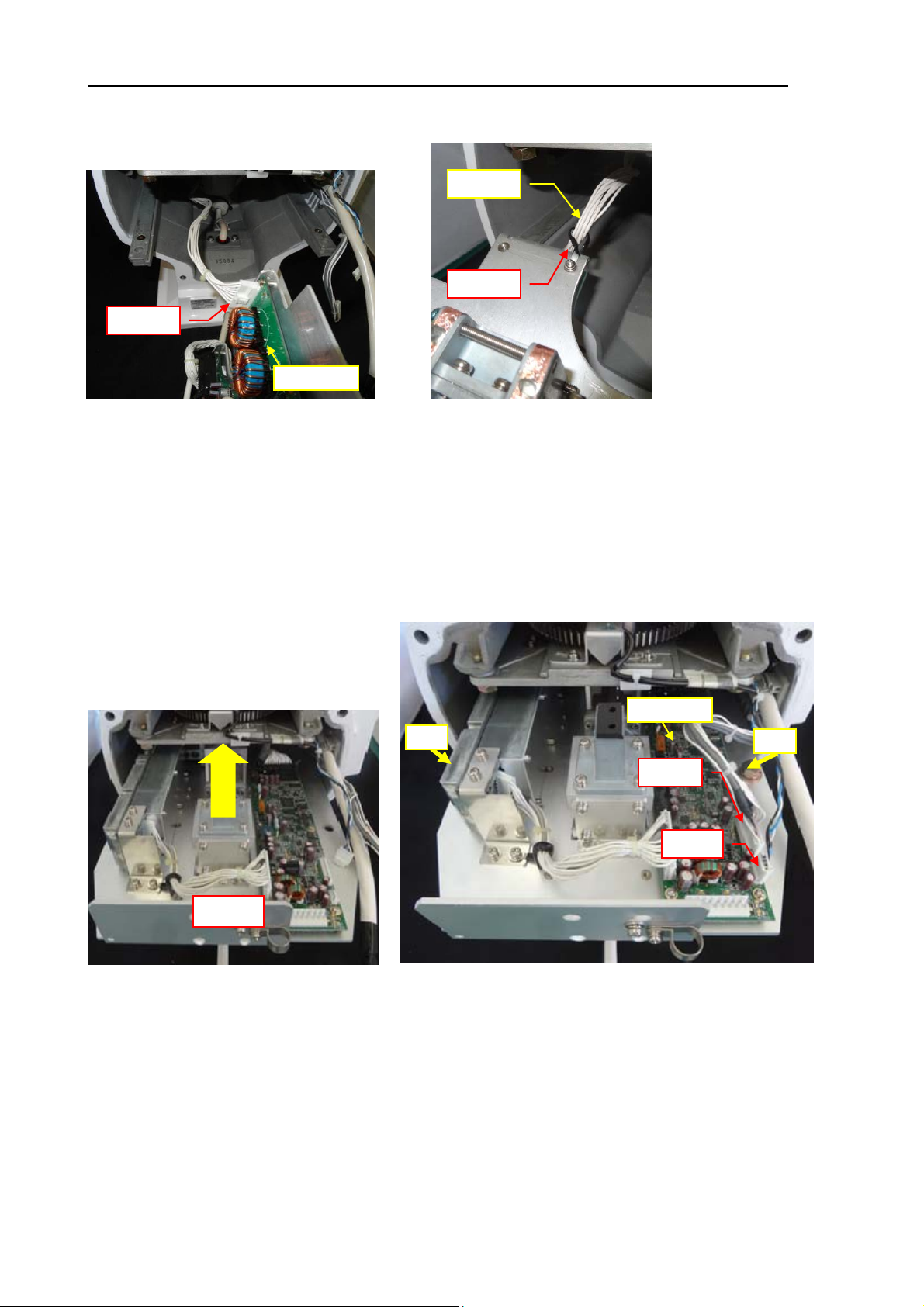
3.1.3.2 MDC-7025P/7925P (Scanner unit RB809P)
Make sure the radar system is turned off.
1) Remove the back cover by loosening four fixing
bolts.
(Tool: Wrench 13mm)
Bolt
PCB: E61-120X
P4 <- J4
P3 <- J3
2) Disconnect connectors P3 and P4 from J3
and J4 [E61-120X].
Remove the two fixing bolts.
(Tool: Wrench 13mm)
Bolt
P2 <- J2
TR unit
3) Pull out the TR unit. 4) Disconnect connector P2 from J2
3) Pull out the TR unit. 4) Disconnect connector P2 from J2
PCB: E62-110X
[E62-110X].
[E62-110X].
3-10 0092669006-05E
Page 33

MDC-7000P/7900P Series Chapter 3 Installation Method
(c)
(b)
(a)
5) This picture is the view of the inside of the
scanner unit housing.
(a) Cable holding plate
(b) Cable clamp-b
(c) Cable clamp-c
(d) Cable clamp-d
Blue tape mark-c
(d)
Cable holding plate
Fixing bolt (8mm)
Rubber packing
6) Remove the fixing two bolts.
(Tool: Wrench 8mm)
Remove cable holding plate and
rubber packing.
Cable inlet hole
Blue tape mark-b
Blue tape mark-a
Connecting cable
7) The connecting cable CW-845-xxM
Blue tapes are wound as a mark on the cable.
8) Pull in the connecting cable into the scanner unit
through the cable inlet hole.
Guide the cable to the cable holding plate.
0092669006-05E 3-11
Page 34

Chapter 3 Installation Method MDC-7000P/7900P Series
Blue tape mark-a
Cable holdingr plate
Rubber packing
9) Attach rubber packing to the blue tape
Mark-a.
Blue tape mark-b
Ferrite core
10) Attach cable holding plate and fix it with
two bolts.
(Tool: Wrench 8mm)
Ferrite core
Band
Band
11) Attach the ferrite core to side of the
blue tape mark–b.
12) Secure the ferrite core in place by using
provided bands.
Note: The ferrite core and the bands are included
with the installation material.
3-12 0092669006-05E
Page 35

MDC-7000P/7900P Series Chapter 3 Installation Method
Cable clamp-b
Ferrite core
13) Tilt the cable with the ferrite core
toward the cable clamp-b.
Ferrite core
Cable clamp-b
14) Clamp the cable by the cable
clamp-b.
Blue tape mark-c
Cable clamp-c
Clamp the blue tape mark by
the cable clamp-c.
Cable clamp-b
15) This picture is the view of the cable layout.
Clamp the blue tape mark-c by the cable clamp-c.
Cable clamp-d
0092669006-05E 3-13
Page 36

Chapter 3 Installation Method MDC-7000P/7900P Series
P2 -> J2
PCB: E62-110X
16) Connect connector P2 to J2
[PCB 62-110X].
P2 -> J2
Clamp
17) Hook the P2 to J2 to the clamp.
TR unit
18) Insert the TR unit in the scanner
unit housing.
PCB: E61-120X
Bolt
P4 -> J4
P3 -> J3
19) Connect connectors P3 and P4 to J3 and J4 [PCB
E61-120X]
Fix the two fixing bolts.
(Tool: Wrench 13mm)
Bolt
3-14 0092669006-05E
Page 37

MDC-7000P/7900P Series Chapter 3 Installation Method
Connecting cable
Shield braid terminal
Clamping band
B
A
20) Remove screw-A and screw-B.
21) Clamp the connecting cable by the
Clamping band
clamping band and fix with screw-A.
Fix the shield braid terminal with screw-B.
P2 -> J2
PCB: E61-120X
P3 -> J3
PCB: E62-110X
P1 -> J1
22) Connect connector P2 to J2 [PCB
E61-120x].
Connect connectors P1 and P3 to J1 and J3
[PCB E62-110X].
23) Attach the back cover by tightening four
fixing bolts.
(Tool: Wrench 13mm)
0092669006-05E 3-15
Page 38

Chapter 3 Installation Method MDC-7000P/7900P Series
3.2 Interconnection diagram of cable
Antenna-Scanner unit Display unit
Description Cable color No. No. Cable color Description
+24V Blue 1 1 Purple +250V
- - 2 2 Blue +24V
+12V Oran g e (thick)
DA TA-RTN Shi eld 4 4 Ye llow GND
DATA Red (coax) 5 5 Shield DATA-RTN
BP/SHF-RTN Shield 6 6 Red (coax) DATA
BP/SHF Brown (coax) 7 7 - V/TRG-RTN Shied 8 8 Brown (coax) BP/SHF
V/TRG Grey (coax) 9 9 Shield BP/SHF-RTN
Description Cable color No. 12
+250V Purple 1 13
-- 2 14ShiedV/TRG-RTN
GND Yellow 3 15
Description Cable color No.
+53V Red (thick)
+53V Yell o w (thi ck)
+53V -RTN Gre en (thick)
+53V -RTN Blue (thi ck)
P1 PX
33
P2
Ora n g e (thick) + 12V
10 Grey (coax) V/TRG
11 - -
Red (thick) +53V
Yel low (thick) +53V
Gre en (thick) +53V-RTN
16
Blue (thi ck) +53V-RTN
P3
1
2
3
4
Ground
GND Shield
Figure 3.4 Interconnection of cable between Antenna-Scanner unit and Display unit
3-16 0092669006-05E
Page 39

MDC-7000P/7900P Series Chapter 3 Installation Method
3.3 Installation of the Display unit
The Display unit can be mounted tabletop or panel flush mount using following procedures.
Install the Display unit so that when user is looking ahead, the lookout view is not obscured. The
orientation of the Display unit should be such that the user is looking ahead. The lookout view should
not be obscured and the ambient light should cause minimum degradation on the display.
External view and dimensions
MRD-108P
MRO-108P
0092669006-05E 3-17
Unit: mm (inch)
Page 40

Chapter 3 Installation Method MDC-7000P/7900P Series
MRM-108P
Unit: mm (inch)
3-18 0092669006-05E
Page 41

MDC-7000P/7900P Series Chapter 3 Installation Method
3.3.1 Installation of MRD-108P
3.3.1.1 Tabletop mounting of MRD-108P
(1) Remove four knob bolts from which the Display unit is secured on the mounting bracket.
(2) Remove the Display unit from the mounting bracket and put it on a stable, flat and horizontal place.
(3) Place the mounting bracket in the appropriate setting position and secure it with five M5 screws.
(4) Remount the Display unit on the mounting bracket and secure it with knob bolts which were
removed in (1)
Display unit
M5 screw
(5 places)
Knob bolt
(4 places)
Mounting bracket
Unit: mm (inch)
Figure 3.5 Diagram of installation procedure on the table
0092669006-05E 3-19
Page 42

Chapter 3 Installation Method MDC-7000P/7900P Series
Note: In Tabletop mounting position, some maintenance space is required for cabling, connector
access, fuse replacement, fastening of bolts, etc. as shown in the following figure.
Figure 3.6 Maintenance space necessary for tabletop display
Unit: mm (inch)
3-20 0092669006-05E
Page 43

MDC-7000P/7900P Series Chapter 3 Installation Method
3.3.1.2 Flush Mounting for MRD-108P
Preparation:
(1) Cut an opening and drill eight
4.5 mm holes as shown in
Figure 3.7, for attachment of a
Display unit in a panel.
(2) Unscrew four knob bolts that
hold the Display unit to the
mounting bracket.
(3) Remove the Display unit from
the mounting bracket and put it
on a horizontal and stable
place.
8-φ4.5(11/64)
Installation:
(1) Place the Display unit in the precut opening on the panel.
(2) Secure the Display unit with eight M4 screw as shown in the following figure.
Figure 3.7 The opening and nut-holes for Display unit
M4 screw
(8 places)
Unit: mm (inch)
0092669006-05E 3-21
Display unit
Figure 3.8 Flush-mount Installation
Page 44

Chapter 3 Installation Method MDC-7000P/7900P Series
3.3.2 Installation of Operation unit
(1) Remove the corner guard caps of Operation unit. Insert the tip of a small flat-blade screwdriver
carefully between a corner guard cap and the front bezel of Operation unit to make a gap, and then
pinch and pull up the corner guard cap with fingers. Take care not to damage the bezel of
Operation unit by the tip of flat-blade screwdriver.
(2) Remove M4 (4 mm) screws and remove the Operation unit from the mounting bracket.
(3) Mark the place as shown in the following figure, and then secure the mounting bracket with 5M (5
mm) tapping screws at four places.
(4) Secure the Operation unit to clamps with M4 (4 mm) screws that were removed in step (2) and
reinstall the corner caps.
Clamp (right)
Operation unit
Corner guard cap (4 places)
M4 screw
(4 places)
M5 screw
(4 places)
Clamp (left)
3-22 0092669006-05E
Figure 3.9 Installation of Operation unit
Unit : mm(inch)
Page 45

MDC-7000P/7900P Series Chapter 3 Installation Method
Mounting dimesions
100
(3 15/16)
141.5
(5 37/64)
40
(1 37/64)
Figure 3.10 Maintenance space necessary for Operation unit
Maintenance space
385
(15 5/32)
40
(1 37/64)
Unit : mm(inch)
0092669006-05E 3-23
Page 46

Chapter 3 Installation Method MDC-7000P/7900P Series
(
/
)
3.3.2.1 Flush mounting the Operation unit
Preparation:
(1)
Cut an opening as shown in Figure 3.11 in desired location on a panel.
(2) Mark position of mounting holes.
12
(15/32)
(4mm screw for 4holes)
348
(13 45/64)
64
122
12
(15/32)
Installation:
(1) Remove corner guard caps of Operation unit.
(2) Insert the Operation unit and its connecting cable into the opening and adjust the Operation
unit parallel to the mounting face (Figure 3.12).
(3) Secure the Operation unit to the panel with 4 mm tapping screw (4 places).
(4) Reinstall corner guard caps removed in (1) to the original places.
98
4 51
(4 5/64)
(3 55/64)
(12 33/64)
318
342
(13 15/32)
Figure 3.11 Cutout Daigram for Operation unit
128
(5 3/64)
12
(15/32)
Unit : mm(inch)
Corner guard cap
(4 places)
Note: Panel thickness: 10 mm (max)
M4 screw
(4 places)
Operation unit
Figure 3.12 Flush Mounting of the Operation unit
3-24 0092669006-05E
Page 47

MDC-7000P/7900P Series Chapter 3 Installation Method
3.3.3 Installation of MRM-108P
The Processor unit MRM-108P can be mounted on a table or a panel. The procedure is as follows.
(1) Drill four nut-holes with the size shown in Figure 3.13.
(2) Fit the Processor unit.
308 mm
12 1/8 inch
308 mm
12 1/8 inch
4mm screw for 4holes
308 mm
12 1/8 inch
308 mm
12 1/8 inch
Figure 3.13 Holes for mounting a Processor unit
Note: Please set the menu of monitor size to use. Refer to “4.2.11 MONITOR SIZE”.
0092669006-05E 3-25
Page 48

Chapter 3 Installation Method MDC-7000P/7900P Series
A
3.4 Cable connection to a Display unit
3.4.1 Cable connection for MRD-108P
Attach cables from an Antenna-Scanner unit, power source and Operation unit, to corresponding
receptacles as shown in Figure 3.14.
Antenna-Scanner unit
Connecting cable
CW-845-15M
Standard length: 15 m
Display unit
Operation unit
Power cable
CW-259-2M
Standard length: 2 m
DC Power supply
21.6 to 41.6 VDC
Power cable pin assignment
3
No. Wire color Signal name
1 Black DC Main power (-)
1 2
2 White DC Main power (+)
3 Grey Ground
View of CW-259 connector
C/DC Rectifier
PS-010
or
VL-PSG001
AC Power cable,
(Ordered goods)
Figure 3.14 Cable connections for standard configuration of MRD-108P Display unit
3-26 0092669006-05E
Page 49

MDC-7000P/7900P Series Chapter 3 Installation Method
p
3.4.2 Connecting an external monitor
SXGA Monitor
Analog RGB input
Display cable
CW-592-3M
Standard for MRM-108P
Analog RGB – DVI cable
Figure 3.15 Cable connection of Display unit to ext. monitor
3.4.3 Connecting a VDR or External monitor & Failure alarm output
VDR
or
External monitor
CW-560-2M
or equivalent
Failure alarm contact
output from the radar.
Contact open in case of
failure.
Switching voltage 30V
Max current ca
acity 1A
The VDR connected with radar must be compliant with
the resolution A.861 (20).
CW-576-0.5M
J1
White
Black
0092669006-05E 3-27
Figure 3.16 Cable connection of Display unit to VDR and Alarm output
Page 50

Chapter 3 Installation Method MDC-7000P/7900P Series
3.4.4 Connecting a Gyro converter unit or THD
The THD connected with radar must be compliant with resolution MSC.116 (73).
MASTER
Junction box
JB-35
SLAVE3
Wiring of MASTER port of JB-35
Pin
CW-376
No.
Wire color
1 Blue+shield GND
2 White IN-A
3 Red IN-B
4 Orange OUT-A
5 Black OUT-B
6 Green +12V
Signal
name
CW-376-5M
JB-35
(Other)
J3
SLAVE1
SLAVE2
Serial signal
IEC 61162-2
Please set the output of S2N and THD (gyro
serial output) as follows.
Baud rate=38400bps, TX cycle=25ms-50ms,
Sentence=HDT, Checksum=ON
Please refer to the Operation manual of each
unit for details.
Inter-switch data (NAV)
S2N Gyro converter
or
THD
Gyro synchro or Step signal
Figure 3.17 Cable connection of Display unit to Gyro converter unit or THD
Note: It is necessary to set [JB-35 SET] menu to use JB-35. Refer to “4.3.10 Setup JB-35”.
3-28 0092669006-05E
Page 51

MDC-7000P/7900P Series Chapter 3 Installation Method
(
)
3.4.5 Connecting a Junctin box JB-35 to Gyro, OTHER and Inter-switch data
(TX-)OUT-B
(TX+)OUT-A
(RX-)IN-B
(RX+)IN-A
ON (No.1 only)
(TX-)OUT-B
(TX+)OUT-A
(RX-)IN-B
(RX+)IN-A
+12V
GND
ON OFF
NC*
GND
Green
Black
Orange
Red
White
Blue+Shield
1 2 3 4 5 6 7 8
To J3 of Display unit
CW-376-5M
JB-35
MASTER
S1
SLAVE3
SLAVE1
SLAVE2
(OTHER)
NC*
(TX-)OUT-B
(TX+)OUT-A
(RX-)IN-B
(RX+)IN-A
GND
Inter-switch data (NAV)
To Gyro converter unit
or THD
GYRO
NC*
(TX-)OUT-B
(TX+)OUT-A
(RX-)IN-B
(RX+)IN-A
GND
Figure 3.18 Cable connection of JB-35 to Gyro converter unit or THD
* Ensure not to connect any cable to NC pin of SLAVE1 (NAV), SLAVE2 (GYRO) and SLAVE3
(OTHER).
Note: It is necessary to JB-35 to operate initialization menu. Refer to “4.3.10 Setup JB-35”.
0092669006-05E 3-29
Page 52

Chapter 3 Installation Method MDC-7000P/7900P Series
3.4.6 AIS cable connection
The AIS connected with radar must be compliant with the resolution A.917 (22).
AIS Cable connector pin assignment
Pin 1 Indicated
Serial signal
1 7
IEC 61162-2
2
5
86
4
CW-387-5M
3
Pin
CW-387 Wire color Signal name
No.
1 Shield Frame ground
Blue
2
3 White IN-B
Yellow
4
5 Brown OUT-A
Green*
6
Red
7
8 Grey NC
*Green/Black twisted cable (Black is not used.)
Twist
cable
Twist
cable
Twist
cable
IN-A
OUT-B
GND
NC
J2
Figure 3.19 AIS cable connection
3-30 0092669006-05E
Page 53

MDC-7000P/7900P Series Chapter 3 Installation Method
A
3.4.7 Cable connection for EPFS and SDME or Log
The device connected with radar must be compliant with the following resolutions.
SDME: Resolution MSC.96 (72)
GPS: Resolution MSC.112 (73)
DGPS: Resolution MSC.114 (73)
AIS: Resolution A.917 (22)
COG/SOG by dual axis LOG and EPFS should comply with requirements of IMO Resolution MSC96 (72).
n initial value of the I/O format of the port is as follows.
NAV port (J3): IEC61162-2
EPFS port (J5): IEC61162-1
SDME port (J6): IEC61162-1
The I/O format can switch IEC61162-1 or 2 in the radar menu.
The sentence input to these ports is shown below.
These sentences can select the port of each sentence input in the radar menu.
The output port is NAV, EPFS and SDME ports. As for the EPFS and SDME ports, the
transmission cycle is set at 0 seconds and not output by default. The NAV port is output at the
following cycles.
EVE=1.0s, HBT=5.0s, OSD=1.0s, RSD=1.0s, TLB=5.0s
J5
J5
Position information: GGA, GLL, GNS
Heading information: THS, HDT
Speed information: VBW, VTG, VHW
Set and drift: VDR
Waypoint information: RMB, BWC
Routes: RTE, WPL
Cross-track: RMB, XTE
Datum: DTM
Depth: DBT, DPT
Temperature: MTW
Date: ZDA
CW-376
EPFS
J6
J6
J7
CW-376
L1N Log pulse
NMEA converter
SDME
Figure 3.20 Cable connection for EPFS and SDME or Log
Log pulse
Pin number CW-376 wire
Cable connector pin assignment
5
1
6
4
2
3
J5 & J6
Signal
color
1
2 White OUT-A
3 Red OUT-B
4 Orange IN-A
5 Black IN-B
6 Green J5:12V
Blue+ shield Shield
name
J6:NC
0092669006-05E 3-31
Page 54

Chapter 3 Installation Method MDC-7000P/7900P Series
3.4.8 Cable connection for inter-switch
3.4.8.1 Cable connection instructions for cross-over, dual and independent
connection
In case of a dual, cross-over, or master/slave connection using two sets of radar system or Display
unit, the remote cable and data cable are connected as shown in the figure 3.21.
Master Display unit
(MRD-108P/MRM-108P)
The device connected with radar must be
compliant with the following resolutions.
SDME: Resolution MSC.96 (72)
GPS: Resolution MSC.112 (73)
DGPS: Resolution MSC.114 (73)
THD: Resolution MSC.116 (73)
J3
JB-35
J8
Remote cable
CW-561-10M or 30M
(10m or 30m)
Connect slave Antenna
unit to slave Display unit in
J7
Slave Display unit (MRD-108P/MRM-108P)
the case of crossover
connection.
Data cable
SD05-1973 xxM
JB-35
J3
J8
Figure 3.21 Connecting a slave Display unit on Crossover, dual and independent connection
(1) The heading, speed and latitude/longitude signals input to the data connector of master Display
unit and are supplied to the slave Display unit via remote cable. The slave Display unit can also
use ATA and chart option functions in the same way as the master one.
(2) Connect the slave Scanner unit to the slave Display unit in a crossover connection.
(3) Operation unit (MRO-108P) is required for MRD-108P.
3-32 0092669006-05E
Page 55

MDC-7000P/7900P Series Chapter 3 Installation Method
3.4.8.2 Cable connection for slave display used as a monitor
When the slave Display unit for radar is used as monitor, the remote cable is connected as follows.
Master Display unit (MRD-108P/MRM-108P)
J8
The device connected with radar must
be compliant with the following
resolutions.
SDME: Resolution MSC.96 (72)
GPS: Resolution MSC.112 (73)
DGPS: Resolution MSC.114 (73)
THD: Resolution MSC.116 (73)
Slave Display unit (MRD-108P/MRM-108P)
Remote cable
CW-561-10M or 30M
(10m or 30m)
J8
Figure 3.22 Connecting a slave Display unit as a monitor
(1) When used as a monitor, the slave Display unit cannot control the Scanner unit. The monitor
(slave Display unit) will display its range in accordance with the master one.
(2) Operation unit (MRO-108P) is required for MRD-108P.
0092669006-05E 3-33
Page 56

- This page intentionally left blank.-
Page 57

MDC-7000P/7900P Series Chapter 4 Setup after installation
Chapter 4 Setup after installation
Some setup procedures are required after system installation. Before performing the setup procedures,
please check the following items for normal operation:
(1) The onboard power supply powering the radar system has the specified voltage.
(2) No one is in the area around the Antenna unit or the mast. The indication “Under the radar
coordination, do not touch the Operation unit.” is marked on the Display unit.
Please execute the items in the [MAINTENANCE] menu to the equipment adjustment in the following
order.
Note: [MAINTENANCE] menu is not displayed in initial status. Refer to “4.1 Display [MAINTENANCE]
menu”.
STARTUP TUNE, HL OFFSET, TX DELAY, ANT HEIGHT, ANT CABLE, MBS, SEA CURVE,
FUNCTION KEY, RANGE ENABLE, TIMES ENABLE, MONITOR SIZE,
FERRY MENU
I/O Serial interface setting with other equipments.
SECTOR MUTE Setup sector mute mode ON or OFF, START and END position.
PRESET Setup RAIN min and max, SEA min and max, GAIN min and max,
GAIN offset and SEA offset.
BACKUP How to save and load BACKUP data.
BITE System hardware check.
TOTAL HOUR Confirmation of the power on time of this system and reset the time.
TX HOUR Confirmation of the transmission time, and reset the time.
MENU SETUP Setup menu item display on or off.
PASSWORD Setup password.
MON Setup performance monitor.
RX
TX
SYSTEM
TUNE
CALIBRATION
VERSION Confirmation of installed software version.
0092669006-05E 4-1
Page 58

Chapter 4 Setup after installation MDC-7000P/7900P Series
4.1 Display [MAINTENANCE] menu
[MAINTENANCE] menu is not displayed in initial status.
(1) Press MENU key to display “Menu”.
Select [SYSTEM] => [PROTECT MENU] => [ON], and press ENT key.
(2) [PROTECT MENU xxxx ] => turn trackball to right, [Set password (xxxx)], and press ENT key.
Initial password value [xxxx]: [0000]
Menu display disappears once after correct password is input. Press MENU key once again to use
“Menu”.
4.1.1 How to change protected menu PASSWORD
After [PROTECT MENU] => [ON], select [MAINTENANCE] => [PASSWORD] =>
[Input new PASSWORD], and press ENT key.
Selection values: 0000 to 9999
4.2 STARTUP menu
4.2.1 Tune adjustment (TUNE)
In order to achieve best performance, adjustment of the automatic tune is required at the time of a new
installation or a magnetron exchange.
It may be impossible to obtain optimum sensitivity without adjusting the automatic tune.
Caution: When the adjustment of tune, be sure to set GAIN, SEA and RAIN at MAN, and set PROCESS at OFF.
(1) Change the range scale to 12 NM or more by pressing “+” (or “-”) key on the Operation unit. Find
stable object such as the mountain or island of 6 NM or more as far as possible. Adjust GAIN knob
to decrease the gain to a level where the chosen target is barely visible.
(2) Press MENU key to display “Menu”.
Select [MAINTENANCE] => [STARTUP] => [TUNE] and set it to [AUTO] by moving the trackball,
and then press ENT key.
(3) Select [MAINTENANCE] => [STARTUP] => [AUTO ADJ] => [VALUE] will show the current setting
of the input value by highlighting the last digit value by the trackball.
(4) Move the TRACKBALL up or down to change the value, and obtain the maximum magnitude of
the target on the display. When a target becomes too strong to find the peak, lower gain with GAIN
knob once again and adjust the tune to obtain the maximum magnitude of target.
(5) Press ENT key to save the result of the maximum magnitude of target.
4-2 0092669006-05E
Page 59

MDC-7000P/7900P Series Chapter 4 Setup after installation
4.2.2 Heading adjustment (HL OFFSET)
Bearing compensation due to installation can be adjusted.
(1) Change the range scale to 1 NM or more by pressing “+” (or “-”) key on the Operation unit.
(2) Select a visible fixed object as far as possible and measure its bearing using magnetic compass or
equivalent. Measure the bearing of the same target on the radar display. Adjust it according to the
following procedures when both values differ 1 degree or more.
(3) Press MENU key to display “Menu”.
Select [MAINTENANCE] => [STARTUP] => [HL OFFSET] => [VALUE] will show the current
setting of the input value by highlighting the last digit value by the trackball.
(4) Move the TRACKBALL up or down to adjust the value to match the bearing value of the target
picture to the compass value.
(5) Press ENT key to save the adjustment result.
Adjustable value: -180.0 to +180.0
Note: When you use inter-switch mode at first time, please set Heading (HL OFFSET) adjustment of
each antenna. These setting data are memorized in non-volatile memory, and applied
automatically when each antenna is selected.
0092669006-05E 4-3
Page 60

Chapter 4 Setup after installation MDC-7000P/7900P Series
4.2.3 Transmitting delay time adjustment (TX DELAY)
This adjustment is intended to match the picture on the radar display with the distance of an actual
target by the adjustment of the transmission delay time. For the most accurate adjustment, find a close,
hard, long, straight object such as a quay wall. Select or chose within 100 m an object for the best
result. Transmitting delay time is adjusted in accordance with the following procedures.
(1) Change the range scale to 0.25 NM by pressing “+” (or “-”) key on the Operation unit.
(2) Press MENU key to display “Menu”.
Select [MAINTENANCE] => [STARTUP] => [TX DELAY] => [VALUE] will show the current setting
of the input value by highlighting the last digit value by the trackball.
(3) Move the TRACKBALL up or down to adjust the value to get a straight picture of the straight object
in the display as shown in Figure 4.1.
(4) Press ENT key to save the adjustment result.
Note: When you use inter-switch mode at first time, please set TX DELAY adjustment of each antenna.
Too near
Figure 4.1 Picture display of Trigger Adjustment
These setting data are memorized in non-volatile memory, and applied automatically when each
antenna is selected.
Good
Too far
4.2.4 ANT HEIGHT
Setup the antenna installation height from sea level.
(1) Press MENU key to display “Menu”.
Select [MAINTENANCE] => [STARTUP] => [ANT HEIGHT] => and set antenna height by movig
the trackball, then press ENT key to save the setting.
Setting value: 0 to 100 m
4-4 0092669006-05E
Page 61

MDC-7000P/7900P Series Chapter 4 Setup after installation
4.2.5 ANT CABLE
This adjustment corrects the echo signal level by the difference of the antenna cabel length.
Inproper setting of antenna cable length may result in degraded target detection.
(1) Press MENU key to display “Menu”.
Select [MAINTENANCE] => [STARTUP] => [ANT CABLE] => and set cable length by moving the
trackball, then press ENT key to save the setting.
Setting value: 0 to 100 m
Note: When you use inter-switch mode at first time, please set ANT CABLE adjustment of each
antenna. These setting data are memorized in non-volatile memory, and applied automatically
when each antenna is selected.
4.2.6 Main Bang Suppression (MBS)
This setting is utilized to suppress the center spot signal at the middle of the picture as shown in Figure
4.2.
(1) If GAIN mode is AUTO, change to MAN mode.
(2) Set the range scale to 0.25 NM, set RAIN at 0 by turning
RAIN knob, set SEA at 0 by turning SEA knob, set GAIN
at 80 by turning GAIN knob, and set BRILL at a maximum
level by turning BRILL knob respectively.
(3) Press MENU key to display “Menu”.
Select [MAINTENANCE] => [STARTUP] => [MBS] => to
highlight the last digit value, by moving the trackball.
(4) Turn GAIN knob to counterclockwise to display center
spot in the middle of the picture.
(5) Move the trackball up or down to increase [MBS] value from 0 with observing the center circle until
the circle is faded out. Press ENT key to save the setting.
Adjustable value: 0.000 to 2.000
Figure 4.2 Center spot
Transmit leak
0092669006-05E 4-5
Page 62

Chapter 4 Setup after installation MDC-7000P/7900P Series
4.2.7 Setup SEA (STC) curve
Depending on the height at which the antenna is installed, it may be necessary to make the following
SEA CURVE correction.
(1) Press MENU key to display “Menu”.
Select [MAINTENANCE] => [STARTUP] => [SEA CURVE] => and select setting level by the
trackball, then press ENT key.
Adjustable value: 1 to 8
Echoes in short range are varied in accordance with antenna height. Use 1 for the lowest antenna and
8 for highest antenna. Actual adjustment of the STC CURVE is done by obtaining a continuous echo
return of sea clutter out to maximum selected range.
Be careful when removing sea clutter in short range as it may also remove small tagets.
4-6 0092669006-05E
Page 63

MDC-7000P/7900P Series Chapter 4 Setup after installation
E
4.2.8 Function key usage
For quick function access, there are six dedicated function keys provided on this radar (“F1”, “F2”, “F3”,
“F4”, “F5”, “F6”).
You can switch to a prespecified function by pressing each key.
Note: This menu is protected in normal. To cancel the protection, refer to “4.1 Display
[MAINTENANCE] menu”.
(1) Press MENU key to display “Menu”.
Select [MAINTENANCE] => [STARTUP] => [FUNCTION KEY] => [F1] key => press ENT key and
after selecting the setup value.
F1 > VID
F2 > OFF NOISE REJ
F3 > ECHO > SART TRAIL T/REL
F4 > TRA IL > TRAIL TIME
F5 > DISPLAY > STAB MODE TRAIL RESET
F6 > ALARM > TM RESET
Dedicated function name
VECT TIM
TARGET > C UP RESET ECHO ALARM
NAV TOOL > ECHO ALARM EDIT
MAP > VECT T/REL MAP AREA ALARM
SYSTEM > VECT TIME GUARD ZONE
PICTURE MODE
PROCESS
EXPANSION
IR
CPA/TCPA GUARD ZONE EDIT
PAST POSN T/REL NAV LINE CROSS
PAST POSN TIME
AUTO ACQ AREA
AUTO ACQ AREA EDIT
OS PAST TRK RESET
AIS
TT DE LE TE
TT ALL DELETE
ACQ RR
TT RE F ACQ BRG T/REL
GUARD LINE
OWN TRACK SHIP OUTLINE
TARGET TRACK STE RN LINE
MAP DISP BARGE ICON
EVENT CURSOR
EVENT OWN
ASSISTANT DISP
TGT LIS T SORT
TIME
Figure 4.3
(2) Follow procedure (1) to setup keys [F2], [F3], [F4], [F5] and [F6] by selecting each item and press
ENT key.
(3) Another way to setup each function key is to press and hold desired key until menu selection
shows up on the right side of display. Using trackball and ENT key make a selection and save to
designated function key.
0092669006-05E 4-7
Page 64

Chapter 4 Setup after installation MDC-7000P/7900P Series
4.2.9 RANGE ENABLE
Followint operation can enable suitable ranges.
(1) Press MENU key to display “Menu”.
Select [MAINTENANCE] => [STARTUP] => [RANGE ENABLE]
(2) Select range value and set [ON] or [OFF].
(3) Press ENT key to save the range enable or disable to use.
MDC-7012P/MDC-7912P
>MAINTENANCE >MAINTENANCE
>STARTUP >STARTUP
>RANGE ENABLE >RANGE ENABLE
0.0625 OFF 0.0625 OFF
0.125 ON 0.125 ON
0.25 ON 0.25 ON
0.5 ON 0.5 ON
0.75 ON 0.75 ON
MDC-7025P/MDC-7925P
1OFF1OFF
1.5 ON 1.5 ON
2OFF2OFF
3ON3ON
4OFF4OFF
5OFF5OFF
6ON6ON
8OFF8OFF
10 OFF 10 OFF
12 ON 12 ON
16 OFF 16 OFF
20 OFF 20 OFF
24 ON 24 ON
32 ON 32 OFF
36 OFF 36 OFF
40 OFF 40 OFF
48 ON 48 ON
50 OFF 50 OFF
64 ON 64 OFF
80 OFF 80 OFF
96 OFF 96 ON
100 OFF 100 OFF
120 OFF 120 OFF
144 OFF 144 OFF
4-8 0092669006-05E
Figure 4.4 Initial range scale setting
Page 65

MDC-7000P/7900P Series Chapter 4 Setup after installation
4.2.10 TIMES ENABLE
In following operation user can enable trail times, past position, vect time, etc that are not available by
default.
By this setting, you can choose useful these functions time easily.
Initial value: 5sec, 30sec, 1min, 3min, 6min, 12min, 30min, 60min
(1) Press MENU key to display “Menu”.
Select [MAINTENANCE] => [STARTUP] => [TIMES ENABLE]
(2) Select trail times value and set [ON] or [OFF].
(3) Press ENT key to save the times enable or disable to use.
>MAINTENANCE
>STARTUP
>TIMES ENABLE
5sec ON
10sec OFF
15sec OFF
30sec ON
1min ON
2min OFF
3min ON
5min OFF
6min ON
10min OFF
12min ON
15min OFF
24min OFF
30min ON
45min OFF
48min OFF
60min ON
2hr OFF
4hr OFF
8hr OFF
16hr OFF
24hr OFF
0092669006-05E 4-9
Figure 4.5 Times enable setting
Page 66

Chapter 4 Setup after installation MDC-7000P/7900P Series
4.2.11 MONITOR SIZE
This MONITOR SIZE menu sets the size of the used monitor display.
(1) Press MENU key to display “Menu”.
Select [MAINTENANCE] => [STARTUP] => [MONITOR SIZE]
(2) Select used monitor display size [19INCH] or [23INCH].
(3) Press ENT key.
(4) Turn off the power, and then turn on. This setting is valid in the restart.
Setting value: 19 INCH, 23 INCH
Note:
• The size of the displayed symbols becomes small than specified IEC standard when connect 19 Inch
of monitor by setting of 23 INCH.
• The size of the displayed symbols becomes larger than specified IEC standard when connect 23 inch
of monitor by setting of 19 INCH.
4.2.12 FERRY MENU
[FERRY MODE] menu of [DISPLAY] menu is not available by default.
[FERRY MODE] menu is available when [FERRY MENU] menu of [MAINTENANE] menu sets to [ON].
(1) Press MENU key to display “Menu”.
Select [MAINTENANCE] => [STARTUP] => [FERRY MENU] => [ON], and press ENT key.
[FERRY MODE] menu will appear when [DISPLAY] menu is selected.
4-10 0092669006-05E
Page 67

MDC-7000P/7900P Series Chapter 4 Setup after installation
4.3 Setup I/O Interface
For display mode, TT(ARPA), true ship’s trail and own ship’s trail, it is necessary to input ship’s bearing
data and ship’s speed data from other devices. In addition, for AIS, mapping function, display of own
ship’s information and display of latitude and longitude, it is necessary to input latitude and longitude
data of own ship’s data. In order to use these data, set the following menu items after connection in
accordance with 3.4 “Cable connection to a Display unit”.
Example display: Press MENU key to display “Menu” and select [MAINTENANCE] => [I/O]
In order to use the radar normally, it is necessary to connect and set up the following sensors which
>MAINTENANCE
>I/O
HDG >
GYRO 218.3°
OFFSET 0.0°
STW >
DLOG 6.6kn
COG/SOG >
DLOG 218.3°
DLOG 6.6kn
POSITION >
DGPS 35°15.174N
139°48.010E
OFFSET EPFS
GPS 0.000N
0.000E
DATUM REF W84
LOCAL W84
SET/DRIFT >
0.0°
0.0kn
TIME >
GPS 01/01/15
07:57
TIME ZONE 00: 00
OUTPUT >
INPUT >
FORMAT >
KGC SET >
JB-35 SET >
SERIAL MONITOR >
Figure 4.6 I/O menu
output IEC61162.
Gyro-compass or transmitting heading device (THD)
Speed and distance measuring equipment (SDME, ext. Doppler LOG)
Electronic position fixing system (EPFS, ext. GPS)
0092669006-05E 4-11
Page 68

Chapter 4 Setup after installation MDC-7000P/7900P Series
Automatic identification system (AIS)
Other sensors or networks, providing equivalent information are acceptable for use in IMO equipment.
4.3.1 Select Heading interfaces
Interfacing of heading bearing is made by THS (IEC61162-2) or HDT (IEC61162-1) sentence. S2N
Gyro converter is required to input SYNCHRO or STEP signal from a NAV port.
Refer to “3.4.4 Connecting a Gyro converter unit or THD”.
Refer to “7.1.2 Details of the data input format”.
Select interface sentence by interface specification of GYRO or THD.
In accordance with the bearing sensor, set up interface by following steps.
Press MENU key to display “Menu”.
Select [MAINTENANCE] => [I/O] => [FORMAT] => [GYRO] => [61162-1 or 61162-2], and press ENT
key.
Note: When JB-35 not connected or not set in menu, the GYRO menu is greyed out and not
usable. Refer to “4.3.10 Setup JB-35”.
Note: In order to accurately track the rate of turn of the vessel required by IEC61162, data
renewal time should be set to 50 ms or 25 ms by the Gyro, THD or S2N Gyro converter.
4.3.2 Speed interfaces
In order to use stabilization mode of the radar, both speed through water (STW) and speed over ground
(SOG) are required.
4.3.2.1 Setup speed through water (STW)
STW selects a device outputting speed to use in an SEA STAB mode.
Interface of speed is made by IEC61162-2 or IEC61162-1. L1N Log pulse NMEA converter is required
to input speed signal from Log by pulses.
Refer to “3.4.7 Cable connection for EPFS and SDME or Log”.
When you use VBW or VHW, please select SDME. Require sentence format is VBW or VHW.
Refer to “7.1.2 Details of the data input format”.
If the speed sensor breaks down, select manual speed [MAN] and input manual speed values.
Press MENU key to display “Menu”.
Select [MAINTENANCE] => [I/O] => [STW] => [STW] => [SDME or MAN], and press ENT key.
Note: AIS display does not work when [MAN] is selected.
4-12 0092669006-05E
Page 69

MDC-7000P/7900P Series Chapter 4 Setup after installation
Set up interface condition of input/output port in accordance with the sensor.
Press MENU key to display “Menu”.
Select [MAINTENANCE] => [I/O] => [FORMAT] => [SDME] => [61162-1 or 61162-2], and press ENT
key.
4.3.2.2 Select speed over ground (SOG) interface
COG/SOG selects a device outputting speed to use in a GND STAB mode.
Interface of speed over ground (SOG) is made by IEC61162-2 or IEC61162-1 sentence.
Refer to “3.4.7 Cable connection for EPFS and SDME or Log”.
Interfacing sentence is VBW (SDME) or VTG (EPFS).
Refer to “7.1.2 Details of the data input format”.
Select the speed sensor by following step.
Press MENU key to display “Menu”.
Select [MAINTENANCE] => [I/O] => [COG/SOG] => [COG/SOG] => [SDME, EPFS, MAN or
CURRENT], and press ENT key.
Note: [CURRENT] indicates the value by vector calculation from STW and SET/DRIFT value.
Set up interface of input/output port according to the sensor in use.
When SDME is selected;
Press MENU key to display “Menu”.
Select [MAINTENANCE] => [I/O] => [FORMAT] => [SDME] => [61162-1 or 61162-2], and press ENT
key.
When EPFS is selected;
Press MENU key to display “Menu”.
Select [MAINTENANCE] => [I/O] => [FORMAT] => [EPFS] => [61162-1 or 61162-2], and press ENT
key.
Note:
IMO resolution A.823 (19) for ARPA article recommends Speed LOG (SDME) or speed meter to
meet resolution A824 (19) for the use of sea and ground stabilization.
Therefore, when TT function is used, select SDME for COG/SOG.
If you selects EPFS then the reliability of the TT vector worsens when the speed of the own ship
is slow.
0092669006-05E 4-13
Page 70

Chapter 4 Setup after installation MDC-7000P/7900P Series
4.3.3 Select POSITION interface
Interface of POSITION is made IEC61162-2 or IEC61162-1 sentence.
Refer to "3.4.7 Cable connection for EPFS and SDME or Log" for connection.
Usable sentences are GLL, GGA and GNS.
Refer to "7.1.2 Details of the data input format" for format.
In case plural sentences are available, priority is given by GLL>GGA>GNS.
Select the position sensor by following procedure.
Press MENU key to display “Menu”.
Select [MAINTENANCE] => [I/O] => [POSITION] => [POSITION] => [EPFS or MAN], and press ENT
key.
Note: AIS display dose not work when [MAN] is selected.
Set up interface of input/output port according to the sensor.
Press MENU key to display “Menu”.
Select [MAINTENANCE] => [I/O] => [FORMAT] => [EPFS] => [61162-1 or 61162-2], and press ENT
key.
Note: AIS cannot be used because DATUM of radar and AIS is different when input DATUM is different
from WGS84.
Selection of sentences to be used for [OFFSET]
When the geodetic system in navigator and that in the map used are different, the position may become
different even with the same values of latitude and longitude. In this case, input of [OFFSET] allows
these positions to be matched.
Press MENU key to display “Menu”.
Select [MAINTENANCE] => [I/O] => [POSITION] => [OFFSET] => [OFFSET]
Set values: EPFS and MAN
MAN: Setting is done by manual input of values.
AIS cannot be displayed because radar DATUM differs from DATUM of AIS when you used position
offset.
4-14 0092669006-05E
Page 71

MDC-7000P/7900P Series Chapter 4 Setup after installation
4.3.4 Select SET/DRIFT input
Select the sensor of SET/DRIFT when [CURRENT] is selected at [COG/SOG].
Press MENU key to display “Menu”.
Select [MAINTENANCE] => [I/O] => [SET/DRIFT] => [SET/DRIFT] => [SDME or MAN], and press ENT
key.
SDME: Use sentence format VDR.
MAN: Use SET/DRIFT value manually input. When [MAN] is selected, entry of SET/DRIFT becomes
possible. Make the value highlighted and enter correct SET/DRIFT value by moving the trackball up
and down.
Note: AIS display does not work when [MAN] is selected.
4.3.5 Setup TIME
Set up time related items to be displayed in the top right part of the display.
Select information source of time to be indicated.
Press MENU key to display “Menu”.
Select [MAINTENANCE] => [I/O] => [TIME] => [TIME] => [EPFS or CLOCK], and press ENT key.
CLOCK: Internal clock of the radar
In order to use the internal clock of the radar, time set is required.
1. Press MENU key to display “Menu”.
Select [MAINTENANCE] => [I/O] => [TIME] => [TIME] => [CLOCK], and press ENT key.
2. Set the internal clock for year, month and day by UTC.
Press MENU key to display “Menu”.
Select [MAINTENANCE] => [I/O] => [TIME] => [CLOCK SET] => [DATE] => to highlight the value of
[Day/Month/Year]. Move the trackball up or down to match it to the coordinated universal time, then
press ENT key.
3. Set the internal clock for time by UTC.
Press MENU key to display “Menu”.
Select [MAINTENANCE] => [I/O] => [TIME] => [CLOCK SET] => [TIME] to highlight the value of
[hour: minute]. Move the trackball up or down to match it to the coordinated universal time, then press
ENT key.
4. Input time difference between local time and UTC.
Press MENU key to display “Menu”.
Select [MAINTENANCE] => [I/O] => [TIME] => [TIME] => [TIME ZONE] => to highlight the value of
[hour: minute]. Move the trackball up or down to match it to the time difference, then press ENT key.
0092669006-05E 4-15
Page 72

Chapter 4 Setup after installation MDC-7000P/7900P Series
4.3.6 Setup Output
As provision for other navigational equipments, alarm contact signals and serial data, ALR, ALF, RSD,
OSD, TLB, TTD and TTM are available.
Refer to "7.2 Details of TT tracking data output".
Refer to "7.3 Details of the radar data output" for detail.
4.3.6.1 Alarm output
Alarm output consists of contact output of VDR and serial data output ALR and ALF.
Refer to "7.4.3 VDR and Alarm output signal specification" for detail.
As serial data outputs, one port out of five ports can be selected by following procedure.
ALR OUT PORT
Press MENU key to display “Menu”.
Select [MAINTENANCE] => [I/O] => [OUTPUT] => [ALR OUT PORT] => [NAV, EPFS, SDME, GYRO
or OTHER], and press ENT key.
ALF OUT PORT
Press MENU key to display “Menu”.
Select [MAINTENANCE] => [I/O] => [OUTPUT] => [ALF OUT PORT] => [NAV, EPFS, SDME, GYRO
or OTHER], and press ENT key.
4-16 0092669006-05E
Page 73

MDC-7000P/7900P Series Chapter 4 Setup after installation
4.3.6.2 Serial data output
Serial data sentence can be output from all I/O ports.
Make selection by following steps.
Press MENU key to display “Menu”.
Select [MAINTENANCE] => [I/O] => [OUTPUT] => [OUTPUT NAV], [OUTPUT EPFS], [OUTPUT
SDME], [OUTPUT GYRO] or [OUTPUT OTHER].
Then indicate following submenu by moving the trackball to the right.
>MAINTENANCE >MAINTENANCE
>I/O >I/O
>OUTPUT >OUTPUT
>OUTPUT NAV >OUTPUT xxxxx
DTM 0.0sec DTM 0.0sec
EVE 1.0sec EVE 0.0sec
GLL 0.0sec GLL 0.0sec
HBT 5.0sec HBT 0.0sec
HDT 0.0sec HDT 0.0sec
OSD 1.0sec OSD 0.0sec
POS 0.0sec POS 0.0sec
ROT 0.0sec ROT 0.0sec
RSD 1.0sec RSD 0.0sec
THS 0.0sec THS 0.0sec
TLB 5.0sec TLB 0.0sec
TLL 0.0sec TLL 0.0sec
TTD 0.0sec TTD 0.0sec
TTM 0.0sec TTM 0.0sec
VBW 0.0sec VBW 0.0sec
VDR 0.0sec VDR 0.0sec
VHW 0.0sec VHW 0.0sec
VTG 0.0sec VTG 0.0sec
ZDA 0.0sec ZDA 0.0sec
xxxxx: EPFS, SDME, GYRO or OTHER
Highlight numeral value and enter
desired period for desired sentence.
No output is available by 0.0 sec
setting.
ENT key press validates the value.
0092669006-05E 4-17
Figure 4.7
Page 74

Chapter 4 Setup after installation MDC-7000P/7900P Series
4.3.7 Limiting of type of signal to input port
When the device is connected with multiple nautical instruments, the same signals from HDT and GLL,
etc. are input from several input ports. If the values of these input signals are different, interference that
may cause jumping of ship’s bearing and LAT/LON may occur. In these cases, an input port can be
assigned for each signal type.
Press MENU key to display “Menu”.
Select [MAINTENANCE] => [I/O] => [INPUT] and display the setting sub-menu as follows:
Setting sub-menu
Selection cursor
moves within
sub-menu when
trackball is
turned up and
down.
When a signal is
input in a port,
the mark of ● is
displayed.
However, it is
not displayed if
the format is not
matched. Name of the
>MAINTENANC E
>I/O
>INPUT Port number
N E S G O N : NAV
BWC
DBT
DPT
DTM
GGA
GLC
GLL
GNS
HBT
HDG
HDM
HDT
MTW
RMA
RMB
RMC
ROT
RTE
THS
VBW
VDR
VHW
VTG
WPL
XTE
ZDA
-----
-----
-----
-----
●●---
-----
●----
-----
-----
-----
-----
---●-
-----
-----
-----
-----
-----
●----
-----
--●--
-----
-----
●----
●----
-----
-●---
ALL E : EPFS
ALL S : SDME
ALL G : GYRO
ALL O : OTHER
ALL
ALL
ALL
ALL
NAV
EPFS
ALL
SDME
ALL
GYRO
ALL
OTHER
ALL
ALL
ALL
ALL
ALL
ALL
Select the sentence
(here, GGA) to be
assigned and turn
the trakball right, to
display sub-menu.
Turn the trackball up
and down to select
the port to be
assigned (here,
EPFS) and press
ENT key for setting.
ALL
ALL
ALL
ALL
ALL
ALL
NAV
ALL
ALL
assigned port is
displayed.
Here it is NAV.
ALL
4-18 0092669006-05E
Figure 4.8
Page 75

MDC-7000P/7900P Series Chapter 4 Setup after installation
4.3.8 Changing formats of input/output ports of navigation devices, position
and ship speed (IEC 61162).
When the data is correctly input in each port and is not displayed on the display, the formats of signals
(IEC 61162) may be unmatched. In this case, display [INPUT] menu mentioned in 4.3.7, and confirm
that a mark is displayed at the intersection point of the input sentence and the input port. When a mark
is not displayed, set each format (baud rate) of input/output so as to match with those of connected
sensors with input sentences.
The baud rates are:
IEC 61162-1: 4800 bps
IEC 61162-2: 38400 bps
Default value per port is set as follows:
NAV: IEC 61162-2
EPFS: IEC 61162-1
SDME: IEC 61162-1
GYRO: IEC 61162-2
OTHER: IEC61162-1
GYRO and OTHER port will be displayed when JB-35 is connected to J3.
Example of change of setting: NAV port IEC61162-2 => IEC61162-1
Press MENU key to display “Menu”.
Select [MAINTENANCE] => [I/O] => [FORMAT] => [NAV] => [61162-1], and press ENT key.
[AUTO SETUP] mode can set format of all I/O ports automatically.
Press MENU key to display “Menu”.
Select [MAINTENANCE] => [I/O] => [FORMAT] => [AUTO SETUP] => [GO], and press ENT key.
About 30 sec. later all I/O ports can be set by input signals connected to external devices.
0092669006-05E 4-19
Page 76

Chapter 4 Setup after installation MDC-7000P/7900P Series
4.3.9 Setup KGC (GPS compass)
When connect KGC (KODEN gps cpmpass) to the SDME (ship’s speed) port, please set KGC to set
format and output sentences.
Press MENU key to display “Menu”.
Select [MAINTENANCE] => [I/O] => [KGC SET] => [INITIAL] => [GO], and press ENT key.
Data 1 or Data 2 in KGC-222 and SDME port of the radar are optimally reset.
Caution: With this initialization, Data 1 or Data 2 (port connected to the radar) of KGC-222 is set at
38400bps for baud rate, 50ms for signal scycle, and HDT, GGA, VTG, DTM and ZDA for signal type.
Bearing correction of KGC-222
When the mounting direction of KGC-222 has been out of alignment, compensation of the
misalignment allows KGC-222 to output HDT signal as follows.
1. Press MENU key to display “Menu”.
Select [MAINTENANCE] => [I/O] => [KGC SET] => [BRG CORR] => [0.0°] =>
2. Select the last digit of entry frame for a numerical value, then press ENT key after pointing.
At the angle to be compensated by moving the trackball up and down.
4.3.10 Setup JB-35
Connect junction box JB-35 to the J3 port.
Refer to “3.4.4 Connecting a Gyro converter unit or THD”
Refer to “3.4.5 Connecting a Junction box JB-35 to Gyro, OTHER and Inter-switch data”
Press MENU key to display “Menu”.
Select [MAINTENANCE] => [I/O] => [JB-35 SET] => [JB-35] => [ON], and press ENT key.
Select [MAINTENANCE] => [I/O] => [JB-35 SET] => [INITIAL] => [GO], and press ENT key.
After above setting, the radar can access the SLAVE 1, 2 and 3 ports of JB-35 as NAV, GYRO and
OTHER.
For the connection confirmation
Press MENU key to display “Menu”.
Select [MAINTENANCE] => [I/O] => [FORMAT]
GYRO and OTHER items menu will be displayed without gray mask.
When GYRO and OTHER item menu with gray mask will be displayed, JB-35 setting has failed.
4-20 0092669006-05E
Page 77

MDC-7000P/7900P Series Chapter 4 Setup after installation
4.3.11 Serial monitor
Serial input signals can be checked by the window of serial data monitor.
Press MENU key to display “Menu”.
Select [MAINTENANCE] => [I/O] => [SERIAL MONITOR] => select [NAV], [EPFS], [SDME], [GYRO],
[OTHER], [AIS] or [ALL] => Input data of selected port will be displayed.
[AIS] port means AIS data from AIS device.
[ALL] means that the data of all ports will be displayed at the same time.
4.4 Setup SECTOR MUTE mode (Cannot use while transmitting)
SECTOR MUTE is the function enabling user to stop transmission to designated direction when there
are hazardous objects near antenna location or near a human body.
When using SECTOR MUTE, it takes longer time to detect optimum value in auto tuning at the start of
transmission and change of range. Therefore manual tuning is recommended to use when using
SECTOR MUTE.
SECTOR MUTE mode ON or OFF
Press MENU key to display “Menu”.
Select [MAINTENANCE] => [SECTOR MUTE] => [MUTE] => [ON] or [OFF] => and press ENT key.
Setup starting angel setup of SECTOR MUTE
Press MENU key to display “Menu”.
Select [MAINTENANCE] => [SECTOR MUTE] => [START] => select 0 to 359°, and press ENT key.
Setup ending angle of SECTOR MUTE
Press MENU key to display “Menu”.
Select [MAINTENANCE] => [SECTOR MUTE] => [END] => select 0 to 359°, and press ENT key.
4.5 Setup PRESET
4.5.1 Setup RAIN MIN and MAX mode
There are two modes of MAN and CFAR in anti-rain clutter mode.
Change method of MAN and CFAR.
Press the RAIN knob, or put a cursor on the indicator of MAN or CFAR upper right of the display and
press ENT key.
4.5.1.1 RAIN MIN (MAN and CFAR mode)
RAIN MIN is intended to adjust the preset minimum value of anti-rain clutter. This is a function even
when anti-rain clutter suppression knob is set at minimum.
0092669006-05E 4-21
Page 78

Chapter 4 Setup after installation MDC-7000P/7900P Series
This function has also effect to moderate the effect against turned angle of the knob and to make
adjustment easy. This setting can be applied to the entire range.
MAN mode
(1) Check MAN indication of RAIN mode from upper right of the display. If RAIN mode is CFAR,
change to MAN mode. If GAIN mode is AUTO, change to MAN mode. If SEA mode is AUTO,
change to MAN mode.
(2) Set RAIN at 0 by turning RAIN knob, set SEA at a moderate level by turning SEA knob, set GAIN
at 80 by turning GAIN knob and set BRILL at a maximum level by turning BRILL knob.
(3) Press MENU key to display “Menu”.
Select [MAINTENANCE] => [PRESET] => [RAIN MIN] and highlight the last digit of the numerical
entry frame.
(4) Move the trackball up and down to change the value, and press ENT key when bondens and
seaway buoys have reduced small enough in size on the display.
Setting value is 0 to 4095: Initial setting is 0
CFAR mode
(1) Check CFAR indication of RAIN mode from upper right of the display. If RAIN mode is MAN,
change to CFAR mode. If SEA mode is AUTO, change to MAN mode.
(2) Set RAIN at 0 by turning RAIN knob, set SEA at a moderate level by turning SEA knob and set
BRILL at a maximum level by turning BRILL knob.
(3) Press MENU key to display “Menu”.
Select [MAINTENANCE] => [PRESET] => [RAIN MIN] and highlight the last digit of the numerical
entry frame.
(4) Move the trackball up and down to change the value, and press ENT key when bondens and
seaway buoys have reduced small enough in size on the display.
Setting value is 0 to 4095: Initial setting is 0
4.5.1.2 RAIN MAX (MAN and CFAR mode)
This is intended to adjust the maximum value of anti-rain clutter. When the effect of anti-rain clutter
suppression is weak or strong, this can be used.
MAN mode
(1) Check MAN indication of RAIN mode from upper right of the display. If RAIN mode is CFAR,
change to MAN mode. If GAIN mode is AUTO, change to MAN mode. If SEA mode is AUTO,
change to MAN mode.
(2) Set RAIN at 100 by turning RAIN knob, set GAIN at 100 by turning GAIN knob and set SEA at 0 by
turning SEA knob in rainfall.
4-22 0092669006-05E
Page 79

MDC-7000P/7900P Series Chapter 4 Setup after installation
(3) Press MENU key to display “Menu”.
Select [MAINTENANCE] => [PRESET] => [RAIN MAX] and highlight the last digit of the numerical
entry frame.
(4) Move the trackball up and down to change watching the display, and press ENT key when large
blocks of rain clutter become smaller points and just before small boats and seaway buoys will
disappear.
Setting value is 0 to 4095: Initial setting is 0
CFAR mode
(1) Check CFAR indication of RAIN mode from upper right of the display. If RAIN mode is MAN,
change to CFAR mode. If SEA mode is AUTO, change to MAN mode.
(2) Set RAIN at 100 by turning RAIN knob and set SEA at 0 by turning SEA knob in rainfall.
(3) Press MENU key to display “Menu”.
Select [MAINTENANCE] => [PRESET] => [RAIN MAX] and highlight the last digit of the numerical
entry frame.
(4) Move the trackball up and down to change watching the display, and press ENT key when large
blocks of rain clutter become smaller points and just before small boats and seaway buoys will
disappear.
Setting value is 0 to 4095: Initial setting is 4095
4.5.2 Setup SEA MIN and MAX mode
There are two modes of MAN and AUTO in sea clutter suppression.
Change method of MAN and AUTO.
Press the SEA knob, or put a cursor on the indicator of MAN or AUTO upper right of the display and
press ENT key.
4.5.2.1 SEA MIN (MAN and AUTO mode)
This setting is a function to make the value set under Sea suppression effective even when SEA is set
at a minimum level by turning SEA knob. Due to the raise of the minimum value, this function allows the
effect against the angle of the turning of the knob to be moderated and the adjustment with the knob to
be made easier. This adjustment can be used in common for the entire range. Please carry out the
adjustment at mild state of sea.
MAN mode
(1) Check MAN indication of SEA mode from upper right of the display. If SEA mode is AUTO, change
to MAN mode. If GAIN mode is AUTO, change to MAN mode. If RAIN mode is CFAR, change to
MAN mode.
0092669006-05E 4-23
Page 80

Chapter 4 Setup after installation MDC-7000P/7900P Series
(2) Set the range scale at 0.75 NM, set SEA at 0 by turning SEA knob, set RAIN at 0 by turning RAIN
knob, set GAIN at 80 by turning GAIN knob and set BRILL at a maximum level by turning BRILL
knob.
(3) Press MENU key to display “Menu”.
Select [MAINTENANCE] => [PRESET] => [SEA MIN] and highlight of the last digit of entry frame of
numerical value by moving the trackball.
(4) Move the trackball up and down to change the value, erase sea clutter on the display that may be
generated by dust and birds, and set not to erase bondens and seaway buoys. Press ENT key for
setting.
Setting value is 0 to 4095: Initial setting is 0
AUTO mode
(1) Check AUTO indication of SEA mode from upper right of the display. If SEA mode is MAN, change
to AUTO mode. If GAIN mode is AUTO, change to MAN mode. If RAIN mode is CFAR, change to
MAN mode.
(2) Set the range scale at 0.75 NM, set SEA at 0 by turning SEA knob, set RAIN at 0 by turning RAIN
knob, set GAIN at 80 by turning GAIN knob and set BRILL at a maximum level by turning BRILL
knob.
(3) Press MENU key to display “Menu”.
Select [MAINTENANCE] => [PRESET] => [SEA MIN] and highlight of the last digit of entry frame of
numerical value by moving the trackball.
(4) Move the trackball up and down to change the value, erase sea clutter on the display that may be
generated by dust and birds, and set not to erase bondens and seaway buoys. Press ENT key for
setting.
Setting value is 0 to 4095: Initial setting is 4095
4.5.2.2 SEA MAX (MAN and AUTO mode)
The use of manual and auto SEA suppression allows the suppression effect at the maximum level.
MAN mode
(1) Check MAN indication of SEA mode from upper right of the display. If SEA mode is AUTO, change
to MAN mode. If GAIN mode is AUTO, change to MAN mode. If RAIN mode is CFAR, change to
MAN mode.
(2) Set the range scale at 12 NM, set SEA at 0 by turning SEA knob, set RAIN at 0 by turning RAIN
knob, set GAIN at 80 by turning GAIN knob and set BRILL at a maximum level by turning BRILL
knob.
(3) Press VRM1 key to display and set VRM at 8.0NM by turning VRM knob.
4-24 0092669006-05E
Page 81

MDC-7000P/7900P Series Chapter 4 Setup after installation
(4) Put the cursor on IR1, IR2 or IR3 on the display, then press ENT key to select OFF. When IR is
turned OFF, white noise on the display increases. Keep GAIN at 80.
(5) Set SEA at 100 (a maximum level) by turning SEA knob.
(6) Press MENU key to display “Menu”.
Select [MAINTENANCE] => [PRESET] => [SEA MAX] and highlight of the last digit of entry frame
of numerical value by moving the trackball.
(7) Move the trackball up and down watching white noise on the display to increase the set value of
[SEA MAX] from 0. When the white noise on the display disappears from the area between the
center and 8 NM, stop the movement of the trackball and press ENT key for setting.
(8) After completion of all setting, return IR1, IR 2 or IR3.
The set value of [SEA MAX] is applied to the entire ranges.
AUTO mode
(1) Check AUTO indication of SEA mode from upper right of the display. If SEA mode is MAN, change
to AUTO mode. If GAIN mode is AUTO, change to MAN mode. If RAIN mode is CFAR, change to
MAN mode.
(2) Set the range scale at 12 NM, set SEA at 0 by turning SEA knob, set RAIN at 0 by turning RAIN
knob, set GAIN at 80 by turning GAIN knob and set BRILL at a maximum level by turning BRILL
knob.
(3) Press VRM1 key to display and set VRM at 8.0NM by turning VRM knob.
(4) Put the cursor on IR1, IR2 or IR3 on the display, then press ENT key to select OFF. When IR is
turned OFF, white noise on the display increases. Keep GAIN at 80.
(5) Set SEA at 100 (a maximum level) by turning SEA knob.
(6) Press MENU key to display “Menu”.
Select [MAINTENANCE] => [PRESET] => [SEA MAX] and highlight of the last digit of entry frame
of numerical value by moving the trackball.
(7) Move the trackball up and down watching white noise on the display to increase the set value of
[SEA MAX] from 0. When the white noise on the display disappears from the area between the
center and 8 NM, stop the movement of the trackball and press ENT key for setting.
(8) After completion of all setting, return IR1, IR 2 or IR3.
4.5.3 Setup GAIN MIN and MAX mode
Display sensitivity of the screen against the GAIN knob is set. When the sensitivity against turning of
the knob is too high or too low, it can be adjusted with knob.
There are two modes of MAN and AUTO in gain sensitivity control.
0092669006-05E 4-25
Page 82

Chapter 4 Setup after installation MDC-7000P/7900P Series
Change method of MAN and AUTO.
Press the GAIN knob, or put a cursor on the indicator of MAN or AUTO upper right of the display and
press ENT key.
4.5.3.1 GAIN MIN (MAN and AUTO mode)
This setting is a function to make the value set under GAIN sensitivity control effective even when GAIN
is set at a minimum level by turning GAIN knob. Due to the raise of the minimum value, this function
allows the effect against the angle of the turning of the knob to be moderated and the adjustment with
the knob to be made easier. This adjustment can be used in common for the entire range.
MAN mode
(1) Check MAN indication of GAIN mode from upper right of the display. If GAIN mode is AUTO,
change to MAN mode. If SEA mode is AUTO, change to MAN mode. If RAIN mode is CFAR,
change to MAN mode.
(2) Set the range scale at 24 NM, set SEA at 0 by turning SEA knob, set RAIN at 0 by turning RAIN
knob, set PICTURE 1 mode, set GAIN at 0 by turning GAIN knob and set BRILL at a maximum
level by turning BRILL knob.
(3) Press MENU key to display “Menu”.
Select [MAINTENANCE] => [PRESET] => [GAIN MIN] and highlight of the last digit of entry frame
of numerical value by moving the trackball.
(4) Move the trackball up and down to change the value, only the highest signal levels are presented.
Press ENT key for setting.
Setting value is 0 to 4095: Initial setting is 0
AUTO mode
(1) Check AUTO indication of GAIN mode from upper right of the display. If GAIN mode is MAN,
change to AUTO mode. If SEA mode is AUTO, change to MAN mode. If RAIN mode is CFAR,
change to MAN mode.
(2) Set the range scale at 24 NM, set SEA at 0 by turning SEA knob, set RAIN at 0 by turning RAIN
knob, set PICTURE 1 mode, set GAIN at 0 by turning GAIN knob and set BRILL at a maximum
level by turning BRILL knob.
(3) Press MENU key to display “Menu”.
Select [MAINTENANCE] => [PRESET] => [GAIN MIN] and highlight of the last digit of entry frame
of numerical value by moving the trackball.
(4) Move the trackball up and down to change the value, only the highest signal levels are presented.
Press ENT key for setting.
Setting value is 0 to 4095: Initial setting is 0
4-26 0092669006-05E
Page 83

MDC-7000P/7900P Series Chapter 4 Setup after installation
4.5.3.2 GAIN MAX (MAN and AUTO mode)
This setting is a function to make the value set under GAIN sensitivity control effective even when GAIN
is set at a maximum level by turning GAIN knob.
MAN mode
(1) Check MAN indication of GAIN mode from upper right of the display. If GAIN mode is AUTO,
change to MAN mode. If SEA mode is AUTO, change to MAN mode. If RAIN mode is CFAR,
change to MAN mode.
(2) Set the range scale at 24 NM, set SEA at 0 by turning SEA knob, set RAIN at 0 by turning RAIN
knob, set PICTURE 1 mode, set GAIN at a maximum level by turning GAIN knob and set BRILL at
a maximum level by turning BRILL knob.
(3) Press MENU key to display “Menu”.
Select [MAINTENANCE] => [PRESET] => [GAIN MAX] and highlight the last digit of entry frame of
numerical value by moving the trackball.
(4) Watching the white noise on the display, change the setting value for gain with moving the trackball
up and down, and press ENT key at an appropriate point for setting.
Setting value is 0 to 4095: Initial setting is 0
AUTO mode
(1) Check AUTO indication of GAIN mode from upper right of the display. If GAIN mode is MAN,
change to AUTO mode. If SEA mode is AUTO, change to MAN mode. If RAIN mode is CFAR,
change to MAN mode.
(2) Set the range scale at 24 NM, set SEA at 0 by turning SEA knob, set RAIN at 0 by turning RAIN
knob, set PICTURE 1 mode, set GAIN at a maximum level by turning GAIN knob and set BRILL at
a maximum level by turning BRILL knob.
(3) Press MENU key to display “Menu”.
Select [MAINTENANCE] => [PRESET] => [GAIN MAX] and highlight of the last digit of entry frame
of numerical value by moving the trackball.
(4) Watching the white noise on the display, change the setting value for gain with moving the trackball
up and down, and press ENT key at an appropriate point for setting.
Setting value is 0 to 4095: Initial setting is 4095
4.5.4 Setup GAIN OFFSET mode
This is a function to adjust the gain sensitivity difference of every range when range scale is changed.
This setting is performed by every each range scale.
For example: When gain sensitivity of 3 NM looks low (weak).
0092669006-05E 4-27
Page 84

Chapter 4 Setup after installation MDC-7000P/7900P Series
(1) Set range scale 3 NM.
(2) Press MENU key to display “Menu”.
Select [MAINTENANCE] => [PRESET] => [GAIN OFFSET] => increase setting value.
(3) Change range scale up and down to check the gain sensitivity difference.
Setting value is 0 to 4095: Initial setting is 0.
Note: This function is effective about the change of the transmission pulse width.
4.5.5 Setup SEA OFFSET mode
This is a function to adjust the sea clutter suppression difference of every range when range scale is
changed.
This setting is performed by every each range scale.
For example: When sea clutter suppression of 3NM looks low (weak).
(1) Set range scale 3NM.
(2) Press MENU key to display “Menu”.
Select [MAINTENANCE] => [PRESET] => [SEA OFFSET] => increase setting value.
(3) Change range scale up and down to check the sea clutter suppression difference.
Setting value is 0 to 4095: Initial setting is 0.
Note: This function is effective about the change of the transmission pulse width.
4.6 BACKUP of Setup data (Cannot be used while transmitting)
By saving setup data to the internal memory or external memory, the initial setup and all settings are
saved, in the event that the radar needs to be reinitialized or some changes been made, user can go
back to the original settings by restoring from memory.
Backup of setup data should be saved after initial setup.
In case of malfunction of display where initialization must be done, restore of backup data saved at the
time of original setup will bring all proper settings and turning setup back to normal operation.
4.6.1 Internal save of setup data
Save setup data to the internal memory:
(1) Press MENU key to display “Menu”.
Select [MAINTENANCE] => [BACKUP] => [SETUP SAVE] => [GO], and press ENT key.
Restore setup data from the internal memory:
(1) Press MENU key to display “Menu”.
Select [MAINTENANCE] => [BACKUP] => [SETUP LOAD] => [GO], and press ENT key.
4-28 0092669006-05E
Page 85

MDC-7000P/7900P Series Chapter 4 Setup after installation
4.6.2 External save of setup data (Cannot be performed while transmitting)
To save setup data externally, this information can be later used to restore after a possible malfunction.
The external memory uses an SD memory card.
CAUTION: Please do not use the SD memory card which is loaded with software program files.
Save setup data to SD card:
(1) Insert SD memory card in the upper card reader on the rear of the Display unit.
(2) Press MENU key to display “Menu”.
Select [MAINTENANCE] => [BACKUP] => [SD CARD] => [SETUP SAVE] => [GO], and press
ENT key.
When SD memory card not inserted, [SD CARD] menu is grayed out and cannot be operated.
Restore setup data from SD card:
(1) Insert SD card that was used to store settings in above procedure in the upper card reader on the
rear of the Display unit.
(2) Press MENU key to display “Menu”.
Select [MAINTENANCE] => [BACKUP] => [SD CARD] => [SETUP LOAD] => [GO], and press
ENT key.
When SD memory card not inserted or no data found on the card, [SD CARD] menu is grayed out
and cannot be operated.
4.6.3 Parameter reset
Use this function as means to return the radar to its default settings as it was at first power on.
(1) Press MENU key to display “Menu”.
Select [MAINTENANCE] => [BACKUP] => [PARAMETER RESET] => [GO] => and press ENT
key.
4.7 TOTAL Hour and TX Hour (Cannot use while transmitting)
TOTAL HOUR menu indicates the total operating time of the radar.
Following operation can be used to reset total hours to 0.
(1) Press MENU key to display “Menu”.
Select [MAINTENANCE] => [TOTAL HOUR] => [RESET] => and press ENT key.
0092669006-05E 4-29
Page 86

Chapter 4 Setup after installation MDC-7000P/7900P Series
TX HOUR menu indicates the total transmitting time of the radar.
This is useful information to use when exchanging radar parts. Use this hour information to judge
magnetron life expectancy.
Reset after components have been exchanged.
(1) Press MENU key to display “Menu”.
Select [MAINTENANCE] => [TX HOUR] => [RESET] => and press ENT key.
4.8 MENU Setup
MENU SETUP menu can be used to simplify full menu and turn off the items in full menu that are not
used. This is often used to remove not needed menu items for simple operation of the radar.
(1) Press MENU key to display “Menu”.
Select [MAINTENANCE] => [MENU SETUP] => [GO] => and press ENT key.
Setup menu display will display.
(2) Select menu item to set ON or OFF => select [X] or [○] => and press ENT key.
(3) When setup finish, press MENU key. Menu display will disappear.
Press MENU key again. [X] mark menu items are not displayed.
>ECHO >ECHO
PICTURE MODE
PROCESS
EXPANSION
IR
VIDEO CONTRAST
NOISE REJ
COLOR REJ
PULSE WIDTH
SART
PICTURE RESET
>ECHO
×
×
×
○
○
○
○
○
○
○
○
IR OFF
VIDEO CONTRAST 3
NOISE REJ OFF
COLOR REJ OFF
PULSE WIDTH >
SART OFF
PICTURE RESET >
Figure 4.9
4-30 0092669006-05E
Page 87

MDC-7000P/7900P Series Chapter 4 Setup after installation
4.9 MON (performance monitor)
Performance monitor is a function to confirm performance degradation such as aging phenomena
etc., by recording performance of antenna for later reference on its installation or on exchange of
antenna parts.
Note: Carry out initial setup without fail on installation or on exchange of antenna parts.
4.9.1 Initial setup methods
(1) Press STBY / TX key to start transmission.
Set RAIN / SEA at 0 by turning RAIN / SEA knobs.
Set GAIN at 100 by turning GAIN knobs.
(2) Press MENU key to display “Menu”.
Select [MAINTENANCE] => [MON] => [ON], and press ENT key.
Range is changed to 24 NM automatically.
Arc shaped dummy echo appears at 90 degree, 20 NM of antenna position.
Range
Dummy echo
Width
Figure 4.10
(3) Press MENU key to display “Menu”.
Select [MAINTENANCE] => [MON TUNE], and then adjust value to obtain the maximum width of
the dummy echo.
If dummy echo appears in a circle shape, then turn GAIN knob counterclockwise and adjust MON
TUNE value again so that dummy echo does not appear in a circle shape.
Figure 4.11
(4) Select [CALIBRATION], move trackball to right select [GO], and press ENT key.
Then, the antenna performance is recorded for later reference.
(5) Return to Main menu and select [SYSTEM].
Confirm RX, TX and SYSTEM bars are maximum length.
RX: Displays performance degradation of receiver.
0092669006-05E 4-31
Page 88

Chapter 4 Setup after installation MDC-7000P/7900P Series
TX: Displays performance degradation of transmitter.
SYSTEM: Sum of degradations of RX, TX value.
(6) Press MENU key to display “Menu”.
Select [SYSTEM] => [MON] => [OFF], and press ENT key.
Range is restored to the initial status automatically and dummy echo disappears. Confirmation
method for degradation of Antenna performance after operation
4.9.2 Confirmation methods for degradation of Antenna performance after
operation
(1) Press MENU key to display “Menu”.
Select [SYSTEM] => [MON] => [ON], and press ENT key.
Range is changed to 24 NM automatically.
(2) Confirm SYSTEM bar value.
Please contact with our sales agent or our sales department when SYSTEM bar becomes a
half (-10 dB) or less in length, because there is a possibility of large performance degradation.
When contacting, please let person in charge know about degradation rate of TX, RX bars.
(3) Press MENU key to display “Menu”.
Select [SYSTEM] => [MON] => [OFF], and press ENT key.
4.10 System Program
4.10.1 Version confirmation
Currently installed firmware version can be found by using following menu operation.
(1) Press MENU key to display “Menu”.
Select [MAINTENANCE] => [VERSION] =>
4-32 0092669006-05E
Page 89

MDC-7000P/7900P Series Chapter 4 Setup after installation
4.10.2 How to update the system program
(1) Prepare SD memory card with latest program.
File name: radar
File type: MOT
(2) Turn off the power.
(3) Insert SD memory card in the upper card reader on the rear of the Display unit.
(4) Press POWER ON/OFF key to turn on, radar will start update procedure automatically.
Message of “LOADING IN PROGRESS” “PLEASE DO NOT POWER OFF” and time bar will be
displayed.
EBL1, EBL2 and BRILL , VRM1 , VRM2 and PANEL key’s lamps flash red.
Few minutes later, when program update is complete, “LOADING COMPLETE” “PLEASE EJECT
SD CARD” message appears on the display.
(5) Eject SD memory card from the card reader, and reboot automatically
0092669006-05E 4-33
Page 90

- This page intentionally left blank.-
Page 91

MDC-7000P/7900P Series Chapter 5 Troubleshooting and on board repair
Chapter 5 Troubleshooting and on board repair
In this chapter we provide troubleshooting procedures to find malfunction parts on a ship.
5.1 Necessary information at the time of repair request
Please note the following items:
(1) Ship name and phone number of the satellite communication system if equipped
(2) Product type name
(3) Product serial number
(4) Software version name described in the [MAINTENANCE] menu.
(5) A following port of call, arrival schedule, and agency name
(6) Status of malfunction and results of diagnostics on a ship
5.2 Provided self diagnostic facilities
The alarm display on the display and lamp for internal status is provided for self-diagnostics of this
device.
5.2.1 Alarm display and how to cancel
Alarm display may appear at the lower right of the radar display as shown in Figure 5.1 when a
malfunction or operation error has been detected in the device.
Abnormalities are categorized as [Alarm], [Warning] and [Caution]. When alarm display actually
appears and there is something wrong with radar, record the alarm details by type, location and status
and press OFF key. The alarm sound and display will disappear. Multiple errors may be displayed one
by one. Record all alarms and press OFF key for every alarm. The types of alarm, warning and caution
are shown in Table 5.1.
Icon and Priority:
ALARM / WARNING / CAUTION
●ALARM A 9999999
UTC 20/05/15 12:34
DGPS EPFS 999999
MESSAGE. . . . . . . . . . . . . . . .
. . . . . . . . . . . . . . . . . . . . . . . .
Error device ID
(ALARM and WARNING blinks until acknowledging alarm)
Alarm ID Category
Date when warning and alarm
is generated.
Instance number
Error message
0092669006-05E 5-1
Figure 5.1 Alarm, Warning and Caution display
Page 92

Chapter 5 Troubleshooting and on board repair MDC-7000P/7900P Series
5.2.1.1 Alarm display list
Table 5.1 Alarm, Warning and Caution display list of radar
Category
Priority (A: ALARM, W: Warning, C: Caution)
ID number (0-9999: IMO, 10000-9999999: Maker)
Instance number
ALR number
Contents Cause
A W 190 1 57
A W 190 2 54
A W 190 3 56
B C 190 4 58
B C 190 5 55
A A 191 1 3
A A 191 2 8
A W 192 1 4
A W 192 2 5
AIS targets exceed the
limit.
Tracked targets exceeded
the limit.
AIS input targets
exceeded the limit.
AIS targets overload.
(95%)
Tracked targets overload.
(95%)
Tracked target exceeded
the CPA/TCPA limit.
AIS target exceeded the
CPA/TCPA limit.
Tracked target entered
into the guard zone.
Auto acquisition of a radar
Number of AIS targets exceeding the
maximum 900 has been input.
Number of tracked targets in TT (ARPA)
exceeded the maximum 100.
Number of AIS targets exceeding the
maximum 900 has been input.
Number of AIS targets being input
exceeded 855.
Number of tracking targets exceeded 95.
Tracked target has turned into dangerous
target.
AIS target has turned into dangerous
target.
Tracked target has entered into the guard
zone.
Captured a target entered into auto
target.
A W 192 3 9
A W 192 4 10
A W 193 1 1 Tracked target is lost. TT (ARPA) has been lost.
A W 193 2 7 AIS target is lost. AIS target has been lost.
A W 193 3 2 Ref tracked target is lost. Ref tracked target has been lost.
B W 194 1 22 HDG is unavailable. THS or HDT are not inputted.
B W 194 2 23 SDP is unavailable. VBW, VTG, RMA or RMC are not inputted.
B W 194 3 24 COG/SOG is unavailable. COG/SOG is not inputted.
B W 194 4 25
5-2 0092669006-05E
AIS target entered into the
guard zone.
Auto activation of an AIS
target.
SET/DRIFT data is
unavailable.
acquisition area.
AIS target entered into the guard zone.
A sleeping target has been activated.
VDR is not
inputted.
Page 93

MDC-7000P/7900P Series Chapter 5 Troubleshooting and on board repair
B W 194 5 26
B W 194 6 27
B W 194 7 28 TIME data is unavailable. ZDA or RMC, GGA are n ot input.
B C 194 8 60
B W 194 9 61
B C 194 13 29 HDG is manual. There is not heading signal.
B C 194 14 30 SDP is manual. There is not speed signal.
B C 194 15 31
B C 194 16 32 SET/DRIFT is manual. There is not tide signal.
B C 194 17 33 LA T/LO N is manual. There are not latitude and longitude signal.
B C 194 18 80
B C 194 25 109
B C 194 26 110 SPD is unavailable. VBW, VTG, RMA or RMC are not inputted.
LAT/LON data is
unavailable.
DATUM data is
unavailable.
AIS no OS COG/SOG
data.
AIS no data. There is no AIS data.
COG/SOG is manual. There are not ground course and speed
Receive alert of any signal
or sensor in use.
AIS no data There is no AIS data.
GLL or GGA, GNS, RMC, RMA are not
inputted.
DTM is not input.
Own ship’s data that is necessary for AIS
are not input.
VDM is not input from AIS.
signal.
Receive alert of any signal or sensors in
use.
VDM is not input from AIS.
B C 194 27 111 COG/SOG is unavailable. COG/SOG is not inputted.
B W 999 1 89 Test alert only. Under alert test.
A W 10000 1 53 Echo area alarm detected. Images are detected in echo alarm area.
A W 10000 2 15
B C 10000 3 11
B C 11000 1 14 Nav line exceeded. Own ship crossed the Nav line.
B C 11000 2 62 Received AIS message. Received AIS message to OWN ship.
B C 12000 1 16
B C 12000 2 17 Change to relative vector. VBW, VTG or VDR are not inputted.
B C 12000 3 18
B C 12000 4 19
B C 12000 5 20
Echo map area alarm
detected.
Activated AIS target
without HDG or COG.
Change to relative
bearing.
Change to relative past
position.
Change to head up. THS, HDT, HDM or VTG, RMA, RMC are
Change EBL origin
position.
Images were detected in map area.
There is neither ship’s bearing nor fairway
of AIS active target input dat a to HDG or
COG.
True bearing is not inputted.
VBW, VTG or VDR are not inputted.
not inputted.
THS, HDT, HDM or VTG, RMA, RMC are
not inputted.
0092669006-05E 5-3
Page 94

Chapter 5 Troubleshooting and on board repair MDC-7000P/7900P Series
B C 12000 6 34 Change to sea
stabilization.
B C 12000 7 64 Change to reference
antenna.
A A 12000 8 65 Cannot use the CCRP. Cannot display CCRP position. Change
B C 12000 9 21 Change to off process. THS, HDT, HDM or VTG, RMA, RMC are
B C 12000 10 35 Change to ground
stabilization
B C 12000 11 36 Change SOG input to
EPFS
B C 16000 1 47 Inter-switch not
connected.
B C 16000 2 59
B C 16000 3 66 No WGS84 DATUM. Input geodetic system is not WGS84.
AIS alarm signal. Alarm for abnormality is input in AIS alarm
Ship’s bearing: THS, HDT, HDM, VTG
Course against water: VBW
Speed: VBW, VTG, VHW are not input.
The set CCRP went beyond radar display.
Reference has moved to antenna position.
position or range.
not inputted.
Speed: VBW or VHW is not input.
Change to ground stabilization. Check
VBW or VHW sentence.
Change SOG input source from SDME
(VBW) to EPFS (VTG).
NAV ports between master and slave are
not connected.
terminal of AIS port or the terminals are
open.
A A 17000 1 41
A A 17000 2 42
A A 17000 3 43
A A 17000 4 44
A A 17000 5 45
A A 17000 6 46 Motor voltage abnormal. Motor voltage fuse blown.
A A 17000 7 48 Azimuth abnormal.
A A 17000 8 49 Head line signal abnormal.
Antenna not connected. Connector of Antenna may not be
connected to Antenna, or Scanner unit
may be faulty.
Antenna magnetron
current abnormal.
Antenna magnetron
heater abnormal.
Antenna magnetron high
voltage abnormal.
Antenna high voltage
abnormal.
Magnetron may be at the end of life or
transmission high voltage fuse blown.
Something is wrong with magnetron or
Scanner unit.
High voltage fuse for transmission blown.
High voltage fuse for transmission blown.
BP signal from Scanner unit is not
received.
May be fault in angle detecting sensor in
Scanner unit or poor connection at
connector.
SHF signal from Scanner unit is not
received.
May be fault in SHF sensor in Scanner unit
or rotation of antenna may be stopped.
5-4 0092669006-05E
Page 95

MDC-7000P/7900P Series Chapter 5 Troubleshooting and on board repair
A A 17000 9 50 Trigger abnormal. Trigger from Scanner unit is not received.
A A 17000 10 51 Radar video abnormal. IF video from Scanner unit is not received.
A A 18000 1 13 Panel not connected. No communication between operating
panel is available. Connector (J9) is
disconnected.
B W 18001 1 37 Flash memory erase &
write error.
B W 18001 2 38 Flash memory erase error. Flash memory erase error.
B W 18001 3 39 Flash memory write error. Flash memory write error.
B W 18001 4 40 Flash memory checksum
error.
B C 18002 1 71 SD card problem. SD card may be broken.
B C 18002 2 72 SD card not ready. There is not SD card.
B C 18002 3 73 SD card write protected. SD card is protect mode.
B C 18002 4 74 SD card not enough free
space.
B C 18002 5 75 Illegal data. The data does not agree.
B C 18002 6 76 USB memory problem. USB memory problem.
B C 18002 7 77 USB memory not ready. USB memory not ready.
B C 18002 8 78 USB memory write
protected
Flash memory erase and write error.
Flash memory checksum error.
Memory of SD card is not left.
USB memory write protected
B C 18002 9 79 USB memory not enough
free space.
B A 18003 1 JB-35 not connected. No communication between junction box
B A 18003 2 JB-35 not extended mode. There is not JB-35 with the extended
USB memory not enough free space.
JB-35 is available. Connector J3 is
disconnected.
mode.
0092669006-05E 5-5
Page 96

Chapter 5 Troubleshooting and on board repair MDC-7000P/7900P Series
A
5.2.2 Operation note display
Operation note display may appear at the lower right of the radar display as shown in Figure 5.2 when
an operation error has been detected in the device.
When operation note display actually appears and there is something wrong with radar operation.
The types of operation note are shown in Table 5.2.
OPERATION NOTE
MESSAGE
fter 3 short audible signals, this message
will disappear soon.
Table 5.2 Operation note
Tracked target full. Acquired tracked target beyond the maximum
Tracked target no data. Deleted tracked target as there wewr no tracked
Tracked target out of range. Acquired tracked target beyond operating
Pre heating. Operated transmission key during pre-heating
No HDG, LAT/LON signal.
No HDG signal.
No SPD signal. As speed signal had not been input, functions
Figure 5.2 Operation note display
Contents Cause
tracking number.
targets.
distance set for targets.
countdown.
As signals of ship’s bearing, latitude/longitude
had not been input, functions that need those
signals have been disabled.
As signals of ship’s bearing had not been input,
functions that need ship’s bearing signal were
disabled.
that needs speed signal were disabled.
Map data full.
Cursor off. Cursor is not displayed.
Inter-switch changed the mode. During inter-switch connection, one Display unit
5-6 0092669006-05E
More than the specified number of COAST
LINE, NAV LINE, ROUTE, EVENT MKR and
AREA tried to attempt to register in map
function.
switched over inter-switch mode.
Page 97

MDC-7000P/7900P Series Chapter 5 Troubleshooting and on board repair
No off center. In the maximum range, off center function was
disabled.
Tracking malfunction. BRG T As the result of TT test, the accuracy of bearing
has exceeded the reference.
Tracking malfunction. RNG As the result of TT test, the accuracy of range
has exceeded the reference.
Tracking malfunction. CPA As the result of TT test, the accuracy of CPA
has exceeded the reference.
Tracking malfunction. TCPA As the result of TT test, the accuracy of TCPA
has exceeded the reference.
Tracking malfunction. T CRS As the result of TT test, the accuracy of true
course has exceeded the reference.
Tracking malfunction. T SPD AS the result of TT test, the accuracy of true
speed has exceeded the reference.
Mode hold. Attemted to change mode during operation of
performance monitor. The mode is fixed at
H-UP.
Range hold. During starting up of performance monitor,
attempted to change the range. The range is
fixed at 24 NM.
Time to trial manoeuvre is less than 30 seconds. The remaining time of trial manoeuvre is less
than 30 seconds.
Reference target overload. Attempted to acquire reference target beyond 3.
Do not use MAN COG/SOG. Cannot use AIS with COG/SOG data inputted
by manual.
Do not use REF COG/SOG. Cannot use AIS with COG/SOG data calculated
by reference target.
Do not use CURRENT COG/SOG. Cannot use AIS with SET/DRIFT data inputted
by manual.
Do not use MAN STW. Cannot use AIS with speed data inputted by
manual.
Do not use MAN POSITION. Cannot use AIS with own ship position data
inputted by manual.
Time error. Cannot use AIS with no time data.
Do not use MAN OFFSET POSITION. Cannot use AIS with offset positon inputted by
manual.
0092669006-05E 5-7
Page 98

Chapter 5 Troubleshooting and on board repair MDC-7000P/7900P Series
5.3 Malfunction diagnostics
This chapter specifies necessary information required troubleshooting and repair of the radar system.
5.3.1 Malfunction detection step
As a first step of on board repair, refer to the following tables describing outlines of malfunction
diagnostics procedure.
Table 5.3 basic malfunctions
Failure status Possible cause Measure
No power. 1. Power cable is disconnected.
2. Operation unit cable is
disconnected.
3. Supply voltage is out of range.
4. Main power fuse is blown.
Power is applied but no
display
Table 5.4 possible malfunctions
Error status Possible cause Measure
Display brilliance is
dark.
No radar echo is
displayed.
Radar echo is too weak.
Error message “Head
line signal abnormal.” is
displayed.
Antenna does not
rotate.
1. Display brilliance is adjusted to the
minimum.
2. Connector of internal cable is
disconnected.
3. Failure of LCD unit or Backlight
power PCB
1. Adjustment of display brilliance is
incorrect.
2. Failure of LCD driver circuit
3. Failure of Backlight power PCB
1. Receiver is detuned.
2. Video contrast adjustment error
3. Failure of transceiver
1. Receiver is detuned.
2. Failure of Magnetron or MIC
(front-end)
1. No heading line signal input. 1. Check [BP/HG] signal
1. Motor fuse is blown.
2. Motor power is not supplied.
3. Inter-switch mode is difference.
1. Connect power cable firmly
and secure connector.
2. Connect operation cable
firmly and secure connector.
3. Use proper power source.
4. Change fuse with new one.
1. Adjust properly.
2. Confirm by a serviceman.
3. Request repair.
1. Adjust properly.
2. Request repair
3. Request repair
1. Adjustment”.
2. Readjust by referring to “4.2.1
Tune adjustment”.
3. Request repair
1. Readjust by referring to “4.2.1
Tune adjustment”.
2. Request repair
between an Antenna Scanner
unit and a Display unit.
1. Replace fuse with a new one.
2. Check motor power
connection.
3. Set inter-switch mode to
master mode.
5-8 0092669006-05E
Page 99

MDC-7000P/7900P Series Chapter 5 Troubleshooting and on board repair
5.3.2 Malfunction diagnostics flow chart
The following malfunction analysis chart can be used by service personnel for malfunction diagnostics
and location of defective module. This chart shows flow chart of dignostics for basic malfunction
troubleshooting.
5.3.2.1 Initial malfunction diagnostics
Power “ON” the Radar.
Does short buzzer sound?
Yes
Are any message displayed?
Yes
Is the model name seen during
preheating countdown time?
Yes
Can Operation unit operate?
Start transmitting
Are radar echos displayed?
Yes
No
No
No
No
No
Go to [5.3.2.2 Cannot turn on the power].
Go to [5.3.2.3 No display].
Go to [5.3.2.4 No response from the
Antenna unit].
Go to [5.3.2.5 Operation unit error].
Go to [5.3.2.6 No radar echo].
Are radar echos normal?
No
Yes
Is the NMEA serial input data
displayed?
Is the AIS data displayed?
Other errors
0092669006-05E 5-9
Yes
Yes
No
No
Go to [5.3.2.7 Weak sensitivity of the radar
echo].
Go to [5.3.2.8 Data such as heading, speed,
latitude/longitude cannot be received].
Go to [5.3.2.9 AIS].
Page 100

Chapter 5 Troubleshooting and on board repair MDC-7000P/7900P Series
(
A
5.3.2.2 Cannot turn on the power
Is the power cable
Is the Operation unit cable
connected to the Display
connected?
Yes
unit correctly?
No
No
Correct the connection.
Correct the connection.
Is main fuse blown?
Yes
No
Is power supply voltage
within normal range?
21.6 to 41.6 VDC
Yes
No
Is fuse properly rated?
Yes
Is inboard power polarity
correct?
Yes
Remove antenna cable
connector from the display.
Is main fuse blown again?
Yes
Is there not a contact point
in the antenna cable?
Yes
Exchange fuse.
No
Reconnect correctly.
No
Power supply PCB
(E63-600*) failure
No
Antenna cable failure
No
ntenna unit failure
Reconnect to proper
power supply.
Is power supple capacity
Do all connectors connect
Yes
enough?
Yes
properly?
Yes
No
No
Change power supply.
Connect connectors
correctly.
Does the voltage of
J710-17, 19, 21 pins on the
main logic PCB (E63-700*)
+12VDC ?
Yes
No
5-10 0092669006-05E
Power Supply PCB
E63-600*) failure
Main logic PCB
(E63-700*) failure
*Subject to version change
 Loading...