

Page 1
Page 2

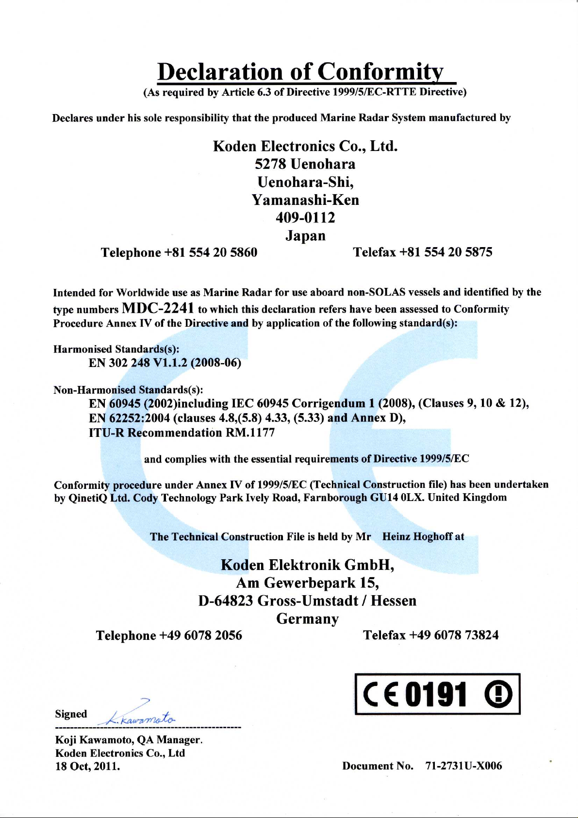
Declaration of Conformity
(As required by Article 6.3 of Directive 1999/5/EC-RTTE Directive)
Declares under his sole responsibility that the produced Marine Radar System manufactured
by
Koden Electronics Co., Ltd.
5278 Uenohara
Uenohara-Shi,
Yamanashi-Ken
409-0112
Japan
Telephone +81 554 20 5865 Telefax +81 554 20 5880
Intended for Worldwide use as a Marine Radar for use aboard non-SOLAS vessels and
identified by the type number
which this declaration refers has been tested to the essential radio test suites required by the
notified body and is in conformity with the standards
EN 60945 : 2002 ( Clauses 9,10 & 12 )
EN 62252 : 2004 ( Clauses 4.8, 4.33, 5.8, 5.33 and Annex D )
ITU-R Recommendation RM.1177
and complies with the essential requirements of Directive 1999/5/EC
Conformity procedure under Annex IV of 1999/5/EC (Technical Construction file) has been
undertaken by
QinetiQ Ltd. Cody Technology Park
The Technical Construction File is held by Mr Heinz Hoghoff at
MDC-2240 / MDC-2260 / MDC-2210 / MDC-2220 to
Ively Road, Farnborough GU14 0LX. United Kingdom
Koden Elektronik GmbH,
Am Gewerbepark 15,
D-64823 Gross-Umstadt / Hessen
Germany
Telephone +49 6078 2056 Telefax +49 6078 73824
Kenichi Chiwaki, QA Manager.
Koden Electronics Co., Ltd.
12 Jul. 2007
Notified Body : QinetiQ
Statement Number: QQ-RTTE-15/07-01
: QQ-RTTE-16/07-01
: QQ-RTTE-17/07-01
-
-
-
Page 3

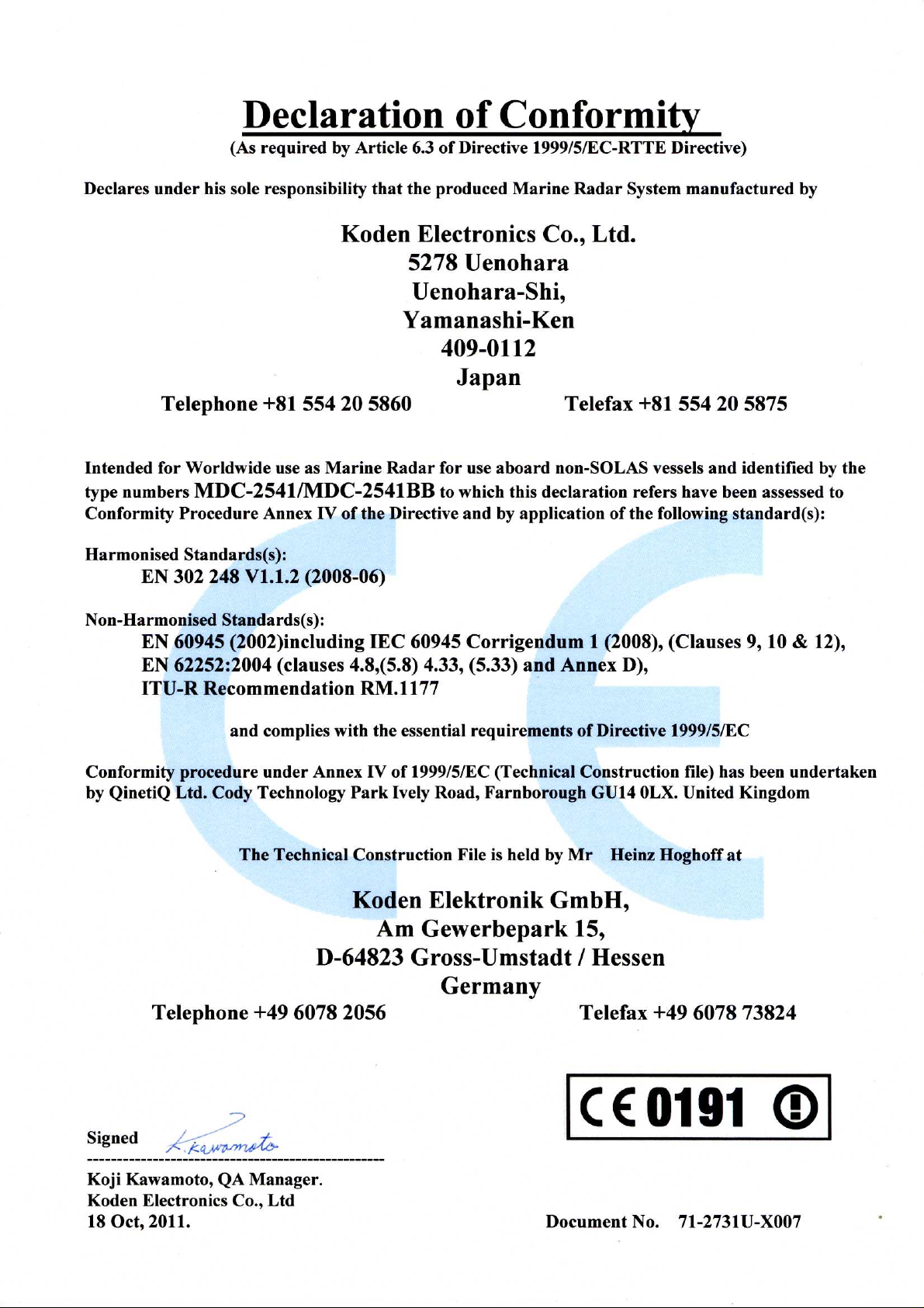
Declaration of Conformity
(As required by Article 6.3 of Directive 1999/5/EC-RTTE Directive)
Declares under his sole responsibility that the produced Marine Radar System manufactured
by
Koden Electronics Co., Ltd.
5278 Uenohara
Uenohara-Shi,
Yamanashi-Ken
409-0112
Japan
Telephone +81 554 20 5865 Telefax +81 554 20 5880
Intended for Worldwide use as a Marine Radar for use aboard non-SOLAS vessels and
identified by the type number
which this declaration refers has been tested to the essential radio test suites required by the
notified body and is in conformity with the standards
EN 60945 : 2002 ( Clauses 9,10 & 12 )
EN 62252 : 2004 ( Clauses 4.8, 4.33, 5.8, 5.33 and Annex D )
ITU-R Recommendation RM.1177
and complies with the essential requirements of Directive 1999/5/EC
Conformity procedure under Annex IV of 1999/5/EC (Technical Construction file) has been
undertaken by
QinetiQ Ltd. Cody Technology Park
The Technical Construction File is held by Mr Heinz Hoghoff at
MDC-2540 / MDC-2560 / MDC-2510 / MDC-2520 to
Ively Road, Farnborough GU14 0LX. United Kingdom
Koden Elektronik GmbH,
Am Gewerbepark 15,
D-64823 Gross-Umstadt / Hessen
Germany
Telephone +49 6078 2056 Telefax +49 6078 73824
Kenichi Chiwaki, QA Manager.
Koden Electronics Co., Ltd.
12 Jul. 2007
Notified Body : QinetiQ
Statement Number: QQ-RTTE-15/07-01
: QQ-RTTE-16/07-01
: QQ-RTTE-17/07-01
-
-
-
Page 4
Page 5
Page 6

MDC-2200/2500 Series
DC-2200/2500 Series Operation Manual
Doc No: 0093125002
Revision history in document
No.
0
1
2
3
4
5
Document No./Version No.
0093125002-00 03/09/2007 First edition
0093125002-01 29/10/2007 Cover
0093125002-02 23/10/2008 Total revision
0093125002-03 21/01/2010 Contents, Chapter 4, Chapter 7
0093125002-04 07/02/2012 Contents, Chapter1, Chapter 3, Chapter 4, Chapter7
0093125002-05 17/05/2012 Declaration, Chapter 4, Chapter5
6
7
8
9
Revised Date
Description
10
Revision criteria for document number/version number
If any contents of the document has been revised, the version number is altered on the cover
sheet and corresponding chapter revised, while the other chapters remain unchanged. The
document number is designated lower right in the cover sheet and at the left or right part of every
footer.
Prohibition of copy/reprint
No part of this manual shall be reprinted or copied by any means without written permission by
Koden Electronics Co., Ltd.
Disclaimer
The specifications and technical issues described in this manual are subject to change without
notice. Koden Electronics Co., Ltd. has no responsibility for any human and physical damage or
failure caused by the interpretive error of this manual.
Page 7

MDC-2200/2500 series Table of Contents
Contents
Chapter 1 Preface .................................................................................................... 1-1
1.1 About this operation manual .................................................................................... 1-1
For safe usage ......................................................................................................... 1-2
1.2
1.3
Disposal of used cell and this device ....................................................................... 1-4
...................................................................... 1-4
1.4
1.5
Treatment of the used lithium ion cell
Disposal of this device
Principal features of this device ............................................................................... 1-4
In case no Heading and Speed signals are input from navigation equipment..........1-5
............................................................................................. 1-4
Chapter 2 Function and control names .................................................................... 2-1
2.1 Radar screen .................................................................................................................. 2-1
2.2 Control panel
................................................................................................................... 2-2
Chapter 3 Basic operation (For Control panel) ......................................................... 3-1
3.1 Power On/Off .................................................................................................................. 3-1
Power On
Power Off
3.2 Change brilliance of display unit (Screen and Control panel)
Change screen brilliance
Change brightness of control panel dimmer
3.3 Transmission
................................................................................................................. 3-1
................................................................................................................. 3-1
........................................ 3-1
.......................................................................................... 3-1
............................................................ 3-2
................................................................................................................... 3-2
Start transmission
Stop transmission
3.4 Change range (indicated distance)
3.5 Adjust receiver gain (GAIN)
3.6 Reduce sea clutter (STC)
3.7 Reduce rain/snosion pulse length (SP/LP)
3.9 Enhance target (w clutter (FTC)
3.8 Change transmisENH)
3.10 Measure distance and bearing of a target
Measure distance (VRM)
Measure bearing (EBL)
Measure distance/bearing (Parallel index line)
Measure distance and bearing between two points (Offset)
3.11 Change echo color (DAY/NIGHT)
3.12 Remove the heading line
..................................................................................................... 3-2
..................................................................................................... 3-3
................................................................................. 3-3
............................................................................................ 3-4
............................................................................................... 3-5
..................................................................................... 3-7
.................................................................................................... 3-7
.......................................................................................... 3-8
............................................................................................ 3-9
............................................................................... 3-14
............................................................................................ 3-14
..................................................................... 3-7
.................................................................... 3-8
...................................................... 3-10
.................................. 3-13
0093125002-04 i
Page 8

Table of Contents MDC-2200/2500 Series
3.13 Relocate own ship position (Off-centering)
3.14 Select display mode
For H UP (Head up mode)
For C UP (Course up mode)
For N UP (North up mode)
For relative motion (RM) and true motion (TM)
Reset true motion
3.15 Use ATA/EPA
Manual acquisition
Delete target (Select and delete)
Delete all targets
Use Automatic acquisition (Up to 40 targets can be acquired in default)
Detailed target display method
Other setting
EPA operation method
Update EPA
Types and meaning of ATA/EPA symbol
............................................................................................................... 3-20
.................................................................................................... 3-16
......................................................................................3-16
...................................................................................3-17
.....................................................................................3-17
...................................................................................................3-19
..................................................................................................3-20
............................................................................3-21
.....................................................................................................3-21
...............................................................................3-23
...........................................................................................................3-24
............................................................................................3-25
............................................................................................................3-26
................................................................. 3-15
......................................................3-18
...............3-21
.................................................................3-27
3.16 Use F (Function key)
For short cut menu
Position data output
................................................................................................... 3-28
.................................................................................................3-28
................................................................................................3-29
Chapter 4 Menu operations ......................................................................................4-1
4.1 How to see and use Menu .............................................................................................. 4-1
Display menu (main menu)
Delete menu
Select menu item.
Determine setting
Display detailed menu
4.2 MARKER menu
(1) Display Range rings
(2) Set bearing mode (relative/true mode)
(3) Marker selection (MDC-2200 only)
(4) Designate display lines of Parallel index
(5) Designate display direction of Parallel index
............................................................................................................. 4-1
..................................................................................................... 4-1
..................................................................................................... 4-2
............................................................................................................... 4-3
....................................................................................... 4-1
.............................................................................................. 4-2
............................................................................................ 4-3
............................................................... 4-4
................................................................. 4-4
............................................................. 4-4
...................................................... 4-4
(6) Designate cross cursor display method
(7) VRM1 Setting of range unit
(8) VRM2 Setting of range unit
(9) PI Setting of range unit
(10) Display stern marker
0093125002-04 ii
................................................................................. 4-6
................................................................................. 4-6
........................................................................................ 4-6
......................................................................................... 4-6
.............................................................. 4-5
Page 9

MDC-2200/2500 series Table of Contents
(11) Setting of cursor shape
(12) Tracking cursor
(13) HU bearing interlocking
(14) Display VRM/EBL intersection
(15) Display bearing scale
(16) Display bearing in numerical value or with symbol on the bearing scale
(17) Select bearing display location
(18) Select display format
(19) Use blinking of heading line
(20) Display guard line
(21) Display own ship’s outline
(22) Setup own ship’s profile (Cannot use on transmitting)
(23) Display/generate own ship’s profile
4.3 ECHO menu
(1) Select display mode
(2) Display trail
(3) Select trail display mode (relative or true)
..................................................................................... 4-6
................................................................................................. 4-6
.................................................................................... 4-7
.......................................................................... 4-7
........................................................................................ 4-7
......... 4-7
......................................................................... 4-7
........................................................................................ 4-7
.............................................................................. 4-8
............................................................................................. 4-8
................................................................................. 4-8
................................... 4-8
.................................................................. 4-9
.................................................................................................................. 4-10
.......................................................................................... 4-11
....................................................................................................... 4-11
........................................................ 4-11
(4) Select trail color (Blue or Red)
(5) Select trail display shape
(6) Sustain range
(7) Time keep
(8) Switching of base input sensor in true motion (Course or Position)
(9) Rel mode
(10) Trail detection level (1 to 6)
(11) Interference rejection (IR)
(12) Display target stable using signal processing
(13) Switch over Day/Night mode
(14) Daytime Echo color selection (Change Daytime mode color)
(15) Night Echo color selection (Change Night mode color)
(16) Daytime background color selection
(17) Night background color selection
(18) Enlarge cursor position image by zooming function
(19) Reset true motion
(20) True motion reset position
.......................................................................... 4-13
.................................................................................. 4-13
.................................................................................................... 4-13
.......................................................................................................4-13
................. 4-13
........................................................................................................4-14
............................................................................. 4-14
............................................................................... 4-14
................................................. 4-14
.......................................................................... 4-15
........................ 4-15
.................................. 4-15
............................................................. 4-15
.................................................................... 4-15
....................................... 4-15
........................................................................................... 4-15
.............................................................................. 4-16
(21) Fixed Image
(22) Sector scan
(23) Designate range unit (NM, km, sm)
(24) Designate rotation angle
(25) Designate rotation speed
0093125002-04 iii
.................................................................................................... 4-16
..................................................................................................... 4-16
................................................................ 4-16
................................................................................. 4-16
................................................................................ 4-16
Page 10

Table of Contents MDC-2200/2500 Series
(26) Full screen display
(27) Off center position
4.4 NAV menu
(1) Select stabilization base (SEA/GND)
(2) Set up tide bearing
(3) Set up tide speed
(4) Set up vector display time
(5) Set up vector display mode
(6) Use navline
(7) Select block no. of navline
(8) Delete navline by designating block no.
(9) Set up detection function
(10) Input/edit navline data
4.5 ALARM menu
(1) Use guard zone
(2) Setup CPA
(3) Setup TCPA
..................................................................................................................... 4-18
..........................................................................................4-17
...........................................................................................4-17
................................................................4-18
............................................................................................4-18
..............................................................................................4-18
.................................................................................4-18
...............................................................................4-19
.......................................................................................................4-19
................................................................................4-19
............................................................4-19
..................................................................................4-19
.....................................................................................4-19
................................................................................................................ 4-20
.................................................................................................4-20
.........................................................................................................4-22
.......................................................................................................4-22
(4) Setup ATA buzzer sound
(5) Setup AIS buzzer sound
(6) Use Alarm 1
(7) Setup Alarm 1 detection mode
(8) Setup Alarm 1 detection level
(9) Setup Alarm 1 area setting method
(10) Use Alarm 2
(11) Select Alarm 2 block number
(12) Delete registered data by designating block number
(13) Select Alarm 2 detection method
(14) Setup Alarm 2 detection level
(15) Input/edit Alarm 2 data
Delete alarm sound
4.6 ATA/EPA menu
(1) Select ATA function or EPA function
(2) Manual target acquisition
(3) Select acquired target and delete it
...................................................................................4-22
....................................................................................4-22
.......................................................................................................4-22
..........................................................................4-24
...........................................................................4-24
...................................................................4-24
.....................................................................................................4-24
...........................................................................4-24
......................................4-25
....................................................................4-25
.........................................................................4-25
....................................................................................4-25
................................................................................................4-26
.............................................................................................................. 4-27
..................................................................4-27
..................................................................................4-27
..................................................................4-27
(4) Delete all acquired targets
(5) Setting method for acquiring number manually
(6) Auto acquisition
(7) Set up target ID display
(8) ID size
0093125002-04 iv
...............................................................................................................4-28
.................................................................................................4-28
................................................................................4-28
................................................4-28
.....................................................................................4-28
Page 11

MDC-2200/2500 series Table of Contents
(9) Select target
(10) EPA Update
(11) Data display format
4.7 AIS menu (Optional AIS unit required)
(1) Activate AIS display
(2) Set up target ID display
(3) Select target
(4) Setup detection area (Display area setup)
(5) Setup lost target display
(6) Setup sleep ship display
(7) Setup class B target display
(8) Setup ATON target display
(9) Setup SART target display
(10) Setup BASE target display
(11) Auto acquisition ring
Type and meaning of AIS symbols
4.8 CHART menu
...................................................................................................... 4-28
..................................................................................................... 4-28
......................................................................................... 4-29
.......................................................................................... 4-30
.................................................................................... 4-30
...................................................................................................... 4-31
................................................................................... 4-31
................................................................................... 4-31
................................................................................ 4-31
................................................................................ 4-32
........................................................................................4-32
................................................................................................................ 4-33
.......................................................................... 4-30
....................................................... 4-31
............................................................................. 4-31
............................................................................. 4-32
......................................................................... 4-32
(1) Display/hide chart
Insert method of C-MAP chart card
Chart card removal
(2) Setup own ship track, ATA target track, and AIS target track
(3) Setup track memory interval
(4) Delete track
(5) Setup Way point/route
(6) Display mark
(7) Select block number for mark display
(8) Delete mark data of specified block number
(9) Display line from own ship location to mark
(10) Select display mark shape
(11) Input mark (own ship position)
(12) Mark input/delete (cursor position)
(13) Input/edit mark (latitude/longitude input)
(14) All marks display
(15) Select chart
............................................................................................. 4-34
........................................................................ 4-34
................................................................................................. 4-35
............................................................................. 4-36
....................................................................................................... 4-36
...................................................................................... 4-36
..................................................................................................... 4-36
............................................................... 4-36
.................................................... 4-37
..................................................... 4-37
.............................................................................. 4-37
........................................................................ 4-37
................................................................. 4-38
........................................................ 4-38
............................................................................................. 4-38
..................................................................................................... 4-38
........................... 4-35
(16) Detail chart display setting
(17) Accommodate radar image and chart display (position compensation)
(18) Correct latitude
(19) Correct longitude
(20) Display Waypoint/Route ID
0093125002-04 v
................................................................................................ 4-39
............................................................................................. 4-39
.............................................................................. 4-39
......... 4-39
............................................................................. 4-39
Page 12

Table of Contents MDC-2200/2500 Series
(21) Display flag mark on waypoint
(22) Select COAST LINE/GPS BUOY
(23) Using of COAST LINE
(24) Using of GPS buoys
4.9 DATADISP menu
(1) Upper display setting
(2) Lower display area background color setting
(3) Setup DISP1 display item
(4) Setup DISP2 display item
(5) Setup DISP3 display item
(6) Protect cancel
4.10 STARTUP menu
(1) Tuning method
(2) Auto tune setting
(3) Manual tune setting
(4) Bearing setting
(5) Range adjustment
........................................................................4-39
....................................................................4-40
.....................................................................................4-40
........................................................................................4-40
........................................................................................................... 4-42
.........................................................................................4-42
...................................................4-42
.................................................................................4-43
.................................................................................4-43
.................................................................................4-43
...................................................................................................4-43
.......................................................................................................... 4-44
..................................................................................................4-44
...............................................................................................4-44
...........................................................................................4-44
..................................................................................................4-44
.............................................................................................4-44
(6) STC curve
(7) Main Bang Suppression
(8)(9)(10) F key setting
(11) RAIN key setting
(12) SEA key setting
(13) GAIN key setting
4.11 I/O menu
4.12 SYSTEM menu
...................................................................................................................... 4-46
(1) Heading bearing
(2) Ship speed
(3) COG/SOG
(4) Latitude/longitude
(5) Ground stabilization setting
(6) Output (J4,J5)
(7) Baud rate
(8) Input
(1) LANG
..................................................................................................................4-47
.................................................................................................................4-48
.........................................................................................................4-45
....................................................................................4-45
...........................................................................................4-45
..............................................................................................4-45
...............................................................................................4-45
.............................................................................................4-45
................................................................................................4-46
........................................................................................................4-46
.........................................................................................................4-46
..............................................................................................4-46
...............................................................................4-46
...................................................................................................4-46
...........................................................................................................4-47
........................................................................................................... 4-48
4.13 PRESET menu
0093125002-04 vi
(2) Buzzer sound
(3) Buzzer sound frequency
(4) Key click
(5) External buzzer
....................................................................................................4-48
............................................................................................................4-48
.................................................................................................4-48
............................................................................................................ 4-49
...................................................................................4-48
Page 13

MDC-2200/2500 series Table of Contents
(1) Gain manual
(2) Manual STC maximum
(3) Manual STC minimum
(4) STC curve
(5) FTC manual selection
(6) Main Bang Suppression
(7) Target level
(8) ATA performance
(9) Video mode
4.14 CONTRAST menu
4.15 BITE menu
(1) Alarm test
(2) ATA test
(3) Total operating hours
(4) Transmitting hours
(5) Panel test
(6) Monitor
.................................................................................................................. 4-52
.......................................................................................................... 4-52
............................................................................................................. 4-52
.......................................................................................................... 4-53
.............................................................................................................. 4-53
...................................................................................................... 4-49
..................................................................................... 4-49
...................................................................................... 4-49
......................................................................................................... 4-49
....................................................................................... 4-50
.................................................................................... 4-50
........................................................................................................ 4-50
...............................................................................................4-50
....................................................................................................... 4-50
...................................................................................................... 4-51
........................................................................................ 4-52
............................................................................................ 4-52
(7) Monitor No. selection
(8) ATA diagnose
(9) AIS diagnose
(10) Version
4.16 ANTENNA menu
(1) High voltage
(2) Mag current
(3) Mag heater voltage
(4) Tune voltage
(5) Antenna unit type
(6) Antenna unit communication status
4.17 OPTION menu
(1) Inter-switch
(2) Antennal location designation
(3) Echo offset
(4) Heading offset
(5) Antenna high speed rotation
........................................................................................ 4-53
.................................................................................................... 4-53
..................................................................................................... 4-53
............................................................................................................ 4-53
......................................................................................................... 4-54
...................................................................................................... 4-54
....................................................................................................... 4-54
........................................................................................... 4-54
..................................................................................................... 4-54
.............................................................................................. 4-54
.................................................................. 4-54
............................................................................................................ 4-55
........................................................................................................ 4-55
........................................................................... 4-55
........................................................................................................ 4-55
................................................................................................... 4-55
............................................................................. 4-55
(6) Display information
(7) Ferry mode
(8) Length unit
4.18 INITIAL menu
(1) Readout of setup items
0093125002-04 vii
........................................................................................................4-56
.........................................................................................................4-57
.............................................................................................................. 4-58
........................................................................................... 4-56
..................................................................................... 4-58
Page 14

Table of Contents MDC-2200/2500 Series
(2) Setup save
(3) External load
(4) External save
(5) System program load
(6) ATA program load
(7) AIS program load
(8) Mark load
(9) Mark save
(10) Past load
(11) Past save
(12) Preset load
4.19 Menu configuration
........................................................................................................4-58
......................................................................................................4-59
.....................................................................................................4-59
........................................................................................4-59
..............................................................................................4-59
...............................................................................................4-59
...........................................................................................................4-59
..........................................................................................................4-59
..........................................................................................................4-59
.........................................................................................................4-59
......................................................................................................4-60
......................................................................................................4-61
Chapter 5 Specification and configurations............................................................... 5-1
5.1 Antenna ........................................................................................................................... 5-1
5.2 Display unit
5.3 Configuration items
...................................................................................................................... 5-1
......................................................................................................... 5-2
Standard configuration
Options
5.4 External view and dimensions
..................................................................................................................... 5-2
.............................................................................................. 5-2
........................................................................................ 5-3
Chapter 6 Principle of radar system.......................................................................... 6-1
6.1 What is radar system? ....................................................................................................6-1
Side lobe
Beam width
6.2 Characteristics of radar radio wave
Target hardness reflected
Radar shadow
False image
6.3 Radar interference
................................................................................................................... 6-1
............................................................................................................... 6-2
................................................................................ 6-2
......................................................................................... 6-2
.......................................................................................................... 6-3
.............................................................................................................. 6-3
.......................................................................................................... 6-5
Chapter 7 Index ........................................................................................................ 7-1
0093125002-04 viii
Page 15
MDC-2200/2500 Series Chapter 1 Preface
Chapter 1 Preface
1.1 About this operation manual
First of all, Koden Electronics CO., Ltd. would like to express our sincere gratitude for your
purchase of this MDC-2200/2500 series Radar.
This operation manual (hereinafter referred to as “this document”) describes operations and
maintenance of the radar systems MDC-2200/2500 series (hereinafter referred to as “this device”.)
Please keep this document in the location near the device to refer at any time when required.
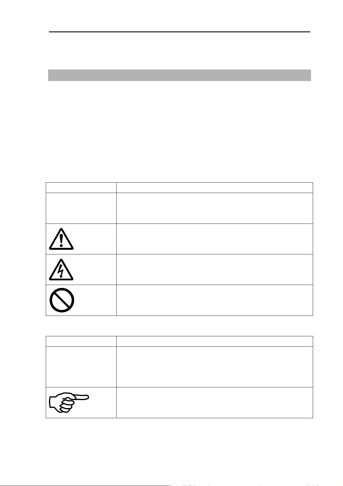
The following symbol is displayed on the important part of safety usage of this device among this
description. The way as a symbol and the semantics are as follows.
Symbol Meaning
Mark for warning
Warning
Caution
The following symbol is attached to important information among the descriptions in this document.
Symbol Meaning
IMPORTANT
This symbol denotes that there is a risk of death or serious injury when
not dealing with it correctly.
Mark for caution
This symbol denotes that there is a risk of slight injury or damage of
device when not dealing with it correctly.
Mark for danger high voltage
This symbol denotes that there is a risk of death or serious injury
caused by electric shock when not dealing with it correctly.
Mark for prohibition
This symbol denotes prohibition of the specified conduct. Description of
the prohibition is displayed near the mark.
Mark for important matters
This mark denotes that there is a possibility that data loss may interfere
the operation or that the expected result may not be obtained when not
dealing with it correctly.
Mark for reference
This mark shows the part to be referred related to this description.
0093125002-04 1-1
Page 16
Chapter 1 Preface MDC-2200/2500 Series
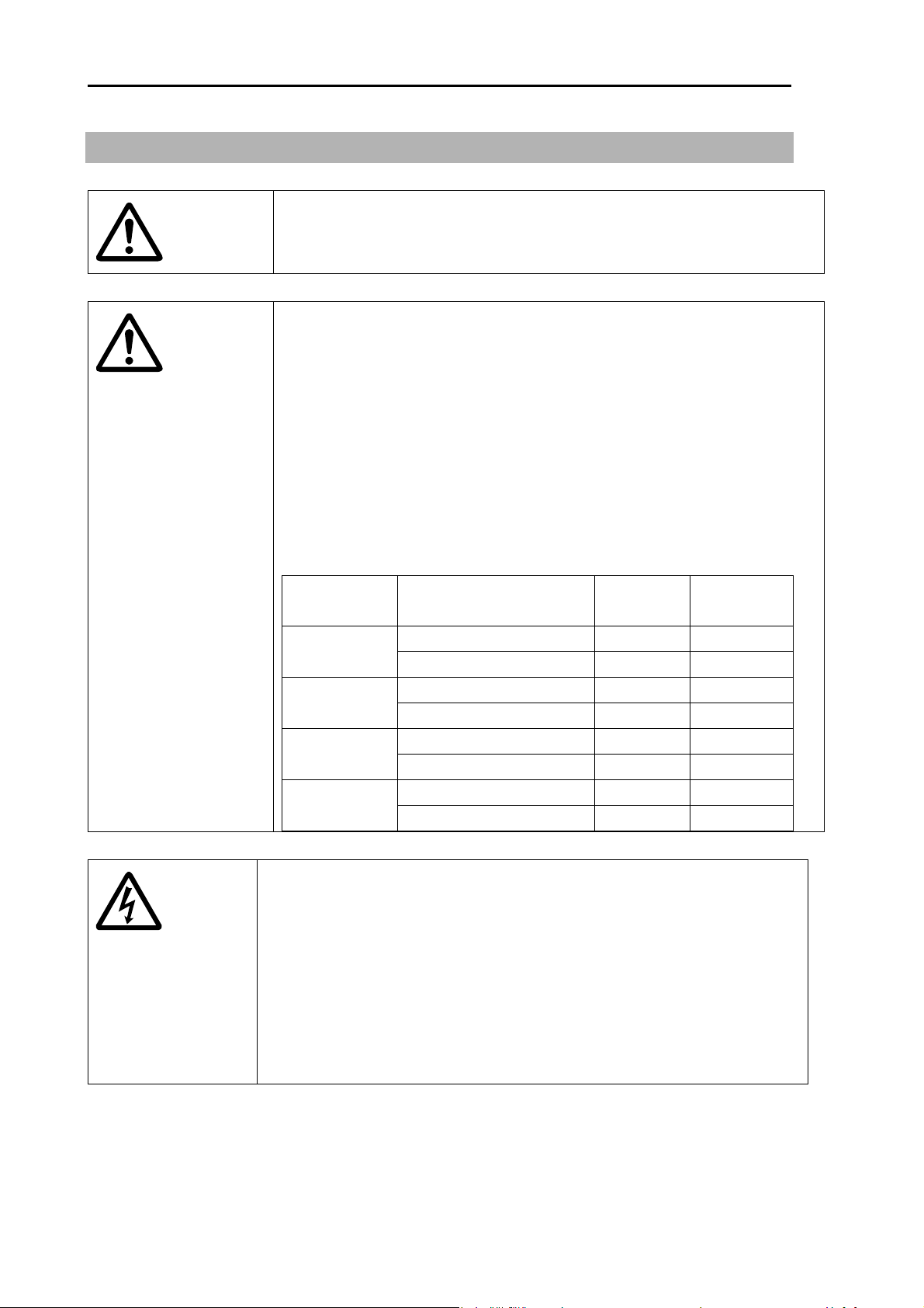
1.2 For safe usage
Caution about the rotating aerial
Caution
Caution
The radar antenna may start to rotate without notice. Please stand clear
from the antenna for your safety.
Caution about electromagnetic disturbance
The operating antenna & scanner unit radiates high-energy
electromagnetic wave. It may cause harmful effect for human body due to
its continuous irradiation. As International regulation says, electromagnetic
waves less than 100 watt/m
bodies, but some kind of medical devices such as heart pacemakers are
sensitive even under the low energy electromagnetic wave. Any personnel
with such a device should keep away from the electromagnetic wave
generating position at all times.
Specified power density and distance from the device (in accordance with
the provision as specified in IEC 60945)
Model name Output power/
Antenna length
4kW / 3 feet Antenna 0.9m 2.85m MDC-2240
/MDC-2540
/MDC-2560
/MDC-2510
/MDC-2520
4kW / 4 feet Antenna 1.01m 3.2m
6kW / 4 feet Antenna 1.09m 3.46m MDC-2260
6kW / 6 feet Antenna 1.3m 4.10m
12kW / 4 feet Antenna 1.55m 4.89m MDC-2210
12kW / 6 feet Antenna 1.84m 5.81m
25kW / 6 feet Antenna 2.82m 8.91m MDC-2220
25kW / 9 feet Antenna 3.35m 10.6m
2
does not have a harmful effect on human
100W/m
2
10W/m2
Caution about internal high voltage.
Confirm that the ship’s power source and power supply of this device is
0093125002-04 1-2
turned off when doing an internal inspection of this device.
The maintenance and inspection of these devices should be performed by
qualified technical personnel.
Post the notice of “During inspection” label near the power switch of this
device during service and inspecting.
High voltage is used inside this device. This high voltage may remain in
the circuit even after the power switch had turned off.
Page 17

MDC-2200/2500 Series Chapter 1 Preface
Caution against the dust
Warning
Caution
Please wear a safety mask in the case of cleaning the interior of the
device. Dust may temporarily cause a disease of the respiratory
system. Be careful not to inhale dust.
Caution against static electricity
Please handle the printed circuit board only after taking measures
against static electricity. Static electricity occurs from the carpet on
the floor of the cabin, etc. and clothes made of synthetic fiber and
may damage the electronic parts on the printed circuit board.
0093125002-04 1-3
Page 18

Chapter 1 Preface MDC-2200/2500 Series
1.3 Disposal of used cell and this device
A high-energy density lithium ion cell is built in this device.
Warning
Improper disposal of a lithium ion cell is discouraged as the cell has a
possibility of short-circuiting. If it gets wet, the generation of heat,
explosion or ignition may occur resulting in an injury or a fire.
Treatment of the used lithium ion cell
To dispose of built-in lithium ion cell in this device, insulate each terminal with scotch tape, etc. and
wrap in plastic bag, etc.
The disposal and collection rules may be different depending on each country. Obey the directions
of each country.
Disposal of this device
This device shall be disposed according to the regulations or rules.
1.4 Principal features of this device
The MDC-2540/2560/2510/2520 type Radar system is a compact and high performance shipboard
radar system consisting of the antenna & scanner unit with a transmit power of 4kW/6kW/12kW/25kW,
a display unit with a 15 inch color LCD display and operating panel unit. The MDC-2240/2260/2210/
2220 type Radar system is the system which consists of the antenna & scanner unit with the transmit
power 4kW/6kW/12kW/25kW and display unit with 12.1 inch color LCD display.
For this device, its multi functions and high performance is accomplished with microcomputer
technology as well as an image processing in the newly developed radar-dedicated LSI.
A slim display unit using liquid crystal technology.
Stable indication and reliable acquisition of small target.
Clear distinction between moving target and land by true trail display.
Provision of multi targets ATA information and the chart display (mandatory or optional).
Various models for selection of an optimum device for your needs.
Simple and easy operation by user-friendly rotating knobs.
Capable of adjusting gain, anti- sea clutter, anti- rain clutter, bearing cursor, and range marker, etc.
using rotating knobs.
The waterproof (IPX5) display unit and operating panel have a great flexibility in installation.
0093125002-04 1-4
Page 19

MDC-2200/2500 Series Chapter 1 Preface
1.5 In case no Heading and Speed signals are input from
navigation equipment
When no Heading and Speed signals are input from navigation equipment (in case not connected), this
radar gives alarms and warning messages on the screen, if the radar is started up by factory default
settings.
These alarms are disengaged by pressing “OFF” key temporarily, however, the alarms are activated
again next time the radar is started up.
Disengage the alarm detection function on start up by the following setting. Once set, the alarm is not
detected next time the radar is started up.
MENU => DATADISP => PROTECT CANCEL => ENT
MENU => NAV => STAB => GND => SEA => ENT
NAV => VECTOR TRUE/REL => TRUE => REL => ENT
I/O => HDG => HDG => ON => OFF => ENT
I/O => SPD => SPD => ON => OFF => ENT
0093125002-04 1-5
Page 20
MDC-2200/2500 Series Chapter 2 Function and control names
Chapter 2 Function and control names
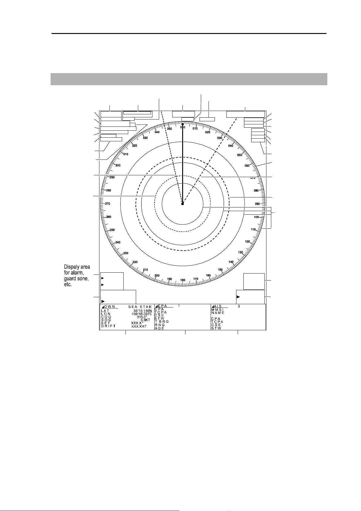
2.1 Radar screen
Own ship speed
1
0
°
7
.
0
0.8kn
Fixing of image
Upper display
O W N
H O L D
15.146N
35°
45.037E
139°
GAIN MAN
SEA MAN
RAIN MAN
ENH3
PROC1
VD1
Gain
Anti-sea clutter
Anti-rain clutter
IR4
Interference rejection
Enhance target
Signal processing
Video
Bearing scale
RR interval
Dispaly mode
TRAILS
Off center
Zoom
X-band
Trail mode
Range
0.75
0.125 NM M1WP
H UP RM (T)
T R A I L S
O F F C E N T
Z O O M
X - B A N D
AUTO
CONT
TX pulse length
HeadingTune
EBL1
VRM1
EBL2
VRM2
Range rings
EBL
GZ
B R G
W I D T H
R N G
D E P T H
E B L 2 T R U E
000.0°
000.0°
Lower display
DISP1
Lower display
DISP2
Lower display
139°45.037E
V R M 1
000.0NM
000.0NM
DISP3
CURSOR
000.0°
0.000NM
15.146N
35°
Cursor
VRM
0093125002-02 2-1
Page 21
Chapter 2 Function and control names MDC-2200/2500 Series
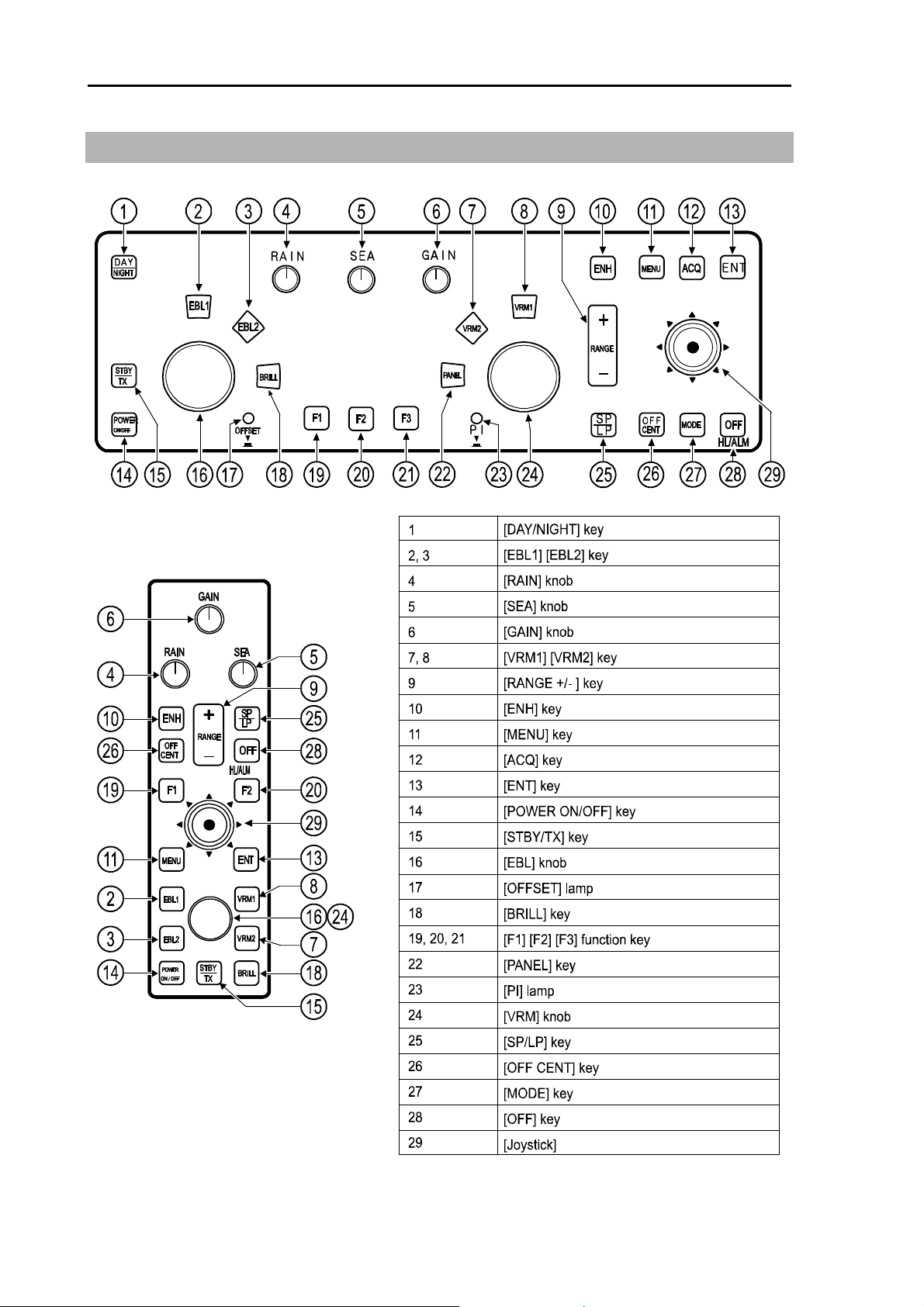
2.2 Control panel
MDC-2500 Series
MDC-2200 Series
0093125002-02 2-2
Page 22

MDC-2200/2500 Series Chapter 2 Function and control names
1 [DAY/NIGHT] key Note: This function is not available for MDC-2200
Change video and background color. 2 types of mode are provided for day and night.
2 [EBL1] key
This key is used to switch on or off EBL1. This key is used to switch operation when EBL2 is
selected and displayed.
3 [EBL2] key
This key is used to switch on or off display of EBL2. This key is used to switch operation
when EBL1 is selected and displayed.
4 [RAIN] knob
This knob is used to adjust to reduce reflection of rain and snow to improve target
delectability. Rain and snow reflection reduction effect is increased by turning knob to the
clockwise direction. It is also used as function key by pressing knob.
5 [SEA] knob
This knob is used to adjust to reduce reflection of ripple of sea surface to improve target
delectability.
Surface reflection reduction effect is increased by turning knob to the clockwise direction. It is
also used as function key by pressing knob.
6 [GAIN] knob
This knob is used to adjust receiving gain to improve target delectability. Gain is increased by
turning knob clockwise. It is also used as function key by pressing knob. It is also used as
function key by pressing knob.
7 [VRM1] key
This key is used to switch on or off VRM1. It is also used to switch operation when VRM2 is
displayed and selected.
8 [VRM2] key
This key is used to switch on or off VRM2. It is also used to switch operation when VRM1 is
displayed and selected.
9 [RANGE] key
The RANGE key changes the range scale. A press of the + key or – key increases or
decreases the range scale, respectively.
10 [ENH] key
Target enhance function is switched by pressing this key, [ENH 1] => [ENH 2] => [ENH 3] =>
Off
0093125002-02 2-3
Page 23

Chapter 2 Function and control names MDC-2200/2500 Series
11 [MENU] key
Menu is turned on or off by pressing this key.
12 [ACQ] key Note: This function is not available for MDC-2200.
This key is used for target acquisition of ATA or EPA.
Acquired target is deleted when [OFF] and [ACQ] keys are pressed simultaneously.
13 [ENT] key
This key is used to determine designated value for menu operation. Designated value is not
altered if menu is closed without pressing [ENT] key. This key is also used to select target of
ATA, EPA or AIS and to select mark during mark display.
14 [POWER ON/OFF] key
This key is used to turn power on or off.
15 [STBY/TX] key
This key is used to switch on TX or standby.
16 [EBL] knob Note: [EBL]/ [VRM] knobs are common for MDC-2200.
This knob is used to operate EBL or to adjust screen brilliance.
Offset function is activated when this knob is pressed.
17 [OFFSET] lamp Note: This function is not available for MDC-2200.
This lamp is on when offset function is active.
18 [BRILL] key
This key is used to change screen brilliance.
19 [F1] function key
This key is used for function key. Function assignment is selected in startup menu.
20 [F2] function key
This key is used for function key. Function assignment is selected in startup menu.
0093125002-02 2-4
Page 24

MDC-2200/2500 Series Chapter 2 Function and control names
21 [F3] function key Note: This function is not available for MDC-2200.
This key is used for function key. Function assignment is selected in startup menu.
22 [PANEL] key Note: Panel dimmer is changed over by [BRILL] key for MDC-2200.
This key is used to change panel dimmer.
23 [PI] lamp Note: This function is not available for MDC-2200.
This lamp is on during parallel index line function is selected.
24 [VRM] knob Note: [EBL] / [VRM] knobs are common for MDC-2200.
This knob is used to operate VRM or to adjust panel dimmer.
25 [SP/LP] key
This key is used to change pulse length to improve target delectability.
26 [OFF CENT] key
This key is used to switch on or off Off center.
27 [MODE] key Note: This function is not available for MDC-2200.
This key is used to switch over display mode such as Head-up, North-up etc.
28 [OFF] key
Heading line is erased during this key is pressed.
Alarm sound is stopped by pressing this key at the time when alarm is sounding.
Deleting operation is performed by using this key in combination with other keys.
29 [Joy stick]
This device is used for cross cursor operation, menu operation, target acquisition operation
or mark input operation.
0093125002-02 2-5
Page 25

MDC-2200/2500 Series Chapter 3 Basic operation
r
r
Chapter 3 Basic operation (for control panel)
3.1 Power On/Off
Power On
Press [POWER ON/OFF] key. Buzzer sound [Peep] is produced and then Radar system is activated.
・ After activation, the character of [Model name] and [WAIT] will be displayed and the preheating of
magnetron will start.
・The brilliance of the screen is set with the brilliance set at the time when the power has been turned
off.
Power Off
Keep pressing [POWER ON/OFF] key for longer than 3 sec.
IMPORTANT: Re-entry of power shall be performed after having passed for longer than
3 sec. after power-off.
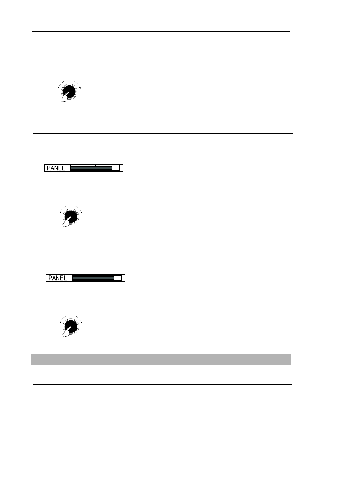
3.2 Change brilliance of display unit (Screen and Control panel)
Change screen brilliance
(For MDC-2200)
1 Press [BRILL] key. (Note: Each time [BRILL] key is pressed, it changes over “Screen brilliance”
and “Panel dimmer”)
2 Screen brilliance adjustment window is displayed.
3 Turn [EBL] / [VRM] knob clockwise to increase brilliance.
Turn [EBL] / [VRM] knob counter clockwise to decrease brilliance.
* The display brilliance changes in 5 steps each time by pressing [EBL] / [VRM] knob.
Darke
Brighte
Push
(For MDC-2500)
EBL / VRM knob
1 Press [BRILL] key.
2 Screen brilliance adjustment window is displayed.
0093125002-04 3-1
Page 26
Chapter 3 Basic operation MDC-2200/2500 Series
r
r
r
r
r
3 Turn [EBL] knob clockwise to increase brilliance.
Turn [EBL] knob counter clockwise to decrease brilliance.
* The display brilliance changes in 5 steps each time by pressing [EBL] knob.
Darker
Brighte
Push
EBL knob
Change brightness of control panel dimmer
(For MDC-2200)
1 Press [BRILL] key twice. (Press once during screen brilliance window is displayed.)
2 Panel dimmer adjustment window is displayed in the screen.
3 Turn [EBL] / [VRM] knob clockwise to increase brightness of the panel dimmer.
Turn [EBL] / [VRM] knob counter clockwise to decrease brightness of the panel dimmer.
* The panel dimmer changes in 5 steps each time by pressing [EBL] / [VRM] knob.
Darke
Push
Brighte
EBL / VRM knob
(For MDC-2500)
1 Press [PANEL] key.
2 Panel dimmer adjustment window is displayed in the screen.
3 Turn [VRM] knob clockwise to increase brightness of the panel dimmer.
Turn [VRM] knob counter clockwise to decrease brightness of the panel dimmer.
* The panel dimmer changes in 5 steps each time by pressing [VRM] knob.
Darke
Push
Brighte
VRM knob
3.3 Transmission
Start transmission
Press [STBY/TX] key. Antenna starts rotating and transmission.
Transmission is not available just after the power on and [WAIT] is displayed on the screen. Wait until
[STAND-BY] is displayed after timer count is completed.
0093125002-04 3-2
Page 27
MDC-2200/2500 Series Chapter 3 Basic operation
Stop transmission
Press [STBY/TX] key in [Transmission] status to stop transmission.
[STAND-BY] is displayed on the screen after stopping transmission.
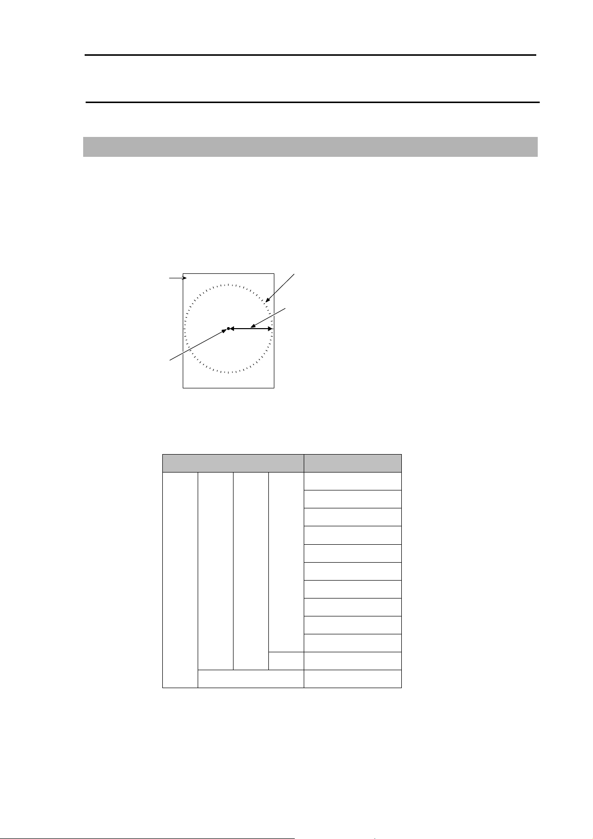
3.4 Change range (indicated distance)
By switching over range, observing area can be changed. Set up the most suitable range for
observation. The observing range is numerically displayed on the upper left of the screen.
1 Press [RANGE +] key to zoom out the area and to observe a long distance.
Press [RANGE -] key to zoom in the area and to magnify proximity of own ship to observe.
Bearing scale
Indicated distance
Range
Own ship
1.5
Ranges usable per each model are as shown below. (Standard setting)
Model name Range
MDC-2240/2540
MDC-2220/2520
MDC-2210/2510
MDC-2260/2560
(Max. output : 12 kW)
(Max. output : 6 kW)
(Max. output : 4 kW)
(Max. output : 25 kW)
0.125NM
0.25NM
0.5NM
0.75NM
1.5NM
3NM
6NM
12NM
24NM
48NM
72NM
96NM
0093125002-04 3-3
Page 28
Chapter 3 Basic operation MDC-2200/2500 Series
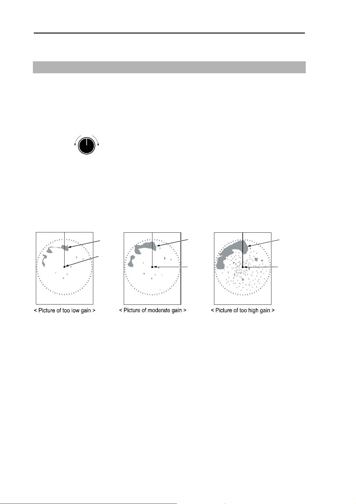
3.5 Adjust receiver gain (GAIN)
Adjust receiver gain with [GAIN] knob to obtain easy viewing screen according to observing status such
as range of distance, sea surface, rain and snow clutter, etc.
1 Turn [GAIN] knob clockwise to increase receiving gain.
Turn [GAIN] knob counter clockwise to decrease receiving gain.
Gain
Down
・ Decrease gain to observe short range dense targets easier.
・ Increase gain effectively for long range targets, however if gain is increased to much, the noise will
increase accordingly and it makes difficult to observe small targets.
Up
Result picture after adjustment by gain knob
Land
Own
ship
Land
Own
ship
Land
Own
ship
0093125002-04 3-4
Page 29
MDC-2200/2500 Series Chapter 3 Basic operation
A
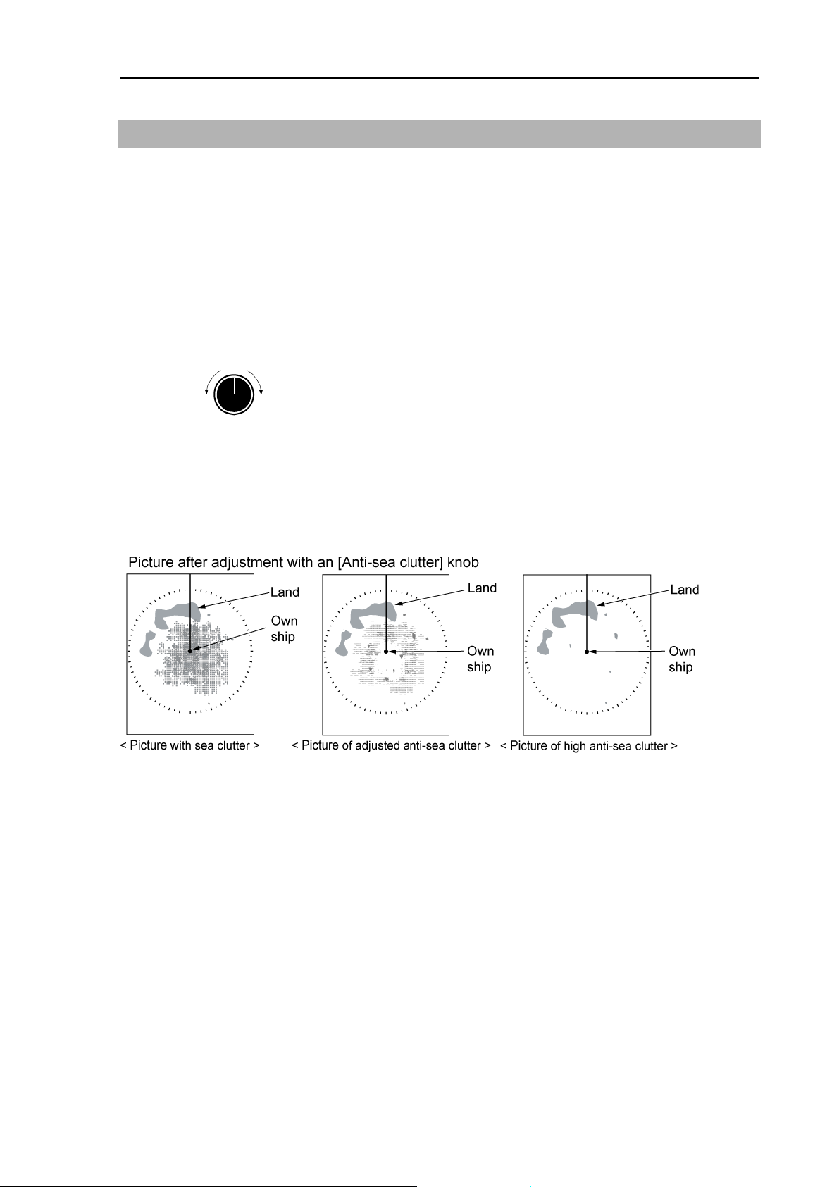
3.6 Reduce sea clutter (STC)
In short distance range, the echo from the sea clutter appears on the display even in calm state. In
rough seas, the echo from the sea clutter appears heavily around the center of the screen and the
targets become hard to be observed.
By using [SEA] knob, suppress this influence of anti-sea clutter and adjust it to make targets easier to
be observed.
1 Turn [SEA] knob clockwise to increase anti-sea clutter effect.
2 Turn [SEA] knob counter clockwise to decrease anti-sea clutter effect.
nti-sea clutter
Low
・ The knob shall be turned to leftmost position in a calm environment.
・ This function reduces gain in shorter ranges. Pay attention that the actual targets will be lost if the
knob turned clockwise too much.
High
0093125002-04 3-5
Page 30
Chapter 3 Basic operation MDC-2200/2500 Series
A
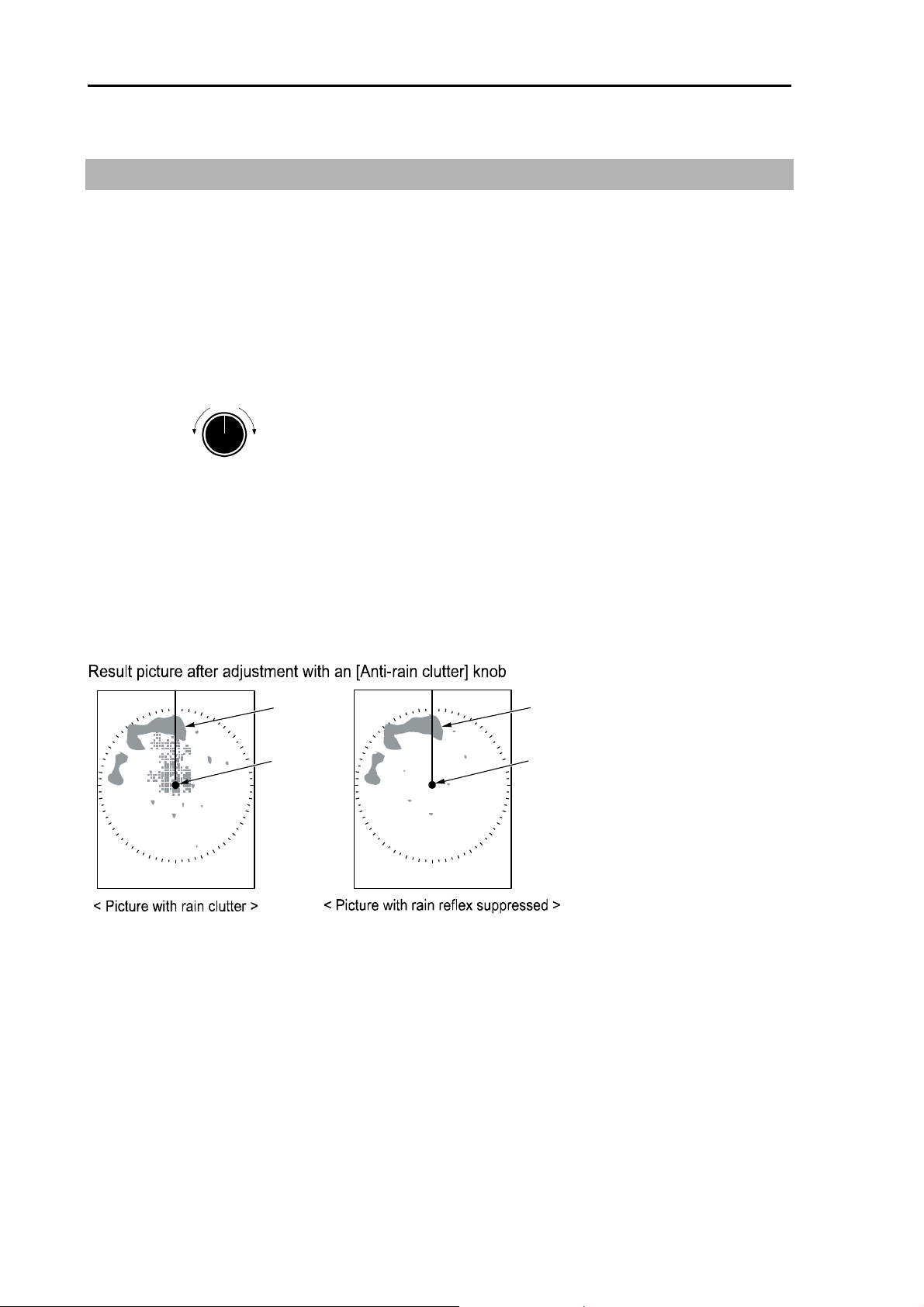
3.7 Reduce rain/snow clutter (FTC)
In rain or snow weather, targets become hard to be observed as a result of the echo from those
reflections.
By using [RAIN] knob, you can suppress influence from the unwanted reflection of rain and snow and
make the picture easier to be observed.
1 Turn [RAIN] knob clockwise to increase anti- rain clutter effect.
2 Turn [RAIN] knob counter clockwise to decrease anti- rain clutter effect.
nti-rain clutter
Weak
The knob should be turned to leftmost position in normal environment.
Turning the knob clockwise, profiles of targets which were hidden due to the echo of rain/snow etc.
appear but pay attention not to fail to miss the small targets.
When a function to suppress ant-rain and anti-snow clutter is adjusted too high, it may prevent from
detecting targets due to suppression of echo not only from rain and snow but also from the targets
Strong
land
Own
ship
Land
Own
ship
0093125002-04 3-6
Page 31

MDC-2200/2500 Series Chapter 3 Basic operation
3.8 Change transmission pulse length (SP/LP)
A function capable of achieving suitable target detection by changing the transmission pulse length is
provided.
The short pulse length [SP] is suitable for dense targets due to high resolution.
The long pulse length [LP] is suitable for detection of small targets due to high gain.
Pulse length can be changed in range of 0.75nm, 1.5nm, 3nm and 6nm. (factory setting)
1 Press [SP/LP] key. Two types of pulse length which are suitable in that range will be changed each
time by pressing key.
Current pulse length is shown upper left of the screen.
Range
レンジ
Pulse length
パルス幅
1.5
M1W
short long
SP < M1W < M1N < M2W < M2N < L1P < L2P
3.9 Enhance target (ENH)
This function is intended to enhance a desired target on the screen and make the image easier to be
observed.
1 Press [ENH] key. Each time by pressing, It switches over [ENH1] -> [ENH2] -> [ENH 3] -> [Off] .
Enhance levels are:
ENH 1: small
ENH 2: medium
ENH 3: large
Current selected enhance target mode is displayed on the upper right of the screen.
・ Target enhance function also magnifies the echo of sea and rain clutter.
Combine to use the function of [SEA] knob and [RAIN] knob to obtain the optimized picture.
ENH 1 ENH 2 ENH 3
0093125002-04 3-7
Page 32

Chapter 3 Basic operation MDC-2200/2500 Series
f
3.10 Measure distance and bearing of a target
Measure distance (VRM: Variable Range Marker)
The VRM is used to measure the distance of a target from the own ship’s position and the optional
position.
Two types, [VRM1] and [VRM2] are provided.
After selection of [VRM1] or [VRM2], Adjust [VRM] to the target by turning knob and then measure the
distance.
VRM can be shifted quickly when being operated by pressing the knob.
1 Press [VRM1] key to display a dotted line circle of [VRM1].
The distance to VRM1 is indicated on the lower right on the screen, and also a
displayed on the left side of the distance display.
VRM1
Own ship
Target
Radius changed by VRM knob
VRM1
8.990NM
Distance to Target
symbol is
2 The dotted line circle is aligned to the target to be measured its distance by turning [VRM] knob.
The value of distance display is the distance to the target.
Decreace of
range
Increace o
range
VRM knob
3 Press again the [VRM1] key to turn VRM1 off. The distance display in lower right of the screen is
turned off simultaneously.
4 Press [VRM2] key to display the broken line circle of VRM2. Operation procedure and distance
display are the same procedure as for [VRM1].
5 Both VRM1 and VRM2 can be displayed simultaneously by pressing [VRM1] key and thereafter
[VRM2] key.
6 Switching over of VRM1 and VRM2 are performed by pressing [VRM] key to be used.
(For MDC-2500 series. selected VRM key color changes to red.)
・ The unit of VRM distance can be selected from “NM, km, sm, and RANGE LINK.
To be set up as follows: Detail menu => “ MARKER” => “ VRM1 UNIT” or “ VRM2 UNIT”
Detail menu shall be referred to “Display detailed menu” (page 4-2)” for release protection.
Refer to “Measure distance and bearing between two points (Offset)” (page 3-13) in order to
offset the center point of VRM to the intended position (position of cross cursor).
0093125002-04 3-8
Page 33

MDC-2200/2500 Series Chapter 3 Basic operation
Measure bearing (EBL: Electronic Bearing Line)
This is used for measuring the bearing of the target from the own ship or from the optional point.
Two types of [EBL1] and [EBL2] are provided.
After selection of [EBL1] or [EBL2] by pressing either key, align electronic bearing line to the target by
turning the knob and then measure the bearing.
EBL can be shifted quickly when being operated by pressing the knob.
1 Pressing [EBL1] key, [EBL1] electronic bearing (dotted line) is displayed.
EBL1 bearing value on the lower left of the screen and a
EBL1
Target
Bearing cahnges
by turning EBL knob
Own ship
EBL1
060.5°
Target bearing from own ship
mark on its left are displayed.
2 By turning [EBL] knob, align the electronic bearing line to the target to be measured.
The value of bearing display is the bearing of the target.
ClockwiseCounter clockwise
EBL knob
3 Press [EBL1] key again to turn EBL1off.
4 Press [EBL2] key, and [EBL2] electronic bearing (broken line) will be displayed.
The operation procedure and display of the bearing is the same as for [EBL1].
EBL2
EBL2
060.5°
340.0°
EBL1
Own
ship
5 Press [EBL1] key then press [EBL2] key to display both EBL1 and EBL2.
6 Press [EBL] key to switch over either EBL1 or EBL2 to be used.
(In MDC-2500 series, selected EBL key color changes to vermillion.)
Refer to “Measure distance and bearing between two points” (page 3-13) in order to offset EBL
center point to the intended position (position of cross cursor).
0093125002-04 3-9
Page 34

Chapter 3 Basic operation MDC-2200/2500 Series
Measure distance/bearing (PI: Parallel index line)
This function is used to display a parallel straight line from own ship or optional location and measure
distance and bearing.
The number to be displayed of parallel index line is selectable from normal (number of the rings of the
range to be used), 1 to 7 lines.
Display single side (default) or both sides of screen can be switched over.
- Parallel index line can be shifted quickly when being operated by pressing the knob.
(For MDC-2200)
EBL2/VRM2 or Parallel index line is selectable to use in case for MDC-2200. It was set to EBL2/VRM2
in ex-factory.
Set up to Parallel index line from marker selection menu to use Parallel index cursor.
1 Setting of Parallel index cursor
Press [MENU] key to display “Menu”.
To proceed “MARKER” =>”MARKER SEL”, set up EBL2/VRM2 to the PI, then press [ENT] key.
MARKER
ECHO
NAV
ALARM
ATA/EPA
AIS*
CHART
DATADISP
STARTUP
* : Displayed at installation ofAIS unit (optional).
**:MARKER SEL is provided for MDC-2200 series onl
Move to
the right
RANGE RINGS
BRG TRUE/REL
MARKER SEL**
PARALLEL INDEX
CURSOR
Move to
the right
y.
EBL2/VRM2
PI
2 Display line number setting
Press [MENU] key to display “Menu”.
To proceed “MARKER” => “PARALLEL INDEX”, then select display number and press [ENT] key.
MARKER
ECHO
NAV
ALARM
ATA/EPA
AIS*
CHART
DATADISP
STARTUP
* : Displayed at installation of AIS unit (optional).
**:MARKER SEL is provided for MDC-2200 series onl
Move to
the right
RANGE RINGS
BRG TRUE/REL
MARKER SEL**
PARALLEL INDEX
CURSOR
Move to
the right
y.
NORMAL
1
2
3
4
5
6
7
In Normal, line number is equal to number of Range ring.
Designated number of PI is displayed when 1 – 7 value is selected.
3 PI is displayed by pressing [EBL2] or [VRM2].
4 Bearing is displayed middle lower left of the screen, and distance between PI line is displayed
middle lower right of the screen during PI display.
0093125002-04 3-10
Page 35

MDC-2200/2500 Series Chapter 3 Basic operation
V
5 The interval between lines can be varied by pressing and rotating [VRM2] knob.
In “Normal” setting, variable range is min: equal to Range ring one, max: 50% of selected range.
In “1 – 7” setting, min: 0, max: about 1.6 times of selected range.
Bearing can be varied by pressing and rotating [EBL2] knob.
ClockwiseCounter clockwise
PI
PI REL
EBL knob
Refer to “Measure distance and bearing between 2 points (Offset)” (page 3-13) for offsetting
center of Parallel index line to optional position (cross cursor position).
(For MDC-2500)
040.0° 3.000NM
1 Setting of number of lines to be displayed
Press [MENU] key to display “Menu”.
To proceed [MARKER] => [PARALLEL INDEX] and select number of lines then press [ENT]
key
MARKER
ECHO
NAV
ALARM
ATA/EPA
AIS*
CHART
DATADISP
STARTUP
* : Displayed at installation of AIS unit (optional).
**:MARKER SEL is provided for MDC-2200 series onl
Move to
the right
RANGE RINGS
BRG TRUE/REL
MARKER SEL**
PARALLEL INDEX
CURSOR
Move to
the right
y.
NORMAL
1
2
3
4
5
6
7
In Normal, line number is equal to Range ring one.
Designated number of PI is displayed when 1 – 7 value is selected.
2 PI is displayed by pressing [VRM2] knob.
Bearing is displayed by figure on middle lower left of the screen, and distance between PI lines
is displayed on middle lower right of the screen during PI display.
PI lamp in lower left of [VRM] knob is lighted during PI display.
RM knob
PI
PI REL
000.0°
Push
3.000NM
0093125002-04 3-11
Page 36

Chapter 3 Basic operation MDC-2200/2500 Series
e
2 The interval between lines can be varied by rotating [VRM] knob.
Though the distance may be changed freely, the setting of the interval of [VRM] can only be
changed in [NORMAL] mode for the basic number of lines.
Increase of distanc
Decrease of distance
Decrease of
distance
Increase of
ditance
VRM knob
PI
PI REL PI
000.0° 2.500NM
PI REL
000.0° 5.000NM
Rotate the [EBL] knob to change bearing.
ClockwiseCounter clockwise
PI
PI REL
EBL knob
040.0° 3.000NM
Refer to “Measure distance and bearing between two points (Offset)” (page 3-13) for offsetting
the center of PI to optional position (cross cursor position).
0093125002-04 3-12
Page 37

MDC-2200/2500 Series Chapter 3 Basic operation
Measure distance and bearing between two points (Offset)
・Though VRM, EBL or PI uses the own ship as an original point for default value, this original point
can be changed (offset) to the optional position. This enable to measure distance and bearing between
two targets.
・ The change of original point (offset) can be made for three types independently: VRM1 and EBL1,
VRM2 and EBL2 and for the PI.
1 By pressing [EBL] knob while [EBL1] and [VRM1] are selected, the original points of EBL1 and
VRM1 can be offset to the position of parallel index line.
Then, the numerical values of EBL and VRM displayed at lower part of the screen will change to
blue.
(For MDC-2500) The offset lamp color located at lower right under [EBL] knob will change to
vermillion.
EBL1
Target A
EBL knob
Target B
Own ship position
VRM1
Push
EBL1
331.5°
VRM1
1.424NM
By operating [Joystick], the markers of EBL1 and VRM1 will move together with cross cursor.
EBL1
Target A
Target B
Own ship position
Cursor
VRM1
Move
Joystick
EBL1
331.5°
VRM1
1.424NM
2 By moving the cross cursor, point to the target B to be measured.
3 By turning [EBL] knob and [VRM] knob, point it to the another target A.
4 The bearing and distance from target B to target A are indicated as EBL1 and VRM1.
EBL1
Target A
VRM1
Target B
Own ship position
EBL1
331.5°
VRM1
1.424NM
5 By pressing [EBL] knob after having confirmed above, the origin points of EBL1 and VRM1 will be
restored to the own ship position.
0093125002-04 3-13
Page 38

Chapter 3 Basic operation MDC-2200/2500 Series
6 For [EBL2] and [VRM2], the same procedure as that for [EBL1] and [VRM1] is taken to set up.
3.11 Change echo color (DAY/NIGHT)
This function is used to change echo colors on the screen depending on day and night navigation to
make viewing easier.
The image and background color can be set independently for daytime or for nighttime, for which the
echo color shall be registered beforehand.
(For MDC-2200)
1 Press [MENU] key to display “Menu”.
Select [ECHO] => [DAY/NIGHT] and select Day echo or Night echo color then press [ENT] key.
(For MDC-2500)
1 Press [DAY/NIGHT] key to switch over Echo color to Day echo and Night echo alternatively.
The above can be operated by using Menu.
3.12 Remove the heading line
This function is used when a target is overlapped with a heading line and hard to be observed.
1 Press [OFF] key to temporarily hide the heading line.
A target toward on the heading line becomes easier to observe while the key is kept being
pressed. (It is not possible to remove it continuously.)
There is a function to make heading line blinking without key operation. (Detailed menu=>
[MARKER] => [HL BLINK] => ON)
0093125002-04 3-14
Page 39

MDC-2200/2500 Series Chapter 3 Basic operation
3.13 Relocate own ship position (Off-centering)
This function is used to get broad outlook of heading line by relocating position of own ship.
1 Move a cross cursor to the position you want to move own ship by operating [Joystick].
2 Press [OFF CENT] key to move own ship to cross cursor position.
Own ship
Own ship
3 Press [OFF CENT] key again to return own ship to the center of the screen.
Off center area is limited to 66% of the designated range.
Own ship relocatable area
34%
66%
Own ship
Off center position can be fixed to stern orientation instead of cross cursor position.
(Chapter 4 4.3 ECHO menu => [OFF CENTER POSITION] => OPPOSITE)
0093125002-04 3-15
Page 40

Chapter 3 Basic operation MDC-2200/2500 Series
3.14 Select display mode
The display mode is combined with bearing display mode and target motion display mode.
The bearing display mode is provided with 3 types: [HUP], [CUP] and [NUP].
The target motion display mode is provided with 2 types: [RM] and [TM].
Following 5 display modes are provided for this device with combination of these modes described
above.
N UP
RM
RM
TM
RM
TM
RM and N UP RM display mode.
TM and N UP TM display mode.
H UP
C UP
C UP
N UP
・ Input bearing signal to use C UP
・ Input of both bearing and speed signal to use C UP
(For MDC-2200)
1 Press [MENU] key to display “Menu”.
Select [ECHO] => [DISP MODE] then select from H UP
Display mode is shown on the upper left of the screen.
(For MDC-2500)
, C UP RM, C UP TM, N UP RM, N UP TM.
RM
1 Press [MODE] key. The display mode will be changed in the following order each time you press
[MODE] key. Current display mode is displayed on the upper left of the screen.
For H UP (Head up mode)
Heading line bearing is always displayed to the direct top of the screen.
This mode is based on bow of the ship and is suitable to watch targets because the range of view is the
same as that at the time of ship handling.
Heading
N
Target 1
Own ship
Land
Target 2
0093125002-04 3-16
Page 41

MDC-2200/2500 Series Chapter 3 Basic operation
For C UP (Course up mode)
When “C UP RM” or “C UP TM” is selected, the heading line is set to the course and the setup course is
shown on direct top of the screen.
This mode is used for navigation along the setup course.
When heading is changed from the setup course after C UP setting, heading line is shown deviated
accordingly from the setup course.
To navigate along the setup course, ship handling shall be done to keep heading line displayed on
direct top of the screen.
N
Target 1
Own ship
Land
< [C UP] selected >
Heading
Target 2
N
Target 1
Own ship
Land
Specified course
Heading
Target 2
< Heading deviated from course >
For N UP (North up mode)
This mode always keeps displaying true north on the top of the screen. It makes easy to consult with
the chart because of the display oriented to a true north.
N
Target 1
Heading
Own ship
Target 2
Land
0093125002-04 3-17
Page 42

Chapter 3 Basic operation MDC-2200/2500 Series
For relative motion (RM) and true motion (TM)
Relative motion indicates the motion of surrounding targets with own ship’s position fixed at the center
of the screen.
Because own ship position is centralized, fixed targets such as the land also move on the display while
the ship is moving.
True motion indicates the motion of the target as a center of the specified bearing.
Fixed targets that do not move in any direction stay on the display as they were and actually moving
targets move on the screen.
*No true motion [TM] is available for [H UP] mode because the heading always continues to move.
Relative motion (RM): The own ship position is fixed and the other surrounding targets move on the
screen.
This is useful for monitoring the surrounding situation from the own ship’s
position as a center.
Own
ship
Fixed
Moving
Land
Moving
0093125002-04 3-18
Page 43

MDC-2200/2500 Series Chapter 3 Basic operation
True motion (TM): Own ship’s position moves according to its speed and its course on the screen.
Stationary targets are fixed on the screen, while moving targets move on the screen.
This mode is useful for monitoring your position from the fixed targets such as a
land etc.
Land
Own ship
Moving
Fixed
Own ship
Own ship position
34%
66%
relocatable area in TM
Center of display
Reset true motion
When own ship position reaches to about 66% of effective screen radius, own ship position is
automatically reset to opposite orientation of the screen.
N
Own ship
Moving toward
the stern
N
Own ship
・ It is also possible to reset own ship position before it reaches to 66% of effective screen radius.
1 Press [MENU] key to display “Menu”.
Select [ECHO] => [TM RESET] and then press [ENT] key.
0093125002-04 3-19
Page 44

Chapter 3 Basic operation MDC-2200/2500 Series
3.15 Use ATA/EPA
ATA (Automatic tracking aids) function provides to acquire up to 50 targets of ship manually (specifically
select target) or automatically (in prior setting area ) then to track automatically.
EPA (Electronic Plotting aids) function provides calculation of course and speed of the target based on
the information of 2 point position data manually acquired and the information acquired again after 30
seconds or later.
This device is equipped with ATA board as a standard. ATA function is automatically selected at the time
of shipment.
The tracking data of ATA/EPA can be displayed in data display area on the lower part of the screen.
There are following information necessary to avoid collision.
CPA (Closest Point of Approach Minimum approach point to the target (distance)
TCPA (Time to Closest Point of Approach) Time to Closest Point of Approach
Speed of the target
Course of the target
Vector of the target
・ Heading bearing and speed input by optional GPS compass or equivalent is required to input
to use ATA/EPA function.
・ Object acquired and started tracking is called “Target”.
Item ATA EPA
Manual acquisition Yes Yes
Auto acquisition Yes No
Tracking method Automatic Manual
Max. tracking number 50 50
(ATA operation method)
Manual acquisition
(For MDC-2500)
1 Move cross cursor using [Joystick] to lay on the target to be acquired, and then press [ACQ] key. A
symbol is displayed at location of the cursor.
“ ˮ mark is displayed immediate after acquisition then changes to ○ mark after about 30sec.
Target number is attached beside the mark.
(For MDC-2200)
1 Move cross cursor using [Joystick] to lay on the target to be acquired, and then press [F2] key
1
. A symbol is displayed at location of the cursor.
“ ˮ mark is displayed immediate after acquisition then changes to ○ mark after about 30 sec.
Target number is attached beside the mark.
(Note 1) In MDC-2200, [F2] key is assigned to “ACQ” at the factory setting. The setting can be made to
0093125002-04 3-20
Note
Page 45

MDC-2200/2500 Series Chapter 3 Basic operation
other Function key.
Delete target (Select and delete)
(For MDC-2500)
1 Move cross cursor using [Joystick] to lay on the target to be deleted and then press [ACQ] key by
pressing [OFF] key.
(For MDC-2200)
1 Move cross cursor using [Joystick] to lay on the target to be deleted and then press [F2] key by
pressing [OFF] key.
(Note 1) In MDC-2200, [F2] key is assigned to “ACQ” at the factory setting.
Delete all targets
This function is used to delete all acquired targets.
1 Press [MENU] key to display “Menu”.
Select [ATA/EPA] => [ALL DELETE], and then press [ENT] key.
MARKER
ECHO
NAV
ALARM
ATA/EPA
AIS*
CHART
DETADISP
STARTUP
* : Displayed at installation ofAIS unit (optional).
Move to
the right
ATA/EPA TYPE
ACQ
DELETE
ALL DELETE
MAN ACQ NO
AUTO DETECT
TARGET ID
TARGET SELECT
EPA UPDATE
DATA STYLE
Use Automatic acquisition (Up to 40 targets can be acquired in default)
1 Press [MENU] key to display “Menu”.
Select [ATA/EPA] => [AUTO DETECT], and then press [ENT] key.
MARKER
ECHO
NAV
ALARM
ATA/EPA
AIS*
CHART
DETADISP
STARTUP
Move to
the right
ATA/EPA TYPE
ACQ
DELETE
ALL DELETE
MAN ACQ NO
AUTO DETECT
TARGET ID
TARGET SELECT
EPA UPDATE
DATA STYLE
* : Displayed at installation of AIS unit (optional).
0093125002-04 3-21
Page 46

Chapter 3 Basic operation MDC-2200/2500 Series
2 ATA auto acquisition setting area is displayed on the screen.
Bearing
Width
Own ship
Depth
GZ
BRG 315.8°
WIDTH 100.3°
RNG 4.133NM
DEPTH 0.755NM
Range
- Setting items are [BRG], [RNG], [WDT] and [DPT].
- Value less than 5° for Bearing, 0.1NM for Depth is unavailable to set up.
- Use [VRM] knob and [EBL] knob for setting.
3 Press [EBL1] or [EBL2] key, and then change [BRG] <=> [WIDTH] by using [EBL] knob.
In the same way, Press [VRM1] or [VRM2] key, and then change [RNG] <=> [DPPTH] by using
[VRM] knob.
- In figure display on the lower left of the screen, Item under setup is indicated by left
mark.
4 Setup process is completed by pressing [ENT] key after the area designation, then auto
acquisition starts.
・ To switch auto acquisition off, display the same Menu then select Auto acquisition and press
[ENT] key.
・ To change auto acquisition area, off acquisition once, then restart from procedure 1. Setting
area is recorded.
0093125002-04 3-22
Page 47

MDC-2200/2500 Series Chapter 3 Basic operation
Detailed target data display method
Detailed target data can be displayed on the lower part of the screen.
1 Press [MENU] key to display “Menu”.
Select [DATADISP] => [DISP 1] / [DISP 2] / [DISP 3] then turn Joystick to right.
Select ATA/EPA then press [ENT].
Detailed data display area
DISP 1
DISP 2 DISP 3
2 Data display part background is set transparent in default.
Setup by following procedure to fill background to ease to see data.
Press [MENU] key to display “Menu”.
Select [DATADISP] => [LOWER DISP BACK] then set to [ON].
DISP 1
DISP 2 DISP 3
3 When 3 target data is displayed in the detail data display area. When need to switch to display for
more than 4 targets, lay cursor on target to display then press [ENT] key.
Selected target data will be displayed in left display part. Old data will be shifted to right and the old
data displayed to the right will disappear.
0093125002-04 3-23
DISP 1
latest data
DISP 2 DISP 3
Page 48

Chapter 3 Basic operation MDC-2200/2500 Series
Other setting
1 Setup vector length MENU => NAV => VECTOR
Setting value : OFF, 30sec, 1min, 3min, 6min, 12min, 30min, 60min.
・ This item is to set vector length.
・ Vector is a line that represents course and speed of tracking target. Orientation of the line denotes
course while length of the line denotes speed.
For example when designates 1 min, the leading edge of vector points predicts position after 1min.
2 Vector mode MENU => NAV => TRUE/REL
Setting value : Relative, True
・This item is to set vector display mode: Relative or True.
・ True motion displays course and speed of the target actually moving, while relative motion displays
relative course and speed of the target sawn from the own ship’s position.
In true vector mode, vector orientation is true course of target and length is proportional to its speed.
Own ship vector is also displayed in true vector mode.
Relative vector display does not show real motion of the target but show relative motion to the own
ship.
Target with its vector orientated to own ship is dangerous ship.
Accordingly, true vector is used for grasping actual situation of target while relative vector to grasp
CPA of target.
3 CPA (Closest point to approach) setting MENU => ALARM => LIM CPA
Setting value : 0.0 to 19.9NM
・This item is to set closest range from own ship.
4 TCPA (Time to Closest point of approach) setting MENU => ALARM =>LIM TCPA
Setting value : 1 to 63min
・ This item is to set time to the closest range from own ship.
When the a target becomes into setting value of both CPA and TCPA area, it is regarded as
dangerou
second and sounds alarm in every 0.5 second.
s target and change to symbol mark. In addition, this symbol mark blinks in every 1
△
Alarm can be stopped by pressing [OFF] key.
5 Manual acquisition setup MENU => ATA/EPA => MAN ACQ NO
Setting value : 0 to 50
・ This item is to designate manually acquiring target number out of total 50 targets.
・ Pay attention when manual acquisition number is set to 50, auto acquisition is not available to use.
0093125002-04 3-24
Page 49

MDC-2200/2500 Series Chapter 3 Basic operation
EPA operation method
1 Move the cross cursor with [Joystick] to lay on the desired target.
(For MDC-2500)
Press [ACQ] key on the upper right of the operating panel. The symbol of starting acquisition is
overlaid on the target.
(For MDC-2200)
Note1
Press [F2] key
(Note 1) In MDC-2200, [F2] key is assigned to “Acquisition” at the setting in factory.
Note : When acquiring 2 or more target (up to 50), select target number by using Menu then start
. The symbol of starting acquisition is overlaid on the target.
+ [ACQ] key
operation.
2 After 30second passed, lay cross hair cursor on moved target then press [ACQ] key ([F2] key for
MDC-2200) again.
Note : When acquiring 2 or more target (up to 50), select target number by using Menu then start
operation.
・The symbol moves to the latest target position and its course and speed are displayed by vector.
・ Up to 5 history track points are shown on the display with [・] symbol.
+ [ACQ] key
3 As the symbol moves according to the latest vector data, periodic use of procedure 2 above,
allows the symbol to keep tracking the target which changes its speed and heading.
・ If no additional manual tracking is done within 10 min and over, the EPA reliability is judged to have
been lost and the symbol stops tracking.
・ If no additional manual tracking is performed within 15 min and over , tracking is deleted
automatically.
0093125002-04 3-25
Page 50

Chapter 3 Basic operation MDC-2200/2500 Series
W
Update EPA
This function is used to correct the latest tracking point.
1 Move a cursor to the point to be corrected by using [Joystick].
rong position
2 Press [MENU] key to display “Menu”.
Select [ATA/EPA] => [EPA UPDATE], and then press [ENT] key.
MARKER
ECHO
NAV
ALARM
ATA/EPA
AIS*
CHART
DETADISP
STARTUP
Move to
the right
ATA/EPA TYPE
ACQ
DELETE
ALL DELETE
MAN ACQ NO
AUTO DETECT
TARGET ID
TARGET SELECT
EPA UPDATE
DATA STYLE
* : Displayed at installation ofAIS unit (optional).
3 Update tracking setup.
0093125002-04 3-26
Page 51

MDC-2200/2500 Series Chapter 3 Basic operation
Types and meaning of ATA/EPA symbol
The following symbols are overlapped on ATA acquisition target.
Normal symbol
Alarm symbol
Blink in
0.5 sec. interval
Blink in
0.5 sec. interval
Meaning
Displayed on acquisition setup.
Displayed in steady tracking state.
Displayed at indicating numerical value after
steady tracking
Meaning
Displayed when above steady tracking symbol has
under run both specified CPA and TCPA value.
Displayed when above indicating numerical value
symbol has under run both specified CAP and TCPA.
Displayed when the tracked target is out of tracking,
and then the alarm sounds.
Both display and sound disappear in 15 sec.
Displayed when it entries the guard zone.
The dispaly disappears after it exits guard zone.
0093125002-04 3-27
Page 52

Chapter 3 Basic operation MDC-2200/2500 Series
3.16 Use F (Function key)
This device is provided with F (Function).
Function key can be operated easily when assigned functions to the function key.
It has following keys in the function keys.
For MDC-2200 F1, F2, ”SEA” “RAIN” and “Gain”
For MDC-2500 F1, F2, F3 , ”SEA” “RAIN” and “Gain”
( Key functions of “SEA” “RAIN” and “Gain” are available by pressing each knob) ,
Assignment method of function key
1 Press [MENU] key to display “Menu”.
Select [STARTUP] => [F1 KEY SET], and then press [ENT] key after selecting assignment item.
RANGE RINGS
BRG TRUE/REL
DAY/NIGHT
MODE
TRAILS
IR
TUNE SELECT
MARKER
ECHO
NAV
ALARM
ATA/EPA
AIS*
CHART
DETADISP
STARTUP
* : Displayed at installation of AIS unit (optional).
Move to
the right
TUNE AUTO
TUNE MANUAL
BRG ADJ
TX DELAY ADJ
STC CURVE1
MBS
F1 KEY SET
F2 KEY SET
F3 KEY SET
RAIN KEY SET
SEA KEY SET
GAIN KEY SET
Move to
the right
PROCESS
ZOOM
TM RESET
HOLD
VECT TRUE/REL
ALARM1
GUARD ZONE
ACQ
DELETE
ALL DELETE
TARGET
UPDATE
CHART
MARK OWN
MARK CURSOR
TLL OUT
UPPER DISP
VIDEO MODE
SHORT CUT
OFF
2 The same procedure as step 1 is applied for [F2 KEY SET], [F3 KEY SET], [RAIN KEY SET], [SEA
KEY SET] and [GAIN KEY SET] by selecting each item and pressing the [ENT] key.
For short cut menu
“ Short cut menu” of arbitrary menu screen which has no assignment item to the function key can be
set up. The set up screen menu can be displayed immediately by pressing function key.
The operation becomes easy if sub-menu in the detailed menu is set up.
Setting method of short cut
1 Select short cut menu by using function key (for example [F1] key).
2 Display arbitrary menu to be set by operating menu..
3 Press [OFF] key + [F1] key.
4 The setup is complete when beeping the buzzer for about 2 seconds.
5 Press [F1] key under the state of menu being deleted. Then the assigned short cut menu will be
displayed immediately.
0093125002-04 3-28
Page 53

MDC-2200/2500 Series Chapter 3 Basic operation
Position data output
Function key provides the function to output latitude & longitude information of arbitrary position on
the radar screen. This position information is displayed as the mark on the plotter screen by
connecting to the plotter device.
This information is output as TLL sentence.
Following 2 methods are available for the operation of latitude & longitude output.
Output latitude & longitude information of cross cursor position.
1 Select Detailed Menu => [I/O] => [ OUTPUT(J4,J5)] => [TLL OUT] => [TARGET]
2 Set up [TLL OUT] to a Function key.
3 Move cross cursor to the position to output information, then press [TLL OUT] of function key.
The data of cross cursor position will be output, each time one presses function key.
Refer to “Display detailed Menu” (Page 4-2) for Detailed Menu operation.
Input mark into own ship position or cross cursor position and output latitude & longitude
information.
1 Select Detailed Menu => [I/O] => [OUTPUT(J4, J5)] => [TLL OUT] => [MARK].
2 Assign [MARK OWN] or [MARK CURSOR] to Function key. 2 Function keys can be assigned as
[MARK OWN] and [MARK CURSOR] respectively.
3 Mark is input into own ship position and own ship position data is also output by pressing [MARK
OWN] function key.
Mark is input into cross cursor position and the data of cross cursor position data is output by
pressing [MARK CURSOR] function key.
Refer to “Display detailed Menu” (Page 4-2) for Detailed Menu operation.
0093125002-04 3-29
Page 54

MDC-2200/2500 Series Chapter 4 Menu operations
Chapter 4 Menu operations
4.1 How to see and use Menu
Display menu (main menu)
Press [MENU] key then Main menu is displayed on the lower left of the screen.
MARKER
ECHO
NAV
ALARM
ATA/EPA
AIS
CHART
DATADISP
STARTUP
Delete menu
Menu is disappeared by pressing [MENU] key when “Menu” is displayed.
Select menu item
1 Select Main menu item by turning [Joystick] up or down after Main menu is displayed. (Selected
item is displayed in reverse)
2 Sub menu is displayed by turning [Joystick] to the right after Main menu item is selected.
3 Turn [Joystick] up or down to select sub-menu item.
4 Turn [Joystick] to the right after sub-menu is selected, then next sub-menu will be displayed.
5 Turn [Joystick] to the left to return previous menu.
< Menu operating procedure >
MARKER
ECHO
NAV
ALARM
ATA/EPA
AIS*
CHART
DATADISP
STARTUP
* : Displayed at installation ofAIS unit (optional).
**:MARKER SEL is provided for MDC-2200 series onl
Move to
the right
RANGE RINGS
BRG TRUE/REL
MARKER SEL**
PARALLEL INDEX
CURSOR
Move to
the right
y.
OFF
ON
Press [ENT] key.
0093125002-05 4-1
Page 55

Chapter 4 Menu operations MDC-2200/2500 Series
Determine setting
Select item in sub-menu and designate numerical value or select item and then press [ENT] key.
IMPORTANT: Designated value is not altered when Menu is closed without pressing [ENT] key.
Display detailed menu
As this device supports much functions, menu configuration is constructed in 2 levels (main menu and
detailed menu). Main menu is displayed in normal operation. (Basic menu operation is available in this
menu.)
Detailed menu is displayed by following operation.
1 Press [MENU] key to display “Main menu”. Select “DATADISP” => “PROTECT CANCEL” and then
press [ENT] key.
MARKER
ECHO
NAV
ALARM
ATA/EPA
AIS*
CHART
DETADISP
STARTUP
Move to
the right
UPPER DISP
LOWER DISP BACK
DISP 1
DISP 2
DISP 3
PROTECT CANCEL
* : Displayed at installation of AIS unit (optional).
2 Press [MENU] key again. Then, detailed “Menu” below will be displayed.
MARKER
ECHO
NAV
ALARM
ATA/EPA
AIS
CHART
DATADISP
STARTUP
I/O
SYSTEM
PRESET
CONTRAST
BITE
ANTENNA
OPTION
INITIAL
Refer to Installation manual
・Refer to the last section of this chapter for detailed Menu list.
0093125002-05 4-2
Page 56

MDC-2200/2500 Series Chapter 4 Menu operations
4.2 MARKER menu
Following designation items are provided in Marker menu.
Shaded item are displayed in detailed menu.
(1)
RANGE RINGS
(2)
BRG TRUE/REL
(3)
MARKER SEL
(4)
PARALELL INDEX
(5)
PI DISPLAY SIDE
(6)
CURSOR
(7)
VRM1 UNIT
(8)
VRM2 UNIT
(9)
PI UNIT
(10)
STERN MRK
(11)
CURSOR SHAPE
(12)
TRACKING CURSOR
(13)
HU MOVE
(14)
VRM/EBL CROSS
(15)
SCALE
(16)
(17)
(18)
(19)
(20)
(21)
(22)
(23)
CHARA
CHARA POSI
CHARA TYPE
HL BRINK
GUARD LINE
OS OUTLINE
OS PROFILE
SHIP’S PROFILE
OFF / ON
REL / TRUE
EBL2/VRM2 / PI
NORMAL / 1 - 7
ONE / BOTH
OFF / ON / L/L
NM / km / sm / RANGE LINK
NM / km / sm / RANGE LINK
NM / km / sm / RANGE LINK
OFF / ON
Select cursor shape
OFF / ON
OFF / ON
OFF / ON
OFF / ON
OFF / ON
IN / OUT
NUMERIC / SYMBOL
OFF / ON
OFF / ON, designate line width
OFF/ON
SET PROFILE
OFF / ON, SET SHIP’S PROFILE
(1) Display Range rings
Range rings is the marker to display fixed distance from own ship position.
It is used to measure range to the target.
Range
Ring separation
0093125002-05 4-3
6
1NM
Rang rings
Range 6NM
Ring separation 1NM
Page 57

Chapter 4 Menu operations MDC-2200/2500 Series
(2) Set bearing mode (relative/true mode)
Bearing display mode of [EBL]. [PI], [BRG SCALE] and [CROSS CURSOR] can be set at either relative
or true mode.
Relative bearing mode defines heading line at 0 degree while true bearing mode defines true north at 0
degree to display bearing of EBL, PI, BRG SCALE and CROSS CURSOR.
IMPORTANT: Heading signal shall be input by using GPS compass etc. to display with true bearing
mode.
IMPORTANT: True bearing mode is switched to relative bearing mode when heading signal is
intermitted.
(3) Marker selection (MDC-2200 only)
Switch over operation mode of EBL2/VRM2 key.
“EBL2/VRM2” or “Parallel index” can be selected.
Refer to “Measure distance/bearing (PI: Parallel index line)” (Page 3-10).
Parallel index is activated by pressing EBL knob for MDC-2500.
(4) Designate display lines of Parallel index.
Designate display lines of Parallel index.
Refer to “Measure distance/bearing (PI: Parallel index line)” (Page 3-10).
(5) Designate display direction of Parallel index
Parallel index can be displayed in one or both side based on the view from own ship.
PI
PI REL PI
000.0° 2.500NM
ONE BOTH
PI REL
000.0° 5.000NM
0093125002-05 4-4
Page 58

MDC-2200/2500 Series Chapter 4 Menu operations
(6) Designate cross cursor display method.
Information of cross cursor (bearing and range from own ship position) is displayed on the lower right of
the screen.
This information includes bearing and range from own ship position and latitude/longitude of cursor
position.
(Display latitude/longitude of cursor position)
Select [MARKER] => [CURSOR] => [L/L], then press [ENT].
Select setting item [ON] then press [ENT] key to stop latitude/longitude display.
IMPORTANT: Heading signal and latitude/longitude signal shall be input to display latitude/longitude.
・ Cursor display is turned off normally and when operated only with joystick, cursor can also be
displayed.
(Display only when cursor is in use)
Select [MARKER] => [CURSOR] => [OFF], then press [ENT] key.
Select setting item [ON], then press [ENT] key to keep cursor displayed.
Cursor
CURSOR
0.22.0°
9.059NM
139°88.255N
Latitude/Longitude
038°44.521E
< Display content of setting item >
OFF : Cursor is displayed only when joystick is operated.
ON : Cursor is always displayed.
L/L : Display bearing/distance from own ship position and latitude/longitude.
0093125002-05 4-5
Page 59

Chapter 4 Menu operations MDC-2200/2500 Series
(7) VRM1 Setting of range unit
VRM1 range unit can be changed. (NM, km, sm, RANGE LINK)
By setting RANGE LINK, the same unit as the display range of radar image is set.
(8) VRM2 Setting of range unit
VRM2 range unit can be changed. (NM, km, sm, RANGE LINK)
By setting RANGE LINK, the same unit as the display range of radar image is set.
(9) PI Setting of range unit
PI range unit can be changed. (NM, km, sm, RANGE LINK)
By setting RANGE LINK, the same unit as the display range of radar image is set.
(10) Display stern marker
This function is to display marker in opposite side of heading line (stern direction).
(11) Setting of cursor shape
Cross cursor shape can be changed as desired. Select out of 22 types of shape.
Lowest [+] is hair line cursor ,which can be displayed up to extreme top, bottom, right and left of the
screen.
Hair line cursor
(12) Tracking cursor
Tracking cursor is the function to have position of cross cursor moved onto the target nearest to
intersection of EBL1 and VRM1, interlocking with the movement of EBL1 and VRM1. Acquisition
operation of ATA/EPA can be performed without using joystick.
This function is effective when joystick operation is difficult under violent sea weather.
0093125002-05 4-6
Page 60

MDC-2200/2500 Series Chapter 4 Menu operations
(13) HU bearing interlocking
Cross cursor position is changed interlocking with own ship bearing change in H UP display mode.
It eases ATA/EPA target acquisition, AIS target selection and mark select operation even when bearing
is being changed.
(14) Display VRM/EBL intersection
Display mark on the intersection of EBL and VRM when both are displayed simultaneously. It is a
effective function to use when measuring range and bearing of the target.
Round mark is displayed on the intersection of EBL1 and VRM1, and also on the intersection of EBL2
and VRM2.
When both EBL1 and EBL2 are displayed at the same time, the following symbol will be displayed.
● mark at selected intersection;
○ mark for unselected intersection.
(15) Display bearing scale
Display bearing scale on the outer circumference of effective radar screen.
● mark is displayed intersection of heading line and bearing scale.
Heading line
Bearing scale
(16) Display bearing in numerical value or with symbol on the bearing scale
Display bearing numerically (000 to 350: 10 degree interval) or symbolically (N, NE, E, SE, S, SW, W,
NW).
When item (2) bearing mode is relative, heading bearing is “000” or “N”.
When item (2) bearing mode is true, true north bearing is “000” or “N”.
Refer to “item (18) Select display format”.
(17) Select bearing display location
Select bearing numerical or symbolical location on bearing scale.
Select display location either inner or outer of the bearing scale.
0093125002-05 4-7
Page 61

Chapter 4 Menu operations MDC-2200/2500 Series
(18) Select display format
This function is to select format (numeric or symbol) to show bearing on bearing scale.
Refer to “item (16) Display bearing”.
(19) Use blinking of heading line
This function is to blink heading line (and stern line) per each antenna rotation.
It is effective to observe small target on the heading line.
(20) Display guard line
This function is to display parallel lines to the heading on both side of own ship position.
Distance to guard line from own ship can be set at 0 to 10000m (left and right side independently).
(21) Display own ship’s outline
Set up On/Off of own ship’s outline display.
(22) Setup own ship’s profile (Cannot use on transmitting)
Press [MENU] key to display “Menu”.
Select [MARKER] => [OS PROFILE] =>
Specify the each numerical value based on the antenna position.
ANT position
*The center of echo image (PPI) is ANT.
・
OUTLINE
0093125002-05 4-8
Page 62

MDC-2200/2500 Series Chapter 4 Menu operations
(23) Display/generate own ship’s profile
This function is to generate own ship’s profile and to display on the screen.
Generate and input own ship’s profile by using up to 50 lines.
Display own ship’s profile: ON, OFF
Profile setting: X1 : -1000 to 1000m
Y1 : -1000 to 1000m
X2 : -1000 to 1000m
Y2 : -1000 to 1000m
Each line is designated by Start and End point based on antenna position.
(Example)
5m
10m
-1m
-1m
1m
Start
End
1
2
5
3
X1 Y1 X2 Y2
1 -1 -1 -1 10
2 -1 10 1 15
3 1 15 3 10
4 3 10 3 -1
4
5 3 -1 -1 -1
6 0 0 0 0
・ ・ ・ ・ ・
50 0 0 0 0
X1・Y1 denotes start point.
X2・Y2 denotes end point.
0093125002-05 4-9
Page 63

Chapter 4 Menu operations MDC-2200/2500 Series
4.3 ECHO menu
Following setting items are provided for Echo menu.
Shaded item is displayed in detailed menu.
(1)
MODE
(2)
TRAILS*
(3)
(4)
(5)
(6)
(7)
(8)
(9)
(10)
(11)
(12)
(13)
(14)
(15)
(16)
(17)
(18)
(19)
(20)
(21)
(22)
(23)
(24)
(25)
(26)
(27)
MODE
COLOR
SHAPE
RANGE KEEP
TIME KEEP*
TRUE MOVE
REL MODE
DETECT LVL
IR
PROCESS
DAY/NIGHT
ECHO COLOR D
ECHO COLOR N
BACK COLOR D
BACK COLOR N
ZOOM
TM RESET
TM RESET POSI
HOLD
SECTOR
RANGE UNIT
ROTATION MARGIN
ROTATION SPEED
ALL PPI
OFF CENT POSI
H UP
OFF / CONTINUE / 30SEC / 1MIN / 3MIN / 6MIN / 12MIN / 24MIN / 48MIN
TRUE / REL
BLUE / RED
OFF / ON
OFF / ON
COURSE / POSITION
HDG / TRUE
1 - 6
OFF / 1 / 2 / 3 / 4 / 5
OFF / 1 / 2 / 3
DAY / NIGHT
WHITE / YELLOW / GREEN / MULTI
WHITE / YELLOW / GREEN / MULTI
Action
Action
OPPOSITE / COURSE / CENTER
OFF / 1 / 2 START ANGLE, END ANGLE
NM / km / sm
0 - 30°
1 - 50
OFF / ON
CURSOR / OPPOSITE
/ C UP
RM
/ C UP
RM
/ N UP RM / N UP
TM
TM
* When TIME KEEP is ON, selectable time of TRAILS menu are:
OFF, CONTINUE, 30s, 1min, 3min, 6min, 12min, 24min, 48min,
1hr, 2hr, 4hr, 8hr, 16hr, 24hr
0093125002-05 4-10
Page 64

MDC-2200/2500 Series Chapter 4 Menu operations
(1)Select display mode
Display mode is expressed in combination of bearing display mode and motion display mode.
3 types mode [HUP], [CUP], [NUP] for bearing mode.
2 types mode [RM], [TM] for motion mode.
This device support following 5 types of mode in combination of above modes.
H UP
C UP
C UP
N UP
N UP
・ Heading signal input is required to use C UP
・ Both heading and speed signal input is required to use C UP
RM
RM
TM
RM
TM
and N UP RM mode.
RM
and N UP TM mode.
TM
1 Press [MENU] key to display menu.
Select ECHO => MODE then select from H UP
Display mode is displayed on upper left of the screen.
This operation can be performed by pressing [MODE] key on the panel for MDC-2500.
Refer to “3.14 Select display mode”.
, C UP RM, C UP TM, N UP RM、N UP TM.
RM
(2) Display trail
Display trail to get movement of the target.
Length of trail display is selected from CONTINUOUS, 30SEC, 1MIN, 3MIN, 6MIN, 12MIN, 24MIN and
48MIN.
No trail will be displayed when OFF is selected.
(3) Select trail display mode (relative or true)
2 types of trails display mode, relative (R) and true (T) are available.
Relative trail (R)
Target trail is displayed with the result of the course and speed of the target being added those of own
ship.
As the result, when own ship is seen overlapped on the trail extension, it means there is a risk of
collision in future.
Therefore, It is effective to determine instinctively a dangerous ship.
0093125002-05 4-11
Page 65

Chapter 4 Menu operations MDC-2200/2500 Series
< Display mode[N UP RM(R)] >
N
Two ships on a
collision course
Other
ship 1
Own
ship
Other ship 2
Other
ship 1
Own
ship
N
Other ship 2
Ships relative trailsCourse and speed of a real ship
Other ship 1 with its trail overlapped with EBL is a dangerous ship while other ship 2 is not.
Trail time is 6 min and trail length is equal to distance between own ship and other ship 1, it means that
they will collide after 6 min.
< Display mode[N UP RM(R)] >
Other
ship 1
Own
ship
N
6min
6min
Prospect of collision after 6 min.
True trail (T)
Display trail of moving target with its course and speed independently from own ship’s movement.
It is used to monitor course and speed of the target.
Fixed target such as land etc. is not displayed.
Trails of moving objects, own ship, other ship 1, other ship 2 are displayed respectively in the trails
moved according to each speed.
Land is not displayed as it doesn’t move.
0093125002-05 4-12
Page 66

MDC-2200/2500 Series Chapter 4 Menu operations
<Disp mode
N
Other ship1
Own
Land
「N U P
Current course and speed
RM(T)
」>
N
Other ship1
Other ship2
Own
Time passed
Land
Trail after time
(4) Select trail color (Blue or Red)
Select trail color from blue or red.
(5) Select trail display shape
Trail display shape can be selected from following 3 types.
Other ship2
Display trail same as target size
Display trail with thin line
Display trail with taper shape as the time passed
(6) Sustain range
This function is to use to display trail of previous range.
Initial setting is ‘Off” and past trail is deleted after display range is changed.
IMPORTANT: When sustain range function is “On” and pulse width is changed (long pulse width =>
short pulse width), screen may become hard to observe because of enlarged trail.
(7) Time keep
Factory default setting is “OFF”, and trails in the past are deleted when trail time is changed.
In case of “ON”, if either trail function is set “ON” or trail time is changed, the trail equivalent to the time
set is displayed. Movement of the other vessels (traveling direction and speed) can be captured
instantly.
In case Time keep function is set “ON”, the Alarm2 detection function cannot be used in the alarm menu.
Also, selectable time of TRAILS menu are OFF, CONTINUE, 30s to 24hr.
(8) Switching of base input sensor in true motion (Course or Position)
Switch calculation base of own ship movement in true trail display mode.
“Course” calculates movement distance from course and ship speed.
0093125002-05 4-13
Page 67

Chapter 4 Menu operations MDC-2200/2500 Series
“Position” calculates movement distance from course and latitude/longitude.
“Position” selection is effective to obtain stable trail under rough current where error of speed sensor is
large,
(9) Rel mode (Relative bearing criteria)
This is to select the signal (ship’s bearing or true) as criteria to record trails, in case trail mode is used
as “REL”.
Ship’ bearing: Trails are recorded taking the ship’s bearing as criteria.
The echo moving by own ship’s turn remains as trail.
True : This is active when such a bearing sensor as gyro, GPS compass is connected,
to record trails based on the true bearing from the bearing sensor.
The echo moving by own ship’s turn is not recorded as trail. When compared with
the ship’s bearing criteria, trail image is clearer and it is easier to see the relative position
with the other vessel.
(10) Trail detection level (1 to 6)
Designate trail display image strength selecting from value 1 to 6.
1 display trail even from weak image signal.
6 display trail only from strong image signal.
IMPORTANT: Lower detection level may display trail only in the position where target is not shown on
the screen.
(11) Interference rejection (IR)
Other ship’s radar of the same frequency band may cause interference noise on the screen. This
interference effect is not uniform but in most cases spiral or radius shape. This device provides
interference removal function to reduce these effects.
• Designate value is [Off, 1, 2, 3, 4, 5] and large value is for stronger removal effect.
• Too strong interference removal may mask small target.
(12) Display target stable using signal processing.
Observation of target in wave or target in long distance can be displayed stable by using signal
processing.
3 types of setting are provided for signal processing.
PROCESS 1 Residual mode (weak) Display stably the target appearing/disappearing on the screen.
PROCESS 2 Residual mode (strong) Same as above but effective for long distance target.
PROCESS 3 Correlation mode Suppress sea reflection and highlight target.
Note: Gain, Anti-sea, Anti-rain adjustment can not be reflected immediately during signal processing in
use.
0093125002-05 4-14
Page 68

MDC-2200/2500 Series Chapter 4 Menu operations
(13) Switch over Day/Night mode (Display MDC-2200 only)
Switch to pre-defined Daytime mode or Night mode display color.
Refer to “3.11 Change echo color”.
Switch by [DAY/NIGHT] key in the operation panel for MDC-2500 series.
(14) Daytime Echo color selection (Change Daytime mode color)
Select Daytime mode image color.
Select from “White”, “Yellow”, “Green” or “Multi”.
(15) Night Echo color selection (Change Night mode color)
Select Night mode image color.
Select from “White”, “Yellow” “Green” or “Multi”.
(16) Daytime background color selection (Change Daytime mode background
color)
Select Daytime mode background color.
(17) Night background color selection(Change Night mode background color)
Select Night mode background color.
(18) Enlarge cursor position image by zooming function
Zoom function enlarge image centered by cursor position in one step lower range.
It is used to observe surrounding situation of the target at cursor position in detail.
1
Move cursor to the enlarged image position by operating cursor with [Joystick].
2 Press [MENU] key to display “Menu”.
[ECHO] => [ZOOM], then press [ENT] key.
MARKER
ECHO
NAV
ALARM
ATA/EPA
AIS*
CHART
DETADISP
STARTUP
* : Displayed at installation of AIS unit (optional).
**:DAY/NIGHT is provided for MDC-2200 series onl
Move to
the right
MODE
TRAILS
MODE
SHAPE
IR
PROCESS
DAY/NIGHT**
ECHO COLOR D
ECHO COLOR N
ZOOM
TM RESET
y.
(19) Reset true motion
Reset own ship position to initial value when display mode is N UP TM or C UP TM
0093125002-05 4-15
Page 69

Chapter 4 Menu operations MDC-2200/2500 Series
Initial value is in the position set by “item (18) True motion reset position”.
(20) True motion reset position
Designate reset position when display mode is N UP TM or C UP TM.
Select from OPPOSITE, COURSE, CENTER.
(21) Fixed Image
When select “HOLD” menu then press [ENT] key, current image will be displayed as it is for 30 seconds.
It is used to determine target in detail.
“HOLD” is displayed on the upper part of screen during the image being fixed. It turns to preparation
screen after having passed 30 second.
IMPORTANT: Fixed image screen does not reflect latest circumstance. Pay attention to confirm
surrounding safety when used during navigation.
(22) Sector scan
Sector scan is the function not to display designated direction image on the screen. Set bearing
designation by “start bearing” and “end bearing” of sector.
Sector scan 1 is the mode not to display image of designated bearing (not suppress transmission) to
avoid reflection image such as from mast or other construction objects on the screen.
Sector scan 2 is the mode to stop transmission of the designated bearing and not to display image. It is
used to avoid transmission of radar wave to specific bearing.
(23) Designate range unit (NM, km, sm)
Change range unit of radar display.
This change also changes cross cursor range unit.
(24) Designate rotation angle
Image is rotated according to bearing change in H UP display mode. When rotation angle is set, the
image will be rotated when the bearing changes exceeding predetermined angle. Heading display
position changes according to bearing change within predetermined angle.
Setting rage is up to 30 degree.
(25) Designate rotation speed
Image is rotated according to bearing change in H UP display mode.
“Rotation speed” can change image rotation speed.
Initial value is 50 in maximum speed.
Image rotates slowly when setting value is lowered.
0093125002-05 4-16
Page 70

MDC-2200/2500 Series Chapter 4 Menu operations
(26) Full screen display
When full screen display turned off, the display range of radar image will remain within effective radius
only. It is used to ease to see surrounding values such as numeral data around screen.
(27) Off center position
Moving location of own ship position by operating “off center” can be set toward a cross cursor position
(default) or a stern direction.
0093125002-05 4-17
Page 71

Chapter 4 Menu operations MDC-2200/2500 Series
4.4 NAV menu
Following items are provided in Navigation menu.
Shaded display is displayed in detailed menu
(1)
(10)
STAB
(2)
MAN SET
(3)
MAN DRIFT
(4)
VECTOR
(5)
(6)
(7)
(8)
(9)
TRUE/REL
NAVLINE
BLOCK NO
BLOCK CLEAR
DETECT
SETUP
SEA / GND
0 - 359.9°
0 – 100kn
OFF / 30SEC / 1MIN / 3MIN / 6MIN / 12MIN / 30MIN / 60MIN
REL / TRUE
OFF / ON
1 - 20
CANCEL / CLEAR
OFF / ON
A1 - A25, B1 - B25
(1) Select stabilization base (SEA/GND)
“Stabilization on SEA” means display radar image mode based on sea surface using course
information from gyro (or equivalent) and speed information from speed from water sensor.
“Stabilization on GND” means display radar image mode based on ground using course and speed
information from satellite navigation system. Speed in water sensor may be affected by current and
stable operation may be spoiled. In this case, compensation against tide bearing and speed shall be
manually applied.
Stabilization base is calculation base for true motion (TM) of radar image and ATA/AIS target bearing
and speed.
(2) Set up tide bearing
Compensate effect of tidal bearing when speed over water sensor is used for “stabilization on GND”.
(3) Set up tide speed
Compensate effect of tidal speed when speed over water sensor is used for “stabilization on GND”.
(4) Set up vector display time
Set up vector display time for ATA, EPA, AIS and own ship course.
Direction of vector line denotes course and length denotes speed.
This vector means targets acquired by ATA, EPA, AIS or own ship will be reach to the location of
leading edge of vector after designated time has passed.
0093125002-05 4-18
Page 72

MDC-2200/2500 Series Chapter 4 Menu operations
(5) Set up vector display mode
Vector can be display by relative or true mode.
Relative mode displays target bearing and speed based on motion with respect to own ship.
True mode displays bearing and speed of the target actually moving.
Own ship vector line is not displayed in relative mode.
(6) Use navline
Navline function enables to attract attention for safety navigation with alarm display and sound when
own ship crosses the course preliminarily set (by latitude/longitude input).
Navline consists of 1 block 50 points (A1 to A25, B1 to B25) and can be saved up to 20 blocks.
Select arbitrary 1 block in use. Plural blocks can not be used simultaneously.
Navline can be used as simple drawing function by its alarm function being turned off (refer to item (9)
“detection”) and being line display only.
(7) Select block no. of navline
Select block no. of navline to be used.
1 to 20
(8) Delete navline by designating block no.
Delete navline data registered by latitude/longitude.
Select block no. to be deleted by using “block no.” menu.
Move cursor from “BLOCK CLEAR” => “CLEAR”, then press [ENT] key.
(9) Set up detection function
Set up function to display alarm indication and to sound alarm when own ship crossed the navline
during the navline being displayed.
IMPORTANT: No alarm is displayed when this setting is tuned “OFF”.
(10) Input/edit navline data
Designate block number beforehand and then input data on latitude/longitude input screen.
LAT LON
A1 _°__.___N _°__.___E
A2
A3
0093125002-05 4-19
SETUP : 1
LAT
LON
CLEAR
Page 73

Chapter 4 Menu operations MDC-2200/2500 Series
4.5 ALARM menu
Following designation items are provided in alarm menu.
Shaded display is displayed in detailed Menu”
(1)
GUARD ZONE
(2)
LIM CPA
(3)
LIM TCPA
(4)
ATA BUZZER
(5)
AIS BUZZER
(6)
ALARM 1
(7)
DETECT
(8)
DETECT LVL
(9)
AREA
(10)
ALARM 2 DISP
(11)
BLOCK NO
(12)
BLOCK CLEAR
(13)
DETECT
(14)
DETECT LVL
(15)
SETUP
0.0 - 19.9NM
1.0 - 63.0MIN
OFF / ON
OFF / ON
IN / OUT
1 - 7
VALIABLE / FIXED
OFF / ON
1 -20
CANCEL / CLEAR
OFF / IN / OUT
1 - 7
1 - 50
(1) Use guard zone
・Guard zone is function of setup sector alarm area. It generates alarm indication and sound when a
target enters into this area and then display danger mark (red mark) on the target of the subject
alarm.
Guard zone operates by using ATA auto acquisition function and AIS information.
IMPORTANT: ATA may not be recognized depend on reflection level of target. In this case, No danger
mark is indicated on the target.
IMPORTANT: Symbol is blinked in red when AIS target enters into guard zone area.
0093125002-05 4-20
Page 74

MDC-2200/2500 Series Chapter 4 Menu operations
Press [MEMU] key then select [ALARM] => [GUARD ZONE] and press [ENT] key.
Guard zone area setup screen is displayed and the data is displayed on lower left of the screen.
BRG
WDT
OWN
DPT
Guard zone
BRG 315.8°
WDT 100.3°
RNG 4.133NM
DPT 0.755NM
RNG
Setup [bearing] and [width] by using EBL key and EBL knob.
Setup [range] and [depth] by using VRM key and VRM knob.
[BRG] and [WIDTH] is switched over by pressing [EBL1] key or [EBL2] key.
BRG 315.8°
WIDTH 100.3°
BRG 315.8°
WIDTH 100.3°
[RNG] and [DEPTH] is switched over by pressing [VRM1] key or [VRM2] key.
RNG 4.133NM
DEPTH 0.755NM
RNG 4.133NM
DEPTH 0.755NM
Select [BRG], [WIDTH], [RNG], [DEPTH] then setup area by turning EBL knob and VRM knob.
Press [ENT] key after setup then setting is completed.
Guard zone area
setting is ongoing
Ring is displayed when setting is ongoing.
Removal of guard zone function
Press [MENU] key to display “Menu”.
Select [ALARM] => [GUARD ZONE], then press [ENT] key.
Guard zone area
setting is completed
0093125002-05 4-21
Page 75

Chapter 4 Menu operations MDC-2200/2500 Series
(2) Setup CPA
Setting value:0.0 to 19.9NM
• This item is to set minimum distance of “Closest point of approach” from own ship.
• Alarm indication is displayed and alarm sound is generated when the target to be distinguished its
course and its speed by EPA/ATA/AIS undergone the setup value of both CPA/TCPA.
(3) Setup TCPA
Setting value: 1 to 63 min
• This item is to setup minimum time of “Time to closest point of approach” from own ship.
• Alarm indication is displayed and alarm sound is generated when the target to be distinguished its
course and its speed by EPA/ATA/AIS undergone the setup value of both CPA/TCPA.
(4) Setup ATA buzzer sound
Setup ATA buzzer [OFF] when alarm sound of operating ATA (alarm by CPA/TCPA, alarm of lost
target) is not used.
(5) Setup AIS buzzer sound
Setup AIS buzzer [OFF] when alarm sound of operating AIS is not used.
(6) Use Alarm 1
• Alarm 1 displays alarm indication and generates alarm sound when target enters into or leave from
the sector (fun) shaped alarm area being designated by range and bearing from own ship.
Operation method
1 Press [Menu] key to display [MENU].
Select [ALARM] => [ALARM1 AREA] then press {ENT} key.
MARKER
ECHO
NAV
ALARM
ATA/EPA
AIS*
CHART
DETADISP
STARTUP
Move to
the right
GUARD ZONE
LIM CPA
LIM TCPA
ATA BUZZER
AIS BUZZER*
ALARM 1
DETECT
* : Displayed at installation of AIS unit (optional).
0093125002-05 4-22
Page 76

MDC-2200/2500 Series Chapter 4 Menu operations
2 Alarm1 area setting screen will be displayed.
BRG
WIDTH
Own ship
DEPTH
ALARM 1
BRG 315.8°
WIDTH 100.3°
RNG 4.133NM
DEPTH 0.755NM
RNG
Setup [bearing] and [width] by using EBL key and EBL knob.
Setup [range] and [depth] by using VRM key and VRM knob.
3 [BRG] and [WIDTH] are switched over by pressing [EBL1] key or [EBL2] key.
BRG 315.8°
WIDTH 100.3°
BRG 315.8°
WIDTH 100.3°
4 [RNG] and [DEPTH] are switched over by pressing [VRM1] key or [VRM2] key.
RNG 4.133NM
DEPTH 0.755NM
RNG 4.133NM
DEPTH 0.755NM
Select [BRG], [WDT], [RNG], [DPT] then setup area by using EBL knob and VRM knob.
5 Press [ENT] key after setup to complete setting.
Alarm1 area setup
is ongoing.
Alarm1 area setup
is completed.
Ring is displayed during setting ongoing.
To delete Alarm1 function
6 Press [MENU] key to display “Menu”.
Select [ALARM] => [ALARM1 AREA] then press [ENT] key.
0093125002-05 4-23
Page 77

Chapter 4 Menu operations MDC-2200/2500 Series
(7) Setup Alarm 1 detection mode
Setting value: IN, OUT
• “IN” displays alarm indication and generates alarm sound when target enters into alarm setting area.
• “OUT” displays alarm indication and generates alarm sound when target leaves from alarm setting
area.
(8) Setup Alarm 1 detection level
Set up signal level to detect target within setup alarm area.
Setting value is 1 to 7.
Small setting value responds to weak signal.
Large setting value responds only to strong signal level.
Too small setting value will respond alarm even to noise.
Pay attention that too high setting value will not respond to small target.
(9) Setup Alarm 1 area setting method
Alarm1 area setting method. (select “VARIABLE” or “FIXED”)
Initial value is “variable” and refer to item (6) “Use alarm1” for setting operation.
When “fixed” is set and also [ALARM1 AREA] is assigned to F (Function) key, alarm area is switched
over to Area1 (90°) => Area2(180°) => Area3(360°) by pressing F (Function) key.
(10) Use Alarm 2
Alarm2 setups alarm area of arbitrary shape (up to 50 points by latitude/longitude input) and displays
alarm indication and generates alarm sound when target enters into or leaves from the alarm setup
area.
Heading signal and latitude/longitude signal are required to use alarm2 function.
1 Press [MENU] key to display “Menu”.
Select [ALARM] => [ALARM2 DISP] => [ON] then press [ENT] key.
(11) Select Alarm 2 block number
Select Alarm2 block number to use.
0093125002-05 4-24
Page 78

MDC-2200/2500 Series Chapter 4 Menu operations
Block numbers up to 20 types (1 to 20) can be selected.
(12) Delete registered data by designating block number
Delete Alarm2 data registered with latitude/longitude.
Select Alarm2 block number to delete by using item (11) “Select Alarm2 block number”.
Move cursor [BLOCK CLEAR] => [CLEAR] then press [ENT] key.
(13) Select Alarm 2 detection method
Setting value : OFF, IN, OUT
• “IN” displays alarm indication and generates alarm sound when target enters into alarm setup area.
• “OUT” displays alarm indication and generates alarm sound when target leaves from alarm setup
area
• Off does not detect alarm.
This enables to use Alarm2 function to draw a simple figure by displaying the area of Alarm2 only.
(14) Setup Alarm 2 detection level
This item is to setup signal level for target detection in the alarm setup area.
Setting value is 1 to 7.
Small setting value responds to weak signal.
Large setting value responds to strong signal only.
Too low setting value responds to alarm even by noise.
Pay attention that too high value may not respond to weak target.
(15) Input/edit Alarm 2 data
SETUP : 1
LAT LON DIVIDE
1 _°__.___N _°__.___E
2
3
LAT: Input latitude data.
LAT
LON
DIVIDE
CLEAR
LON: Input longitude data.
DIVIDE: OFF, ON
Up to 50 points can be input for 1 block. When divide is ON, input data is divided and displays
independently from the data to follow.
Area setting of Alarm2 requires to input at least 3 points. When dividing function is put on in
every 3 points, maximum 16 areas can be input and displayed within one block.
CLEAR:Clear Lat/Lon/Div data previously input.
0093125002-05 4-25
Page 79

Chapter 4 Menu operations MDC-2200/2500 Series
Refer to item (12) “Delete registered data by designating block number” to delete all data in the
block.
LATITUDE/LONGITUDE INPUT : 1
LATITUDE LONGITUDE DIVIDE
1
35°00.000N 135°00.000E OFF
2 35
°01.000N 135°01.000E OFF
3 35
LATITUDE/LONGITUDE INPUT : 1
LATITUDE LONGITUDE DIVIDE
1
2 35
3 35
4 35
5 35
6 35
7 35
8 35
9 35
10 35
11 35
12 35
13 35
14 35
15 35
16 35
17 35
18 35
19 35
20 35
21 35
22 35
23 35
24 35
°02.000N 135°02.000E OFF
4 35
°03.000N 135°03.000E OFF
5 35
°04.000N 135°04.000E OFF
6 35
°05.000N 135°05.000E OFF
7 35
°06.000N 135°06.000E OFF
8 35
°07.000N 135°07.000E OFF
9 35
°08.000N 135°08.000E OFF
10 35
°09.000N 135°09.000E OFF
35°00.000N 135°00.000E OFF
°01.000N 135°01.000E OFF
°02.000N 135°02.000E OFF
°03.000N 135°03.000E OFF
°04.000N 135°04.000E OFF
°05.000N 135°05.000E OFF
°06.000N 135°06.000E OFF
°07.000N 135°07.000E OFF
°08.000N 135°08.000E OFF
°09.000N 135°09.000E ON
°20.000N 135°20.000E OFF
°21.000N 135°21.000E OFF
°22.000N 135°22.000E OFF
°23.000N 135°23.000E OFF
°24.000N 135°24.000E OFF
°25.000N 135°25.000E OFF
°26.000N 135°26.000E ON
°37.000N 135°37.000E OFF
°38.000N 135°38.000E OFF
°39.000N 135°39.000E OFF
°40.000N 135°40.000E OFF
°41.000N 135°41.000E OFF
°42.000N 135°42.000E OFF
°43.000N 135°43.000E OFF
1
2
3
Delete alarm sound
Press [OFF] key to delete sound while alarm is sounding.
0093125002-05 4-26
Page 80

MDC-2200/2500 Series Chapter 4 Menu operations
4.6 A TA/EPA menu
Following items provided for ATA/EPA Menu.
Refer to “3.15 Use ATA/EPA” for detail.
Shaded display is displayed in detailed Menu.
ATA/EPA TYPE
(1)
ACQ
(2)
DELETE
(3)
ALL DELETE
(4)
MAN ACQ NO
(5)
AUTO DETECT
(6)
TARGET ID
(7)
ID SIZE
(8)
TARGET SELECT
(9)
(10)
(11)
EPA UPDATE
DATA STYLE
ATA / EPA
0 - 50
OFF / ON
SMALL / MID / LARGE
0 - 49
B/R / L/L
(1)Select ATA function or EPA function
Select ATA function or EPA function.
ATA (Automatic Tracking Aid) function enables to acquire manually (select target one by one) or
automatically (pre-defined area) up to 50 targets and to track automatically.
EPA (Electronic Plotting Aid) function enables to calculate course and speed of the target based on the
position data of 2 points which is once manually acquired and manually acquired again after at least 30
second passed. The targets up to 50 can be acquired.
(2) Manual target acquisition
Move cross cursor to point target to be acquired by using [Joystick].
Select acquisition menu then press [ENT] key. Symbol is displayed on cursor position.
“ ˮ mark is displayed just after acquisition then changes to ○ mark after about 30 seconds. Target
number is displayed near the target.
Manual acquisition can be performed easily by using [ACQ] key for (MDC-2500) or [Function] key for
(MDC-2200) on the operation panel. Refer to “3.15 Use ATA/EPA”.
(3) Select acquired target and delete it
Move cross cursor to point target to delete by using [Joystick].
Or, select target number to delete by using item (9) “Target selection”.
Select delete menu and press [ENT] key.
Delete operation can be performed by [OFF] key and [ACQ] key operation in addition to this procedure.
0093125002-05 4-27
Page 81

Chapter 4 Menu operations MDC-2200/2500 Series
Refer to “3.15 Use ATA/EPA”.
(4) Delete all acquired targets
Delete all acquired targets.
Press [MENU] key to display “Menu”.
Select [ATA/EPA] [ALL DELETE] then press [ENT] key.
MARKER
ECHO
NAV
ALARM
ATA/EPA
AIS*
CHART
DETADISP
STARTUP
* : Displayed at installation ofAIS unit (optional).
⇒
Move to
the right
ATA/EPA TYPE
ACQ
DELETE
ALL DELETE
MAN ACQ NO
AUTO DETECT
TARGET ID
TARGET SELECT
EPA UPDATE
DATA STYLE
(5) Setting method for acquiring number manually
Set up number of the targets to acquire manually.
Initial value is 10 targets. When changes number to be acquired manually, auto acquiring number is
also changed at the same time.
(50 – manual acquisition number = auto acquisition number)
Note: Auto acquisition function is not available when manual acquisition number is set to 50.
(6) Auto acquisition
Set up auto acquisition area.
Refer to “3.15 Use ATA/EPA”.
(7) Set up target ID display
This function enables to display target ID (number) in the acquired ATA symbol.
(8) ID size
Set up size of target ID (number).
1 1
Small Medium Large
1
(9) Select target
This function determine target number to perform [Information display・Delete operation].
(10) EPA Update
Refer to “3.15 Use ATA/EPA”.
0093125002-05 4-28
Page 82

MDC-2200/2500 Series Chapter 4 Menu operations
A
A
A
(11) Data display format
Set up ATA/EPA information display content to be displayed at lower part of the screen.
Select “RNG/BRG” or “LAT/LON” format.
IMPORTANT: Refer to “4.9 DATADISP menu” for data display method.
ATA
CPA
TCPA
COG
SOG
T BRG
RNG
TA/EPA
ATA
CPA
TCPA
COG
SOG
LAT
LON
TA/EP
0093125002-05 4-29
Page 83

Chapter 4 Menu operations MDC-2200/2500 Series
4.7 AIS menu (Optional AIS unit required)
Following items are provided in AIS Menu.
Shaded display is displayed in detailed Menu.
(1)
AIS
(2)
TARGET ID
(3)
TARGET SELECT
(4)
LIMIT
(5)
LOST
(6)
SLEEP
(7)
CLASS B
(8)
ATO N
(9)
SART
(10)
BASE
(11)
AUTO ACQ RNG
OFF / ON
OFF / NUMBER / NAME / BOTH
100 - 299
1.0 - 64.0NM
OFF / ON
OFF / A / B / BOTH
OFF / ON
OFF / ON
OFF / ON
OFF / ON
0.0 - 20.0NM
AIS function is used with installation of optional AIS unit.
Note: AIS menu is not displayed without AIS unit.
VDM sentence signal from AIS device is required to display AIS information.
Other ship symbol/other ship ID up to 200 can be displayed.
(1) Activate AIS display
1 Press [MENU] key to display “Menu.
Proceed to [AIS] => [AIS] then select [ON] and press [ENT] key.
MARKER
ECHO
NAV
ALARM
ATA/EPA
AIS
CHART
DETADISP
STARTUP
Move to
the right
AIS
TARGET ID
TARGET SELECT
LIMIT
LOST
SLEEP
Move to
the right
OFF
ON
(2) Set up target ID display
Target ID can be displayed in AIS symbol on the screen.
Select target ID display from Number, ship name, both (Number/ship name), Display OFF.
Number
KODEN
Ship name
1
KODEN
Both(number/ship name)
Display Off
0093125002-05 4-30
Page 84

MDC-2200/2500 Series Chapter 4 Menu operations
(3) Select target
Switch Active <=> Sleep in AIS information display.
This item is to select target when displaying detailed AIS information in data display area at lower
screen.
Select target then press [ENT] key, then data is switched over.
The same operation can be performed on the screen by moving cursor to the target to be displayed
then press [ENT] key.
・Change from sleep display to active display: Point cursor on target to change then press [ENT] key.
・Change from active display to sleep display : Point cursor on target to change then press [ENT] key
while pressing [OFF] key.
(4) Setup detection area (Display area setup)
Setup area to display AIS information.
Setup by range of 1.0NM to 64.0NM area from own ship.
・ Extension of detection area setting in crowded place may exceed 200 of maximum displayable
number. Pay attention, if such case happened, “Overflow” message is displayed and alarm is
sounded and display of further other ships becomes unavailable.
(5) Setup lost target display
Setup lost alarm display for lost target.
ON: Display lost alarm and sound alarm.
OFF: Lost alarm is not displayed.
(6) Setup sleep ship display
Setup sleep symbol display.
OFF: Sleep ship is not displayed.
A : Display Class A sleep ship.
B : Display Class B sleep ship.
BOTH: Display both Class A and Class B sleep ship.
(7) Setup class B target display
Setup class B target symbol display.
ON: Display class B target symbol.
OFF: Class B target symbol is not displayed.
(8) Setup ATON target display
Setup ATON target symbol display.
ON: Display ATON target symbol.
OFF: ATON target symbol is not displayed.
0093125002-05 4-31
Page 85

Chapter 4 Menu operations MDC-2200/2500 Series
(9) Setup SART target display
Setup SAET target symbol display.
ON: Display SART target symbol.
OFF: SART target symbol is not displayed.
(10) Setup BASE target display
Setup BASE target symbol display.
ON: Display BASE target symbol.
OFF: BASE target symbol is not displayed.
(11) Auto acquisition ring
Setup the area to switch sleep target to active automatically.
Type and meaning of AIS symbols
AIS display symbol overlapped to other ship based on obtained information.
Normal symbol
Alarm symbol
Blink in
0.5 sec. interval
SLEEP
Display of the ship not selected for
information display.
ACTIVE
Display of the ship selected for
information display.
Display of the ship selected for detail
information display.
Detail information is indicated on the
lower part of the display.
It is displayed when it has under run the
specified CAP or TCPA value.
It is drawn with a thick red line and
the alarm sounds.
Meaning
Meaning
Display of out of track (lost) ship.
Blink in
0.5 sec. interval
0093125002-05 4-32
When the sleep ship becomes lost ship,
no alarm sounds and it disappears from
the display after 1min.
Page 86

MDC-2200/2500 Series Chapter 4 Menu operations
4.8 CHART menu
Following items are provided in Chart menu.
Shaded display is displayed in detailed Menu.
(1)
(10)
(11)
(12)
(13)
(14)
(15)
(16)
(17)
(18)
(19)
(20)
(21)
(22)
(23)
(24)
CHART
(2)
PAST CRS
SETUP
(3)
PLOT INT
(4)
CLEAR
(5)
WPT/ROUTE
(6)
MARK
(7)
BLOCK NO
(8)
BLOCK CLEAR
(9)
LINE
SHAPE
OWN
CURSOR
SETUP
DISP ALL
CHART SELECT
CHART DISP SET
NAV ALIGN MODE
NAV ALIGN LAT
NAV ALIGN LON
WPT/ROUTE ID
WPT FLAG
COAST LINE/GPS BUOY
COAST LINE
GPS BUOY
OFF / ON
1 - 30 (OFF / DISP / OWN / ATA / AIS)
OFF / CONTINUE / 15SEC / 30SEC / 1MIN / 3MIN / 6MIN / 12MIN
1 - 30 (CANCEL / CLEAR)
OFF / ON
OFF / ON
1 - 20
CANCEL / CLEAR
OFF / ON
(Select mark shape from 18 types)
(Input mark on own ship position)
(Input mark on cursor position)
(Input mark by latitude/longitude)
OFF / ON
JAPAN / GLOBAL
(Chart setting: color, place name, lighthouse, buoy, etc.)
OFF / MANUAL / SERIAL
-1.000 - 1.000
-1.000 - 1.000
OFF / ON
OFF / ON
Coast line/GPS buoy
(Enable to produce coast line by itself)
(Enable to display GPS buoys)
Note: (1) CHART, (16) CHART DISP SET is not displayed without Chart card.
0093125002-05 4-33
Page 87

Chapter 4 Menu operations MDC-2200/2500 Series
(1) Display/hide chart.
Setup Chart display on the screen.
ON: Chart is displayed.
OFF: Chart is disappeared
Note: When Chart card is inserted during operation, it may not be recognized. Power off this device
once then start up again.
Note: About C-MAP chart
When a C-MAP chart card for a special area is used, there are cases where no chart could be
displayed at some positions or at some ranges.
This is because that there is no most appropriate chart information and not because of failure of the
radar. In those cases, please try to change the range to get the chart.
Insert method of C-MAP chart card
1 Open the lid located at right side of the radar screen and confirm loading slot.
Two loading slots are located. (No functional differences between two.).
2 Pay attention that card orientation and then insert card to the end.
C-MA P
chart card
3 Slide downward by pressing card, then it will be fixed. (for MDC-2200)
Slide to the right by pressing card, then it will be fixed. (for MDC-2500)
C-MAP chart card
Slide to right
0093125002-05 4-34
Page 88

MDC-2200/2500 Series Chapter 4 Menu operations
Chart card removal
Slide card upward by pressing, then card can be removed easily. (for MDC-2200)
Slide card to the left by pressing, then card can be removed easily. (for MDC-2500)
C-MA P
chart card
Slide to left
(2) Setup own ship track, ATA target track, and AIS target track
This device provides functions to record own ship track, ATA target track, and AIS target track on the
display.
Memory up to 30 tracks is provided and each max memory is 1000.
・ These tracks are shown on the displayed during recording.
・These tracks are displayed even exceeding maximum memory points in case of same range (without
changing the range).
Set up each memory number (1 to 30) for using track record function.
OFF: No memory and no display
DISP: Display only
OWN: Own ship track memory and display
ATA: ATA target track memory and display
AIS: AIS target track memory and display
Trail display color and shape are as follows.
BLUE
1
2
3
4
5
PINK
6
7
8
9
10
RED
11
12
13
14
15
GREEN
16
17
18
19
20
ORANGE
21
22
23
24
25
BROWN
26
27
28
29
30
How to set own ship track
1 Select [CHART] => [PAST CRS 1 to 30] => [OWN], then press [ENT] key.
2 To discontinue memory, [OFF] or [DISP] is selected.
How to set ATA target track
1 Select [CHART] => [PAST CRS 1 to 30] => [ATA], then press [ENT] key.
2 Move cross cursor using [Joystick] to lay on the target to be memorized, and press [ENT] key.
3 To discontinue memory, move cross cursor using [Joystick] to lay on the target, and press [ENT]
key. Or [OFF] or [DISP] is selected.
0093125002-05 4-35
Page 89

Chapter 4 Menu operations MDC-2200/2500 Series
How to AIS target track
1 Select [CHART] => [PAST CRS 1 to 30] => [AIS], then press [ENT] key.
2 Move cross cursor using [Joystick] to lay on the target to be memorized, and press [ENT] key.
3 To discontinue memory, move cross cursor using [Joystick] to lay on the target, and press [ENT]
key. Also [OFF] or [DISP] is selected.
(3) Setup track memory interval
Set up track memory interval (time).
Setting value: OFF, Continuous, 15sec, 30sec, 1min, 3min, 6min and 12min
When interval is shorten, detailed track can be memorized but memorable distance becomes short.
When interval is set longer, long distance can be memorized but track display becomes rough.
(4) Delete track
Delete memorized track.
Select track number to delete by the menu of track display number and then execute deletion.
(5) Setup Way point/route
When waypoint/route information is provided by GPS or by plotter, it can be displayed on the radar
screen as waypoint/route.
Waypoint is displayed by mark in the screen.
Input sentence necessary for way point display is “RMB” or “BWC”.
Input sentence necessary for route display is “RTE” or “WPL”.
ID of Way point/route can be displayed. Refer to (20) Display Waypoint/Route ID.
Flag mark can be displayed on Way point. Refer to (21) Display flag mark on waypoint.
(6) Display mark
This Device is provided as a mark input function 20 block and each block is capable to accept input of
50 points. Set to “ON” to display mark on the radar screen.
Note: Latitude/longitude and heading signal are required to use mark function.
(7) Select block number for mark display
Select block number of mark display. (1 to 20)
Mark of selected block number is displayed, and additionally input mark data is also registered to this
selected block number.
0093125002-05 4-36
Page 90

MDC-2200/2500 Series Chapter 4 Menu operations
(8) Delete mark data of specified block number
Delete unnecessary mark data.
Select block number by “(7) block number” then execute deletion.
(9) Display line from own ship location to mark.
This is to set up to display line from own ship location to specified mark.
Setup line to “ON”, then line is displayed by following procedures.
Input mark on waypoint and display line enabling the shortest navigation.
Line display method
Move cursor to mark on the screen
Press [ENT] key
Line deletion method
Move cursor to the mark of line to delete.
Press [ENT] key.
Mark
cursor
[ENT] key
Line
(10) Select display mark shape
Select input mark shape (out of 18 types).
When mark shape is changed after inputting mark, it can be performed by using (13) latitude/longitude
input Menu.
(11) Input mark (own ship position)
Proceed [CHART] => [OWN] then press [ENT] key.
MARKER
ECHO
NAV
ALARM
ATA/EPA
AIS*
CHART
DETADISP
STARTUP
* : Displayed at installation of AIS unit (optional).
Move to
the right
CHART
PAST CRS NO
PLOT INT
DISP NO
CLEAR
WPT / ROUTE
MARK
BLOCK NO
BLOCK CLEAR
OWN
CURSOR
This operation becomes easier when “MARK OWN” is assigned to F key.
0093125002-05 4-37
Page 91

Chapter 4 Menu operations MDC-2200/2500 Series
(12) Mark input/delete (cursor position)
Move cursor to input position by using [Joystick].
[MENU] key => [CHART] => [CURSOR] then press [ENT] key.
MARKER
ECHO
NAV
ALARM
ATA/EPA
AIS*
CHART
DETADISP
STARTUP
* : Displayed at installation of AIS unit (optional).
Move to
the right
CHART
PAST CRS NO
PLOT INT
DISP NO
CLEAR
WPT / ROUTE
MARK
BLOCK NO
BLOCK CLEAR
OWN
CURSOR
Operation becomes easier by assigning “MARK CURSOR” to F key.
(Delete mark)
1 Move cursor onto mark to be deleted.
2 Press [Menu] key then select [CHART] => [CURSOR] and press [ENT] key by keeping [OFF] key
pressed.
In case of [MARK OWN], [MARK CURSOR] is assigned to F (Function) key.
1 Move cursor onto mark to be deleted.
2 Press [F] key by keeping [OFF] key pressed.
(13) Input/edit mark (latitude/longitude input)
Input mark by latitude/longitude.
With this menu mark data already registered can be edited.
Change shape
Change latitude data
Change longitude data
Delete data
(14) All marks display
All marks can be displayed regardless of the block number.
OFF: Mark designated with block number is displayed.
ON: All mark is displayed.
(15) Select chart
Select Global chart or Japan chart (C-MAP).
This device automatically selects oversea chart in English mode and Japan Chart in Japanese mode.
0093125002-05 4-38
Page 92

MDC-2200/2500 Series Chapter 4 Menu operations
(16) Detail chart display setting
Change chart color (Daytime mode/Night mode)
Display place name
Display lighthouse
Display buoy
Display fish haven/wreck
Display traffic routes
Display caution area
Display fishery
Display cable
are to be set.
(17) Accommodate radar image and chart display (position compensation)
As this device is set for geographic coordinate system WGS84, latitude/longitude data from the device
based on other system being used may cause inconsistency between radar image and chart display.
Position compensation function is used to accommodate chart display to radar image.
Manual and serial signal (position compensation information: DTM sentence) methods are available for
position compensation.
When manual method is selected. Input correction value by using (18) Correct latitude, (19) Correct
longitude.
(18) Correct latitude
Correct latitude of chart display. Correction range is -1.000° to 1.000°.
(19) Correct longitude
Correct longitude of chart display. Correction range is -1.000° to 1.000°.
Position compensation setting becomes easier when display mode is N UP.
(20) Display Waypoint/Route ID
ID can be displayed to waypoint/route in the radar screen.
ID is input by navigation device as waypoint/route data.
(21) Display flag mark on waypoint
As waypoint is displayed by mark, it can be displayed also by flag mark to ease to be distinguished.
0093125002-05 4-39
Page 93

Chapter 4 Menu operations MDC-2200/2500 Series
(22) Select COAST LINE/GPS BUOY
This radar is provided with functions to produce coast line by itself and to display GPS buoys.
The both of them cannot be used simultaneously and either one of them shall be used.
With this item, the function to use shall be selected.
(23) Using of COAST LINE
When COAST LINE has been selected in (22), this can be used.
A coast line is a line consisting of 50 points (called as 1 block) and total 20 lines can be produced. For
each point, latitude and longitude shall be input.
(24) Using of GPS buoys
When GPS BUOY has been selected in (22), this can be used.
GPS buoys can be used when GPS buoy transmitter/receiver made by TAIYO MUSEN is connected to
the display and buoy information sentences (BLV) is received.
Buoy IDs can be recorded up to 10 kinds.
Time, position and water temperature up to 100 points can be recorded per 1 ID. In the latest data, in
addition to time, position and water temperature, course, speed and battery voltage can be recorded.
Examples of display:
23.8
0.8
24.2
-12.3
0.6
-8.3
1
0.0
55
-3.3
99
22.4
Buoys with same ID will be displayed linked with straight lies. Under each buoy symbol, water
temperature can be indicated.
The latest data will be indicated with marked-out symbols, and ID can be also indicated at the right
hand side of the symbol as shown in the above examples.
0093125002-05 4-40
Page 94

MDC-2200/2500 Series Chapter 4 Menu operations
1
NUM DISP
2
WAT TEMP DISP
3
BLOCK NUMBER
4
BLOCK CLEAR
5
BLOCK DATA
6
TIME
NUMBER
LAT
LON
CRS
SPD
WAT TEMP
BATT VOL
11/25 16:33:40
39°13.600N
139°46.000E
1. NUM DISP
This is the function to display Buoy IDs at the right sides of the latest data buoy symbols
2. WAT TEMP DISP
This is the function to display water temperature under the buoy symbols.
3. BLOCK NUMBER
ON
ON
0.0°
5kn
-9.8°C
12.3V
1
>
>
1
This is the function to select block numbers. 1 ID buoy data can be recorded in 1 block.
The following 4 ~ 6 will be applied to the blocks selected in above 3.
4. BLOCK CLEAR
This is the function to deleted buoy data recorded in blocks.
5. BLOCK DATA
This is the function to confirm buoy data in blocks in a list of data.
6. LATEST BUOY DATA
This is the function to display the latest buoy data.
0093125002-05 4-41
Page 95

Chapter 4 Menu operations MDC-2200/2500 Series
4.9 DATADISP menu
Following designation items are provided in Datadisp Menu.
Shaded display is displayed in detail Menu.
(1)
UPPER DISP
(2)
LOWER DISP BACK
(3)
DISP 1
(4)
DISP 2
(5)
DISP 3
(6)
PROTECT CANCEL
(OR) PROTECT
UPPER
DISP
LOWER
DISP
This device enables to display various data on the upper screen or lower screen (3 positions) as shown
in the figure.
DATADISP menu is used to select display data.
DATADISP menu is also utilized to display detailed menu.
DISP 1 DISP 2 DISP 3
(1) Upper display setting
Select from following items. No display when OFF is selected.
・Stabilization base (SEA or GND)
・COG/SOG (Own ship information, COG & SOG)
・Latitude/longitude (Own ship information, lat/lon)
・LOP (Own ship information LOP)
・Tidal bearing/speed (Own ship information, Set & Drift)
・Water depth, water temperature (Own ship information, Depth & Temperature)
・Waypoint latitude/longitude (Waypoint information, latitude & longitude)
・Waypoint Bearing/distance (Waypoint information. Bearing & Distance)
・Antenna location/Inter switch
・Time (Date & Time)
・Vector (Vector time display)
・OFF
(2) Lower display area background color setting
Setup background color of lower screen display area.
When the setting is OFF, data is displayed on radar image and radar observation area is expanded.
0093125002-05 4-42
Page 96

MDC-2200/2500 Series Chapter 4 Menu operations
A
A
A
When the setting is ON, display data becomes to read easily as background is masked.
(3) Setup DISP1 display item
Select lower screen, left display items.
Setting value : OFF, OWN1, OWN2, WPT, ATA/EPA, AIS, NAV, AIS DETAIL1, AIS DETAIL2
OWN
LAT
LON
COG
SOG
SET
DRIFT
ATA
CPA
TCPA
COG
SOG
T BRG
RNG
AIS
T BRG
RNG
LAT
LON
HDG
ROT
OWN 1
TA/EP
IS DETAIL 1
OWN
DEPTH
W TEMP
TD
TD
△LAT
△LOT
AIS
MMSI
NAME
CPA
TCPA
COG
SOG
AIS
DEST
ETA
DIM
OWN 2
AIS
AIS DETAIL 2
WPT
WPT
ID
LAT
LON
R BRG
RNG
XTE
NAV
NAV
T VECT
Limit CPA
TCPA
DATUM
REF
LOCAL
AIS
(4) Setup DISP2 display item
Select lower screen, middle display items.
Setup item is the same as the one displayed left.
(5) Setup DISP3 display item
Select lower screen, right display item.
Setup item is the same as the one displayed left.
(6) Protect cancel
To display detailed Menu, Select protect cancel then press [ENT] key.
Refer to item 4.1 “How to see and use Menu” for detail.
0093125002-05 4-43
Page 97

Chapter 4 Menu operations MDC-2200/2500 Series
4.10 STARTUP menu
Following setting items are provided in Startup menu.
(1)
TUNE SELECT
(2)
TUNE AUTO
(3)
TUNE MANUAL
(4)
BRG ADJ
(5)
TX DELAY ADJ
(6)
STC CURVE1
(7)
MBS
(8)
F1 KEY SET
(9)
F2 KEY SET
(10)
F3 KEY SET
(11)
RAIN KEY SET
(12)
SEA KEY SET
(13)
GAIN KEY SET
AUTO / MANUAL
0 - 255 (Setting for tuning method “Auto”)
0.0 - 100.0 (Setting for tuning method “Manual”)
-180°- 180°
0 - 255
0 - 15
0 - 30
F1 function key setting
F2 function key setting
F3 function key setting (MDC-2500 only)
Setting to Rain key
Setting to Sea key
Setting to Gain key
Refer to Installation manual for detailed operation of STARTUP menu.
Also refer to “3.16 Use F (Function key) “of this document for function key setting.
(1) Tuning method
This item is to select tuning method (Auto or Manual).
Normally Auto is selected. Manual is selected when optimum image cannot obtained by auto mode.
(2) Auto tune setting
Execute fine tuning in case “Auto” selection of item (1) tuning method is selected.
(3) Manual tuning setting
Execute fine tuning in case “Manual” selection of item (1) tuning method is selected.
(4) Bearing setting
Adjust calibration of actual image bearing to align to bearing on the radar screen.
(5) Range adjustment
Adjust calibration of actual target range to align to range on the radar screen.
0093125002-05 4-44
Page 98

MDC-2200/2500 Series Chapter 4 Menu operations
(6) STC curve
Sea surface reflection is varied depending on antenna height and sea state. Set up STC characteristics
(curve) to obtain optimum sea surface reflection removal effect.
• Bigger the value obtains higher the effect in short range but the effective range becomes shorter.
• Oppositely, smaller the value obtains longer the effective range but the effect in short range becomes
week.
(7) Main Bang Suppression
Suppress surrounding image of nearby own ship due to own pulse to make image easier to observe.
Note: Too high setting value may delete image of nearby own ship.
(8)(9)(10) F key setting
Set up function assignment to each function key.
(11) RAIN key setting
Set up function assignment to Rain reflection key.
(12) SEA key setting
Set up function assignment to Sea reflection key.
(13) GAIN key setting
Set up function assignment to Gain key.
0093125002-05 4-45
Page 99

Chapter 4 Menu operations MDC-2200/2500 Series
4.11 I/O menu
Following setup items are provided in I/O Menu.
(1)
Input/output menu sets up NMEA data exchange setting for navigation devices.
Refer to Installation manual for detail operation of Input/output menu.
HDG
(2)
SPD
(3)
COG/SOG
(4)
LAT/LON
(5)
GND STAB MODE
(6)
OUTPUT (J4, J5)
(7)
BAUDRATE
(8)
INPUT
HDG (OFF / ON), Input setting, Manual setting, CORR, KGC-1 SET
SPD (OFF / ON), Input setting, Manual setting
AUTO, VTG, RMC, RMA
Input setting, Manual setting
AUTO / VDR / VBW / COG/SOG / MAN
Output data setting
J4, J5, J6 baud rate setting
Input sentence setting
(1) Heading bearing
Set up input of heading bearing.
Set to “Off” when heading signal input is not input to use.
(2) Ship speed
Set up input of ship speed.
Set to “Off” when ship speed signal input is not input to use.
(3) COG/SOG
Set up input of signal for course on ground and speed on ground.
(4) Latitude/longitude
Set up input of latitude/longitude signals of own ship position.
(5) Ground stabilization setting
Select input signal for ground stabilization base.
(6) Output (J4, J5)
This is used to specify transmit interval of each sentence from J4 and J5 connector.
It is required when transmitting interval is specified for connecting device.
Setting items: GLL, HDT, RSD, OSD, TLL*, TTM, VDR, VHW, VTG
Setting value: 0.0 to 10.0 s
0093125002-05 4-46
Page 100

MDC-2200/2500 Series Chapter 4 Menu operations
Transmission is suppressed when value 0 second is specified.
(* [TLL] is activated when [TLL OUT] described in the next is set to ATA.)
TLL OUT
This is used to select the output data of TLL format.
Setting value : ATA, MARK, TARGET
ATA : The target acquisition data of ATA is output by TLL format. (Output interval depends on the setting
value at (6))
MARK : When the function key assigned to “EVENT CURSOR” or “EVENT OWN” is pressed, the mark
positioning data is output by TLL format.
TARGET : When the function key assigned to “TLL OUT” is pressed, the cursor positioning data is
output by TLL format.
(7) Baud rate
Set up baud rate of each input/output port according to the connected sensor.
Baud rate is selected from 4800, 9600, 19200 and 38400.
(8) Input
Confirmation of input signal of serial input connector (J4, J5, J6) and selection of input port.
BWC ALL
DBT ALL
DPT ALL
DTM ALL
GGA
GLC ALL
GLL ALL
GNS ALL
HDG ALL
HDM ALL
HDT
MTW ALL
RMA ALL
RMB ALL
RMC ALL
RTE ALL
THS ALL
VBW ALL
VDR ALL
VHW ALL
VTG
WPL ALL
XTE ALL
ZDA ALL
J4 J5 J6
J6
ALL
ALL
─ denotes no signal.
denotes signal input is exist.
ALL denotes every input port signal is valid.
GGA signal denotes signal input from port J4 and J6.
It also denotes GGA signal is used only from J6 port.
0093125002-05 4-47
 Loading...