

Page 1
Page 2

Declaration of Conformity
(As required by Article 6.3 of Directive 1999/5/EC-RTTE Directive)
Declares under his sole responsibility that the produced Marine Radar System manufactured
by
Koden Electronics Co., Ltd.
5278 Uenohara
Uenohara-Shi,
Yamanashi-Ken
409-0112
Japan
Telephone +81 554 20 5865 Telefax +81 554 20 5880
Intended for Worldwide use as a Marine Radar for use aboard non-SOLAS vessels and
identified by the type number MDC-1841BB / MDC-1840BB to which this declaration
refers has been tested to the essential radio test suites required by the notified body and is in
conformity with the standards
EN 6094
EN 6225
ITU-R R
5 : 2002 ( Clauses 9,10 & 12 )
2 : 2004 ( Clauses 4.8, 4.33, 5.8, 5.33 and Annex D )
ecommendation RM.1177
and complies with the essential requirements of Directive 1999/5/EC
Conformity procedure under Annex IV of 1999/5/EC (Technical Construction file) has been
undertaken by
QinetiQ: Cody Technology Park, Ively Road, Farnborough, Hampshire, GU14 0LX,
United Kingdom
The Technical Construction File is held by Mr Heinz Hoghoff at
Koden Elektronik GmbH,
Am Gewerbepark 15,
D-64823 Gross-Umstadt / Hessen
Germany
Telephone +49 6078 2056 Telefax +49 6078 73824
Notified Body : QinetiQ
Kenichi Chiwaki, QA Manager.
Statement Number: QQ-RTTE-12/05-01
Koden Electronics Co., Ltd.
: QQ-RTTE-14/05-01
04 Jul. 2005
Page 3

Declaration of Conformity
(As required by Article 6.3 of Directive 1999/5/EC-RTTE Directive)
Declares under his sole responsibility that the produced Marine Radar System manufactured
by
Koden Electronics Co., Ltd.
5278 Uenohara
Uenohara-Shi,
Yamanashi-Ken
409-0112
Japan
Telephone +81 554 20 5865 Telefax +81 554 20 5880
Intended for Worldwide use as a Marine Radar for use aboard non-SOLAS vessels and
identified by the type number MDC-1860BB / MDC-1810BB / MDC-1820BB to which
this declaration refers has been tested to the essential radio test suites required by the notified
body and is in conformity with the standards
EN 6094
EN 6225
ITU-R R
5 : 2002 ( Clauses 9,10 & 12 )
2 : 2004 ( Clauses 4.8, 4.33, 5.8, 5.33 and Annex D )
ecommendation RM.1177
and complies with the essential requirements of Directive 1999/5/EC
Conformity procedure under Annex IV of 1999/5/EC (Technical Construction file) has been
undertaken by
QinetiQ: Cody Technology Park, Ively Road, Farnborough, Hampshire, GU14 0LX,
United Kingdom
The Technical Construction File is held by Mr Heinz Hoghoff at
Koden Elektronik GmbH,
Am Gewerbepark 15,
D-64823 Gross-Umstadt / Hessen
Germany
Telephone +49 6078 2056 Telefax +49 6078 73824
Notified Body : QinetiQ
Kenichi Chiwaki, QA Manager.
Statement Number: QQ-RTTE-18/05-01
Koden Electronics Co., Ltd.
: QQ-RTTE-19/05-01
12 Oct. 2005
: QQ-RTTE-20/05-01
Page 4

AMENDMENT HISTORY
MDC-1860BB/1810BB/1820BB Series OPERATION MANUAL
Doc No: 0093142122
No. Do cument No & Rev No. Date (D/M/Y) Amendments
0 93142122-00 10/12/03 First issue
1 93142122-01
14/01/04
Chapter 3, para 3.6: Entered the
compass safe distance for Display and
Operation unit.
Chapter 5, para 5.2: Deleted “MAP” from
the key switch, which was mistakenly
printed.
2 93142122-02
25/02/04
Preface: Added “Operation of AIS.”
Chapter 1, 2, 4: Amended the power
cable type name. Chapter 3: Added AIS
spec. Chapter 6: Added the descriptions
for AIS display, operation, etc. Chapter 4:
Reedited 4.6.4 by adding 4.6.4.1 and
4.6.4.2 for Display installation methods.
Reedited Para. 4.7.3 to add more details
for GAIN/STC settings. Chapter 10:
Added the AIS sentence.
3 93142122-03 01/04/04 Chapter 2, 4: Added Ferrite Core.
4 93142122-04
02/06/04
Chapter 3,4,10: Added Auto tune
adjustment,
NMEA formatter.
5 93142122-05
09/09/04
Chapter 6.4.1.7 SERIAL
Chapter10.4.5 PIN NO
6 93142122-06 22/02/05 Chapter 1/Chapter 6.9 Add ed
7 0093142122-07/08 (10/04/06)(10/07/06) Declaration/Chapter 3
8 0093142122-09/10 (14/12/06)( 25/07/08) Cover/Chapter 5
9 0093142122-11 20/08/08 Chapter 4,Declaration
10
Amendment policy
When any change is applied in the document, only the document number of the relevant sheet(s) and
cover sheet are modified and the rest of the sheets are not changed. The document number is shown in
the footer area, right or left bottom of each sheet.
○
c
2003 2004 2005 2006 2007 2008 Koden Electronics Co.,Ltd. All rights reserved.
No part of this publication may be reproduced, transmitted, translated in any form by any means without
the written permission of Koden Electronics Co., Ltd. The technical descriptions contained in this
publication are subject to change without notice. Koden assumes no responsibility for any errors,
Page 5

MDC-1840BB/1841BB/1860BB/1810BB/1820BB Series Preface
Operation Manual
93142122-07 (1)
Preface
Safety Notices
OPERATOR SAFETY
Watch for the rotating antenna:
The radar antenna will start to rotate without notice. For your safety, keep away from
the area in the vicinity of the radar antenna.
Be aware of RF Radiation Hazard:
The active radar antenna radiates powerful RF energy. Continuous exposure to RF
energy may cause harmful effects to the human body. It also causes Cardiac
Pacemaker to malfunction. A person who uses a Cardiac Pacemaker should under no
circumstances be exposed to RF radiation.
Most countries accept that RF power density levels below 100 W/m2 cause no
significant RF hazard.
Distance vs. specified RF Power Density Level
Power / antenna length 100 W/m2 10 W/m2
4 KW / 2 ft Aerial 0.80 m 2.54 m
4KW / 3 ft Aerial 0.90 m 2.85 m
4KW / 4 ft Aerial 1.01 m 3.20 m
6 KW / 4 ft Aerial 1.09 m 3.46 m
6 KW / 6 ft Aerial 1.30 m 4.10 m
12 KW / 4 ft Aerial 1.55 m 4.89 m
12 KW / 6 ft Aerial 1.84 m 5.81 m
25 KW / 4 ft Aerial 2.45 m 7.73 m
25 KW / 6 ft Aerial 2.82 m 8.91 m
Dangerous HIGH voltage inside:
Life threatening high voltage is present in the antenna and display units. This high
voltage may be present even after the power switch has been turned off. The high
voltage circuits are provided with protection covers and warning labels to avoid
unintentional contact with these sections. For safety reasons, switch the power off
Page 6

Preface MDC-1840BB/1841BB/1860BB/1810BB/1820BB Series
Operation Manual
(2) 93142122-07
before accessing the internal circuitry and discharge any residual voltages in
capacitors by an appropriate method. Only qualified personnel should attempt these
maintenance procedures.
MAINTENANCE SAFETY
Beware of residual high voltages:
High voltages may remain in the capacitors and the anode cap on the Cathode Ray
Tube several minutes after you have turned the power switch off. Wait at least five
minutes or discharge them to ground before starting your inspection.
Make sure the main power supply is OFF:
To prevent an electrical injury due to erroneous power switching, make sure that the
main power supply and the system power switch are both OFF. Also attach a safety
label showing that service is in progress.
Avoid inhaling dust:
The dust could be a temporary health hazard. When cleaning inside of the equipment,
avoid inhaling the dust.
Avoid static electricity:
Take care not to damage the ESDs (Electrostatic Sensitive Devices) due to static
electricity from carpet and cloths.
Page 7
MDC-1840BB/1841BB/1860BB/1810BB/1820BB Series Preface
Operation Manual
93142122-07 (3)
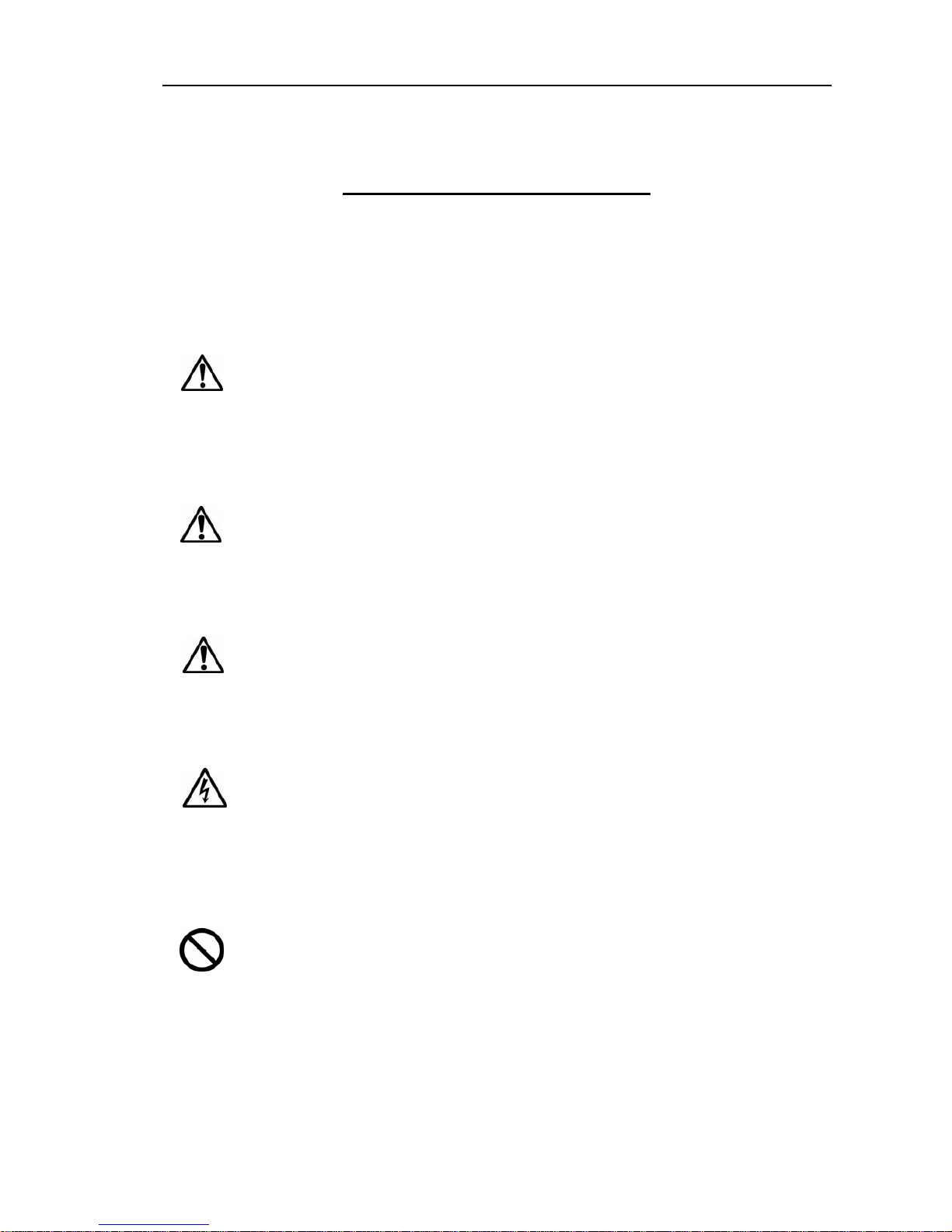
Various symbols used in this manual
The following symbols are used in this manual. Y ou are requested to be fully aware of the meaning
of each symbol before carrying out inspection and maintenance on this radar system
Warning mark
Alarm mark
Caution mark
Warning High Voltage mark
Prohibition mark
To handle the equipment ignoring this sign may lead to fatal
damage or injury to human body.
Warning
To handle the equipment ignoring this sign may lead to injury to
human body or damage to the equipment.
Alarm
To handle the equipment ignoring this sign may lead to electrical
shock to human body.
This sign indicates that a specified action is prohibited. The
prohibited action will be shown in the vicinity of the mark.
To handle the equipment ignoring this sign may lead to a
malfunction of the equipment.
Caution
Page 8

Preface MDC-1840BB/1841BB/1860BB/1810BB/1820BB Series
Operation Manual
(4) 93142122-07
HOW TO USE THIS MANUAL
Scope of this manual
This manual provides necessary information for installation, operation and
maintenance of MDC-1800BB series radar systems.
Organization of this manual
This manual is divided into chapters for quick and easy finding of the information you
require. The titles and contents of each chapter are as follows:
Chapter 1: General Descriptions
- Outline of the equipment
- Equipment category
- EMC compliance statement
- System configuration
- Software type name used
Chapter 2: Equipment Supplied
- Standard equipment list
- Spare parts list
- Installation material list
- Optional items
Chapter 3: Technical Specifications
- Antenna specification
- Display specification
- ATA Specification
- Serial data and sentence used
- Power supply
- Compass Safe Distance
- Environmental specification
- Mechanical specification
Page 9

MDC-1840BB/1841BB/1860BB/1810BB/1820BB Series Preface
Operation Manual
93142122-07 (5)
Chapter 4: Installation
- Installation considerations
- Unpacking each component of the system
- Inspection of each component unit and accessories
- Setting the units
- Cable routing and connections
- Installation procedure
- Setting up after installation
- Setting up option
Chapter 5: Basic Operation
- Introduction
- Control panel layout
- Operating controls
- Getting started
- Basic radar operations
Chapter 6: Using The Menu
- RADAR MENU
- DISP MENU
- ADJUST MENU
- SYSTEM MENU
- MAINTENANCE MENU
- Operation of EPA
- Operation of ATA
- Operation of AIS
Chapter 7: Graphic Displays
- Entering Graphic Mode
- Selecting the Graphic Display/DISPLAY ITEM SELECT MENU
- Registering or modifying the NAVLINE data / NAVLINE DATA INPUT
MENU
Page 10

Preface MDC-1840BB/1841BB/1860BB/1810BB/1820BB Series
Operation Manual
(6) 93142122-07
Chapter 8: Trouble Shooting And On Board Servicing
- Information required for service
- Self diagnosis functions provided
- Trouble shooting
- On board servicing
Chapter 9: Maintenance
- Periodic inspection and cleaning
Chapter 10: Technical References
- Serial input data sentence detail
- Tracking data output sentence detail
- Radar output sentence detail
- Interface requirements
Page 11

MDC-1840BB/1841BB/1860BB/1810BB/1820BB Series Chapter 1
Operation Manual General Descriptions
93142122-07 Contents
Chapter 1
General Descriptions
Contents
Page No.
1.1 Outline of the equipment.........................................................1-1
1.2 Equipment category.................................................................1-1
1.3 EMC compliance statement.....................................................1-1
1.4 System configuration...............................................................1-2
1.5 Software type name used........................................................ 1-3
Page 12

MDC-1840BB/1841BB/1860BB/1810BB/1820BB Series Chapter 1
Operation Manual General Descriptions
93142122-07 1-1
Chapter 1 General Descriptions
1.1 Outline of the equipment
The MDC-1800BB series of radar is designed and manufactured to meet the IEC
technical standards, shown below.
z IEC 60945 4th Edition 2002, General
z IEC 60872-2 and 3: EPA and ATA
z IEC 61162-1 and 2: Digital Interface
z IEC/PAS 60936-5: AIS (display on Radar)
The equipment is composed of two units, the antenna and the processor . The antenna
unit comprises a 3ft, 4 ft or 6 ft aerial, which is mounted on the transceiver unit of
either 4kW(For MDC-1840BB/1841BB), 6kW(For MDC-1860BB), 12 kW (For
MDC-1810BB), or 25 kW (For MDC-1820BB) type. The 4 foot and 6 foot aerials are
encapsulated in a water-sealed, durable plastic case. The transceiver unit is
contained in a waterproof aluminum case.
1.2 Equipment category
The MDC-1800BB series of radar is composed of the component units in the following
categories, specified in the IEC 60945 4th edition, Para 4.4.
Antenna Unit
(Type RB715A, RW701A-03/04/06 + RB716A/RB717A/RB718A/719A):
Exposed to the weather (formerly Class X)
Display Unit (Type MRM-100):
Protected from the weather (formerly Class B)
Operation Unit (Type MRO-100):
Protected from the weather (formerly Class B)
1.3 EMC compliance statement
This series of equipment has been tested and verified by the QinetiQ UK, according to
the IEC 60945 4th Edition, in terms of Electro Magnetic Compatibility and atmospheric
durability against the maritime environment.
Page 13

Chapter MDC-1840BB/1841BB/1860BB/1810BB/1820BB Series
General Descriptions Operation Manual
1-2 93142122-07
1.4 System configuration
The MDC-1840BB, MDC-1841BB, MDC-1860BB, MDC-1810BB and MDC-1820BB
radar sets are configured as follows:
Refer to Figure 1 for the system configuration of this series.
MDC-1840BB
Component Unit Sub-unit Type name
Antenna Unit Not assigned
Aerial, 3-foot RW701A-03
Aerial, 4-foot RW701A-04
Transceiver RB716A (4kW)
Processor Unit MRM-100
Operation Unit MRO-100
MDC-1841BB
Component Unit Sub-unit Type name
Antenna Unit RB715A (4kW)
Processor Unit MRM-100
Operation Unit MRO-100
MDC-1860BB
Component Unit Sub-unit Type name
Antenna Unit Not assigned
Aerial, 4-foot RW701A-04
Aerial, 6-foot RW701A-06
Transceiver RB717A (6 kW)
Processor Unit MRM-100
Operation Unit MRO-100
Page 14

MDC-1840BB/1841BB/1860BB/1810BB/1820BB Series Chapter 1
Operation Manual General Descriptions
93142122-07 1-3
MDC-1810BB
Component Unit Sub-unit Type name
Antenna Unit Not assigned
Aerial, 4-foot RW701A-04
Aerial, 6-foot RW701A-06
Transceiver RB718A (12 kW)
Processor Unit MRM-100
Operation Unit MRO-100
MDC-1820BB
Component Unit Sub-unit Type name
Antenna Unit Not assigned
Aerial, 4-foot RW701A-04
Aerial, 6-foot RW701A-06
Transceiver RB719A (25 kW)
Processor Unit MRM-100
Operation Unit MRO-100
1.5 Software type name used
The MDC-1800BB series of radar uses the following type of software:
NOTE: The asterisk (*) shows revision code, varied from A to Z.
Software Type Application
KM-D56 * Radar logic board
KM-D62 * Gyro/Log Interface (Option: KSA-08A)
KM-D07 * ATA (Option: MRE-300)
KM-D63 * AIS Interface (Option: AIS-100)
Page 15

Chapter MDC-1840BB/1841BB/1860BB/1810BB/1820BB Series
General Descriptions Operation Manual
1-4 93142122-07
Serial Data IN/OUT
DC mains
10.8 – 41.6 VDC
(RB715A/716A/717A/718A)
21.6 – 41.6 VDC
(RB719A)
AC mains
100/115/200/230 VAC
This section is built into the Display unit
Data 1 (TX/RX)
Data 2 (TX/RX)
Data 3 (TX/RX)
PROCESSOR UNIT
Type MRM-100
ANTENNA UNIT
AERIAL Type
RW701A-03 (3ft), RW701A-04 (4ft) or RW701A-06 (6ft)
TRANSCEIVER Unit
Type RB716A(4kW), RB717A (6kW), RB718A (12 kW) or RB719A (25 kW)
Gyro/Log Interface
Type KSA-08A
(Option)
Bearing Signal
LOG Signal
Gyro Power Supply
(11-40 VDC)
Figure 1.1 System configuration of
MDC-1840BB/1841BB/1860BB/1810BB/1820BB series of radar
Connecting Cable
Type 242J159098B
Length: 15 m
DC Power cable
Type CW-256
Length: 3 m
AC/DC Rectifier
Type PS-010
AC Power Cable
Type: VV2D8
Length: 3 m
AIS Interface
Type AIS-100
(Option)
A TA Type MRE-300
(Option)
OPERATION UNIT
Type MRO-100
Display UNIT
(User supply)
CW-560 (Option)
Length: 2 m
Connecting Cable
Type 242J158055B
Length: 15 m
ANTENNA UNIT
ANTENNA Unit
T
yp
e RB715A(4kW
)
Page 16

MDC-1840BB/1841BB/1860BB/1810BB/1820BB Series Chapter 2
Operation Manual Equipment Supplied
93142122-07 Contents
Chapter 2
Equipment Supplied
Contents
Page No.
2.1 Standard equipment list...........................................................2-1
2.2 Spare parts list.......................................................................... 2-2
2.3 Installation material list............................................................ 2-2
2.4 Optional items .......................................................................... 2-3
Page 17

MDC-1840BB/1841BB/1860BB/1810BB/1820BB Series Chapter 2
Operation Manual Equipment Supplied
93142122-07 2-1
Chapter 2 Equipment Supplied
2.1 Standard equipment list
MDC-1840BB
No. Item name T y pe name Remark
Weight/length
Q’ty
1 Aerial RW701A-03/04 3ft / 4 ft 5 kg / 6 kg 1
2 Transceiver u nit RB716A 4 kW 16 kg 1
3 Processor unit MRM-100 5.5 kg 1
4 Operation unit MRO-100 2 kg 1
5 Connecting cable 242J159098B-15M
With connectors attached on
both ends
15 m 1
6 Power cable CW-256-2M
Cable with 5-pin connector on
one end and fly leads on the
other end
2 m 1
7 Display cable CW-560-2M
Cable with D-SUB connector
on both ends
2 m 1
8 S pare parts SP-100 See spare parts list Not specifie d 1 set
9 Installation materials M12-BOLT.KIT See installation material list Not specified 1 set
10 Documents
MDC-1800BSER.OME
Operation manual Not specified 1
MDC-1841BB
No. Item name T y pe name Remark
Weight/length
Q’ty
1 Antenna RB715A 4 kW, 2 ft ( Radome ) 10 kg 1
2 Processor unit MRM-100 5.5 kg 1
3 Operation unit MRO-100 2 kg 1
4 Connecting cable 242J158055B-15M
With connectors attached on
both ends
15 m 1
5 Power cable CW-256-2M
Cable with 5-pin connector on
one end and fly leads on the
other end
2 m 1
6 Display cable CW-560-2M
Cable with D-SUB connector
on both ends
2 m 1
7 S pare parts SP-100 See spare parts list Not specifie d 1 set
8 Installation materials M10-BOLT.KIT See installation material list Not specified 1 set
9 Documents
MDC-1800BSER.OME
Operation manual Not specified 1
Page 18

Chapter 2 MDC-1840BB/1841BB/1860BB/1810BB/1820BB Series
Equipment Supplied Operation Manual
2-2 93142122-07
MDC-1860BB
No. Item name T y pe name Remark
Weight/length
Q’ty
1 Aerial RW701A-04/06 4 ft / 6 ft 6 kg / 8 kg 1
2 Transceiver u nit RB717A 6 kW 17 kg 1
3 Processor unit MRM-100 5.5 kg 1
4 Operation unit MRO-100 2 kg 1
5 Connecting cable 242J159098B-15M
With connectors attached on
both ends
15 m 1
6 Power cable CW-256-2M
Cable with 5-pin connector on
one end and fly leads on the
other end
2 m 1
7 Display cable CW-560-2M
Cable with D-SUB connector
on both ends
2 m 1
8 S pare parts SP-100 See spare parts list Not specifie d 1 set
9 Installation materials M12-BOLT.KIT See installation material list Not specified 1 set
10 Documents
MDC-1800BSER.OME
Operation manual Not specified 1
MDC-1810BB
No. Item name T y pe name Remark
Weight/length
Q’ty
1 Aerial RW701A-04/06 4 ft / 6 ft 6 kg / 8 kg 1
2 Transceiver unit RB718A 12 kW 17 kg 1
3 Processor unit MRM-100 5.5 kg 1
4 Operation unit MRO-100 2 kg 1
5 Connecting cable 242J159098B-15M
With connectors attached on
both ends
15 m 1
6 Power cable CW-256-2M
Cable with 5-pin connector on
one end and fly leads on the
other end
2 m 1
7 Display cable CW-560-2M
Cable with D-SUB connector
on both ends
2 m 1
8 S pare parts SP-100 See spare parts list Not specifie d 1 set
9 Installation materials M12-BOLT.KIT See installation material list Not specified 1 set
10 Documents
MDC-1800BSER.OME
Operation manual Not specified 1
Page 19

MDC-1840BB/1841BB/1860BB/1810BB/1820BB Series Chapter 2
Operation Manual Equipment Supplied
93142122-07 2-3
MDC-1820BB
No. Item name T y pe name Remark
Weight/length
Q’ty
1 Aerial RW701A-04/06 4 ft / 6 ft 6 kg / 8 kg 1
2 Transceiver unit RB719A 25 kW 21 kg 1
3 Processor unit MRM-100 5.5 kg 1
4 Operation unit MRO-100 2 kg 1
5 Connecting cable 242J159098B
With connectors attached on
both ends
15 m 1
6 Power cable CW-256-2M
Cable with 5-pin connector on
one end and fly leads on the
other end
2 m 1
7 Display cable CW-560-2M
Cable with D-SUB connector
on both ends
2 m 1
8 S pare parts SP-100 See spare parts list Not specified 1 set
9 Installation materials M12-BOLT.KIT See installation material list Not specified 1 set
10 Documents
MDC-1800BSER.OME
Operation manual Not specified 1
2.2 Spare parts list
MDC-1841BB (Common use)
No Description Rating Remark
Shape (Dimensions)
Q’ty Use
1
Fuse 15A Normal blow
Tubular (
φ
6.3 x 32)
2 Main power supply
2
Fuse 5A Normal blow
Tubular (
φ
5 x 25)
2 Motor power supply
3
Fuse 0.3A Normal blow
Tubular (
φ
5 x 25)
2 High voltage power supply
MDC-1840BB/1860BB/1810BB/1820BB (Common use)
No Description Rating Remark
Shape (Dimensions)
Q’ty Use
1
Fuse 15A Normal blow
Tubular (
φ
6.3 x 32)
2 Main power supply
2
Fuse 5A Normal blow
Tubular (
φ
5 x 25)
2 Motor power supply
3
Fuse 0.3A Normal blow
Tubular (
φ
5 x 25)
2 High voltage power supply
4
Motor brush 24Z125209B Not specified Not specified 1 set Antenna motor
Page 20

Chapter 2 MDC-1840BB/1841BB/1860BB/1810BB/1820BB Series
Equipment Supplied Operation Manual
2-4 93142122-07
2.3 Installation material list
MDC-1841BB
No Description Rating Q’ty Use
1 Hexagonal bolt B10X25U 4 Antenna unit
2 Plain washer 2W10U 8 Antenna unit
3 Spring washer SW10U 4 Antenna unit
4 Ferrite core E04RA400270150 1 Processor unit
MDC-1840BB/1860BB/1810BB/1820BB (Common use)
No Description Rating Q’ty Use
1 Hexagonal bolt B12X55U 4 Antenna unit
2 Nut N12U 8 Antenna unit
3 Plain washer 2W12U 8 Antenna unit
4 Spring washer SW12U 4 Antenna unit
5 Ferrite core E04RA400270150 1 Processor unit
2.4 Optional items
MDC-1840BB/1841BB/1860BB/1810BB/1820BB (Common use)
No. Description Rating Remark Weight/length/Q’ty
1 Gyro/Log Interface KSA-08A
Built into the display unit
Not specified
2 ATA MRE-300 Built into the display unit Not specified
3 AIS Interface AIS-100 Built into the display unit Not specified
CW-387-5M
One end with 8-pin connector
and flying leads on the other
end
for AIS (5 m)
CW-376-5M
One end with a 6-pin
connector and flying leads on
the other end
for GPS etc.
(5 m)
CW-388-5M
One end with 10-pin
connector and flying leads on
the other end
for Gyro/Log
(5 m)
4
Navigator
connecting cable
CW-561-10M
With 12-pin connector on
both ends
for REMOTE
(10 m)
5 Display cable CW-560-2M
With 15-pin connectors on
both ends
for Display
Monitor (2 m)
6 Rectifier PS-010 With two 5 A fuses 3.5 kg
7 AC power cable VV-2D8-3M Flying leads on both ends 3 m
242J158055C-20M 20 m
242J158055D-30M 30 m
8
Connecting cable in
extra length for
RB715A
242J158055E-XM
(See NOTE)
Connectors attached on both
ends
100 m max
Page 21

MDC-1840BB/1841BB/1860BB/1810BB/1820BB Series Chapter 2
Operation Manual Equipment Supplied
93142122-07 2-5
242J159098C-20M 20 m
242J159098D-30M 30 m
9
Connecting cable in
extra length for
RB716A/RB717A/
RB718A/RB719A
242J159098E-XM
(See NOTE)
Connectors attached on both
ends
100 m max
NOTE: The length of the cable is specified by the customer within 100 meters
Page 22

MDC-1840BB/1841BB/1860BB/1810BB/1820BB Series Chapter 3
Operation Manual Technical Specification
93142122-07 Contents
Chapter 3
Technical Specification
Contents
Page No.
3.1 Antenna specification .............................................................. 3-1
3.2 Display specification................................................................ 3-1
3.3 ATA specification (Option)....................................................... 3-2
3.4 AIS specification (Option)........................................................ 3-2
3.5 Serial data and sentence used................................................3-2
3.6 Power Supply............................................................................ 3-3
3.7 Compass Safe Distance...........................................................3-3
3.8 Environmental specification.................................................... 3-3
3.9 Mechanical specification ......................................................... 3-4
Page 23

MDC-1840BB/1841BB/1860BB/1810BB/1820BB Series Chapter 3
Operation Manual Technical Specifications
0093142122-08 3-1
Chapter 3 Technical Specifications
3.1 Antenna specification
Model name
MDC-1840BB MDC-1841BB MDC-1860BB MDC-1810BB MDC-1820BB
Aerial length
3 feet / 4 feet 2 feet 4 feet / 6 feet
Peak power
output
4kW 6kW 12kW 25kW
Frequency
9410 +/- 30 MHz
Beam width
Horizontal
2.5
o
/ 1.8o 3.9o 1.8o / 1.2
Vertical
22
o
25o 22o
Side lobes
Within +/- 10
o
Better than
–23dB
Better than
–20dB
Better than –23dB
Outside +/- 10o
Better than
–30 dB
Better than
–20dB
Better than –30 dB
Rotation
24/48 r.p.m.
Transmission pulse
4 kW 6 kW/12 kW 25 kW
width S (Short
pulse)
0.08 μs / 2000 Hz 0.08 μs / 4000 Hz 0.08μs/2000Hz
M1 (Medium 1
pulse)
0.25 μs / 1500 Hz 0.25 μs / 2000 Hz 0.3μs/1300Hz
M2 (Medium 2
pulse)
0.8 μs / 600 Hz 0.5 μs / 1000 Hz 0.6μs/800Hz
L (Long pulse)
0.8 μs / 600 Hz 1.0 μs / 500 Hz
1.2 μs / 500Hz,
450Hz(96NM)
IF center
frequency
60 MHz
IF bandwidth
15 MHz (S, M1) / 3 MHz (M2, L)
Noise figure
Better than 6 dB
Operation in wind
100 knots as relative
Water proofing
grade
IPX6 (IEC60529)
3.2 Processor specification
Effective
diameter
269 mm (at 18 inch LCD monitor)
Resolution
1280 x 1024 pixels
Video level
8 levels
Presentation
mode
Head-up, north-up, course-up and true motion
Range scale
(NM)
1/8 1/4 1/2 3/4 1.5 3 6 12 24 48 (4 kW) 64 (6 kW) 72 (12 kW) 96 (25 kW)
Rings interval
(NM)
1/16 1/8 1/4 1/2 1 2 4 8 (4 kW) 16 (6 kW) 12 (12 kW) 16 (25 kW)
Off-centering
Sweep origin can be moved to any point within 2/3 of the screen radius.
Page 24

Chapter 3 MDC-1840BB/1841BB/1860BB/1810BB/1820BB Series
Technical Specifications Operation Manual
3-2 0093142122-08
Trail display
interval
Every scan, 15 sec, 30 sec, 1 min, 3 min, 6 min, 12 min and OFF
Alarm Entry alarm [alarm range (Minimu m 0.5 NM), depth and bearing can be
varied]
EPA
Up to 10 targets can be plotted, 5 points for one target each
ATA (Option) Display of acquire/track data of up to 10 targets and Guard Zone are
available. Display of guard zone is also available (any alarm range, width
and bearing can be set).
Data available
for EPA and ATA
Speed, course, CPA, TCPA, distance, bearing and age (time elapsed
since the first plot, applicable to EPA only).
Minimum
detectable range
20 meters at 1/8 nm range
Range
resolution
20 meters at 1/8 nm range
Range data
accuracy
70 meters or 1% of the range scale selected, whichever is the greater.
Bearing data
accuracy
+/-1
o
maximum
Navigation data
display
Data of own ship’s position (latitude/longitude)
3.3 ATA specification (Option)
Acquisition Manual
Tracking Automatic
Number of targets tracked Up to 10 targets
Numerical data output Distance, bearing, speed, CPA and TCPA
Alarm Collision alarm and lost alarm
On screen display
Symbols (acquired target, tracked target, target with
data display and lost target), target number and
vectors.
Display mode Relative and True
Tracking distance range Up to 40.0 nm
ATA data output
To be taken via the DATA 1 connector on the display
rear panel.
Signal level: RS422
Data format: IEC1162-1
Page 25

MDC-1840BB/1841BB/1860BB/1810BB/1820BB Series Chapter 3
Operation Manual Technical Specifications
0093142122-08 3-3
3.4 AIS specification (O ption)
Number of targets displayed Up to 64 activated targets and sleeping targets in total
Numerical data indication MMSI, CPA, TCPA, CSE/COG, STW/SOG
On screen display
Symbols, target number and vectors.
Indication limit range 1.0 to 20.0 nm
AIS data input
To be taken via the AIS connector on the display rear panel.
Signal level: RS422
Data format: IEC61162-2
Formatter: ALR, VDO, VDM
3.5 Serial data and sentence used
Serial data: IEC 61162-1 or NMEA 0183 ver 2.30
Sentence: BWC, GGA, GLC, GLL, HDT, RMB, RTE, VBW, VDR, VHW, VTG, WPL
3.6 Power Supply
Mains Input Voltage: 24 VDC / 32 VDC
Input Voltage Tolerance: 10.8 VDC – 41.6 VDC
(for MDC-1840BB/1841BB/1860BB/1810BB)
21.6 VDC – 41.6 VDC (for MDC-1820BB)
Input Power: 170 W nominal at 24 VDC
Transient Protection:
To the requirements of IEC 60945 4th Edition.
Reversed polarity protection: Protected by the Main Fuse.
AC Operation
Rectifier Unit Type PS-010 is required.
Input voltage range: 115/230 VAC
Input voltage tolerance: +/- 10%
Input voltage frequency range: 47 to 63 Hz
Input Power: 220 W
3.7 Compass Safe Distance
Component Unit Type Name Standard Steering
Antenna
RB715A 1.4 m 0.95 m
RB716A/RW701A-03 1.4 m 0.95 m
RB716A/RW701A-04 1.4 m 0.95 m
RB717A/RW701A-04 1.4 m 0.95 m
RB717A/RW701A-06 1.4 m 0.95 m
Page 26

Chapter 3 MDC-1840BB/1841BB/1860BB/1810BB/1820BB Series
Technical Specifications Operation Manual
3-4 0093142122-08
Antenna
RB718A/RW701A-04 1.4 m 0.95 m
RB718A/RW701A-06 1.4 m 0.95 m
RB719A/RW701A-04 1.4 m 0.95 m
RB719A/RW701A-06 1.4 m 0.95 m
Processor Unit MRM-100 1.6 m 1.15 m
Operation Unit MRO-100 0.60 m 0.40 m
3.8 Environmental specification
To the requirements of IEC 60945 4th Edition. The measure environmental
specifications are as follows:
(1) Temperature and humidity
Operating temperature Storage temperature Humidity
Antenna -25oC - +55oC +70oC 93%+/-3% at +40oC
Processor -15oC - +55oC +55oC 93%+/-3% at +40oC
(2) Vibration
2-5Hz up to 13.2 Hz: Amplitude +/-1mm +/-10% (Maximum acceleration 7m/s2 at
13.2Hz)
13.2 Hz up to 100Hz: Maximum acceleration 7 m/s2 constant
3.9 Mechanical specification
Dimensions: W (Width) x Depth x Height, Unit in mm
Weight: Unit in kg
Antenna:
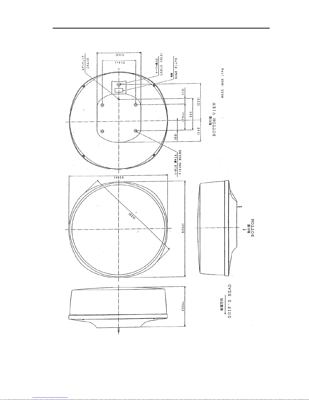
RB715A: 636 x 636 x 255, 10kg
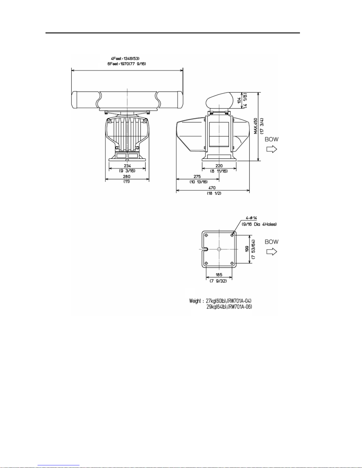
RB716A: 280 x 390 x 450, 21 kg (for 3ft system), 22 kg (for 4ft system)
RB717A/718A: 280 x 390 x 450, 23 kg (for 4ft system), 25 kg (for 6ft system)
RB719A: 280 x 470 x 450, 27 kg (for 4ft system), 29 kg (for 6ft system)
Aerial Swing circle: 1034 for 3 ft, 1346 for 4 ft, 1970 for 6 ft
Processor unit (MRM-100):
320 x 122 x 320, 5.5 kg
Operation unit (MRO-100):
354 x 130 x 49, 2 kg
Page 27
MDC-1840BB/1841BB/1860BB/1810BB/1820BB Series Chapter 3
Operation Manual Technical Specifications
0093142122-08 3-5
Unit in mm
(
inch
)
Figure 3.1 External dimensions of the Antenna unit, RB715A
Page 28

Chapter 3 MDC-1840BB/1841BB/1860BB/1810BB/1820BB Series
Technical Specifications Operation Manual
3-6 0093142122-08
Figure 3.2 External dimensions of the Antenna unit, RB716A
Page 29

MDC-1840BB/1841BB/1860BB/1810BB/1820BB Series Chapter 3
Operation Manual Technical Specifications
0093142122-08 3-7
[Antenna unit]
Figure 3.3 External dimensions of the Antenna unit, RB717A / RB718A
Page 30
Chapter 3 MDC-1840BB/1841BB/1860BB/1810BB/1820BB Series
Technical Specifications Operation Manual
3-8 0093142122-08
Figure 3.4 External dimensions of the Antenna unit, RB719A
Page 31

MDC-1840BB/1841BB/1860BB/1810BB/1820BB Series Chapter 3
Operation Manual Technical Specifications
0093142122-08 3-9
Figure 3.5 External dimensions of the Processor unit, MRM-100
[Processor unit]
Figure 3.6 External dimensions of Operation Unit, MRO-100
[Operation unit]
Page 32

MDC-1840BB/1841BB/1860BB/1810BB/1820BB Series Chapter 4
Operation Manual Installation
93142122-07 Contents
Chapter 4
Installation
Contents
Page No.
4.1 Installation considerations ......................................................4-1
4.2 Unpacking each component of the system............................4-1
4.3 Inspection of each component unit and accessories...........4-1
4.4 Setting the units .......................................................................4-1
4.4.1 Antenna Unit........................................................................................4-1
4.4.2 Processor Unit and Operation Unit......................................................4-2
4.5 Cable routing and connections............................................... 4-2
4.5.1 Antenna...............................................................................................4-2
4.5.2 Processor Unit.....................................................................................4-3
4.6 Installation procedure ..............................................................4-3
4.6.1 Installing the Transceiver Unit..............................................................4-3
4.6.2 Fitting the Aerial...................................................................................4-4
4.6.3 Connecting the cable...........................................................................4-5
4.6.4 Installing the Processor Unit................................................................4-6
4.6.5 Installing the Operation Unit ................................................................4-8
4.6.5.1 Table mounting..........................................................................4-8
4.6.5.2 Flush mounting.......................................................................4-10
4.6.6 Connecting the cable to the Display unit...........................................4-12
4.6.7 Link setting for the gyroco mpass.......................................................4-13
4.6.8 Ferrite core assembling for Power cable .............................................4-14
4.7 Setting up after installation ................................................... 4-15
4.7.1 Auto tune adjustment.........................................................................4-15
4.7.2 Transmission timing...........................................................................4-16
4.7.3 Ship’s heading setup.........................................................................4-17
4.7.4 Resetting Manual GAIN/STC (Height)/Manual STC..........................4-17
4.7.4.1 Manual GAIN setting...............................................................4-17
4.7.4.2 STC (Height) setting...............................................................4-18
4.7.4.3 Manual STC setting................................................................4-19
Page 33

Chapter 4 MDC-1840BB/1841BB/1860BB/1810BB/1820BB Series
Installation Operation Manual
Contents 93142122-07
Page No
4.8 Setting up option....................................................................4-21
4.8.1 AIS Interface (Option) ....................................................................... 4-21
4.8.2 Remote Display operation................................................................. 4-21
4.8.2.1 Connecting the Remote Display............................................. 4-21
4.8.2.2 Required set up...................................................................... 4-21
4.8.2.3 Possible operation on Remote Display................................... 4-21
APPENDIX 1....................................................................................4-24
Installation of the ATA module, MRE-300........................................................... 4-24
Installation of the AIS module, AIS-100.............................................................. 4-24
Installation of the Gyro Interface module, KSA-08A........................................... 4-25
APPENDIX 2....................................................................................4-28
Optional cables pinouts and cable color-coding designation ............................. 4-28
APPENDIX 3....................................................................................4-29
Recommended TFT Display .............................................................................. 4-29
Page 34

MDC-1840BB/1841BB/1860BB/1810BB/1820BB Series Chapter 4
Operation Manual Installation
0093142122-11 4-1
Chapter 4 Installation
4.1 Installation considerations
General
Qualified service personnel should perform the installation of the MDC-1800BB series.
The installation comprises the following operations.
(1) Unpacking each component of the system.
(2) Inspection of the exterior of each component unit and accessory.
(3) Checking the ship’s mains voltage and current capacity.
(4) Determining the site of installation
(5) Installing the Antenna Unit.
(6) Installing the Display Unit
(7) Installing the accessory items
(8) Planning the cable routing and connections
(9) Commissioning
4.2 Unpacking each component of the system
Unpack your package and check if all of the items stated in the packing list are
contained in the package. If not, report this to the insurance agent for tracing missing
goods or refund.
4.3 Inspection of each component unit and accessories
Carefully check the exterior of each component unit for dents, damage, etc. Also
check the inside of component units for electrical and mechanical damage. The
Cathode Ray Tube is a fragile item, which is easily broken if the display unit is
accidentally dropped.
4.4 Setting the units
To achieve best operational performance, the following factors must be considered.
4.4.1 Antenna Unit
(1) The radar antenna should be mounted on the center line of your ship where no
large obstacles interfere with the path of the radar beam.
(2) Location should be as high as possible, however, keep in mind that nearby objects
may be overlooked if mounted too high. Also note that the higher the antenna, the
higher the level of sea clutter.
(3) The mounting surface should be as flat as possible and approximately parallel
with the vessel’s water line.
Page 35

Chapter 4 MDC-1840BB/1841BB/1860BB/1810BB/1820BB Series
Installation Operation Manual
4-2 0093142122-11
(4) The antenna unit should be positioned forward of large structure and exhaust
stacks, to avoid causing blind sectors on the radar screen as well as
contamination from engine exhaust on the radar antenna aperture.
(5) Provide sufficient servicing space.
4.4.2 Processor Unit, Operation Unit and Display
Processor Unit:
(1) Select a position safe and free of dampness, water spray, rain and direct sunlight.
(2) Provide enough space for servicing.
Operation Unit:
(1) Select a position near the display for easy access and operation. Also consider the
length of the connecting cable that is 2 m.
Display (User purchased item):
(1) Position the display unit as far as possible away from other radio equipment.
(2) Keep a safe distance from the magnetic compass: standard: x.xx m, steering: x.xx
m.
(3) Select a location that provides good observation to radar screen and outside
environment.
(4) Locate the display so that it provides easy viewing from all likely operator’s
positions.
(5) Select a position safe and free of dampness, water spray, rain and direct sunlight.
(6) Provide enough space for servicing. Consider access to the rear panel for
connecting various cables.
(7) Position the display unit as far as possible away from other radio equipment.
4.5 Cable routing and connections
4.5.1 Antenna
(1) The cable connecting the antenna and display should be run separately away from
other cables such as, radio antenna feeders, power cables, etc. Under no
circumstances should it be in parallel arrangement with other cables. These
precautions are essential to avoid radio interference to/from other equipment
installed on the ship. If this is not possible, either cable set should be screened
with metal conduit or another form of shielding.
(2) Cable should be run as short as possible but be kept within the standard length to
achieve best radar performance.
(3) The copper braids of the cable must be grounded via a grounding stud in the
transceiver unit.
Page 36

MDC-1840BB/1841BB/1860BB/1810BB/1820BB Series Chapter 4
Operation Manual Installation
0093142122-11 4-3
4.5.2 Processor Unit
(1) The processor unit must be grounded to the hull via a grounding stud at the rear of
the processor unit.
4.6 Installation procedure
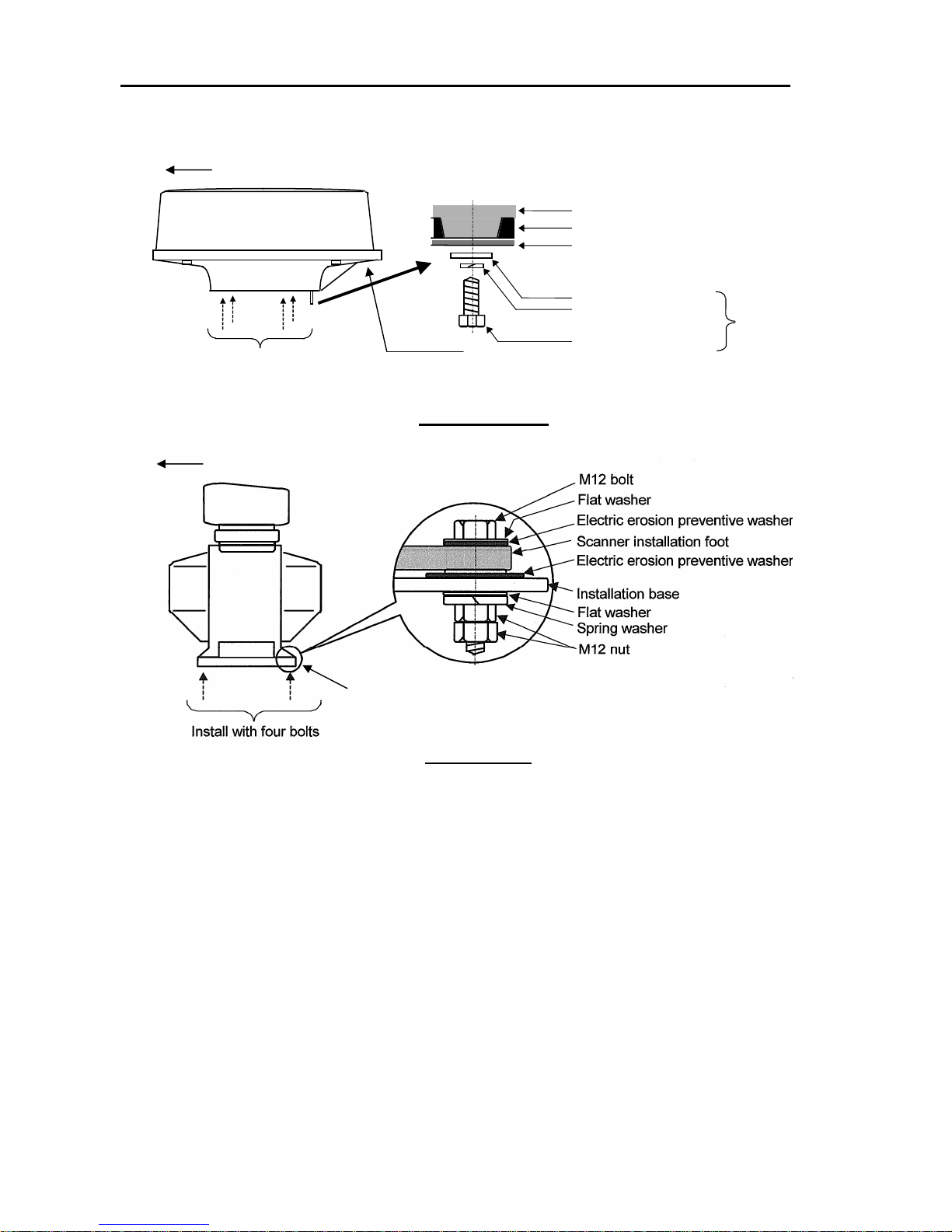
4.6.1 Installing the Transceiver Unit
When mounting the unit, position the transceiver unit as shown, so that a notched part
of the transceiver base is directed towards the aft. This arrangement simplifies cable
fitting and servicing. Also take note of the precautions detailed in paragraph 4.4.1
when you attempt to install the antenna unit.
(1) Drill four fixing holes of 14 mm (12 mm for Radome) diameter on the fitting
surface of a radar platform, as shown in Figure 4.1.
(2) Fit the transceiver unit on the position and fix it using the 12 mm (10 mm for
Radome) stainless bolts prepared as installation materials.
Figure 4.1 Plan view of fixing holes
(0.55)
4-φ14
Center
214
170
4-φ12
Unit:mm (inch)
65
(8.43)
(2.56
)
(0.47)
(6.69)
199
(7.83)
Forward
185
(
7.28 in.
)
Rotation Radius
R550 (3 ft antenna)
R700 (4 ft antenna)
Radome scanner
Open scanner
35
(1.38)
φ15(0.59)
(For Air Tube)
φ100(39.7)
(For Cable Inlet)
Page 37
Chapter 4 MDC-1840BB/1841BB/1860BB/1810BB/1820BB Series
Installation Operation Manual
4-4 0093142122-11
Figure 4.2 Details of the base fixing
Fix four screws
Mount base
Washer
Spring washer
M10 Hexagonal bolt
Radome(bottom)
Chassis
Included
Radome scanner
Ship’s heading
Cable inlet
Cable recess provided here
Ship’s heading
Open scanner
Page 38
MDC-1840BB/1841BB/1860BB/1810BB/1820BB Series Chapter 4
Operation Manual Installation
0093142122-11 4-5
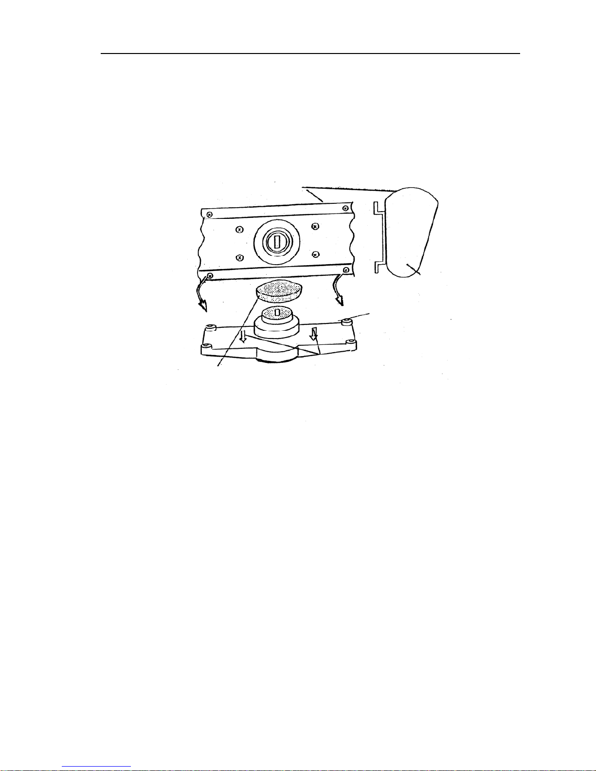
4.6.2 Fitting the Aerial
(1) Remove the protection cap on the outlet of the rotating base.
(2) Fit the aerial on to the rotating base. Orient the aerial front face (the company logo
printed on it) to the direction to which two arrow-marks on the rotating base point.
(3) Fix the aerial with four bolts attached to the aerial base.
Figure 4.3 Fitting the aerial onto the rotating base
Aperture
Aerial
Rotating base
Arrow Mark
Protection cap
Rotating base
Spring
Fixing Bolt
Page 39

Chapter 4 MDC-1840BB/1841BB/1860BB/1810BB/1820BB Series
Installation Operation Manual
4-6 0093142122-11
4.6.3 Connecting the cable
4.6.3.1 Connecting the cable for the Radome type scanner
1) Be sure that the power is off.
2) Remove the upper part of the radome from the scanner unit. Lift it vertically to
avoid bumping it against the antenna. (There are four fixing screws.)
3) Remove the tape securing the antenna.
4) Remove the shield cover located on the backside. (There are four screws.)
5) Remove the cable clamping plate and rubber ring, pass the cable through the
opening, replace the rubber ring, and clamp the cable to the scanner unit with screws
on the fixing plate. Attach the 7-pin connector to X11 and 9-pin connector to X12 of
the printed circuit board.
6) Replace the aluminum cover. Lay the cable shield into the channel machined into
the aluminum housing. Be careful that the cable will not get caught up between the
main unit and cover.
Replace the upper part of the radome being careful not to bump it against the antenna.
Make sure that the cover is positioned in the correct direction as shown in Figure4.4.
The upper and lower parts of the radome each have four alignment markings
indicating screw positions.
Connect the cable to the plug labeled "SCANNER" on the rear panel of the display
unit. Be sure to secure the rubber boot around the cable connector rim.
Ship's
heading
Logo seal on
side wall
Fix four screws
Cable inlet
Figure 4.4 Fitting cover
Page 40

MDC-1840BB/1841BB/1860BB/1810BB/1820BB Series Chapter 4
Operation Manual Installation
0093142122-11 4-7
Fix connector on
PCB(X11, X12)
Stern side
Shield cover
Cable shield
Radome (bottom)
Fixing plate
Rubber ring
Interconnecting cable
X12 (Connect here
)
Radome (bottom)
PCB
Inner shield
X11 (Connect here
)
Figure 4.5 Connecting the cable to the antenna
Page 41

Chapter 4 MDC-1840BB/1841BB/1860BB/1810BB/1820BB Series
Installation Operation Manual
4-8 0093142122-11
4.6.3.2 Connecting the cable for the Open type scanner
(1) Remove the front and rear covers by loosening fixing bolts (4 bolts each).
(2) Remove the TR(transceiver) unit by removing two fixing bolts. Make sure the
magnetron fitted on the transceiver does not attract any magnetizing material.
(3) Remove the rubber sealing, washer, and retainer plate from the antenna cable.
(4) Feed the cable through the access hole through to the inside of the antenna unit.
(5) Slide the rubber sealing, washer and retainer plate onto the cable.
(6) Fix the cable retainer plate over the dressed braid using three fixing bolts.
(7) Fix the antenna cable with the cable clamp.
(8) Connect the antenna cable to the Modulator PCB. (Refer to the interconnection
diagram for detail)
Figure 4.6 Connecting the cable to the antenna
TR unit fixing bolts
Remove these connectors
Fixing bolt
Fixing plate
Interconnection cable
Clump
5 mm maximum
Fixing bolt
Cable shield terminal
Washer
Fixing plate
Scanner unit
Connecting cable
Rubber water sealing
Cable inlet
Lay the braid under the fixing
plate as short as possible.
Peel off residual heat-shrink tube here
Page 42
MDC-1840BB/1841BB/1860BB/1810BB/1820BB Series Chapter 4
Operation Manual Installation
0093142122-11 4-9
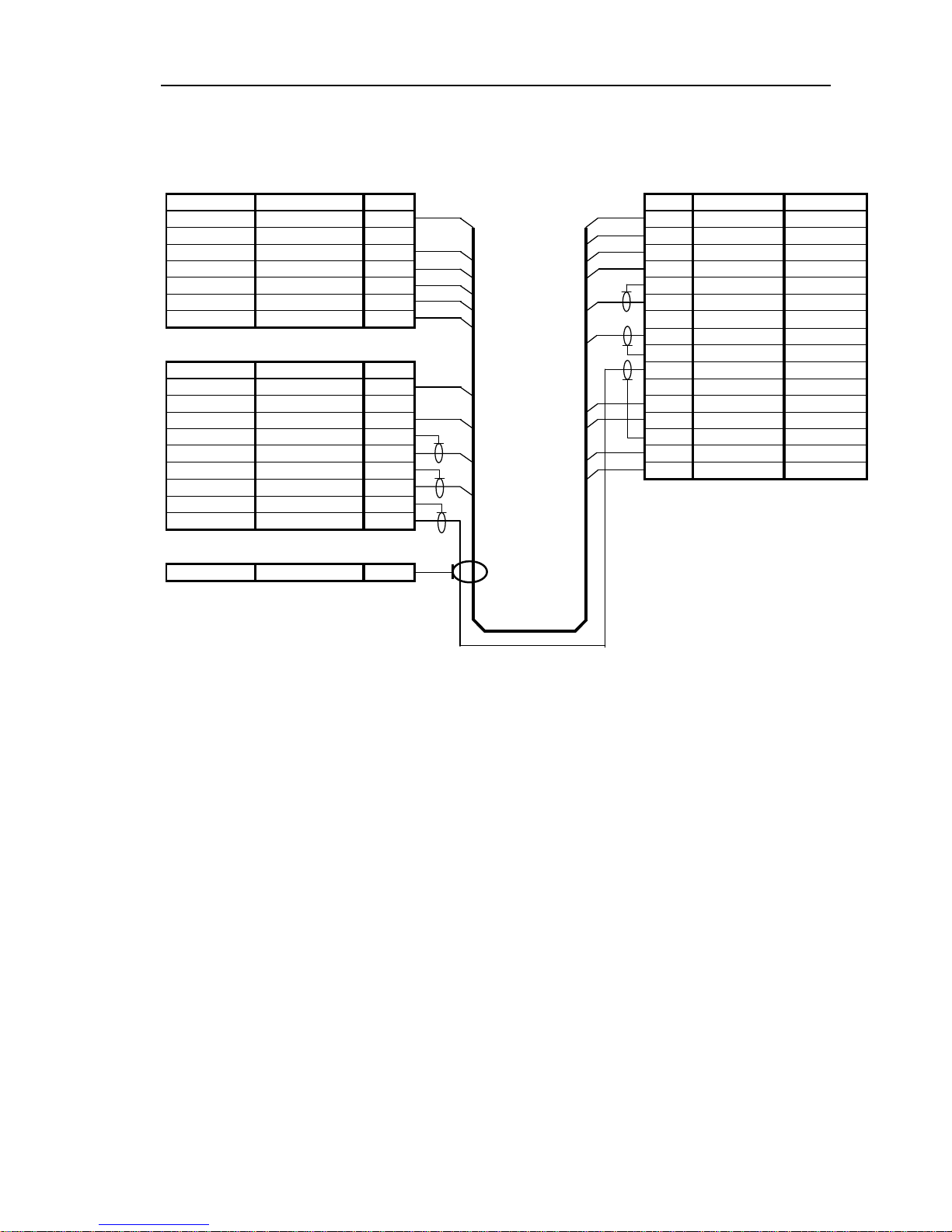
Figure 4.7 Interconnections between Antenna Unit and Display Unit
ANTENNA UNIT PROCESSOR UNIT
P1 PX
Description Color No. No. Color Description
+250V Violet 1 1 Violet +250V
NC NA 2 2 Blue +24V
GND Yellow 3 3 Orange(Larger) +12V
+40V Red(Larger) 4 4 Yellow GND
+40V Yellow (Larger) 5 5 Braid DATA-RTN
+40V-RTN Green (Larger) 6 6 Red (Coax) DATA
+40V-RTN Blue (Larger) 7 7 - -
8 Brown (Coax) BP/SHF
P2
9 Braid BP/SHF-RTN
Description Color No. 10 Gray (Coax) V/TRIG
+24V Blue 1 11 NC NA 2 12 Red(Larger) +40V
+12V Orange (Larger) 3 13 Yellow(Larger) +40V
DATA-RTN Braid 4 14 Braid V/TRIG-RTN
DATA Red (Coax) 5 15 Green(Larger) +40V-RTN
BP/SHF-R Braid 6 16 Blue(Larger) +40V-RTN
BP/SHF Brown (Coax) 7
V/TRIG-RTN Braid 8
V/TRIG Gray (Coax) 9
Grounding Lug
GND Braid 1
Page 43

Chapter 4 MDC-1840BB/1841BB/1860BB/1810BB/1820BB Series
Installation Operation Manual
4-10 0093142122-11
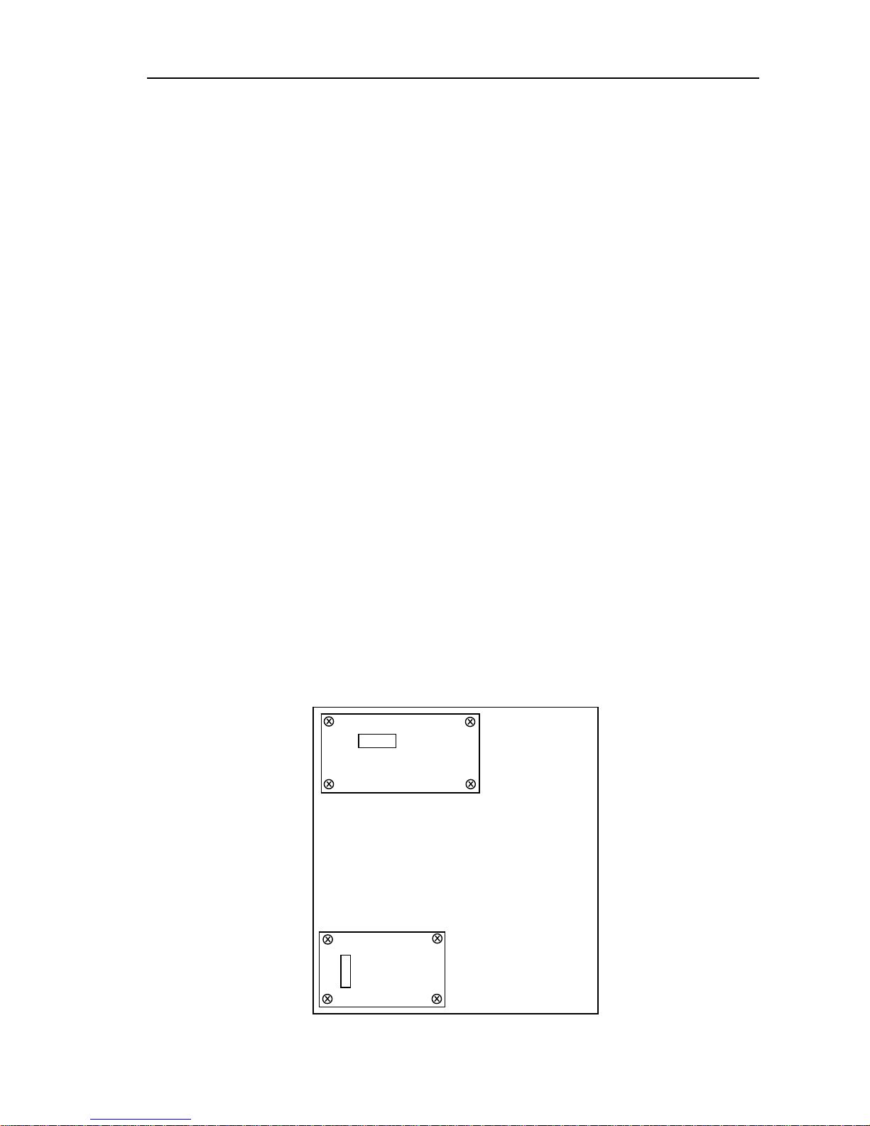
4.6.4 Installing the Processor Unit
The Processor Unit can be installed on tabletop or bulkhead. Use the following
procedure for installation.
(1) Determine the location observing the precaution given in Para 4.4.2.
(2) Place the Processor Unit onto the position where the unit is installed and fix it
using the truss tapping screws prepared in the installation material kit. (4 positions)
Figure 4.8 Installing the Processor Unit
Use M4 (4 mm) tapping screw with 25
mm length or more for good security.
(4 positions)
Page 44
MDC-1840BB/1841BB/1860BB/1810BB/1820BB Series Chapter 4
Operation Manual Installation
0093142122-11 4-11
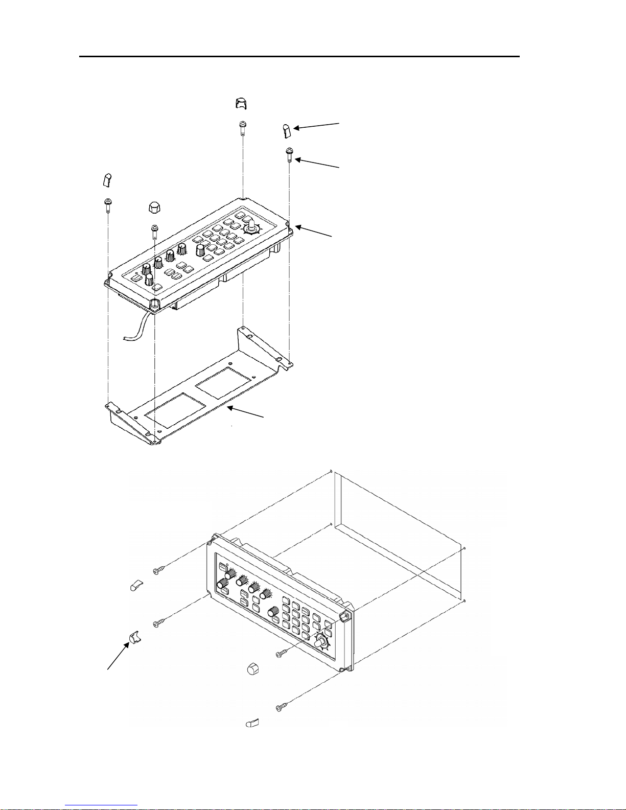
4.6.5 Installing the Operation unit
The Operation Unit can be installed in table mount or flush mount mode.
4.6.5.1 Table mounting
(1) Remove the screw cover (4 positions) at the corner of the operation unit. To do so,
insert a thin, flat screwdriver into a gap between the cover and the operation unit.
Apply gentle pressure to gradually pry the cover off the unit. The screw cover
comes off easily by sliding it upward.
(2) Remove the mounting bracket from the operation unit by loosening the M5 screw
(4 positions).
(3) Determine the place to install the bracket and mark the point of screw. (4 positions)
(4) Put the bracket in place and fix with M5 (5 mm) tapping screw. (4 positions)
Refer to Figure 4.10 and Figure 4.11 for detail.
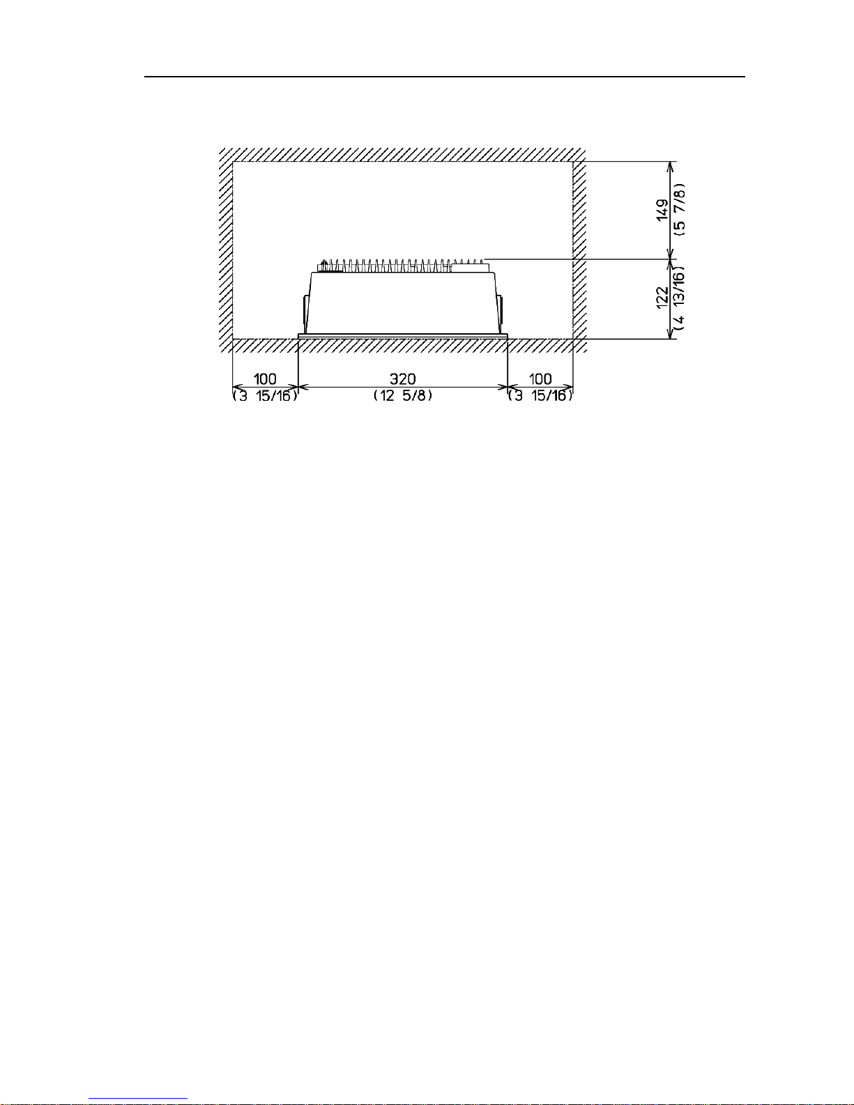
Figure 4.9 Service space required for the Processor Unit
Page 45

Chapter 4 MDC-1840BB/1841BB/1860BB/1810BB/1820BB Series
Installation Operation Manual
4-12 0093142122-11
Screw cover (4 positions)
Operation unit
M5 (5 mm) tapping screw (4 positions)
Mounting bracket
M5 (5 mm) Screw (4 positions)
Figure 4.10 Mounting the Control unit
Figure 4.11 Service space required for the Operation unit
Page 46

MDC-1840BB/1841BB/1860BB/1810BB/1820BB Series Chapter 4
Operation Manual Installation
0093142122-11 4-13
4.6.5.2 Flush mounting
Preparation:
(1) Cut aperture in surface to the dimensions shown below
(2) Mark the fixing points with a sharp-edged tool.
Installation:
(1) Remove the mounting bracket from the Control Box.
(2) Remove a screw cover, which is fitted on each corner of the Control Box front
face.
(3) Put the Control Box and connecting cable into the aperture and connect the cable
to the Processor unit at the specified receptacle. (Refer to Figure 4.15)
(4) Fasten the Control Box to the panel using a 4 mm tapping-screw. (4 positions)
(5) Refit the screw covers removed in step (2).
Figure 4.12 Dimensions of the Operation unit mounting aperture
Page 47
Chapter 4 MDC-1840BB/1841BB/1860BB/1810BB/1820BB Series
Installation Operation Manual
4-14 0093142122-11
Figure 4.13 Removing the Operation
Unit from the Mounting Bracket
Mounting bracket
Operation Unit
Screw covers (4 pcs)
M4 screws (4 pcs)
Figure 4.14 Installing the Operation Unit onto the console panel
M4 Tapping-screws (4 pcs)
Screw covers (4 pcs)
Page 48
MDC-1840BB/1841BB/1860BB/1810BB/1820BB Series Chapter 4
Operation Manual Installation
0093142122-11 4-15
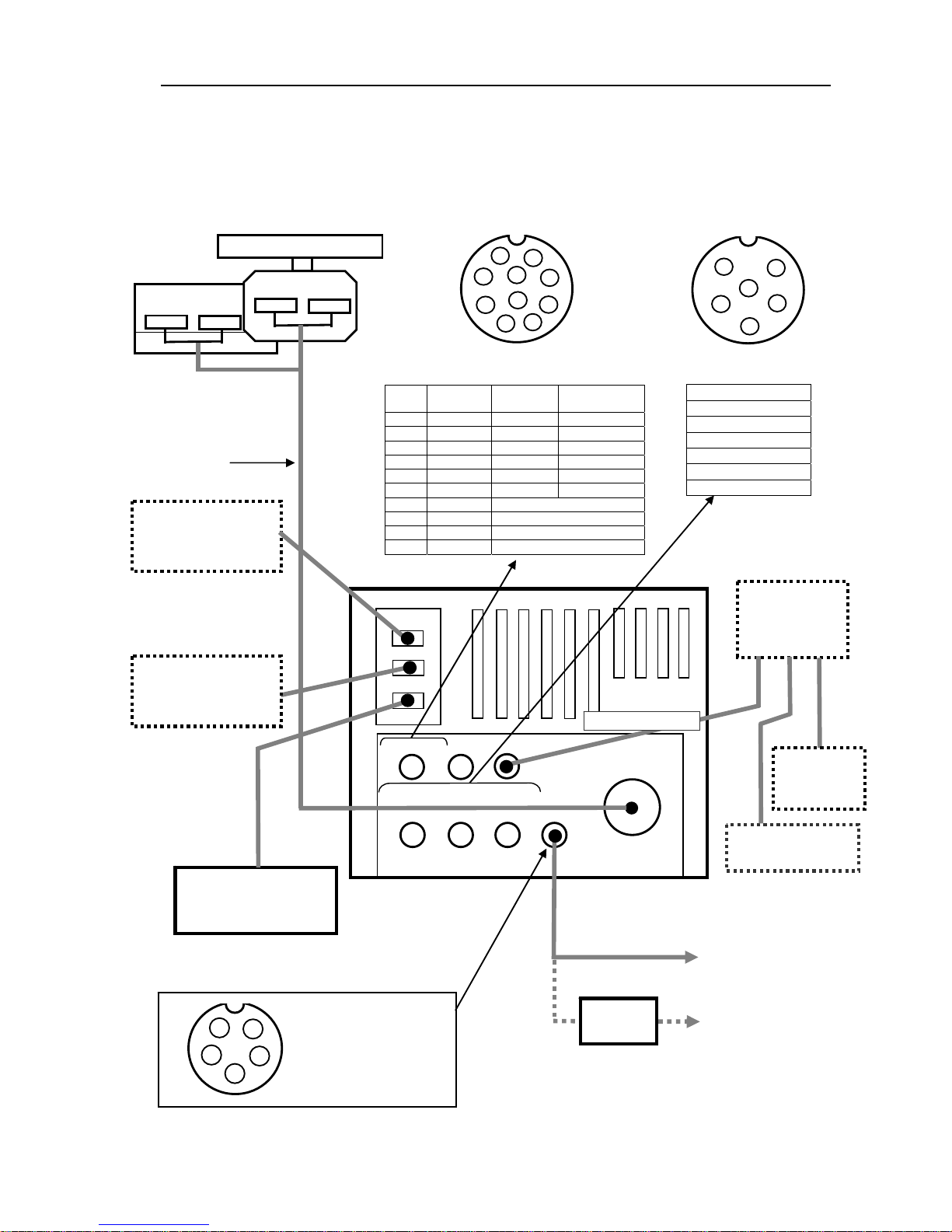
4.6.6 Connecting the cable to the Processor Unit
Connect the antenna cable, power cable and the data cable to the designated sockets
as shown in Figure 4.15.
Processor unit
Power supply for
Gyro/Log Interface
(11-40 VDC)
DC Main Supply
(21.6 – 41.6 VDC)
AC/DC Rectifier
PS-010
Pin assignment on Power Supply Connector
(Top view)
GYRO / LOG
No.1: Main DC (-)
No.2: Main DC (+)
No.3: Gyro I/FDC (+)
No.4: Gyro I/FDC (-)
No.5: Shield
1
2
3
1
2
3
4
5
6
Pin assignment on
Data Connector (Top view)
DATA 1,2 &3
No.1: Shield
No.2: OUT-A
N0.3: OUT-B
No.4: IN-A
No.5: IN-B
No.6: GND
Data connector pin assignment
Gyro/Log Connections
Pin
No.
NAME SYNC STEP
1 S1 X X
2 S2 X X
3 S3 X X
4 R1 X NC
5 R2 X NC
6 COM NC X
7 GND Frame ground
8 LOG 1 Mechanical contact signal
9 LOG 2 Mechanical contact signal
10 N.C.
Connecting cable
Type
242J159098B
L=15 m
Power cable
CW-256, L=2 m
AC cable
VV-2D8, L=3 m
(Option)
4
5
1
2
3
4
5
6
Pin assignment on
Data Connector (Top view)
7
8
9
10
SCANNER
DATA 1
DATA 2
DATA 3
Figure 4.15 Cable connections on the Display Unit
AIS*
REMOTE*
* See 4.8.1, 4.8.2
DISPLAY unit
(User supplied)
Processor
unit
(MRM-100)
Operation unit
(
MRO-100
)
DISPLAY
unit
Operation unit
(MRO-100)
Display cable
Type CW-560,
L=2 m
CW-561, L=10 m
VDR
Type
242J158055B
L=15 m
Page 49

Chapter 4 MDC-1840BB/1841BB/1860BB/1810BB/1820BB Series
Installation Operation Manual
4-16 0093142122-11
4.6.7 Link setting for the gyrocompass
When the Gyro signal voltage is lower than 50V, change the link positions for J721 to
J7125 from “2-3” to “1-2” on the Main Logic PCB (E47-700*) as shown below.
4.6.8 Ferrite core assembling for Power cable
Loop the power cable around the ferrite core three turns at position of 40 cm from the
connector as shown in figure 4.17.
1
2
3
1
2
3
Change setting from “2-3” to “1-2”,
applicable for J721 to J725
Main Logic PCB (E47-700*)
Main cabinet chassis
KSA-08A PCB module
(E47-510*)
Link pins for J721 to J725 for the
gyrocompass voltage setting
Figure 4.16 Locations of the gyrocompass links on the Main Logic PCB
Page 50

MDC-1840BB/1841BB/1860BB/1810BB/1820BB Series Chapter 4
Operation Manual Installation
0093142122-11 4-17
Figure 4.17 Ferrite core assembling for Power cable
Ferrite core
Connector
Page 51

Chapter 4 MDC-1840BB/1841BB/1860BB/1810BB/1820BB Series
Installation Operation Manual
4-18 0093142122-11
4.7 Setting up after installation
A few set ups are required after installation. Before carrying out the setting up
procedures, check the following items in order to make sure the equipment operates
in normal manner:
(1) Check that the ship’s power supply is properly rated to operate the radar system.
(2) No person is present near the platform or on the mast where the radar antenna is
to be operated. Put a warning tag on the display unit that reads, “RADAR
ADJUSTMENT IN PROCESS. DO NOT TOUCH ANY CONTROLS”.
4.7.1 Auto tune adjustment
Menu Item: ADJUST/ PRESET/ AUTO TUNE
It is necessary to adjust the AUTO TUNE for the best radar performance when
installed the radar, or replaced the magnetron.
NOTE: When operating the radar, the following error message happen to be
indicated on the screen in case of the first power on the radar after installation, or
leave the radar switched off for a long period;
"MAGNETRON HEATER CURRENT ABNORMAL", or "MAGNETRON
CURRENT ABNORMAL". If the message is indicated on the screen, please
ageing the magnetron first as follows.
1. Keep the radar OFF more than 20 minutes to wait the magnetron completely
cold.
2. Power ON the radar. Keep the radar to stand by state for an hour.
3. Transmit the radar at 0.25NM range scale for another one hour. Do not change
the range scale during the hour.
4. If above error message is indicated on the screen during this 0.25NM range
operation, start again from item #1.
If the error message is indicated on the screen and stop the transmission even
finish the ageing with above procedure, some problem may happen on the radar.
Please contact to our local dealer.
NOTE: The following setup menus are protected from ordinary key operations. To
use this function, first turn off the radar set. Second, press and hold the MODE key
and turn the radar on. When the standby condition is established, turn the radar on
to enter the following menu functions.
Page 52

MDC-1840BB/1841BB/1860BB/1810BB/1820BB Series Chapter 4
Operation Manual Installation
0093142122-11 4-19
Please perform the following adjustment with entering the maintenance mode by
press MODE key and power on ;
1. Set the range scale to 12NM and above to watch a land or a mountain on the
screen with pressing the range[+] key.
2. Select the TUNE item from the DISP/ ECHO menu, then set it to AUTO.
3. Enter the adjustment state with selecting the AUTO TUNE from the ADJUST/
PRESET menu.
4. Change the value with control the joystick to get the maximum echo visibility on the
screen.
5. Press ENT key to fix the adjustment.
4.7.2 Transmission timing
SYSTEM MENU: SYSTEM SETUP/DELAY
Adjusts the transmission delay time in order to match the timing of radar transmission
and the start of the radar sweep. In practice, refer to the following figures that illustrate
the result of the setting, whether it is properly adjusted or not. To effectively perform
this setting, find an appropriate nearby object that is straight across from your radar.
Carry out the following procedure to set up the proper transmission delay time.
(1) Highlight the DELAY item and press the ENT key to set up the selection-ready
status.
(2) Press the Joystick towards the up or down until a straight video line is shown on
the screen.
(3) Press the ENT key to fix the settings.
Delay time too short
Delay time appropriate
Delay time too much
Figure 4.18 Echo presentation depending on the transmission delay timing
Page 53

Chapter 4 MDC-1840BB/1841BB/1860BB/1810BB/1820BB Series
Installation Operation Manual
4-20 0093142122-11
4.7.3 Ship’s heading set up
SYSTEM MENU: SYSTEM SETUP/HDG
Adjusts the bearing of the radar picture shown on the screen. First, take an optical
bearing of a stationary target located within a viewable range using a standard
magnetic compass on the ship. Then measure the target bearing on the radar. If the
deviation is found more than +/- 1 degree on the screen, carry out the following
procedure for correction.
(1) Move the Joystick up or down to highlight the HDG sign and press the ENT key.
(2) Press the Joystick up or down to change the bearing, in order to set the radar echo
bearing to coincide with the compass bearing.
(4) Press the ENT key to fix the bearing.
4.7.4 Resetting Manual GAIN/STC(Height)/Manual STC
Gain and Sea settings have been properly set at the factory, however, when a need is
arisen to change these settings use the following procedures. Resetting must be
carried out in the following order.
1. Manual GAIN setting
2. STC (Height) setting
3. Manual STC setting
When completed, be sure to record respective setting values in the
GAIN/SEA/HEIGHT sheet prepared in this paragraph.
4.7.4.1 Manual GAIN setting
(1) Press and hold the MODE key and turn the power on. When a beep is heard,
release the key.
(2) Transmit the radar when STBY is displayed on the screen.
(3) Set the RAIN and SEA control to 0, GAIN to 8 and BRILL to 10 (Max),
respectively.
(4) Confirm the following settings. If not set so.
IR level: IR2
SEA, GAIN, RAIN: MANUAL
(5) Set the range scale to maximum. (MDC-1840/41BB: 48 NM,
MDC-1860BB: 64 NM, MDC-1810BB: 72 NM, MDC-1820BB: 96 NM)
(5) Select the GAIN MANUAL menu per ADJUST>PRESET>GAIN MANUAL and
display the GAIN MANUAL index entry window.
(6) Move the Joystick up or down until a desired noise level (density of the noise
speckle) is obtained and press the ENT key to fix the setting.
(7) Record the new GAIN setting value in the GAIN/SEA/HEIGHT Setting Record
Page 54

MDC-1840BB/1841BB/1860BB/1810BB/1820BB Series Chapter 4
Operation Manual Installation
0093142122-11 4-21
sheet (GAIN/SEA/HEIGHT sheet, hereafter).
(8) Repeat the above procedure for all range scales, if required.
4.7.4.2 STC (Height) setting
The STC characteristic is more less subject to vary depending on the height of the
antenna from the sea surface. Resetting the STC may be needed according to the
circumstances of the respective vessels. To achieve the best result, this setting should
be carried out off shore. Use the following procedure to do.
(1) Set SEA, GAIN and RAIN control to manual mode.
(2) Set GAIN to 8, SEA to 0 and RAIN to 0, respectively. Make sure that the sea
clutter speckle is appropriately shown on the screen. If the speckle is too much
or too short on the display, adjust the GAIN control as appropriate.
(3) Select an appropriate range scale to permit the clutter speckle is shown within
the screen.
(4) Adjust the SEA control to reduce the sea clutter until some residual clutter
speckle is shown.
(5) Turn the SEA control either clockwise or counterclockwise to see the effect of the
STC. If the effect is uniform in both long and short ranges, the STC Height
selection is considered appropriate. In such a case when the short range sea
return is suppressed earlier that that of the long range or vice versa, use the
following procedure to correct.
(6) Go SYSTEM>SYSTEM SETUP>HEIGHT and display the HEIGHT index entry
window.
(7) Adjust the SEA control to see the tendency of the control. If the short-range
clutter return is suppressed in advance to the long range one, reduce the
HEIGHT value by pressing the Joystick downwards, and vice versa.
(8) Adjust the SEA control to confirm the effect. If the result is not satisfactory, repeat
the above procedure.
(9) Press the ENT key to fix the setting.
(10) The HEIGHT index is irrelevant to the range. If this setting cannot be performed
offshore, the HEIGHT index should be selected with reference to the actual
antenna height from the sea surface. Use the following criteria as reference.
Antenna height
Recommended
HEIGHT index
3 m 8
5 m 5
10 m 2
Page 55

Chapter 4 MDC-1840BB/1841BB/1860BB/1810BB/1820BB Series
Installation Operation Manual
4-22 0093142122-11
4.7.4.3 Manual STC setting
This setting allows the maximum STC range to be effective up to 6 NM. Use the
following procedure to set up.
(1) Set radar controls as follows:
Range scale: 12 NM, RAIN/SEA: 0, GAIN: 8, BRILL: 10 (Max)
(2) Activate VRM 1 per: DISP>MARK>VRM 1>ON and press the ENT key.
(3) Set VRM 1 to 6.0 NM.
(4) Turn off IR 2 per: DISP>ECHO>IR>OFF and press the ENT key .
(5) Set SEA, GAIN and RAIN to MANUAL mode.
(6) Set SEA to 10 notch (Maximum).
(7) Go ADJUST>PRESET>SEA MANUAL and display the numeral entry window.
(8) Press the Joystick up or down to allow the background noise speckle is reduced
to about 6 NM. Press the ENT key to fix the setting. Record the value.
(9) Repeat the above procedure to the rest of the range scales using the same
value.
(10) Change range scale from one to the other with the SEA control set to maximum.
If the STC effect is not uniform on some ranges, reset the setting repeating the
above procedure.
(11) Reset IR2 to be activated.
Page 56

MDC-1840BB/1841BB/1860BB/1810BB/1820BB Series Chapter 4
Operation Manual Installation
0093142122-11 4-23
GAIN/SEA/HEIGHT Setting Record sheet
GAIN setting SEA Range scale
Pulse
length
Initial New Initial New
96NM(72or64NM) LP
48NM LP
24NM LP
12NM LP
12NM M2
6NM M2
6NM M1
3NM M2
3NM M1
1.5NM M1
1.5NM SP
0.75NM M1
0.75NM SP
0.5NM SP
0.25NM SP
0.125NM SP
STC HEIGHT : Initial setting: New setting:
Page 57
Chapter 4 MDC-1840BB/1841BB/1860BB/1810BB/1820BB Series
Installation Operation Manual
4-24 0093142122-11
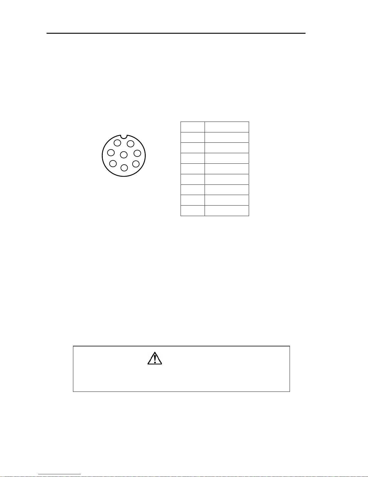
4.8 Setting up option
4.8.1 AIS Interface(Option)
DISP MENU: NAV/AIS
Activate AIS function from DISP/NAV/AIS menu.
Automatic Identification System(AIS) will automatically display ships symbol and data
around your ship. The range of the data display ships can be set from RADAR/AIS
menu.
4.8.2 Remote Display operation
The Processor Unit type MRM-100 can be used as a remote display. To use the
display in this configuration, use the following procedure.
4.8.2.1 Connecting the Remote Display
Connect the Master display (MRM-100) and a Remote display (MRM-100) with the
connecting cable CW-561 (10m) as shown in Figure 4.15.
4.8.2.2 Required set up
Set the RADAR STATUS SELECT MENU setting to INDEPENDENCE/SLAVE, the
display unit will operate with the radar signal supplied from the external radar unit.
Please read "6.9 Operating the Interswitch" on this manual, too.
4.8.2.3 Possible operation on Remote Display
The remote display is configured to be slave to the master display in terms of
transmission control, transmit and standby. Except this function, the remote display
has all controls that the master does, such as, gain, STC, FTC, range scale change,
Pin No. NAME
1 Shield
2 IN-B
3 IN-A
4 OUT-B
5 OUT-A
6 GND
7 AIS ALARM+
8 AIS ALARM-
1
2
3
4
5
6
7
8
Pin assignment on
Data Connector (Top view)
CAUTION:
Do not connect the Antenna unit to the remote display. If do so,
the remote display may malfunction.
Figure 4.19 AIS connector
Page 58

MDC-1840BB/1841BB/1860BB/1810BB/1820BB Series Chapter 4
Operation Manual Installation
0093142122-11 4-25
off-centering, changing mode of operation, VRM, EBL, fixed rings, etc.
In the following circumstances, the display presentation becomes abnormal but is not
fault.
(1) When the transmission is turned off, the slave screen is displayed with plural
coaxial video caused by non-updated video data.
(2) When the master display is set to short range and the remote display to long
range, the remote screen will be shown with coaxial radar picture caused by
higher transmission rate video being supplied from the master display.
(1) On the contrary, when the master display is set to long range and remote display
to short range, the remote display screen will be shown with stretched video
towards range. In a particular case, the radar video display will be shown
halfway due to slower transmission rate.
NOTE: To utilize the nav data, true bearing mode, true motion mode and EPA/ATA
functions in remote display, relevant sensor units such as, gyro compass, speed log
and GPS receiver must be connected.
GYRO / LOG
SCANNER
DATA 1
DATA 2
DATA
AIS
REMOT
GYRO/LOG
SCANNER
DATA 1
DATA 2
DATA
AIS
REMOTE
Master Display
Remote
External Display
Connecting cable
CW-561-10M
(
10m)
Figure 4.20 Remote display connection
Page 59
Chapter 4 MDC-1840BB/1841BB/1860BB/1810BB/1820BB Series
Installation Operation Manual
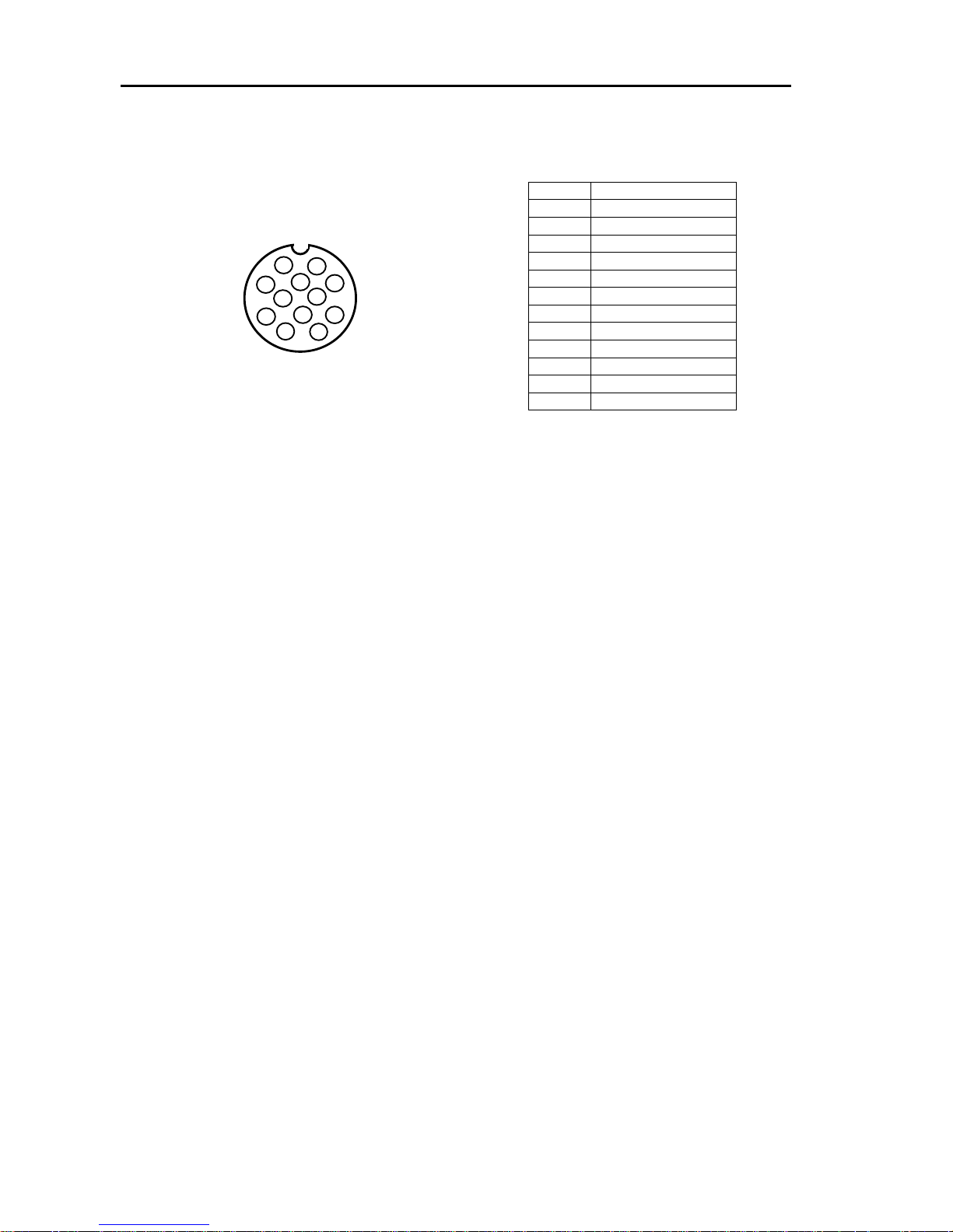
4-26 0093142122-11
Pin No. NAME
1 VIDEO OUT
2 TRIG OUT
3 GND
4 AZIP OUT
5 SHF OUT
6 GND
7 VIDEO IN
8 TRIG IN
9 GND
10 AZIP IN
11 SHF IN
12 +12Vdc(Not used)
1
2
3
4
5
6
7
8
9
12
10
11
Pin assignment on
REMOTEConnector
(Top view)
Figure 4.21 Remote connector
Page 60
MDC-1840BB/1841BB/1860BB/1810BB/1820BB Series Chapter 4
Operation Manual Installation
0093142122-11 4-27
APPENDIX 1
Installation of the ATA module, MRE-300
The ATA module MRE-300 is installed inside the display unit. Use the following the
instructions for installation.
(1) Locate the position of the four fixing studs on the Main Logic PCB (E47-700*)
prepared for the ATA module. (Refer to the figure below)
(2) Put the ATA module (MRE-300) on the studs and press the module gently
downwards in order that the connector installed on the module properly plugs into
the receptacle J705 on the Main Logic PCB.
(3) Fix the module using the four 3 mm fixing screws, prepared in the ATA module kit.
Installation of the AIS module, AIS-100
The AIS module (AIS-100) is installed inside the display unit. Use the following
instructions for installation.
(1) Locate the position of the four fixing studs on the Main Logic PCB (E47-700*)
prepared for the AIS module. (Refer to the figure below)
(2) Put the AIS module (AIS-100) on the studs and press the module gently
downwards in order that the connector installed on the module properly plugs into
the receptacle J716 on the Main Logic PCB.
(3) Fix the module using the four 3 mm fixing screws, prepared in the AIS-100 kit.
Main Logic PCB
E47-700A
J705 J705
J716
MRE-300
AIS-100
Page 61

Chapter 4 MDC-1840BB/1841BB/1860BB/1810BB/1820BB Series
Installation Operation Manual
4-28 0093142122-11
AIS connector pinouts and cable color coding designaltion:
Cable type name Port name Pin number Signal name Color code
CW-387-5M AIS 1 Shield Braid
2 IN-B Red dot/Orange
3 IN-A Black dot/Orange
4 OUT-B Red dot/White
5 OUT-A Black dot/White
6 GND Black dot/Grey
7 AIS ALARM+ Red dot/Pink
8 AIS ALARM- Black dot/Pink
About AIS malfunction alarm
If the AIS transponder gets failed in operation, the AIS ABNORMAL status is supplied
from the transponder to the display causing the error message to appear on the
screen.
NOTE: In case no alarm signal lines are available in the AIS transponder, link the AIS
ALARM+ (Red dot/Pink wire) and AIS ALARM- (Black dot/Pink) signal lines at the
cable end at the transponder side. This processing is necessary to prevent the AIS
alarm message from being shown mistakenly on the display.
Installation of the Gyro Interface module, KSA-08A
The Gyro Interface module (KSA-08A) is installed inside the processor unit. Use the
following instructions for installation.
(1) Dismount the Main Logic PCB E47-700* disconnecting cables connected to
the PCB.
(2) Unscrew the four 3 mm fixing screws on the corner of the Power PCB E47-600*.
The four screws will be used for fixing the Gyro Interface chassis.
(3) Locate the position of the four fixing studs at the corner on the Power PCB
prepared for the KSA-08A module. (Refer to the figure A.2)
(4) Put and fix the KSA-08A module chassis with E47-510A PCB on the studs
using the four 3 mm fixing screws and connect cables to connector J708 on
the backside of the Main Logic PCB. (Refer to the figure A.2)
(5) Fix the Main Logic PCB E47-700* at the position again.
Figure A.1 Position of the ATA and AIS modules to be installed
Page 62

MDC-1840BB/1841BB/1860BB/1810BB/1820BB Series Chapter 4
Operation Manual Installation
0093142122-11 4-29
(6) Reconnect the cables to the connectors J707 and J718 on the topside of the
Main Logic PCB. (Refer to the figure A.2)
(3) Reconnect all cables to the Main Logic PCB.
Cable connecting list
No. KSA-08A (E47-510A) Main Logic PCB (E47-700*)
1 J512 J708
2 J515 J707
3 J517/518 J718
GYRO connector pinouts and cable color coding designaltion:
Cable type name Port name Pin No. Signal name Color code
CW-388-5M GYRO 1 S1 Red dot/Orange
2 S2 Black dot/Orange
3 S3 Red dot/Grey
4 R1 Red dot/White
5 R2 Black dot/White
6 COM Red dot/Yellow
7 GND Shield
8 LOG1 Red dot/Pink
9 LOG2 Black dot/Pink
10 NC
Page 63

Chapter 4 MDC-1840BB/1841BB/1860BB/1810BB/1820BB Series
Installation Operation Manual
4-30 0093142122-11
Figure A.2 Fitting ATA, AIS and Gyro Interface modules into Main Logic PCB
ATA MRE-300 PCB module
(E35-703*)
Main Logic PCB (E47-700B)
AIS-100 PCB module (E47-720*)
Main cabinet chassis
KSA-08A PCB module
(E47-510*)
J515
J517/J518
J512
J718
J708
J707
Page 64

MDC-1840BB/1841BB/1860BB/1810BB/1820BB Series Chapter 4
Operation Manual Installation
0093142122-11 4-31
APPENDIX 2
Optional cables pinouts and cable color-coding designation
DATA connector pinouts and cable color coding designaltion:
Cable type name Port name Pin No. Signal name Color code
CW-376-5M DATA 1 Shield Shield, Blue
2 OUT-A White
3 OUT-B Red
4 IN-A Orange
5 IN-B Black
6 GND Green
REMOTE connector pinouts and cable color coding designaltion:
Cable type name Port name Pin No. Signal name Color code
CW-561-10M REMOTE 1 VIDEO OUT Coax. Black 1D(*)/White
2 TRIG OUT Coax. Black 2D(*)/White
3 GND Coax. Shield
4 AZIP OUT White
5 AHF OUT Yellow
6 GND Coax. Shiled
7 VIDEO IN Coax. Black 3D(*)/White
8 TRIG IN Coax. Black 4D(*)/White
9 GND Shield
10 AZIP IN Green
11 SHF IN Blue
12 +12V DC NC
NOTE for (*):
1D – 4D: This notation indicates the number of dots printed on the cable jacket.
Page 65

Chapter 4 MDC-1840BB/1841BB/1860BB/1810BB/1820BB Series
Installation Operation Manual
4-32 0093142122-11
APPENDIX 3
Recommended TFT Display
Manufacturer
InnoScan Industrial
Computer A/S
(Denmark)
AYDIN Displays Inc.
(USA)
CONRAC GmbH
(Germany)
Type name MON1900M 4218R3C-341-51L 6017SD
Screen size (inch) 19.0 18.1 17
Number of dots 1280 x 1024 1280 x 1024 1280 x 1024
Dot pitch (mm) 0.28 x 0.28 0.28 x 0.28 0.264 x 0.264
Effective diameter (mm) 268.8 268.8 253.44
Contrast ratio Not specified Not specified 500:1
Light intensity (cd/m2) 250 (typ) 200 (typ) 200 (typ)
Viewable angle (deg) +/-80 +/-85 +/-85
Input signal Analog RGB Analog RGB Analog RGB
Power supply 10-36 VDC (option) 21-32 VDC 24 VDC
Appliable technical std.
IEC 60945 Ed.3 Yes Yes Yes
IEC 60936-1 Yes (BSH) No Yes
Manufacturer Jakob Hatterland Display AS (Norway)
Type name JH17T01MMDA2 JH18T01MMDA2 JH19T01MMDA2
Screen size (inch) 17.4 18.1 19.0
Number of dots 1280 x 102 4 1280 x 1024 1280 x 1024
Dot pitch (mm) 0.27 x 0.27 0.2805 x 0.2805 0.294 x 0.294
Effective diameter (mm) 259.2 269.28 282.24
Contrast ratio 400:1 300:1 500:1
Light intensity (cd/m2) 220 max. 200 (typ) 250 (typ)
Viewable angle (deg) +/-80 +/-85 +/-85
Input signal Analog RGB Analog RGB Analog RGB
Power supply 24 VDC 24 VDC 24 VDC
Appliable technical std.
IEC 60945 Ed.3 Yes Yes Y es
IEC 60936-1 No No No
Page 66

MDC-1840BB/1841BB/1860BB/1810BB/1820BB Series Chapter 4
Operation Manual Installation
0093142122-11 4-33
Manufacturer
CONRAC GmbH
(Germany)
KENT MODULAR ELECTRONICS LTD
(UK)
Type name 6019SD 29LR183D45UN 29LR193D35MP
Screen size (inch) 19.0 18.1 19.0
Number of dots 1280 x 1024 1280 x 1024 1280 x 1024
Dot pitch (mm) 0.294 x 0.294 0.2805 x 0.2805 0.294 x 0.294
Effective diameter
(mm)
282.44 269.28 282.24
Contrast ratio 500:1 350:1 500:1
Light intensity (cd/m2) 200 (typical) 200 (typical) 250 (typical)
Viewable angle (deg) +/-85 +/-85 +/-85
Input signal Analog RGB Analog RGB Analog RGB
Power supply 24 VDC 15 – 30 VDC 15 – 30 VDC
Appliable technical std.
IEC 60945 Ed.3 Yes Yes Yes
IEC 60936-1 Yes No No
Page 67

MDC-1840BB/1841BB/1860BB/1810BB/1820BB Series Chapter 5
Operation Manual BASIC OPERATION
93142122-07 Contents
Chapter 5
Basic Operation
Contents
Page No.
5.1 Introduction............................................................................. 5-1
5.2 Control Panel Layout ............................................................. 5-1
5.3 Operating Controls.................................................................5-1
5.4 Getting Started........................................................................ 5-7
5.5 Basic Radar Operations.........................................................5-8
5.5.1 Range scale selection .......................................................................5-8
5.5.2 Transmission Pulse selection............................................................5-8
5.5.3 Gain control.....................................................................................5-10
5.5.4 Anti-clutter SEA control ...................................................................5-10
5.5.5 Anti-clutter RAIN control..................................................................5-11
5.5.6 Bearing measurement using a single EBL....................................... 5-11
5.5.7 Bearing measurement using two EBLs ........................................... 5-11
5.5.8 Range measurement using Range Rings........................................5-12
5.5.9 Range measurement using VRM ....................................................5-12
5.5.10 Range measurement with two VRMs ..............................................5-12
5.5.11 Measuring the distance and bearing between any two points
by offset 1st EBL/1st VRM...............................................................5-12
5.5.12 Picture off-centering ........................................................................5-13
5.5.13 Selection of presentation mode.......................................................5-13
5.5.14 Setting the Guard Zone ...................................................................5-15
5.5.15 Control panel brilliance....................................................................5-16
5.5.16 Displaying the navigational data......................................................5-16
APPENDIX 1 Interpretation of Radar Images ..............................5-18
APPENDIX 2 Receiving the Radar Beacons and SARTs............5-22
Page 68

MDC-1840BB/1841BB/1860BB/1810BB/1820BB Series Chapter 5
Operation Manual Basic Operation
0093142122-10 5-1
Chapter 5 Basic Operation
5.1 Introduction
In this chapter, all necessary operating instructions are given from getting started to
turning off the system. The following panel layout illustration will give you an idea what
sort of key switches and controls are available as well as their brief functional
descriptions.
5.2 Control Panel Layout
The following illustration shows the layout of the control panel. All controls and key
switches are grouped for respective functions.
Figure 5.1 Control panel layout
5.3 Operating Controls
All necessary radar controls and functional settings can be made on the display
control panel. For fundamental radar operations, such as turning on and off the radar,
transmit, range change, gain control, anti-clutter rain and sea controls, the respective
dedicated controls and key switches are provided, which are grouped on the left side
of the control panel. For setting up various functions and ATA operations, relevant key
switches and the Joystick are provided on the right side of the control panel.
Basic Radar Controls
RADAR and CAL MENU keys
Radar Control Keys
Menu Selection Keys
Joystick
Page 69

Chapter 5 MDC-1840BB/1841BB/1860BB/1810BB/1820BB Series
Basic Operation Operation Manual
5-2 0093142122-10
SWITCHES AND CONTROLS
POWER switch
STBY/TX switch
RANGE +/- switches
SP/LP switch
BRILL control
ON
OFF
POWER
STBY
TX
PULSE
RANGE
+
SP
LP
PULSE
BRILL
The POWER key switch turns on and off the mains supply to the
radar system.
When the system goes into standby mode after 3 minutes
preheating period, the STBY/TX key switch functions as a
transmission switch. To temporarily stop the transmission, press the
STBY/TX key again. The system returns to standby mode.
The RANGE key changes the range scale. A press of the + key or –
key increases or decreases the range scale, respectively.
The SP/LP key is used to change the transmission pulse length to
either long or short. Default is a standard pulse length. Subsequent
pressing of the key toggles the pulse length between standard and
long pulses.
The BRILL control is used to set the brilliance of the display tube.
Turning the control CW increases the picture brilliance and CCW
decreases the brilliance.
Page 70

MDC-1840BB/1841BB/1860BB/1810BB/1820BB Series Chapter 5
Operation Manual Basic Operation
0093142122-10 5-3
GAIN control
SEA control
RAIN control
EBL ON/OFF key
GAIN
SEA
RAIN
SEL
EBL
The GAIN control is used to vary the receiver gain. Turning the GAIN
control CW increases the receiver gain, and CCW decreases the
gain. Select AUTO1, AUTO2, or HARBOR by ADJUST/ADJUST
MENU, the automatic gain control will come into effect. The GAIN
MANUAL sign will change to GAIN AUTO on the screen. In this
mode, no manual control is available.
The SEA control is used to reduce the clutter echo returned from the
sea surface. Turning the control CW reduces the clutter and its effect
becomes the largest at a full CW position and minimum at a full
CCW position. Select AUTO1, AUTO2, or HARBOR by
ADJUST/ADJUST MENU, Harbor STC and the Automatic STC
functions will come into effect. The HARBOR STC that provides a
preset Anti-clutter sea effect, optimized for narrow areas. The
AUTO1 and AUTO2 STC provides a hands-free Anti-clutter sea
effect. The mode will display as AUTO1, AUTO2, HARBOR and SEA
MANUAL in sequence. In the HARBOR and Auto Anti-clutter Sea
modes, the manual control is disabled.
The RAIN control is used to reduce the clutter echo from rain or snow.
Turning the control CW reduces the clutter echo with maximum effect
at a full CW position and minimum at a full CCW position. Select
AUTO1 or AUTO2 by ADJUST/ADJUST MENU, the automatic
anti-rain clutter control will come into effect. The RAIN MANUAL sign
will change from RAIN to RAIN AUTO on the screen. In this mode, the
manual control is disabled.
The EBL SEL key is used to switch EBL control at every press of the
key. When the second EBL and Parallel Index Line (PI) feature are
selected, this key is used to select these markers in the following
cyclic order.
- First press: First EBL
- Second press: Second EBL
- Third press: Parallel Cursor
- Subsequent press of the key repeats the
above steps.
Page 71

Chapter 5 MDC-1840BB/1841BB/1860BB/1810BB/1820BB Series
Basic Operation Operation Manual
5-4 0093142122-10
EBL control
VRM SEL key
VRM control
PANEL key
SEL
PANEL
EBL
VRM
To select the second EBL, press MENU key and select 2nd EBL
item from the DISP/MARK menu. Then press ENT key and select
ON. To erase the second EBL, select OFF from the menu. To select
the Parallel Index line, select PI from the same menu and select
ON.
The EBL control is a rotary type control used to move the EBL
position and parallel Index line.
The VRM SEL key is used to switch VRM control at every press of
the key. When the second VRM and Parallel Index Line (PI) feature
are ON, this key is used to select these markers in the following
cyclic order.
- First press: 1st VRM
- Second press: 2nd VRM
- Third press: Parallel Cursor
- Subsequent press of the key repeats the above
steps.
To select the second VRM, press MENU key and select 2nd VRM
from the DISP/MARK menu. Then press ENT key and select ON.
To erase the second VRM, select OFF from the menu.
To select the Parallel Index line, select PI from the same menu and
select ON.
The VRM control is a rotary type used to move the VRM position.
The PANEL key is used to change the brilliance of the panel
illumination. Every press of the key will increase or decrease the
brilliance in sequential order. The illumination level will be set to an
appropriate level when the radar is first turned on.
Page 72
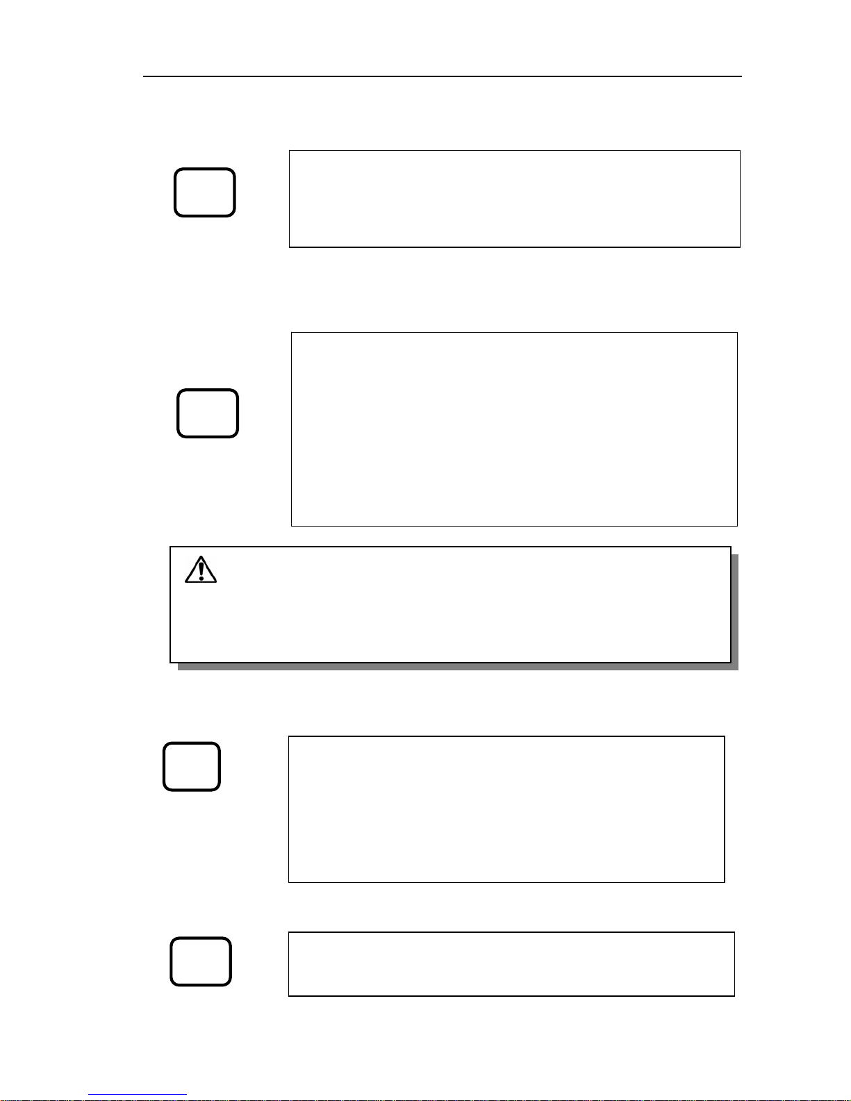
MDC-1840BB/1841BB/1860BB/1810BB/1820BB Series Chapter 5
Operation Manual Basic Operation
0093142122-10 5-5
OFFCENTER key
DATA DISP .key
MODE key
OFFSET key
OFF
CENTER
Caution: The navigation data shown in this step is directly received from
external navigator equipment. Note that the COG (Course Over Ground) and the
SOG (Speed Over Ground) data supplied from the navigator device may slightly differ
from what is shown in the top right corner of the screen as own ship’s bearing and
speed data.
DATA
DISP
MODE
OFFSET
The OFFCENTER key is used to offset the picture to an assigned
point determined by the cross cursor. First, move the cross cursor
with Joystick to the point where the picture is to be offset. Second,
press the OFF CENTER key. A further press of the key will reset the
picture to the screen center.
The DATA DISP key is used to show navigational information on
the upper right of the screen. Every press of the key displays the
following information in sequence.
First press: Own ship’s course and speed data
Second press: Own ship’s position obtained from LORAN
Receiver.
Third press: Own ship’s position obtained from (D) GPS in
lat/long coordinate.
Fourth press: Own ship’s position and the distance/bearing
to a waypoint en route.
The MODE key is used to change the picture mode. Every press
of the key will change the mode in the following sequence.
First press: H UP RM (Head Up, Relative Motion)
Second press: N UP RM (North Up, Relative Motion)
Third press: C UP RM (Course Up, Relative Motion)
Fourth press: N UP TM (North Up, True Motion)
Further press of the key returns the picture mode to the H UP RM
mode.
The OFFSET key is used to set the EBL 1 and VRM 1 off-centered
on the screen. Every press of the key toggles the EBL 1 and VRM 1
off-centered and centered.
Page 73

Chapter 5 MDC-1840BB/1841BB/1860BB/1810BB/1820BB Series
Basic Operation Operation Manual
5-6 0093142122-10
UPDATE key
DELETE key
ACQ key
TARGET
TARGET key
TRUE/REL key
ALARM (GZ) key
HL OFF
UPDATE
DELETE
ACQ
TARGET
VECT
TRUE/REL
ALARM
(GZ)
The UPDATE key is used in the EPA function, in conjunction with
the TARGET key and Joystick, to correct a plotted target position.
For detail, refer to Para 6.6.11 “Correcting the latest plotting
position”.
The DELETE key is used in the EPA/ATA function, in conjunction
with the TARGET key, to cancel a plotted target. For detail, refer to
Para 6.6.1 Operation of EPA or Para 6.7.1 Using ATA.
The ACQ key is used in the EPA/ATA function, in conjunction with
the TARGET key, to acquire a target for tracking. For detail, refer
to Para. 6.6.1 Operation of EP
A
or Para. 6.7.1 Using ATA.
The TARGET key is used in the EPA/ATA function, to assign the
target number to acquire, delete or display the ATA/EPA information
of each tracked target. For detail, refer to Para 6.6.1 Operation of
EPA or Para 6.7.1 Using ATA.
The TRUE/REL key is used to change EPA or ATA target vectors to
Relative or True.
The ALARM key is used to turn on and off the Guard Zone Alarm.
Page 74

MDC-1840BB/1841BB/1860BB/1810BB/1820BB Series Chapter 5
Operation Manual Basic Operation
0093142122-10 5-7
HL OFF Key
AUDIO OFF
MENU key
ENT key
5.4 Getting Started
(1) Press the POWER ON/OFF key switch. The red LED lamp lights accordingly and
a 3-minute timer starts to count down. At the same time, the following
information will be shown on the screen.
z Application software name
z Range scale
z Range ring interval
(2) When the countdown timer finishes, the STANDBY sign will appear on the
screen.
HL OFF
AUDIO
OFF
MENU
ENT
The HL OFF key is used to momentarily remove the Heading Line
from the screen. When the key is pressed and held, the Heading
Line will be removed and, when released it appears again.
The AUDIO OFF key is used to temporarily turn off the audio alarm.
A press of the key will silence the alarm.
The MENU key is used to display the MENU on the screen. Every
press of the key will change the contents of the menu as follows:
First press: RADAR MENU. This menu contains all the preset
items for radar functions, sensor data display and
EPA/ATA operational settings.
Second press: CAL MENU. This menu contains all technical
settings for the radar operation and Performance
Monitor.
The ENT key is used to activate and fix the selected menu items by
the joystick.
Page 75

Chapter 5 MDC-1840BB/1841BB/1860BB/1810BB/1820BB Series
Basic Operation Operation Manual
5-8 0093142122-10
(3) Press the STBY/TX key to transmit. The radar starts transmission and the radar
video, alphanumeric and graphic information will be shown on the screen at a
preset brilliance level. Refer to Figure 5.2 for possible screen presentation.
5.5 Basic Radar Operations
Basic radar controls can be set up using dedicated keys and controls on the control
panel. These include:
z Range scale selection
z Pulse selection
z Gain control
z Anti-clutter SEA
z Anti-clutter RAIN
z Bearing measurement with EBL and two EBLs
z Range measurement with VRM and two VRMs
z Picture off-centering
z Selection of presentation mode
z Guard Zone Alarm
z Control panel brilliance
All available screen presentations are shown in Figure 5.2 and respective meanings
are given under the illustration.
5.5.1 Range scale selection
A press of the RANGE + or RANGE – key will increase or decrease the range scale by
step.
5.5.2 Transmission Pulse selection
Press the SP/LP key if required, to change the pulse length according to your
requirement. The pulse change function is available on specific range scales, ranging
from 3/4 NM to 12 NM. A vailable pulse lengths vs range scales are shown in Table 5.1
“Range vs Transmission Pulse Length”.
Page 76

MDC-1840BB/1841BB/1860BB/1810BB/1820BB Series Chapter 5
Operation Manual Basic Operation
0093142122-10 5-9
No. Descriptions
11 VRM (No.1/No.2) distance data
12 Parallel Index Line interval
13 Parallel Index Line bearing
14 EBL (No.1/No.2) bearing data
15 TX Frequency Band display
16 Electronic Buzzer status
17 Picture Enhancement status (ON)
18 Interference Rejection status
19 TX Pulse length status
20 Picture mode status
21 Range scale and Rings interval
dis
play
No. Descriptions
1 Tuning bar graph & tuning mode display
2 Screen & EBL/VRM offsets display
3 Guard zone position (Range/Bearing)
4 Trail length in time
5 Bearing/Speed Data & signal source
names
6 Tidal data & track mode
7 Own ship’s data & sensor name
8 Ship’s and Waypoint position data with
position sensor name
9 Cross cursor position data (lat/long or
Range/Bearing)
10 EPA (ATA) data
Figure 5.2 MDC-1800B series On-screen information
12 NM
090
HDG 045.2゜
054.9゜
SOG 20
.
4KT
MAN DRIFT
20
.
3KT
SET
083
.
6゜
VRM
TRUE
PI
115.0゜
PI
0.025NM
EBL
>230.0゜
263.0゜
>0.053NM
0.093NM
TRUE
2NM
H
UP
RM(R)
TUNE AUTO
GAIN
SEA
RAIN
MAN
AUTO
AUTO
COG
LAT
LON
RNG
T BRG
WP RT01 DGPS
LAT
LON
R02
.
345 NM
CURSOR
TARGET
XTE
AGE
CPA
TCPA
COG
T BRG
RNG
SOG
3
.
0 MIN
2
.
6NM
5
.
3 MIN
126
.
8゜
21
.
7KT
338
.
4゜
13
.
7NM
VECT 3 MIN
BRG 090
.
0°
ID
TARGET ID
COG
SOG
21
.
7KT
CPA
TCPA
4
.
3NM
12
.
6 MIN
100
110
120
130
140
150
160
170
080
070
060
050
040
030
020
010
270
260
250
240
230
220
210
280
290
300
310
190
200
320
330
340
350
000
180
MAN
LIM CPA
TCPA
0
.
5NM
5
.
3 MIN
EPA DATA
338.0゜
338
.
0゜
13
.
7NM
X-BAND
LP
IR1
ENH
TRAILS
12 MIN
O
FFSET
BZ OFF
O
FF SENT
PM
02
01
UNRELIABLE
12
MM SI 431023652
PLOT DATA
AIS DATA
DISP LIM 3
.
0NM
POSITION
NO VALID SENSOR
RADAR DISP
ADJUST
SYSTEM
GYRO
GND
STAB
35゜38
.
632N
139゜06
.
352E
SPD
20
.
4KTLOG
STAB
MAN
TRUE
OWN SHIP DGPS
LAT
LON
35゜38
.
632N
139゜06
.
352E
35゜38
.
632N
139゜06
.
352E
RADAR
DEPTH
TEMP
156
.
4M
13
.
4℃
DISP
ADJUST SYSTEM
WIDTH 090.0°
RNG 9
.
0NM
DEPTH 3
.
2NM
ALARM
AIS ON
MAP N
o
1
VAV ALIGN
OS PAST POSN
HDG
045
.
2゜
054.9゜
SOG 20
.
4KT
MAN DRIFT
20
.
3KT
SET
083
.
6゜
COG
LAT
LON
RNG
T BRG
WP RT01 DGPS
LAT
LON
R02
.
345 NM
CURSOR
TARGET
XTE
CPA
TCPA
COG
T BRG
RNG
SOG
2
.
6NM
5
.
3 MIN
126
.
8゜
21
.
7KT
338
.
4゜
13
.
7NM
VECT 3 MIN
ID
TARGET ID
COG
SOG
21
.
7KT
CPA
TCPA
4
.
3NM
12
.
6 MIN
MAN
LIM CPA
TCPA
0
.
5NM
5
.
3 MIN
ATA DATA
338
.
0゜
338
.
0゜
13
.
7NM
02
01
UNRELIABLE
MMSI 431023652
PLOT DATA
AIS DATA
DISP LIM 3
.
0NM
POSITION
NO VALID SENSOR
GYRO
GND
35゜38.632N
139゜06
.
352E
SPD
20
.
4KTLOG
MAN
TRUE
OWN SHIP DGPS
LAT
LON
35゜38
.
632N
139゜06
.
352E
35゜38
.
632N
139゜06
.
352E
DEPTH
TEMP
156
.
4M
13
.
4℃
STAB
STAB
2
3
7
8
9
10
11
12
13
14
15
16
17
18
19
20
21
4
6
5
1
Page 77

Chapter 5 MDC-1840BB/1841BB/1860BB/1810BB/1820BB Series
Basic Operation Operation Manual
5-10 0093142122-10
Table 5.1 Range vs Transmission Pulse Length(PL)
RANGE(NM) Pulse code Pulse Length
(4kW)
Pulse Length
(6/12kW)
Pulse Length
(25kW)
0.125 SP 0.08 us 0.08 us 0.08 us
0.25 SP 0.08 us 0.08 us 0.08 us
0.5 SP 0.08 us 0.08 us 0.08 us
SP 0.08 us 0.08 us 0.08 us 0.75
M1P 0.25 us 0.25 us 0.3 us
SP 0.08 us 0.08 us 0.08 us 1.5
M1P 0.25 us 0.25 us 0.3 us
M1P 0.25 us 0.25 us 0.3 us 3
M2P 0.8 us 0.5 us 0.6 us
M1P 0.25 us 0.25 us 0.3 us 6
M2P 0.8 us 0.5 us 0.6 us
M2P 0.25 us 0.5 us 0.6 us 12
LP 0.8 us 1.0 us 1.2 us
24 LP 0.8 us 1.0 us 1.2 us
48(4KW) LP 0.8 us 1.0 us 1.2 us
64 (6KW) LP - 1.0 us 1.2 us
72 (12KW) LP - 1.0 us 1.2 us
96 (25KW) LP - - 1.2 us
5.5.3 Gain control
The GAIN control is used to change the receiver gain. The gain control can be
switched to manual or auto mode by ADJUST/ADJUST MENU. When the equipment
is turned on at first, the gain control will be defaulted to manual mode.
Set the gain control as appropriate to your operational needs. As a standard setting,
turn the GAIN control clockwise to 3/4 of the full excursion. This provides slight noise
speckles on the mid ranges and adequate speckles on the long ranges.
To set the auto gain mode, select AUTO1, AUTO2, or HARBOR by ADJUST/ADJUST
MENU. The receiver gain will be automatically set and the manual gain control will
accordingly become inactive.
5.5.4 Anti-clutter SEA control
The Anti-clutter SEA control is used to reduce the clutter echo appearing around the
center of the screen, which is caused by the echo return from the sea surface. The
effect of the control is highest at the center of the screen and reduces with distance.
Page 78

MDC-1840BB/1841BB/1860BB/1810BB/1820BB Series Chapter 5
Operation Manual Basic Operation
0093142122-10 5-11
The Anti-clutter SEA control is effective up to approximately 6 NM, which can be
switched to either manual or auto mode by ADJUST/ADJUST MENU. When first
turned on, the anti-clutter sea control is defaulted to manual mode. To set the auto
Anti-clutter mode, select AUTO1, AUTO2, or HARBOR by ADJUST/ADJUST MENU.
The receiver gain will be automatically set and the manual SEA clutter control will
accordingly become inactive. The HARBOR STC provides a preset Anti-clutter sea
effect, optimized for narrow areas. The AUTO1 and AUTO2 STC provides a
hands-free Anti-clutter sea effect. The mode will display as AUTO1, AUTO2, HARBOR,
and MANUAL. In HARBOR and Auto Anti-clutter Sea modes, the manual control is set
ineffective.
5.5.5 Anti-clutter RAIN control
The RAIN control is used to reduce the clutter echo appearing on the screen caused
by the rain or snow. The effect of the anti-clutter rain control increases as you turn the
control clockwise and is the greatest at a fully clockwise position. The anti-clutter
RAIN control can be switched to either a manual or auto mode by ADJUST/ADJUST
MENU.
When first turned on, the anti-clutter RAIN function is defaulted to manual mode. To
set the auto RAIN-clutter control, select AUTO1 or AUTO2 by ADJUST/ADJUST
MENU. The clutter echo from rain or snow will be reduced automatically and the
manual rain clutter control will become inactive.
5.5.6 Bearing measurement using a single EBL
(1) Activate the 1st EBL from the DISP/MARK menu with select ON. The EBL will be
displayed in a dashed line with the bearing display in the bottom left of the
screen. An arrow mark will be shown on the front of the digital display to indicate
the EBL is active.
(2) Select the bearing mode if necessary, either RELATIVE or TRUE by DISP/[BRG
TRUE/REL] MENU.
(3) Rotate the EBL control to measure the bearing of a target. To measure a single
target, always set the EBL on the center of the target. To measure the bearing of
the edge of a landmass, move EBL towards the inside of the landmass by half of
the aerial horizontal beam width.
(4) To erase the EBL, select OFF from the DISP/MARK/1st EBL menu item.
5.5.7 Bearing measurement using two EBLs
(1) Activate the 2nd EBL from the DISP/MARK menu with select ON. The 2nd EBL will
be shown with the 1st EBL in a dotted line with the bearing display underneath the
Page 79

Chapter 5 MDC-1840BB/1841BB/1860BB/1810BB/1820BB Series
Basic Operation Operation Manual
5-12 0093142122-10
1st EBL bearing display. An arrow mark will be shown on the front of the digital
display to indicate the selected EBL is active.
(2) Use the same step as step (2) and (3) in the 1st EBL operation.
(3) To switch the active EBL to another, press the EBL SEL key.
(4) To erase the second EBL, select OFF from the DISP/MARK/2nd EBL menu item.
5.5.8 Range measurement using Range Rings
Display the RANGE RINGS on the screen from the DISP/MARK menu with select ON.
The range ring's interval is indicated on the top left corner of the screen under the
range indication. Approximate target range can be estimate with range rings.
5.5.9 Range measurement using VRM
(1) Activate the 1st VRM from the DISP/MARK menu with select ON to show VRM on
the screen. The VRM will be shown in a dashed line with the distance displayed in
the bottom right of the screen. An arrow mark will be shown in front of the digital
display indicating that VRM is active.
(2) Rotate the VRM control to measure the distance to a target. Always place the
VRM on the right front of the target.
(3) To erase the VRM, select OFF from the DISP/MARK/1st VRM menu item.
5.5.10 Range measurement with two VRMs
(1) Activate the 2nd VRM from the DISP/MARK menu with select ON. The 2nd VRM
will be shown with 1st VRM, in a dotted line with the distance displayed shown
underneath the 1st VRM display. An arrow mark will be shown on the front of the
digital display to indicate which VRM is active to control.
(2) Rotate the VRM control to measure the distance to a target. Always place the
VRM on the right front of the target.
(3) To switch the active VRM to another, press the VRM SEL key.
(4) T o erase the second VRM, select OFF from the DISP/MARK/2nd VRM menu item.
5.5.11 Measuring the distance and bearing between any two points by offset 1st
EBL / 1st VRM
(1) Activate the 1st EBL and 1st VRM from the DISP/MARK menu with select ON to
display 1st EBL and 1st VRM.
(2) Place the cross cursor on the first target.
(3) Press the OFFSET key. The origin of 1st EBL / 1st VRM is now set on the first
target.
(4) Move 1st EBL to fall in the center of the second target.
Page 80

MDC-1840BB/1841BB/1860BB/1810BB/1820BB Series Chapter 5
Operation Manual Basic Operation
0093142122-10 5-13
(5) Move 1st VRM to touch the right front of the second target. The distance between
the two targets will be shown on the bottom right center of the screen.
Figure 5.3 Measuring the distance between two points
5.5.12 Picture off-centering
The radar picture can be offset to any position within 2/3 of the screen radius. Use the
following procedure.
(1) Move the cross cursor to a desired point to be offset.
(2) Press the OFF CENTER key. The entire radar picture will be moved to the
specified point.
(3) A further press of the key will reset the picture to the center position.
5.5.13 Selection of presentation mode
The following four kinds of presentation modes are available.
(1) Head Up, Relative Motion
(2) North Up, Relative Motion (Note: Bearing information must be provided)
(3) Course Up, Relative Motion (Note: Bearing information must be provided)
(4) True Motion (Note: The bearing and speed information must be provided)
To select the presentation mode, press the MODE key. Every press of the key will
change the presentation mode in the above sequence.
Target 1
Target 2
EBL REL
20.0
o
VRM
3.00
Target 1
Target 2
NM
CURSOR REL
110.0
o
2.000 NM
The cursor position
data is shown here
1st EBL
1st VRM
1st VRM
1st EBL
Page 81

Chapter 5 MDC-1840BB/1841BB/1860BB/1810BB/1820BB Series
Basic Operation Operation Manual
5-14 0093142122-10
000.0 TRUE
045.0 TRUE
Head Up, Relative Motion (H UP RM)
Ship’s position and heading line are always
fixed to the screen center and 0 degree of the
bearing scale, respectively. Bearings of the
objects displayed on the screen are relative to
ship’s heading. When own ship changes her
course, all displayed objects will move in
azimuth, accordingly. (Bearing Un-stabilized)
True Motion (N UP TM)
Own ship and each target moves with its true
motion on the radar screen. When own ship
reaches 2/3 of the screen radius, it is reset
backwards to a specified point to repeat the
display. To achieve the True Motion display, a
bearing sensor and a speed sensor must be
connected to the radar system to provide true
bearing and true speed information.
000.0 REL
North Up, Relative Motion (N UP RM)
Own ship’s position is fixed to the center of the
screen, meanwhile, the azimuth bearing scale
is stabilized in which true north refers to the
cursor scale of 000.0 degree. When own ship
changes her course, all displayed objects will
stay stationary in azimuth, accordingly.
(Bearing stabilized) To allow the bearing to be
stabilized, the true bearing data must be
provided from a bearing sensor such as a
gyrocompass.
Course Up, Relative Motion (C UP RM)
The picture mode is the same as the North Up,
Relative Motion mode except, the ship’s
intended course pointed by the ship’s heading
line is brought to top of the display.
045.0 TRUE
000.0 TRUE
Page 82
MDC-1840BB/1841BB/1860BB/1810BB/1820BB Series Chapter 5
Operation Manual Basic Operation
0093142122-10 5-15
5.5.14 Setting the Guard Zone
The Guard Zone Alarm warns the operator a target has entered the preset alarm zone.
When the target stays in the zone for more than 8 seconds, the ALARM sign will flicker
and an audio alarm sounds. Press the AUDIO OFF key to silence the alarm.
To set up the position of the Guard Zone.
(1) Press the ALARM (GZ) key . This allows the EBL and VRM controls to be used for
moving the Alarm Zone in azimuth and range, respectively.
(2) Move the EBL control to set the position of the Guard Zone in azimuth. The
center bearing of the Guard Zone will be displayed in the lower right corner of
the screen.
(3) Move the VRM control to set the position of the Guard Zone in range. The
distance of the outer edge of the Guard Zone will be displayed in the same place
as the bearing display. The minimum distance is limited to 0.6 NM.
To set up the depth and width of the Guard Zone
(Reference drawing: Figure 5.4 The outline of the Guard Zone Alarm)
(4) Press the EBL SEL key and rotate the EBL control to set up the width of the
alarm zone. An arrow mark will be shown on the front of the WIDTH to indicate
width is active to control. A further press of the key will return to control the Guard
Zone in azimuth.
(5) Press and hold the VRM SEL key and rotate the VRM control to set up the depth
of the alarm zone. An arrow mark will be shown on the front of the DEPTH to
indicate depth is active to control. A further press of the key will return to control
the Guard Zone in range. The minimum distance of the inner zone to own ship is
limited to 0.5 NM.
(6) Press the ENT key to fix the settings. The Guard Zone will be shown on the
screen.
CAUTION: In the following case, the alarm function will become inoperative. The
ALARM range and bearing displays accordingly flicker to notify that the function is
inoperative.
(1) When the alarm zone is set in the vicinity of the screen center.
(2) When the alarm zone is set beyond the viewable screen area caused by
improper range scale setting such as, the range scale is too short,
off-centering is too much, etc.
Page 83
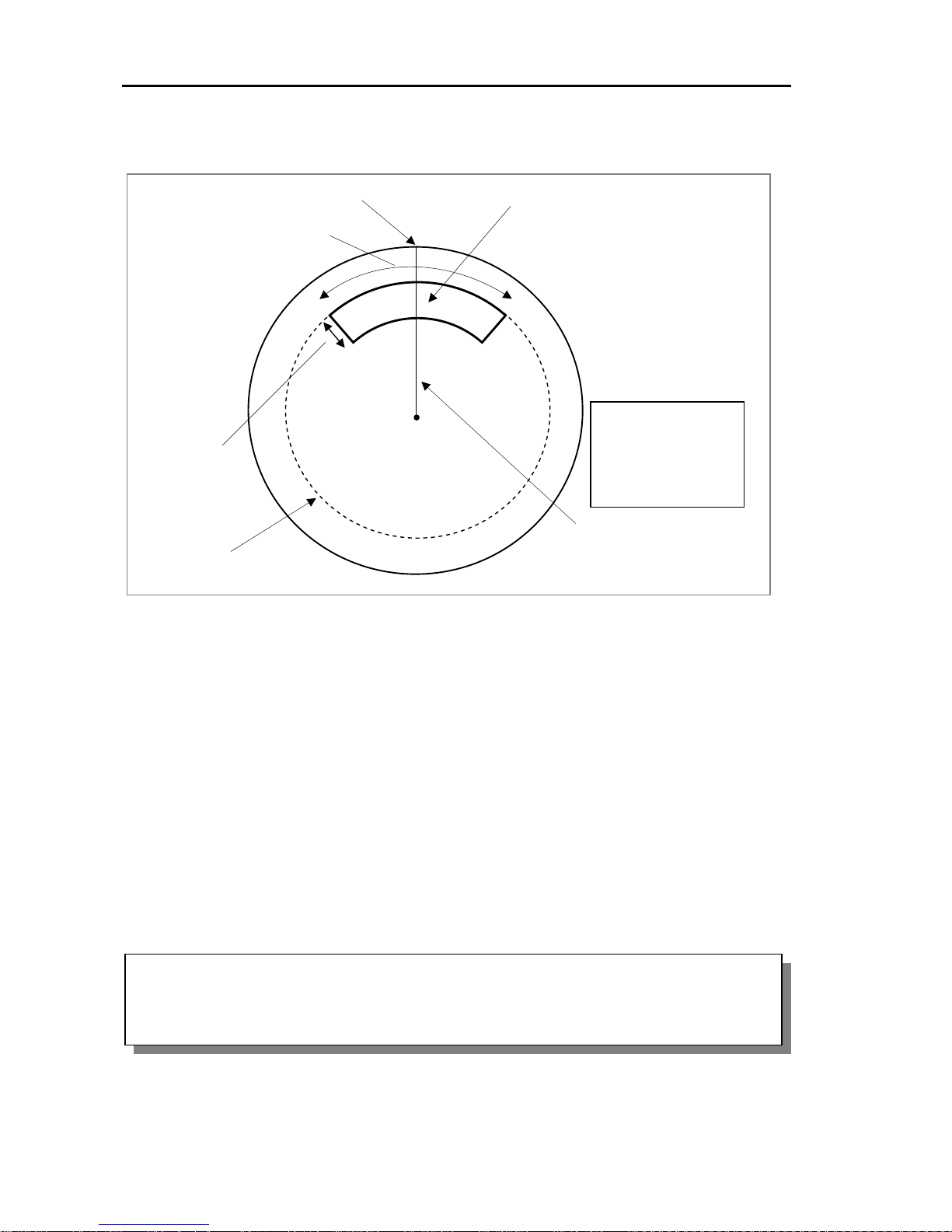
Chapter 5 MDC-1840BB/1841BB/1860BB/1810BB/1820BB Series
Basic Operation Operation Manual
5-16 0093142122-10
5.5.15 Control panel brilliance
The control panel illumination is set by default. To change the brilliance, use either the
following procedure.
(1) Keep pressing the PANEL key to change the panel illumination in 10 cyclic steps,
starting from OFF, increasing, decreasing and finally to OFF again.
5.5.16 Displaying the navigational data
Navigational data such as own ship’s position, waypoint position and the distance and
bearing to a waypoint can be shown on the screen. Press the DATA DISP key to
display this data on the screen.
Each press of the DATA DISP key changes the contents of the navigation display in
the following sequence.
NOTE:
1. A navigator unit must be connected to the display unit.
2. The serial data format must be selected. Refer to Para 6.3 “SYSTEM: I/O SETUP
MENU” for detail.
Figure 5.4 The outline of the Guard Zone Alarm
ALARM
>BRG 000.0
o
WIDTH 000.0
o
>RNG 0.500NM
DEPTH 0.100NM
Guard Zone
EBL for setting the Guard
Zone bearing
VRM for setting the
Guard Zone range
The Guard Zone
depth
Bearing of Guard Zone
The Guard Zone width
Page 84

MDC-1840BB/1841BB/1860BB/1810BB/1820BB Series Chapter 5
Operation Manual Basic Operation
0093142122-10 5-17
OFF: The navigation display is turned off.
OWN SHIP (COG/SOG): Own ship’s bearing and speed.
OWN SHIP (TD): Own ship’s position in the LOP (Lane of Position) coordinate.
OWN SHIP (L/L): Own ship’s position is expressed in latitude and longitude.
OWN SHIP (L/L) / WP (Bearing/Distance): Own ship’s position in latitude/longitude
and waypoint position in bearing and distance.
OWN SHIP (L/L) / WP (L/L): Own ship’s position and waypoint position in
latitude/longitude grid.
OWN SHIP’S POSITION DISPLAY
WAYPOINT POSITION DISPLAY
OWN SHIP DGPS
12
O
34. 567 N
34 O 43. 568 E
WP RT01 DGPS
12
O
37. 123 N
34
O
42. 432 E
Own ship’s position is obtained
from a Differential GPS receiver.
The position of Waypoint No. RT01
is obtained from a Differential GPS
receiver.
RT01
RT02
RT03
RT04
Heading Mark
Own ship’s position
Waypoint numbers shown
Figure 5.5 The waypoint number display on the screen
Page 85

Chapter 5 MDC-1840BB/1841BB/1860BB/1810BB/1820BB Series
Basic Operation Operation Manual
5-18 0093142122-10
APPENDIX 1: Interpretation of Radar Images
Factors that affect the radar detection range
Antenna
H1
H2
D
Target
Warm ai
r
Antenna
Detectable range is shortened
Cold air
Warm ai
r
Antenna
Detectable range is lengthened
Cold air
Warm air
Antenna
Cold air
Warm air
Radar Horizon
The radar uses microwave energy that
travels in a straight line like light. Light is
reflected towards the surface of the earth
due to the temperature, humidity, and the
atmospheric pressure changes in the air.
This causes the visual range to extend
beyond the physical horizon. This is called
the optical horizon. Microwave has the same
effect and this is called the radar horizon.
Meanwhile, its wavelength is longer than
that of light. The radar visual range is
therefore longer than light by approximately
6%.
Sub-refraction
When cold air flows over a warm surface,
the microwave is bent upwards as shown in
the figure. This phenomenon is called
sub-refraction. As a result, the detectable
range may be reduced. This situation is
likely to occur in the Polar Regions, or in
warm current waters where cold air from the
Polar Regions flow over the sea surface.
Super-refraction
When the air being warmed up in an inland
area flows over the cold sea, the microwave
is bent downwards. In this case, a
detectable radar range may increase. This
situation may occur produced in warm
coastal regions, and it becomes noticeable
as the temperature difference becomes
larger.
Ducting
When two or more layers of different
temperature come into contact with one
another, the radar wave may be reflected
from the boundary surface where different
refraction indices exist. As a result, the
microwave propagates along the curvature
of the earth while being reflected on the
wave passage situated between the
interface and the surface of the earth. This
passage is called “Duct”, and an abnormal
propagation of the radio wave caused by the
duct is called “Ducting”. If the air layers with
mutually different temperature or
atmospheric pressures are alternately
present along the different altitudes, radar
may be able to detect a target far beyond its
maximum detectable range.
Earth
Earth
Earth
Earth
Radar Horizon
Sub-refraction
Super-refraction
Ducting
D=2.2(√H1 + √H2)
Page 86
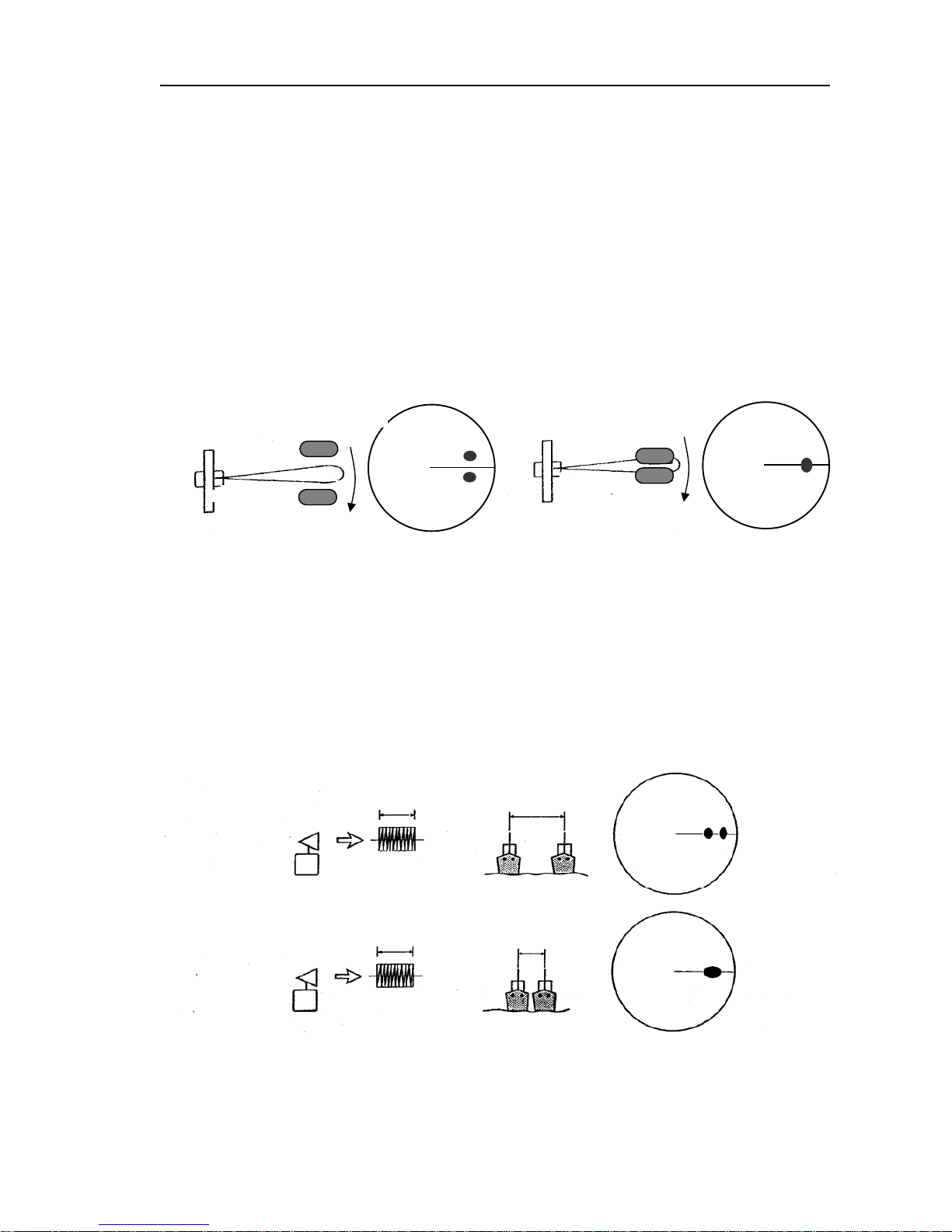
MDC-1840BB/1841BB/1860BB/1810BB/1820BB Series Chapter 5
Operation Manual Basic Operation
0093142122-10 5-19
Picture resolution
The picture resolution depends on the bearing and range discriminations that are
solely determined by the antenna horizontal beam width and the transmission pulse
length. These factors are defined in the following explanations and illustrations.
(1) Bearing discrimination
The bearing discrimination is defined as the minimum bearing where two targets of
the same distance are displayed as two independent images on the screen. The
bearing discrimination is determined by the aerial horizontal beam width.
(2) Range discrimination
The range discrimination is defined as the minimum distance where two different
targets situated in line on the same bearing are shown separated. The range
discrimination is dependent on the transmission pulse length.
Echoes from
two targets are
overlapped (not
Length of
transmission
pulse
Range
Between two
targets
Transmission
pulse
Range
between two
tar
g
ets
When the range between two targets is narrower than the
transmission pulse length.
Radar antenna
Radar antenna
Echoes from
two targets are
separated
The distance between two targets
in azimuth is longer than the radar
beam width.
The distance between two targets
in azimuth is shorter than the radar
beam width.
When the range between two targets is wider than the transmission pulse length.
Page 87
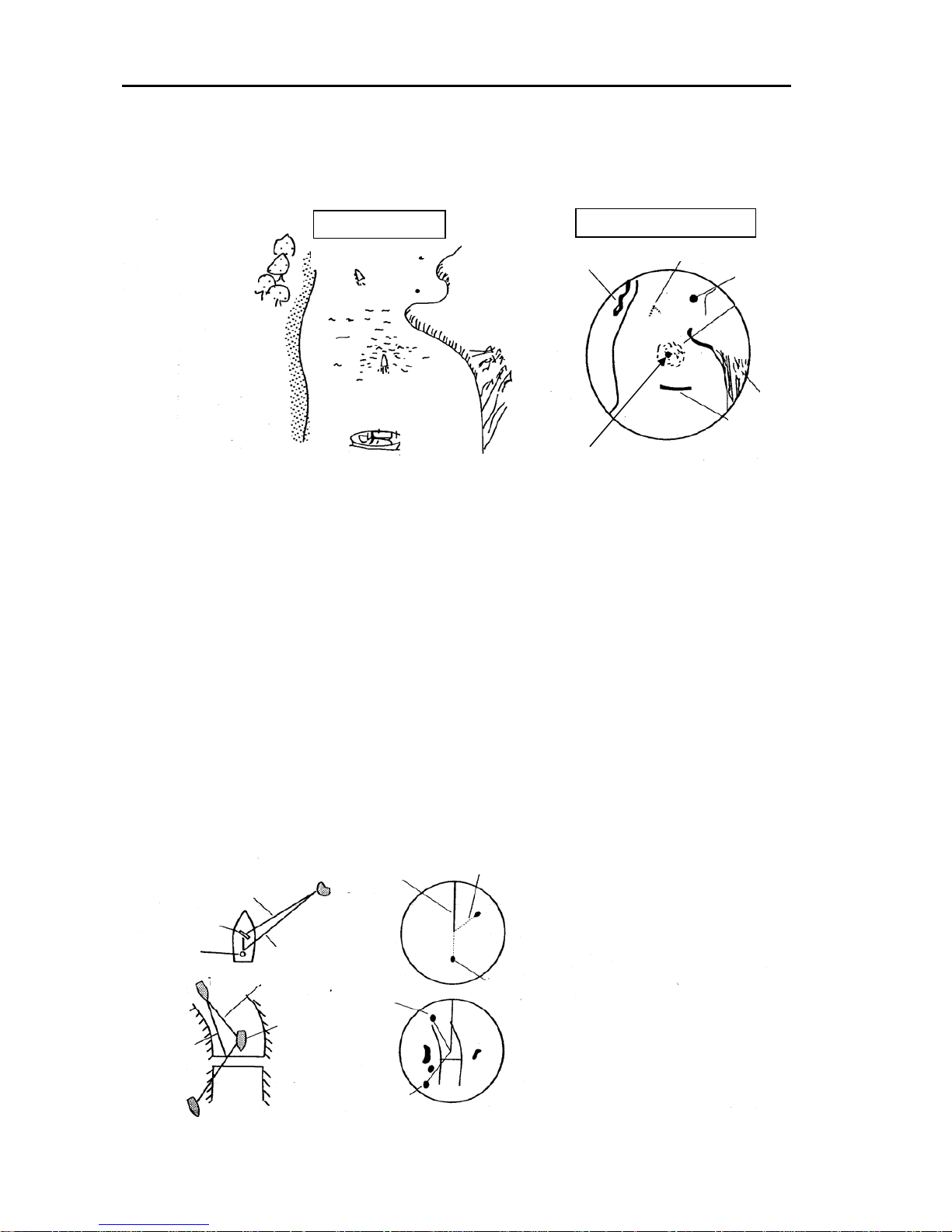
Chapter 5 MDC-1840BB/1841BB/1860BB/1810BB/1820BB Series
Basic Operation Operation Manual
5-20 0093142122-10
Reading the radar images
The following pictures illustrate how the radar picture is constituted from an actual
situation around your own ship.
False echoes
The operator should be fully aware of various false echoes caused by the radar
performance, terrain and structures on the land, as mentioned below.
(1) False echo caused by secondary reflection
An example of false echo
caused by the radar beam
reflected by an aft mast.
An example of a temporarily
produced false echo caused by
the radar beam reflected by a
large bridge.
z The buoy No.1 is not detected because the cape blocks it.
z The echo of the large boat is painted similar to its actual profile because of short
distance.
z The echo of a small boat is shown as a spot because it has a small echoing area.
z The hill located on the starboard (in the bearings of 90 deg to 130 deg) has a deep forest
zone, and its echoing area is large. It is represented as wide spreading echoes on the
screen.
z Since the sand beach on the port side is deep, but is not topographic. The echoes are
shown weak.
z The windbreak forest produces strong echoes, and it is shown as massive echoes in
high contrast.
z The echoes reflected from the sea surface change from time to time, depending on the
wind speed and direction.These echoes are shown as a group of spots.
Windbreak
forest
Small boat
Sheer cliff
Actual view
Echoes by windbreak forest
Echo of a small boat
Echo of buoy No.2
Echo of the sea return
Echo of the hill
Echo of a large ship
Large ship
Own ship
Picture on the screen
Own ship’s position
Buoy No.2
Buoy No.1
Antenna
Mast
Real target
Heading Marker
Real target
Boat
Direct reflection pass
Secondary Reflection pass
Target
False echo
Secondary
Reflection pass
False echo
Direct reflection pass
False echo
Page 88
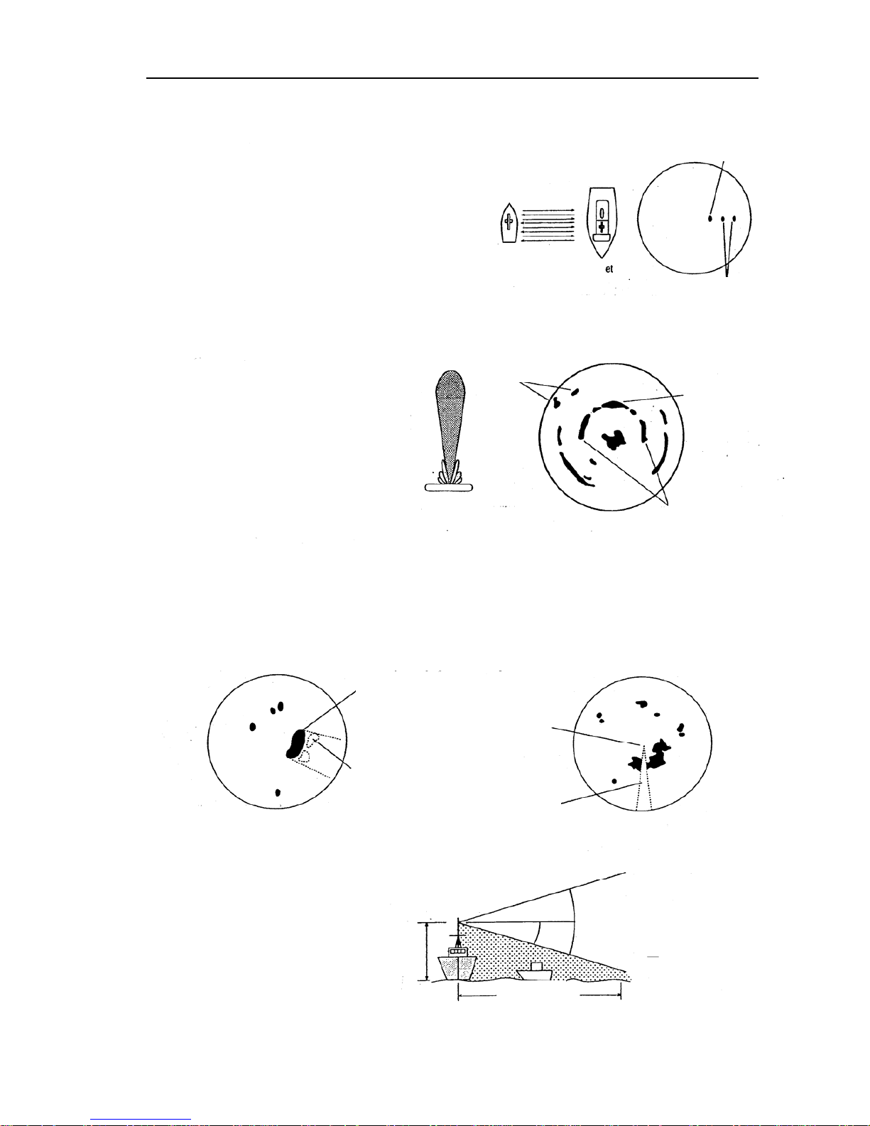
MDC-1840BB/1841BB/1860BB/1810BB/1820BB Series Chapter 5
Operation Manual Basic Operation
0093142122-10 5-21
(2) False echo caused by multiple echoes
(3) False echo caused by the side lobes
(4) Shadow and dead angle
When a boat passes near a large boat, radio waves
are repeatedly reflected between own boat and the
boat nearby, causing several echoes at regular
intervals to appear in the same bearing (Multiple
reflections). These false echoes produced by
multiple reflections are called multiple echoes. In this
case, the real target is the closest one. The multiple
echoes soon disappear when your boat moves from
the boat that caused the multiple reflections or, the
boat has changed her course. For this reason, the
true image can easily be identified.
The radio beam emitted from a radar
antenna contains some residual smaller
beams on both sides of the main beam.
These components are called the side
lobes. A closely located target with high
reflectivity can be displayed as an arc
caused by the side lobes. To reduce these
false echoes, reduce the gain slightly or
apply A/C sea control.
Height of antenna affects the short
range target detection. If the
antenna is mounted too high, the
radar beam may skip the target,
causing no echo detection. The
vertical beam width of the radar
antenna also affects the close range
detection.
True echo
Multiple echoes
Other targets
Real echo of a
strong target
False echoes of the
strong target caused
b
y
the side lobe
Antenna
Main lobe
Boat
Target
Picture of a close
in target
These echoes are not shown
caused by the dead angle
Shadow caused by a mast
and other structures nearb
y
The dead angle changes according to the
dimensions and distance of the structures.
Antenna
height
Width of vertical
beam
Unilluminated
area
If the funnel, mast or other structures are located near a radar antenna, the radar beam will be blocked,
causing a shadow area where no object will be detected by the radar. The angle of the shadow is called the
dead angle. To avoid the shadow, the radar antenna position should be changed to a better place to
minimize this effect. If this is not possible, the operator should be aware this dead angle exists while
operating the radar.
Page 89

Chapter 5 MDC-1840BB/1841BB/1860BB/1810BB/1820BB Series
Basic Operation Operation Manual
5-22 0093142122-10
APPENDIX 2: Receiving the Radar Beacons and SART
The X-band radar system is required to be capable of receiving signals emitted from a
Radar Beacon and a SART (Search and Rescue Transponder). To receive those
signals by the radar system, use the following procedures.
(1) Set the range scale to 6 or 12 NM.
(2) Turn off the Interference Rejection function from DISP/ECHO/IR menu item.
Refer to Para. 6.1.2 “IR (Interference Rejection).
(3) In case the radar picture is obscured with too many echo signals, detune the
receiver a little for better observation.
(4) When your vessel approaches the transmitting Radar Beacon or the SART, the
echoes will become blurred in an arc. For better observation of those signals,
adjust the Gain, Anti-clutter Sea and RAIN controls, as appropriate.
About SART
According to the GMDSS (Global Maritime Distress and Safety Systems) requirement,
the IMO/SOLAS class ships must be equipped with a SART. When a ship is in distress,
a signal will be automatically emitted from the SART so that other ships and/or
aircrafts can identify its location. When your ship carrying the X-band radar comes
within 8 miles of a ship in distress, the SART picks up the radar signal and responds to
it. The signal consists of 12 sweeps and is emitted in the frequency range of 9.2 GHz
through to 9.5 GHz. The SART has two sweep times that switch from slow sweep (7.5
us) to fast sweep (0.4 us) and vice versa, according to the distance. When the radar
receives this signal, a line of 12 dots, which is equally spaced at about 0.64 NM,
appears on the screen. The nearest blip of the SART indicates the location of the ship
in distress. When your vessel comes within 1 NM to the SART, a fast sweep signal is
displayed on the radar and a thin line connects the 12 blips.
Actual location of the ship carrying the SART
If your vessel is located at 1 NM or more away from the SART, the position at which
the first echo is displayed is 0.64 NM behind the actual SART position when the 12
SART echoes are identified. If your vessel comes within 1 NM from the SART, the fast
sweep signal is indicated. The position of this echo is displayed 150 meter beyond the
actual SART position.
Page 90

MDC-1840BB/1841BB/1860BB/1810BB/1820BB Series Chapter 5
Operation Manual Basic Operation
0093142122-10 5-23
The SART signal presentation and its signal timing
1 nm or more beyond
the SART position
Within 1 nm of the SART position
Beam width of the
radar signal received
SART
position
Current position
Bandwidth
of the radar
Signal
received
Slow sweep signal
SART position
Fast sweep signal
Slow sweep signal
Fast sweep signal
Sweep start
9,500 MHz
9,200 MHz
7.5μsec sweep time
95μsec sweep time
SART mark length
Page 91

MDC-1840BB/1841BB/1860BB/1810BB/1820BB Series Chapter 6
Operation Manual Using The Menu
93142122-07 Contents 1
Chapter 6
Using The Menu
Contents
Page No.
[Common key operation]....................................................................6-1
6.1 RADAR Menu............................................................................ 6-2
6.1.1 Picture Stabilization...........................................................................6-2
6.1.2 Ship’s Heading..................................................................................6-3
6.1.3 Ship's Speed.....................................................................................6-3
6.1.4 Set and Drift ......................................................................................6-3
6.1.5 Cursor Position..................................................................................6-4
6.1.6 Vector Time .......................................................................................6-4
6.1.7 CPA Alarm Limit.................................................................................6-5
6.1.8 Data indication...................................................................................6-5
6.2 DISP Menu................................................................................. 6-6
6.2.1 MARK ................................................................................................6-6
6.2.1.1 VRMs and EBLs........................................................................6-6
6.2.1.2 VRM Unit ..................................................................................6-7
6.2.1.3 RANGE RINGS.........................................................................6-7
6.2.1.4 BRG TRUE/REL (Bearing True or Relative)..............................6-7
6.2.1.5 STERN MKR (Stern Marker).....................................................6-7
6.2.1.6 CURSOR L/L (Cursor Position Indication) ................................6-7
6.2.2 ECHO (Echo Menu).............................................................................6-7
6.2.2.1 TRAILS (Echo Trail Setting)......................................................6-7
6.2.2.2 IR (Interference Rejection)........................................................6-7
6.2.2.3 ENH (Echo Enhancement)........................................................6-8
6.2.2.4 TUNE (Receiver Tuning Mode).................................................6-8
6.2.2.5 MAIN TUNE (Manual Tuning Set).............................................6-8
6.2.2.6 DAY/NIGHT (Day or Night Screen)...........................................6-8
6.2.3 NAV (Nav Menu) ...............................................................................6-8
6.2.3.1 STB (Screen Stabilizing Mode).................................................6-9
6.2.3.2 PLOT MODE (Plotting Mode)....................................................6-9
6.2.3.3 TARGET ALL CLEAR (Plotting T arget All Clear).......................6-9
Page 92

Chapter 6 MDC-1840BB/1841BB/1860BB/1810BB/1820BB Series
Using The Menu Operation Manual
Contents 2 93142122-07
Page No.
6.2.3.4 ID DISP (ID Number Display)................................................... 6-9
6.2.3.5 OUTLINE DISP (Outline Data Display)..................................... 6-9
6.2.3.6 AIS (Automatic Identification System s) Data Display ............... 6-9
6.2.3.7 Navigation Display, Map Function............................................ 6-9
6.2.3.8 TM RESET (True Motion Center Reset)................................. 6-10
6.2.3.9 OS PAST CRS (Own Ship's Past Course).............................. 6-10
6.3 ADJUST MENU......................................................................6-10
6.3.1 ADJUST............................................................................................ 6-10
6.3.1.1 Screen Contrast Settings........................................................ 6-10
6.3.1.2 Navigation Position Alignment.................................................6-11
6.3.1.3 RADAR SENSITIVITY (Selecting Auto/Man Receiver Functions).......6-11
6.3.2 PRESET ........................................................................................... 6-12
6.3.2.1 AUTO TUNE (Auto Tune Preset)............................................ 6-12
6.3.2.2 MANUAL TUNE (Manual Tune Center Preset)....................... 6-12
6.3.2.3 GAIN AUTO/MANUAL (Gain Preset) ...................................... 6-13
6.3.2.4 SEA AUTO/MANUAL/HARBOR (STC Preset)........................ 6-13
6.3.2.5 RAIN AUTO/MANUAL (FTC Preset)....................................... 6-13
6.3.2.6 MBS (Main Bang Suppression).............................................. 6-14
6.3.2.7 TARGET LEVEL (Target Detection Level).............................. 6-14
6.4 SYSTEM MENU......................................................................6-14
6.4.1 I/O SETUP........................................................................................ 6-14
6.4.1.1 HDG INPUT (Heading Input).................................................. 6-15
6.4.1.2 GYRO SET (Gyro Initial Setting) ............................................ 6-15
6.4.1.3 SEA STAB SPD (Water Speed Input)..................................... 6-15
6.4.1.4 GND STAB SPD (Ground Stabilized Input) ............................ 6-16
6.4.1.5 LOG PULSE (Log Pulse Rate)............................................... 6-17
6.4.1.6 GYRO (Gyro Gear Ratio)....................................................... 6-17
6.4.1.7 Serial Input Format................................................................. 6-17
6.4.1.8 SERIAL TRANSMIT (Serial Output Interval)........................... 6-17
6.4.2 SYSTEMSETUP............................................................................... 6-18
6.4.2.1 RANGE DISP (Range Scale Display)..................................... 6-18
6.4.2.2 BUZZER................................................................................. 6-18
6.4.2.3 LANGUAGE ........................................................................... 6-18
6.4.2.4 DELAY (Transmission Timing Adjustment)............................. 6-18
Page 93

MDC-1840BB/1841BB/1860BB/1810BB/1820BB Series Chapter 6
Operation Manual Using The Menu
93142122-07 Contents 3
Page No.
6.4.2.5 HDG (Ship’s Heading Adjustment)..........................................6-19
6.4.2.6 HEIGHT (STC Law Selection).................................................6-19
6.4.2.7 TM RESET (True Motion Reset Position) ...............................6-19
6.4.2.8 KEY SOUND (Key Click Sound) .............................................6-20
6.4.2.9 BUZZER FREQ (Buzzer Sound Frequency)...........................6-20
6.4.2.10 ALARM MODE (Alarm Zone Set Mode)..................................6-20
6.4.2.11 TRAIL MODE (Echo Trail Mode).............................................6-20
6.4.2.12 OFF CENTER (Off-center Mode)............................................6-21
6.4.2.13 GYRO/LOG (own ship’s information)......................................6-21
.
6.4.3 BITE (Built In Test Equipment)............................................................6-21
6.4.3.1 ALARM TEST (Alarm System Test) ........................................6-22
6.4.3.2 ATA TEST (ATA Tracking Test Mode)......................................6-22
6.4.3.3 Hour Meter..............................................................................6-23
6.5 MAINTENANCE MENU........................................................ 6-23
6.5.1 ANTENNA.......................................................................................6-23
6.5.2 OPTION...........................................................................................6-23
6.6 Operation of the EPA............................................................... 6-24
6.6.1 Using the EPA.................................................................................6-24
6.6.2 CPA and TCP A................................................................................6-25
6.6.3 EPA plotting on the screen ..............................................................6-25
6.6.4 Alarm display...................................................................................6-26
6.6.5 Explanation of the EPA terms..........................................................6-26
6.6.6 VECT TIME (Selecting the Vector Time).........................................6-27
6.6.7 EPA symbols ...................................................................................6-27
6.6.8 WARNING LIMIT (Setting the Warning Limit of CPA and TCPA).....6-28
6.6.9 TARGET ALL CLEAR (Clearing all target plots)..............................6-28
6.6.10 ID DISP (Displaying Target ID Number) ..........................................6-28
6.6.11 Correcting the latest plotting position ..............................................6-28
6.7 Operating the ATA....................................................................6-29
6.7.1 Using the ATA..................................................................................6-29
6.7.2 Outline of the ATA system................................................................6-29
6.7.3 ATA functions...................................................................................6-30
6.7.4 Operating procedures......................................................................6-30
Page 94

Chapter 6 MDC-1840BB/1841BB/1860BB/1810BB/1820BB Series
Using The Menu Operation Manual
Contents 4 93142122-07
Page No.
6.7.5 ATA symbols ................................................................................... 6-31
6.7.6 Setting the Guard Zone................................................................... 6-32
6.7.6.1 To set up the position of the Guard Zone ...............................6-32
6.7.6.2 To set up the depth and width of the Guard Zone...................6-32
6.8 Operating the AIS..................................................................... 6-33
6.8.1 Outline of AIS...................................................................................... 6-33
6.8.2 Setting the AIS to work........................................................................ 6-33
6.8.3 AIS data display..................................................................................6-34
6.8.4 AIS target symbols..............................................................................6-35
6.9 Operating the Interswitch ....................................................... 6-37
6.9.1 Outline of Interswitch .......................................................................... 6-37
6.9.1.1 System Diagram .....................................................................6-37
6.9.2 System Setting Modes..........................................................................6-38
6.9.2.1 NORMAL.................................................................................6-38
6.9.2.2 CROSS...................................................................................6-38
6.9.2.3 MASTER-SLAVE.....................................................................6-38
6.9.2.4 DUAL ...................................................................................... 6-39
6.9.3 Operation.............................................................................................. 6-39
6.9.3.1 MODE.....................................................................................6-39
6.9.3.2 TYPE.......................................................................................6-40
6.9.3.3 STATUS .................................................................................. 6-40
6.9.3.4 ANTENNA...............................................................................6-40
6.9.3.5 Examples for Setting...............................................................6-40
6.9.4 Data output function .............................................................................6-42
6.9.5 Installation ............................................................................................6-43
6.9.6 Adjustment............................................................................................ 6-43
6.9.7 Option...................................................................................................6-44
6.9.7.1 radar image bearing offset ...................................................... 6-44
6.9.7.2 heading information offset....................................................... 6-44
6.9.8 Cable Connection.................................................................................6-45
Page 95

MDC-1840BB/1841BB/1860BB/1810BB/1820BB Series Chapter 6
Using The Menu Operation Manual
93142122-07 6-1
Chapter 6 Using The Menu
[Common key operation]
All menu-driven functions can be selected by the same key sequence. In the menu,
there are four main menus available such as RADAR, DISP (Display), ADJUST, and
SYSTEM.
The RADAR menu provides operational sub menus, used in setting up parameters for
picture stabilizing mode and EPA/ATA functions.
The DISP menu provides sub menus that set on-screen marks, cursor, echo trails,
plotting mode selection, etc. all used for screen display.
The ADJUST menu is protected from ordinary operations. This menu provides
operational sub menus for adjustments and presets for the screen display, including
video contrast controls for radar, markers, alpha-numeric characters, presetting
manual/auto tuning functions, manual/auto GAIN, SEA, RAIN functions, etc.
The SYSTEM menu is also protected. The menu provides technical sub menus used
for setting up various technical parameters of the radar system during installation or
post repair adjustments.
To select the menu items, use the following procedures.
(1) Press the MENU key and use the Joystick to select an item. The selected item is
12 NM
090
HDG 045.2゜
054.9゜
SOG
20
.
4KT
MAN
DRIFT
20
.
3KT
SET
083
.
6゜
VRM
TRUE
PI
115.0゜
PI
0.025NM
EBL
>230.0゜
263.0゜
>0.053NM
0.093NM
TRUE
2NM
H
UP
RM(R)
TUNE AUTO
GAIN
SEA
RAIN
MAN
AUTO
AUTO
COG
LAT
LON
RNG
T BRG
WP RT01 DGPS
LAT
LON
R02
.
345 NM
CURSOR
TARGET
XTE
AGE
CPA
TCPA
COG
T BRG
RNG
SOG
3
.
0 MIN
2
.
6NM
5
.
3 MIN
126
.
8゜
21
.
7KT
338
.
4゜
13
.
7NM
VECT 3 MIN
BRG 090
.
0°
ID
TARGET ID
COG
SOG
21
.
7KT
CPA
TCPA
4
.
3NM
12
.
6MIN
100
110
120
130
140
150
160
170
080
070
060
050
040
030
020
010
270
260
250
240
230
220
210
280
290
300
310
190
200
320
330
340
350
000
180
MAN
LIM CPA
TCPA
0
.
5NM
5
.
3MIN
EPA DATA
338.0゜
338
.
0゜
13
.
7NM
X-BAND
LP
IR1
ENH
TRAILS
12 MIN
O
FFSET
BZ OFF
O
FF SENT
PM
2
1
UNRELIABLE
12
MMSI
431023652
PLOT DATA
AIS DATA
LIM 3
.
0NM
POSITION
NO VALID SENSOR
RADAR DISP
ADJUST
SYSTEM
GYRO
GND
STAB
35゜38
.
632N
139゜06
.
352E
SPD
20
.
4KTLOG
STAB
MAN
TRUE
OWNSHIPDGPS
LAT
LON
35゜38
.
632N
139゜06
.
352E
35゜38
.
632N
139゜06
.
352E
RADAR
DEPTH
TEMP
156
.
4M
13
.
4℃
DISP
ADJUST SYSTEM
WIDTH 090.0°
RNG 9
.
0NM
DEPTH 3
.
2NM
ALARM
AIS ON
MAP N
o
1
VAV ALIGN
OS PAST POSN
HDG
045
.
2゜
054.9゜
SOG
20
.
4KT
MAN
DRIFT
20
.
3KT
SET
083
.
6゜
COG
LAT
LON
RNG
TBRG
WP RT01 DGPS
LAT
LON
R02
.
345 NM
CURSOR
TARGET
XTE
CPA
TCPA
COG
TBRG
RNG
SOG
2
.
6NM
5
.
3MIN
21
.
7KT
338
.
4゜
13
.
7NM
VECT 3 MIN
ID
MAN
LIM CPA
TCPA
0
.
5NM
5
.
3MIN
ATA DATA
338
.
0゜
338
.
0゜
13
.
7NM
1
UNRELIABLE
PLOT DATA
GYRO
GND
35゜38.632N
139゜06
.
352E
SPD
20
.
4KTLOG
MAN
TRUE
OWN SHIP DGPS
LAT
LON
35゜38
.
632N
139゜06
.
352E
35゜38
.
632N
139゜06
.
352E
DEPTH
TEMP
156
.
4M
13
.
4℃
STAB
STAB
RNG
T BRG
4
.
3NM
126
.
8゜
126
.
8゜
TARGET ID
COG
SOG
21
.
7KT
CPA
TCPA
4
.
3NM
12
.
6MIN
2
MMSI
431023652
AIS DATA
LIM 3
.
0NM
NO VALID SENSOR
RNG
TBRG
4
.
3NM
126
.
8゜
POSITION
Page 96

Chapter 6 MDC-1840BB/1841BB/1860BB/1810BB/1820BB Series
Using The Menu Operation Manual
6-2 93142122-07
highlighted. Subsequent pressing of the MENU key brings back to the normal
operation.
1) Press the MENU key.
2) Highlight a desired menu by pressing the Joystick.
3) Highlight a desired sub menu or item by pressing the Joystick up or down.
4) Press the ENT key to activate the selection sequence or select the sub menu.
5) Press the Joystick up or down to select a status or parameter of the item
selected. When the parameters are identified with numbers (1:PANEL,
2:MODE, 3:TRUE/REL, etc.) the numerical keypad can also be used for the
selection.
6) Press the ENT key to fix the selection. The highlighted part is removed and its
function becomes effective.
7) Press the Joystick up or down to select the item.
8) Press the ENT key to activate the selection sequence.
9) Press the Joystick up or down to select a status or parameter of the item
selected. When the parameter is numerical, the numerical keypad can be used
for the selection.
10) Press the ENT key to fix the selection.
6.1 RADAR Menu
The RADAR menu includes the setting and display items used for the ordinary radar
operations.
6.1.1 Picture Stabilization
Indication Meaning Selection
SEA STAB/GND STAB Stabilizing mode indication SEA GND (Note)
NOTE 1: The under lined is a default value.
NOTE 2: To change the selection, go to DISP=>SEA STAB/GND STAB.
SEA (Sea Stabilized mode): The radar picture is stabilized with respect to the water
with signals supplied from a bearing sensor and a water speed sensor. The current
direction (Set) and speed (Drift) are combined in the motion of targets on the screen.
GND (Ground Stabilized mode): The radar picture is stabilized with respect to the
ground with the signals supplied from a bearing sensor and a speed sensor (either a
NOTE: When you have finished setting the relevant menu functions, exit the menu by
pressing the MENU key to make sure the settings become active.
Page 97

MDC-1840BB/1841BB/1860BB/1810BB/1820BB Series Chapter 6
Using The Menu Operation Manual
93142122-07 6-3
water speed sensor or a ground speed sensor). When a water speed sensor is used,
a tidal effect causes the deviation in picture stabilization. In such a case, the Set and
Drift correction must be made by manual means or NMEA signal. Refer to Para
6.4.1.3 and 6.4.1.4 for details.
6.1.2 Ship’s Heading
GYRO HDG
Indication Meaning Selection
GYRO HDG Gyro heading indication None
NOTE: This item is for display only.
6.1.3 Ship's Speed
Indication Meaning Selection
LOG/DOLOG SPD Ship's Speed indication LOG or DOLOG
LOG: Magnetic Log or Mechanical Log.
DOLOG: Doppler Log.
NOTE: This item is for display only. To change the selection, go to SYSTEM => I/O
SETUP => SEA STAB SPD or GND STAB SPD.
Indication Meaning Selection
MAN SPD Manual Speed 0 to 99.9 (KT)
NOTE: To set the speed, go to SYSTEM => IO SETUP => SEA STAB SPD.
Indication Meaning Selection
MAN COG Course Over Ground indication N.A.
SOG Speed Over Ground indication N.A.
NOTE: This item is for display only.
6.1.4 Set and Drift
When the GND STAB (Ground Stabilized) mode is selected via SYSTEM/IO
SETUP/GND STAB SPD, the Set and Drift data is displayed.
Indication Meaning Selection
MAN SET Direction of the current 0 to 359.9 (Deg.)
DRIFT Speed of the current 0 to 99.9 (KT)
To set or change setting, go to SYSTEM/IO SETUP/GND STAB SPD.
Page 98
Chapter 6 MDC-1840BB/1841BB/1860BB/1810BB/1820BB Series
Using The Menu Operation Manual
6-4 93142122-07
6.1.5 Cursor Position
Indication Meaning
CURSOR T BRG Cursor True or Relative(R) Bearing indication
RNG Cursor Range
LAT Cursor Latitude
LON Cursor Longitude
[Data Indication]
OWN SHIP DGPS Own Ship Information (Input Device Name)
(Select with DATA DISP key)
LAT Latitude/COG/LOP1
LON Longitude/SOG/LOP2
WP RT01 DGPS Waypoint Information/Route Name/Input Device
LAT Latitude/Bearing
LON Longitude/Range
XTE Cross Track Error
DEPTH K (W) Depth
NOTE: K means the depth from the Keel, W means the depth from Water surface.
WATER TEMP Water Temperature
6.1.6 Vector Time
The vector indication mode can be set with the TRUE/REL key. A vector time can be
set from the following menu.
NOTE: To use this function the heading and latitude/longitude data must be supplied from
the gyro/log interface unit KSA-08A and a GPS or Loran-C navigator unit.
z When no bearing data is entered from the gyrocompass, the latitude and longitude
display will turn to “XXX.XX.XXX”.
z The position data may deviate when a navigator unit is used in latitude above 70
degrees.
z
To use the EPA and ATA functions, the bearing and speed information must be
supplied from external bearing and speed sensors.
CAUTION:
Page 99

MDC-1840BB/1841BB/1860BB/1810BB/1820BB Series Chapter 6
Using The Menu Operation Manual
93142122-07 6-5
Indication Meaning Selection
TRUE (REL) VECT Vector Indication Time OFF, 30SEC, 1MIN,
3MIN, 6MIN, 12MIN,
30MIN, 60MIN
6.1.7 CPA Alarm Limit
This function is used to set up the warning limit at which the CPA and TCPA alarms
are activated. Use the following procedure to set up.
(1) Highlight the item and press the ENT key.
(2) Move the Joystick up or down to select the value and press the ENT key.
(3) Setting ranges for CPA and TCPA are as follows:
ATA CPA: 0.00 NM to 19.9 NM.
ATA TCPA: 1 Minute to 63 min.
AIS LIM CPA: 0 NM to 19.9 NM
AIS TCPA: 1 to 63 min.
Indication Meaning Selection
LIM CPA Limit for CPA (NM) 0 to 19.9 (NM)
TCPA Limit for Time to CPA (Min.) 1 to 63 (Min.)
6.1.8 Data indication
The following data are shown in the data window.
------------------------------------------------------------------
EPA/ATA DATA Plot Mode
(Select with DISP/NAV/PLOT MODE menu. ATA: option)
TARGET ID ID for Operating Target
AGE EPA Life
CPA Closest Point of Approach
TCPA Time to CPA
CSE/COG Course/Course Over Ground
STW/SOG Speed Through Water/Speed Over Ground
RNG Range
T BRG True Bearing
-------------------------------------------------------------------
AIS DATA (ON/OFF with DISP/NAV/AIS menu)
LIM Indicating Range ----------- 1.0 to 20.0 (NM)
AIS data will be displayed inside the range of LIM setting.
TARGET ID Target ID for Data Indication -------- 1 to 64
Set the ship's ID to data display.
Page 100

Chapter 6 MDC-1840BB/1841BB/1860BB/1810BB/1820BB Series
Using The Menu Operation Manual
6-6 93142122-07
MMSI Ship's ID
CPA Closest Point of Approach
TCPA Time to CPA
CSE/COG Course/Course Over Ground
STW/SOG Speed Through Water/Speed Over Ground
RNG Range
T BRG True Bearing
6.2 DISP Menu
The DISP menu has three sub menus; MARK, ECHO, and NAV. Each menu has the
following sub menus.
6.2.1 MARK
The MARK menu has various markers such as VRM (Variable Range Marker), EBL
(Electronic Bearing Line), Stern Marker and Cursor L/L (Position Cursor) that can be
turned on or off. This menu also has the bearing mode control that affects the bearing
indication of the EBL and vectors.
6.2.1.1 VRMs and EBLs
VRM 1 and 2, EBL 1 and 2, and PI (Parallel Index Line) can be set with the menu.
1st VRM Variable Range Marker No.1 OFF, ON
2nd VRM Variable Range Marker No.2 OFF, ON
1st EBL Electronic Bearing Line No.1 OFF, ON
2nd EBL Electronic Bearing Line No.2 OFF, ON
PI Parallel Index Line Cursor OFF, ON
To change the bearing and interval of the parallel index line, use the following
procedure:
1) Set the screen to normal display mode.
2) Keep pressing the EBL SEL key until the wedge symbol points to the letters PI,
shown in the left bottom of the screen. In the same manner, press the VRM SEL
key until the wedge symbol points to the letters PI in the right bottom of the screen.
3) Rotate the EBL control to move the PI in azimuth and the VRM control to change
the interval of the index lines.
NOTE: The underlined items are default values.
 Loading...