

Koden KGP-925 Operation Manual

Amendment History
KGP-925 Operation Manual
Doc No: 0093192502
Doc. No.-Rev. No.
No.
0 0093192502-00
1 0093192502-01
2
3
4
5
6
7
8
9
10
11
12
13
Revised Date
Y/M/D
2011/10/27
2012/08/16
Revised Content
First issue
Add internal beacon receiver type
14
15
16
17
18
19
Amendment policy
When any change is applied in the document, only the document number of the relevant sheet(s) and
cover sheet are modified and the rest of the sheets are not changed. The document number is shown in
the footer area, right or left bottom of each sheet.
c
○
2011- 2012 Koden Electronics Co.,Ltd. All rights reserved.
No part of this publication may be reproduced, transmitted, translated in any form by any means without
the written permission of Koden Electronics Co., Ltd. The technical descriptions contained in this
publication are subject to change without notice. Koden assumes no responsibility for any errors,
incidentals or consequential damages caused by misinterpretation of the descriptions contained in this
publication.

KGP-925 Preface
Safety Precautions
Disconnect Main Power
It is still possible to receive an electric shock caused by unintentionally switching on the power during
repair work. To prevent this from happening, make sure to completely disconnect the unit from the
ship’s main supply before attempting any inspection and repair.
Dust
Dust can accumulate inside the unit after long periods of use. Allergies can result from the inhalation of
this dust, therefore during inspection and cleaning it is advisable to use a mask.
Static Electricity
Static sensitive semiconductor devices are used in this unit. Before changing the printed boards be
careful not to damage any of these devices due to electrostatic build up from carpet, clothes, seats, etc
Liquid Crystal Display
A Liquid Crystal Display contains mercury, which is harmful to the human body when touched. When
you attempt to discard this device, follow the proper disposal procedures.
0093192502-01 (1)
Preface KGP-925
Symbols used in this manual
The following symbols are used in this manual. You are requested to be fully aware of the meaning of
each symbol before carrying out inspection and maintenance of this equipment.
Alarm mark
Alarm
Caution mark
To handle the equipment ignoring this sign may lead to injury to the
human body or damage to the equipment.
Caution
Warning High Voltage mark
Prohibition mark
To handle the equipment ignoring this sign may lead to a
malfunction of the equipment.
To handle the equipment ignoring this sign may lead to electrical
shock to the human body.
This sign indicates that a specified action is prohibited. The
prohibited action will be shown in the vicinity of the mark.
(2) 0093192502-01

KGP-925 Preface
How to use this manual
Scope of this manual
This manual contains information about installation, operation and maintenance of the KGP-925
GPS/GLONASS navigator.
Structure of this manual
This manual is divided into sections according to the contents as described below. This arrangement
will help you overview the whole contents as well as refer to detailed information for your specific
requirement.
Chapter 1: General Information
- About GPS and GLONASS
- Outline of the equipment
- Equipment composition
- Software type name
- Corresponding with Techni cal Regulations
Chapter 2: Equipment Composition
- Standard equipment list
- Optional items list
Chapter 3: Specification
- GPS/GLONASS receiver section
- Display section
- Data Input/Output
- Power requirements
- Compass safe distance
- Environmental conditions
- External dimensions and weight
Chapter 4: Installation
- Installation consideration
- Unpacking of the goods
- Inspection of the goods
- Siting the units
- Display unit installation
- Antenna unit installation
- Cable connections to the KGP-925
- Connector pin outs
- Inspection after installation
0093192502-01 (3)

Preface KGP-925
Chapter 5 : Basic Operation
- The name and function of each part
- Power On/Off
- Adjusting display contrast and brightness
- Selecting the screen
- Storing present position (EVENT)
- Using MOB (Man over-board) key
- Recalling event or MOB position
- Displaying average speed, average bearing and elapsed time
Chapter 6: Various Navigation
- Storing waypoint (LAT/LONG) data
- Setup of waypoint navigation
- Cross track error and course deviation angle
- Storing and erasing routes
- Route setup
- Setting an anchor position
- Track display
Chapter 7: Alarms
- Kinds of alarms
- Alarm explanation
- Setting and canceling
Chapter 8: Setup Procedure
- Menu options
- Menu 3: GNSS
- Menu 4: Differential GNSS (DGNSS)
- Menu 5: Compensation
- Menu 8: Initial setting
- Menu 9: Interface
- Initialization
Chapter 9: How to use LOPs
- Initial setup for LOPs display
- Storing waypoints (LOPs data)
- Correcting your position (LOPs)
- Calculating LOPs based on LAT/LONG data
(4) 0093192502-01

KGP-925 Preface
Chapter 10: Maintenance and Troubleshooting
- Periodic inspection and cleaning
- Troubleshooting
Chapter 11: Technical Reference
- Digital interface (IEC 61162-1 Ed.4)
Chapter 12: Communication with external navigation system
- Changing to the EXTERNAL mode
- Route data transfer
Annex
- Menu Tree
- DGNSS beacon reference stations list
- Decca zone
0093192502-01 (5)

KGP-925 Chapter 1 General Information
Chapter 1 General Information
Page No.
1.1 About GPS and GLONASS......................................................................1-1
1.1.1 General.............................................................................................................1-1
1.1.2 Positioning by GPS/GLONASS......................................................................1-1
1.1.3 Time required for position fix.........................................................................1-1
1.2 Outline of the equipment.........................................................................1-2
1.3 Equipment composition..........................................................................1-2
1.4 Software type name.................................................................................1-2
1.5 Corresponding with Technical Regulations ..........................................1-4
0093192502-00 Contents
KGP-925 Chapter 1 General Information
Chapter 1 General Information
1.1 About GPS and GLONASS
1.1.1 General
GPS is a navigation system using 24 satellites (21 plus 3 in service) orbiting 20,183 km high from the
earth every 11 hours 58 minutes. And GLONASS is orbiting 19,100 km high from the earth 11 hours 15
minutes.
1.1.2 Positioning by GPS/GLONASS
Your position is determined by calculating the distance from two satellites (in 2-dimensional p ositioning)
or three satellites (in 3-dimensional positioning) to your position. The distance is determined b y the time
taken for a message to be sent from the satellites to the receiver. In 2-dimensional positioning, your
position (latitude and longitude; height is preset) is determined at the intersection point of three spheres
formed by three satellites. In 3-dimensional positioning, your position (latitude, longitude and height) is
determined at the intersection point of four spheres formed by four satellites.
NOTE
The GPS system is based on a geodetic system called WGS-84 and The GLONASS system is
based on a geodetic system called PZ-90. In conventional world map, one coordinate system
differs from others with region, and this causes the position fix made on the map and GPS
measurement to differ to a certain extent.
1.1.3 Time required for position fix
In the following circumstances, your GPS/GLONASS receiver takes more time to fix position:
(1) When you turned the GPS/GLONASS receiver for the first time.
(2) The stored orbital dat a is not suitable for the available satellite, or purged due to lengthy storage.
(3) When you use it after moving a long distance
The GPS/GLONASS receiver first turned on starts to store the orbital data sent from the satellite. It
takes about 2 or 3 minutes before the first fix is available. After this, the receiver can fix your position
within a minute by using the previously stored data.
0093192502-01 1-1
Chapter 1 General Information KGP-925
1.2 Outline of the equipment
The KGP-925 of GPS/GLONASS navigator is designed and manufactured to meet the carriage
requirement of the latest IMO/SOLAS regulation and its harmonized IMO resolution MSC.115(73) and
IEC technical standards, shown below.
IEC 60945 4
IEC 61108-1 Ed.2.0 2003-07: Ship borne GPS-Receiver
IEC 61108-2 Ed.1.0 1998-06: Ship borne GLONASS-Receiver
IEC 61162-1 Ed.4.0 2010-11: Digital Interface
th
Edition 2002-08, General
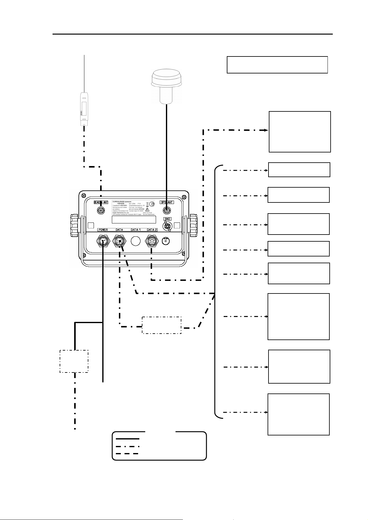
1.3 Equipment composition
The equipment composition of KGP-925 is shown in Figure 1.1.
1.4 Software type name
The following software type is used in KGP-925 GPS/GLONASS navigator.
Software type Application
KM-F14A Main logic board
1-2 0093192502-01
KGP-925 Chapter 1 General Information
*RA-14 is a name in the KODEN
DC Power cable
Power
rectifier
PS-010
10.8 to 31.2VDC
AC Power cable
100/115VAC
200/230VAC
Whip antenna
BA-03(*RA-14)
(Option)
Beacon antenna
coupler
BA-02L-K
(Option)
*If connected more than two units,
JB-10 is required
Antenna unit
MA-620G
Junction Box
JB-10
Legend
Standard configuration
Option
Prepared by a customer
NOTE: Connecting cable is option
Chart plotter
Marine radar
Echo sounder
Auto pilot
AIS
(Other brand)
Chart plotter
GTD-110/150
Plotter sounder
CVG-80/200
Echo sounder
CVS-841series
CVS-842/852series
Echo sounder
CVS-126/128series
Echo sounder
CVS-1410 series
AIS transceiver
CVS-FX series
KAT-100
Marine radar
MDC-900series
MDC-1800series
MDC-2000series
MDC-2200series
MDC-2500series
MDC-2900series
Marine radar
MDC-700series
MDC-1000series
MDC-1500series
MDL-1 100series
Chart plotter
Marine radar
Echo sounder
Auto pilot
AIS
(Other brand)
Figure 1.1 Equipment composition of KGP-925
0093192502-01 1-3
Chapter 1 General Information KGP-925
1.5 Equipment composition
1.5.1. « Shipborne combined GPS/GLONASS Receiver Equipment, type «KGP-925» meets the
requirements of Technical Regulations about safety of internal water transport objects, approved by
Resolution of the Russian Federation Government #623 dated August 12, 2010 and requirements of
Technical Regulations about safety of Maritime transport objects, approved by Resolution of the
Russian Federation Government #620 dated August 12, 2010.»
1.5.2. « Shipborne combined GPS/GLONASS Receiver Equipment, type «KGP-925» determined as
objects of Technical Regulation.»
1.5.3. «According to the article 27 FZ of Federal Law 184-FZ «About Technical Regulation» dated
December 12, 2002 and Resolution of the Russian Federation Government dated 19.11.03 :0696
Shipborne combined GPS/GLONASS Receiver Equipment, type «KGP-925» has an appropriate
marking.
The marking can be performed by one of four variants, depending on surface color of equipment.
The marking of navigation should be done by the manufacturer (supplier) and should be applied right t o
device surface.»
1.5.4. « Shipborne combined GPS/GLONASS Receiver Equipment, type «KGP-925» has marking by
caution plates in Russian and English.»
«HIGH VOLTAGE»
1.5.5. « Shipborne combined GPS/GLONASS Receiver Equipment, type «KGP-925» is tested
according to international standard and meet the requirements of International standard IEC 60945.
According to the requirements of clause 4.9. of the International Standard IEC 60945 Shipborne
combined GPS/GLONASS Receiver Equipment, type «KGP-925» is marked externally with the
following information, where practicable:
- identification of the manufacturer;
- equipment type number or model identification under which it was type tested;
- serial number of the unit;
- supply voltage;
- minimum safe distance at which it may be mounted from
main or steering magnetic compasses (according to sub clause 4.5.3. of IEC 60945);
1-4 0093192502-01
KGP-925 Chapter 1 General Information
- Production date;
- Power consumption;
- Weight;
- Recycling method;
- IP;
- Compliance with IEC 60945.»
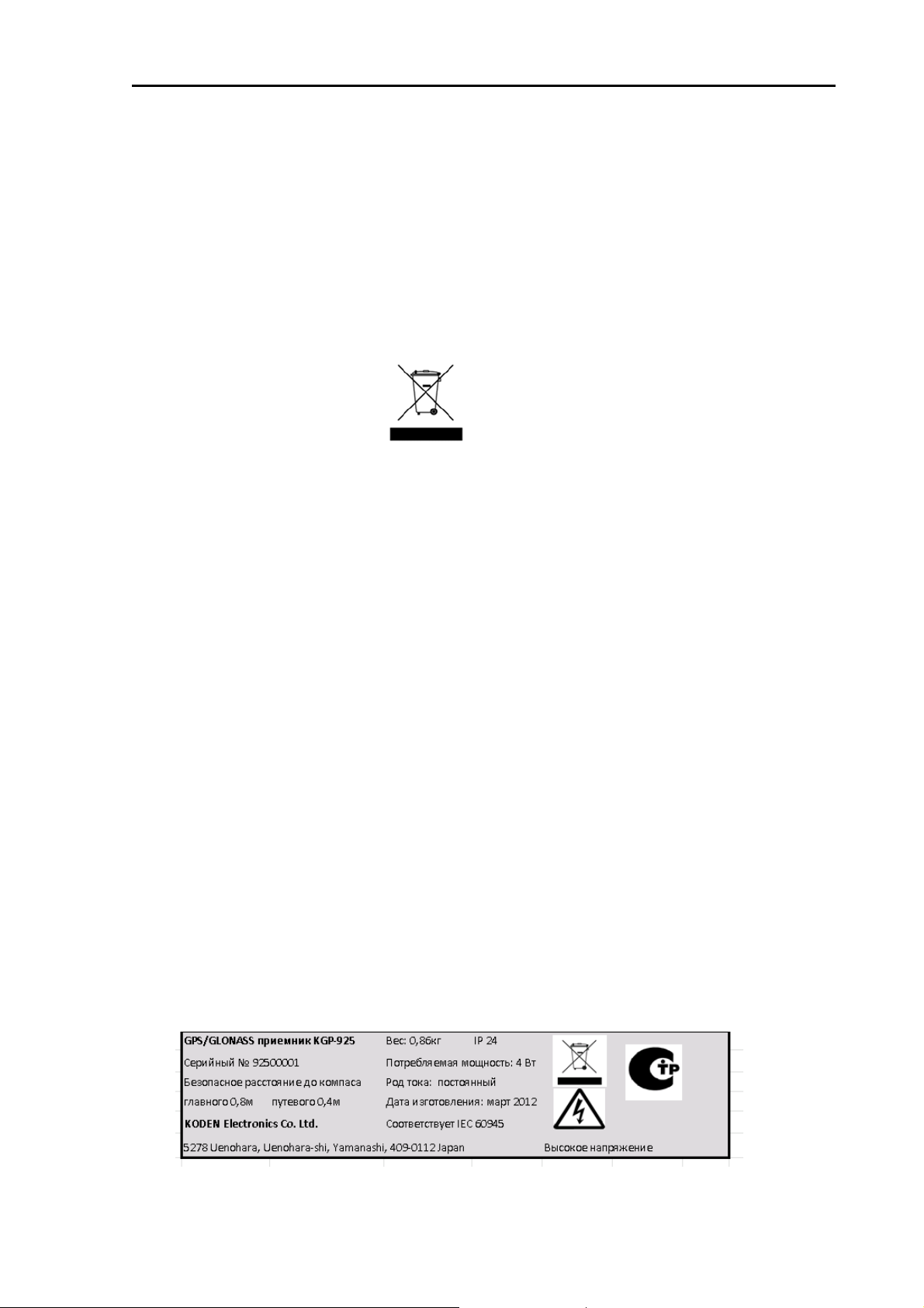
1.5.6. « Shipborne combined GPS/GLONASS Receiver Equipment, type «KGP-925» has appropriate
marking about the recycling method.
Recycling of navigation and should be organized according to the Federal Law about industrial
waste :89-FZ dated 24.06.98 in the acting edition. Recycling of Shipborne combined GPS/GLONASS
Receiver Equipment, type «KGP-925» , accumulator batteries and other equipment should be done
only by organizations registered in Assay Chamber and approved for utilization of the defined type of
products with mentioning the owner of the waste.
Guidelines for recycling:
1. Shutting off the equipment from power supply source, pulling out of accumulator batteries;
2. Disassembling of the equipment by hand, extracting dangerous elements and material suitable for
repulping (unsoldering of radioelements, precious metals, disassembling of plastic parts a nd etc.);
3. Separating of elements by hazard class and material type;
4. Delivering of separated elements for recycling to specialized collection station.
1.5.7. «Shipborne combined GPS/GLONASS Receiver Equipment, type «KGP-925» is produced
according to the advanced technologies and meet the requirements of the Federal Law of the Russian
Federation # 261-FZ
«About power saving and of energy efficiency and about making amendments in separate acts of
legislation of the Russian Federation» dated November 23, 2009 in current version.»
An example of label of Shipborne combined GPS/GLONASS Receiver Equipment, type «KGP-925»
0093192502-01 1-5

KGP-925 Chapter 2 Equipment Composition
Chapter 2 Equipment Composition
Page No.
2.1 Standard equipment list ........................................................................2-1
2.2 Option items list....................................................................................... 2-1
0093192502-00 Contents
KGP-925 Chapter 2 Equipment Composition
Chapter 2 Equipment Composition
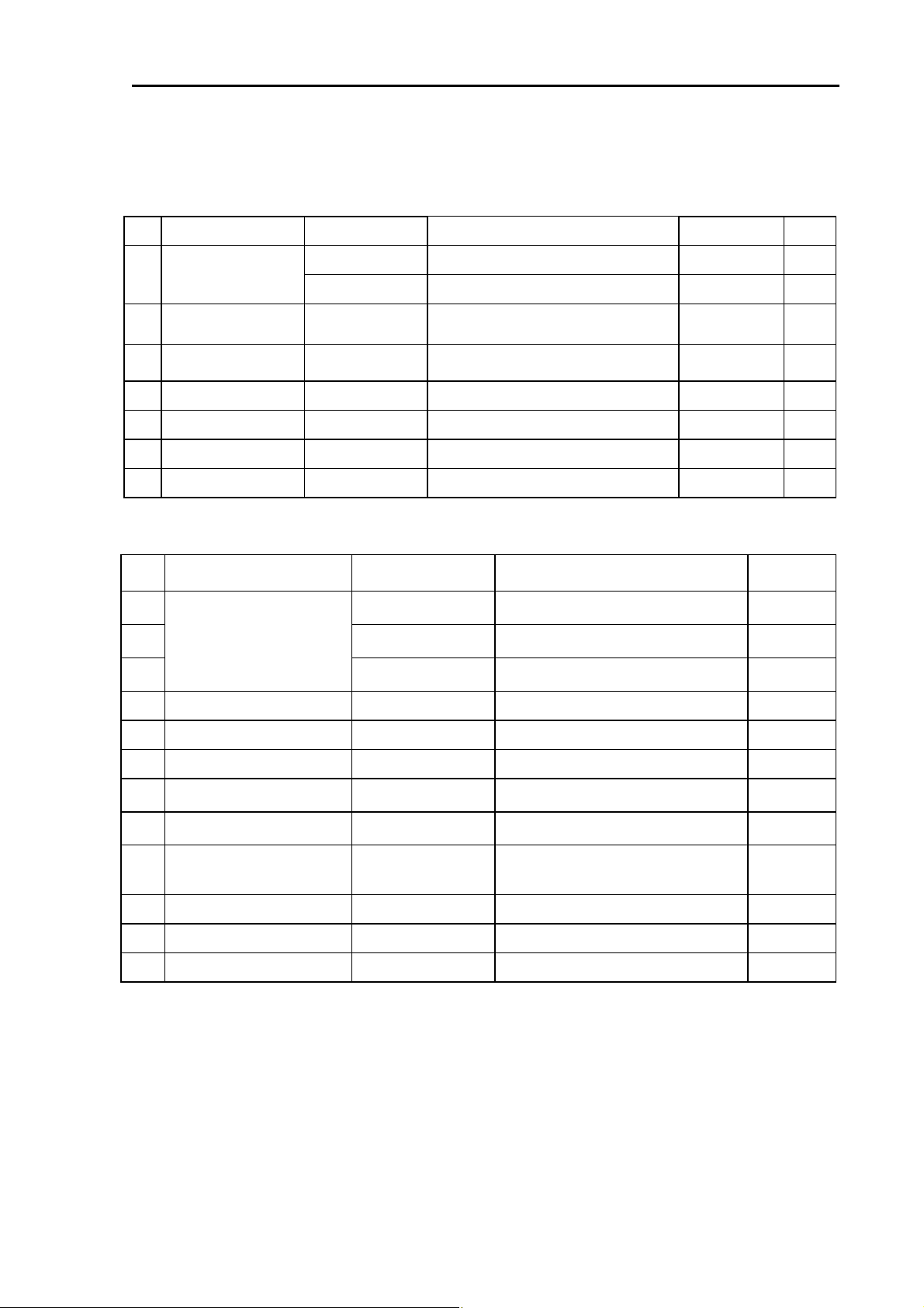
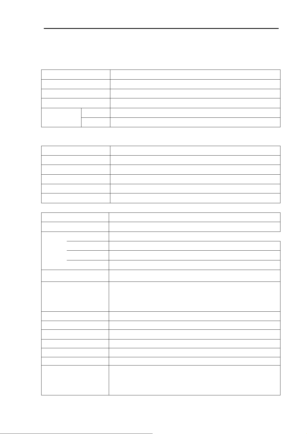
2.1 Standard equipment list
No.
Item Type name Remarks
KGP-925.MU
With mounting bracket and vinyl cover
01 Display unit
KGP-925.MUD
02 Antenna unit
MA-620G
03 DC power cable CW-266-1.8M
04 Connector CBD-L206SA
05 Connector CBD-L208SA
Truss tapping screw
06
07 Operation manual
TPT5X20U
KGP-925.OM.E
With mounting bracket and vinyl cover
TNC(M)+10mRG58+BNC(M)
With 3-pin connector, other end
plain
6 pin water resistant connector
8 pin water resistant connector
For mounting bracket -- 2
English 1
2.2 Optional items list
No.
01 CW-373-5M
Connecting cable
02 CW-376-5M
03
04 Junction box JB-10
Item Type name Remarks
6 pin water resistant connectors both
ends
A 6 pin water resistant connector and
other end plain
CW-391-1-5M
A 8 pin water resistant connector and
other end plain w / EMI core
1 input,3 outputs X 2 circuits
Weight/Length
0.86kg
0.95kg
0.18kg
Without cable
1.8m
--
-- 1
Weight/
Length
0.4kg
Q’ty
1
1
1
1
5m
5m
5m
05 Power rectifier PS-010
06 AC power cable VV-2D8-3M
07 Flush mount kit FMK-1
Internal beacon receiver kit
08
Beacon antenna
09
coupler
INT-DGPS KIT
BA-02L-K
10 Whip antenna *BA-03(RA-14)
Operation manual
11
Service manual
12
KGP-925.OM.E
KGP-925.SM.E
With 5A fuses 2pcs
For PS-010, both ends plain
Flush mount frame with bolts, washers
and screws
Receiver PCB, connector, harness
(install at the factory)
For beacon reception, with antenna
cable. Connected to BA-02L/BNC
connector.
2.45m, for BA-02
English
English
3.5kg
3m
--
1.2kg
15m
0.3kg
*About Whip antenna: BA-03 is a name in the MT Electronics LLC, but RA-14 is a name in the KODEN
Electronics Co.,Ltd.
0093192502-01 2-1

KGP-925 Chapter 3 Specifications
Chapter 3 Specifications
Page No.
3.1 GPS/GLONASS receiver section ............................................................3-1
3.2 Beacon receiver section (Internal beacon receiver type only) ............3-1
3.3 Display section ........................................................................................ 3-1
3.4 Data Input/Output.....................................................................................3-2
3.5 Power requirements ................................................................................3-2
3.6 Compass safe distance...........................................................................3-2
3.7 Environmental conditions.......................................................................3-2
3.8 External dimensions and weight............................................................3-3
0093192502-01 Contents
KGP-925 Chapter 3 Specifications
Chapter 3 Specifications
3.1 GPS/GLONASS receiver section
Receiving frequency 1575.42 MHz(GPS) 1597.5 - 1609.5MHz(GLONASS)
Receiving channel
Satellite access mode All-in-view
Sensitivity
Accuracy
Note: Accuracy is subject to change in accordance with DoD civil GPS user policy.
Position
Velocities 0.1 kt rms
32 channel parallel
-160dBm(tracking and reacquisition) -143dBm(acquisition)
2.5m RMS(autonomous), 1m RMS(differential)
3.2 Beacon receiver section (Internal beacon receiver type only)
Receiving frequency 283.5 to 325.0kHz
Channel separation
Modulation MSK: 50, 100, 200bit/sec.
Sensitivity
Signal detection (S/N)
Dynamic range 92dB
500Hz step
2.5uV/m or less
Better than 6 dB
3.3 Display section
Display
LCD with backlight (128 x 64 dot’s, effective picture area: 85.71 x 54.35 mm)
Display mode NAV1, NAV2, NAV3, PLOT, MOB (Man Over Board)
Track
display
Position data display
Navigational display
Instant (event) memory
Waypoint memory
Route memory 20 routes (Max. 400 waypoints) reverse trail possible
Alarm Proximity, cross track error, CDI, anchor watch
Position compensation Latitude/longitude, LOPs, Datum
Magnetic compensation Auto or manual
Parameters
Display range
Usable ground
Plotting interval
Plotting capacity
0.025, 0.05, 0.1, 0.2, 0.5, 1, 2, 5, 10, 20 nm (sm, km)
Within 80° in latitude
10, 20, 30 seconds, 1, 3, 5 minutes, 0.1, 0.5, 1 nm (sm, km)
2,000 points
Latitude/longitude in increments of 0.0001 minute, converted Loran C
LOPs, converted Loran A LOPs, converted Decca LOPs,
Speed, course, velocity made good/course made good/elapsed time,
altitude, distance/bearing/cross track error/course deviation/time to go to
waypoint, total time to go and distance on route, DOP value, present time
(UTC or LTC), satellite status, beacon receiving status, distance/bearing
between two points, MOB display
200 points
200 points
Loran C LOPs conversion, Loran A LOPs conversion, Decca LOPs
conversion, memory of waypoints and name (up to 10 letters), selection
of measuring unit (nm, sm, km), antenna height unit (ft, m), antenna
height, averaging (smooth) factor, position mode (2D or 3D automatic
selection), beacon stations selection
0093192502-01 3-1

Chapter 3 Specifications KGP-925
3.4 Data Input/Output
Output data format
(DATA connector)
Output data format
(DATA2 conn ector)
IEC 61162-1/ NMEA 0183 Ver.1.5 (NMEA1, 2)/ CIF/ SHIPMATE
(AAM, APB, BOD, BWC, DCN, DTM, GBS, GGA, GLC, GLL, GNS, GSA, GSV,
MSS, RMB, RMC, Rnn, RTE, SGR, VTG, WDC, WPL, XTE, ZDA)
IEC 61162-1
(AAM, APB, BOD, BWC, DCN, DTM, GBS, GGA, GLC, GLL, GNS, GSA, GSV,
MSS, RMB, RMC, Rnn, RTE, SGR, VTG, WDC, WPL, XTE, ZDA)
3.5 Power requirements
Input voltage: 10.8 - 31.2 VDC
Power consumption: Less than 4.0 W (at 24VDC)
Less than 4.5 W (at 24VDC) : Internal beacon receiver type
AC Operation: AC/DC rectifier P
Input voltage range:
S-010 is required.
115 VAC
or
230 VAC
3.6 Compass safe distance
Standard: 0.8m
Steering: 0.4m
3.7 Environmental conditions
(1) Temperature and humidity
Operating temperature
Humidity 93% (+40°C)
(2) Vibration
The equipment operates normally under the following vibrating conditions.
2 - 5 Hz - 13.2 Hz: Amplitude ±1mm ±10 % (Maximum acceleration of 7 m/s
13.2 Hz - 100 Hz: Maximum acceleration of 7 m/s
Display unit: - 15° to + 55°C
Antenna unit: - 40° to + 85°C
2
being applied
2
at 13.2 Hz)
(3) Water proof
Display unit: IPX4
Antenna unit: IPX6
3-2 0093192502-01
KGP-925 Chapter 3 Specifications
g
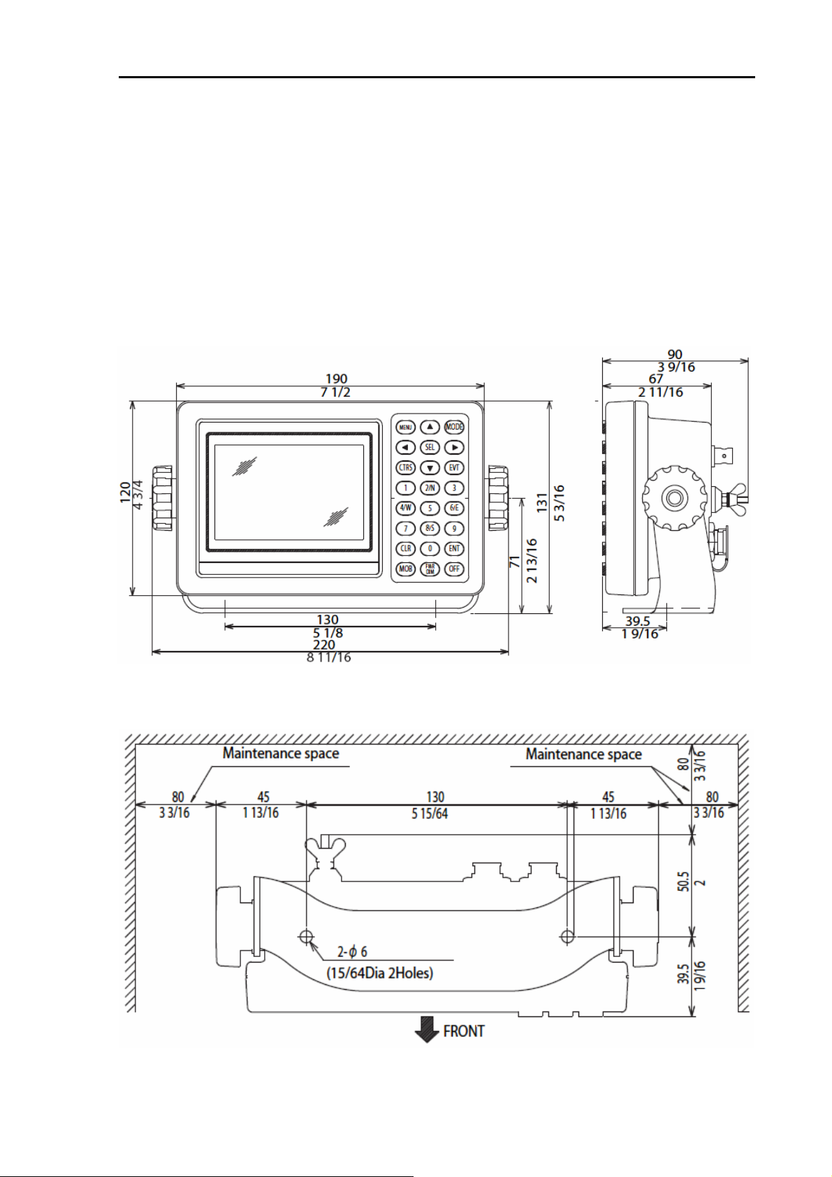
3.8 External dimensions and weight
External dimensions: Width x Height x Depth
Dimensions (WxHxD): 220 x 131 x 90 (mm)
Weight: 0.86 kg / 0.95kg (Internal beacon receiver type)
Refer to Figure 3.1 for the exterior with dimensions.
Refer to Figure 3.2 for service space required.
Refer to Figure 3.3 for exterior of antenna unit with dimensions.
Refer to Figure 3.4 for exterior of beacon antenna coupler with dimensions. (Internal bea con re ceiver
type only)
Figure 3.1 The Exterior of KGP-925 with dimensions
Unit: mm (inch)
0093192502-01 3-3
Fi
ure 3.2 Service space required for KGP-925
Unit: mm (inch)
Chapter 3 Specifications KGP-925
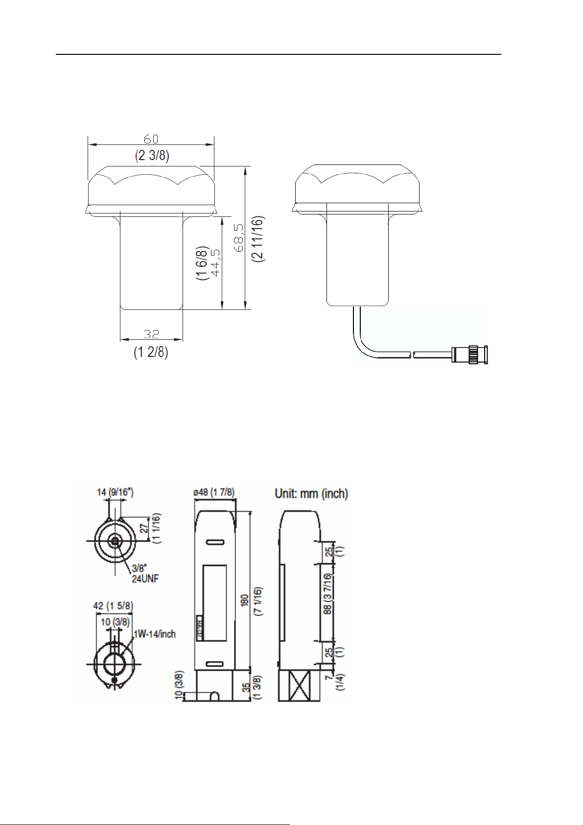
MA-620G: with cable (10m)
Unit: mm (inch)
Weight
Without cable : 0.18kg
BA-02L-K : with cable (15m)
Figure 3.3 The Exterior of antenna unit with dimensions
Weight
Without cable : 0.4kg
Figure 3.4 The Exterior of beacon antenna coupler with dimensions (Option)
3-4 0093192502-01

KGP-925 Chapter 4 Installation
Chapter 4 Installation
Page No.
4.1 Installation consideration .......................................................................4-1
4.2 Unpacking of the goods .......................................................................... 4-1
4.3 Inspection of the goods ..........................................................................4-1
4.4 Siting the units.........................................................................................4-1
4.5 Display unit installation...........................................................................4-1
4.5.1 Table mounting................................................................................................4-1
4.5.2 Flush mounting................................................................................................4-3
4.6 Antenna unit installation.........................................................................4-4
4.6.1 Selecting the best site of GPS/ GLONASS and beacon antenna units........4-4
4.6.2 Fixing the GPS/ GLONASS antenna unit........................................................4-5
4.6.3 Fixing the beacon antenna coupler and receiving antenna (internal beacon
receiver type only)..........................................................................................4-5
4.7 Cable connections to KGP-925...............................................................4-6
4.7.1 Single connection............................................................................................4-6
4.7.2 Multi connections............................................................................................4-7
4.8 Connector pin outs..................................................................................4-8
4.9 Inspection after installation ....................................................................4-9
0093192502-01 Contents

KGP-925 Chapter 4 Installation
Chapter 4 Installation
4.1 Installation consideration
General
Qualified service technicians should perform the installation of the KGP-925 that comprises the
following operations.
(1) Unpacking each component of the system.
(2) Inspection of the exterior of each component unit and accessory.
(3) Checking the ship’s mains voltage and current capacit y.
(4) Determining the installation site
(5) Installing the Display unit
(6) Planning the cable routing and connections
(7) Adjustment and setups
4.2 Unpacking of the goods
Unpack your package and check if all of the items stated in the packing list are contained in the
package. If not, report this to an insurance agent for tracing missing good s or refund.
4.3 Inspection of the goods
Carefully check the exterior of each component unit for dents, damage, etc. Also check the inside of
component units for electrical and mechanical damages.
4.4 Siting the units
To achieve best operational performance, the following factors must be considered.
(1) The display unit should be positioned in the location where the external situation can be viewed.
(2) Locate the display so that it provides easy viewing from all likely operator’s positions.
(3) Select a position safe and free from dampness, water spray, rain and direct sunlight.
(4) Provide enough space for servicing. Consider access to the rear panel for connecting cables.
(5) Position the display unit as possible away from other radio equipment.
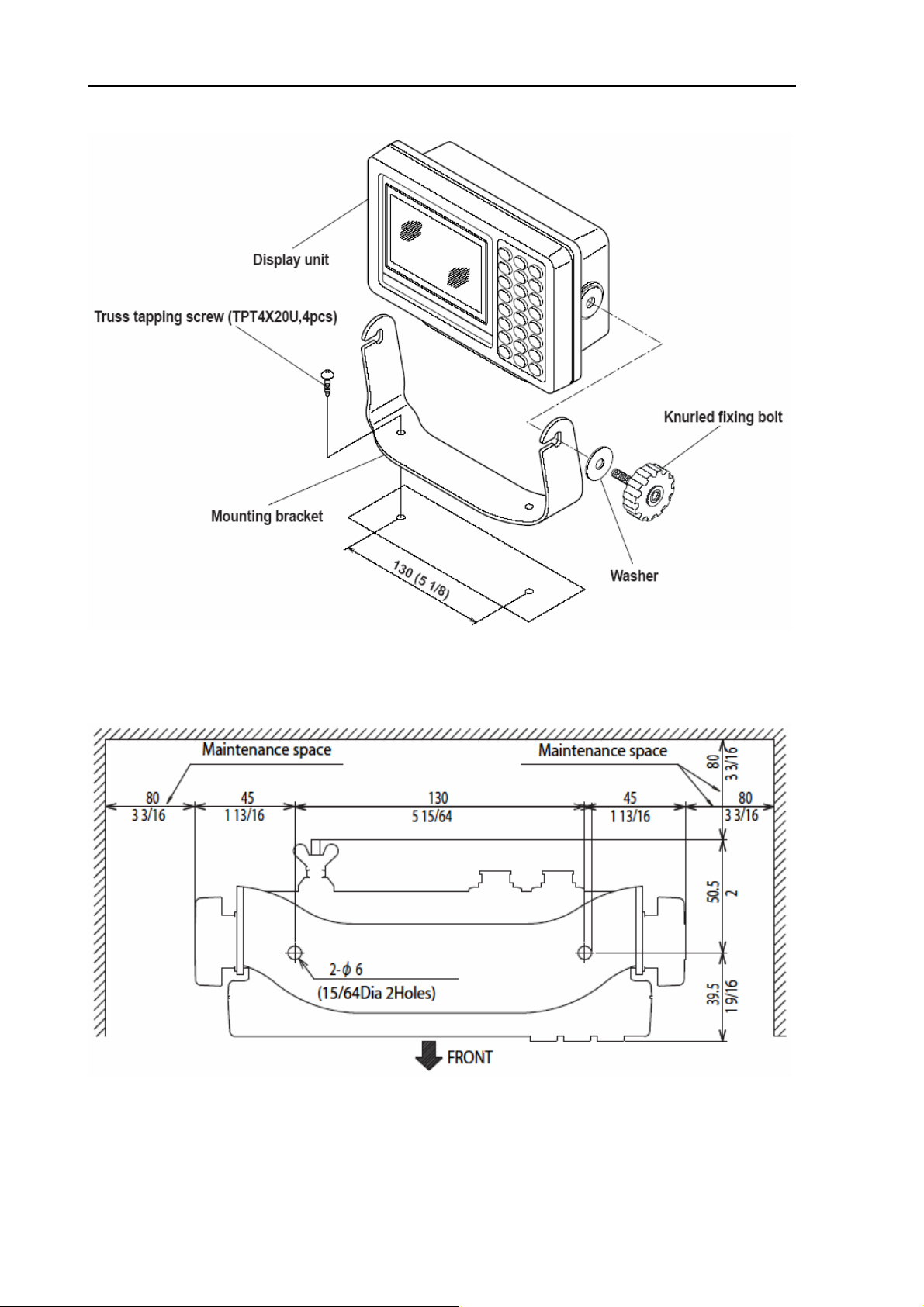
4.5 Display unit installation
The display unit is designed for table mount and flush mount. Refer to Figure 4.1or 4.3 for installation.
4.5.1 Table mounting
(1) Remove the two knurled fixing knobs that fix the display unit to the mounting bracket.
(2) Remove the display unit from the bracket and place it on a flat and safe area.
(3) Place the mounting bracket to the place where the display unit is to be installed, and fix the bracket
with two (2) tapping screws.
(4) Reset the display unit on to the bracket and fix it using the two knurled fixing knobs that were
removed in step (1). Refer to Figure 4.2 for detail.
0093192502-01 4-1
Chapter 4 Installation KGP-925
Figure 4.1 Fitting detail of KGP-925 in table mounting mode
4-2 0093192502-01
Figure 4.2 Service space required for KGP-925
Unit: mm (inch)

KGP-925 Chapter 4 Installation
4.5.2 Flush mounting
(1) Cut a rectangle opening as shown in a figure4.3.
(2) Loosen two (2) fixing knobs that fasten the display unit onto the mounting bracket.
(3) Put the display on the flush mount and fix with two (2)slotted –head screws.
(4) Put the display on the opening and fix with four (4) tapping screws. In case you use M4 screws to
fix the display, select an appropriate screw length that best suits fixing the unit to the panel
thickness.
Figure 4.3 Fitting KGP-925 in flush mounting mode
Unit: mm (inch)
0093192502-01 4-3
Chapter 4 Installation KGP-925
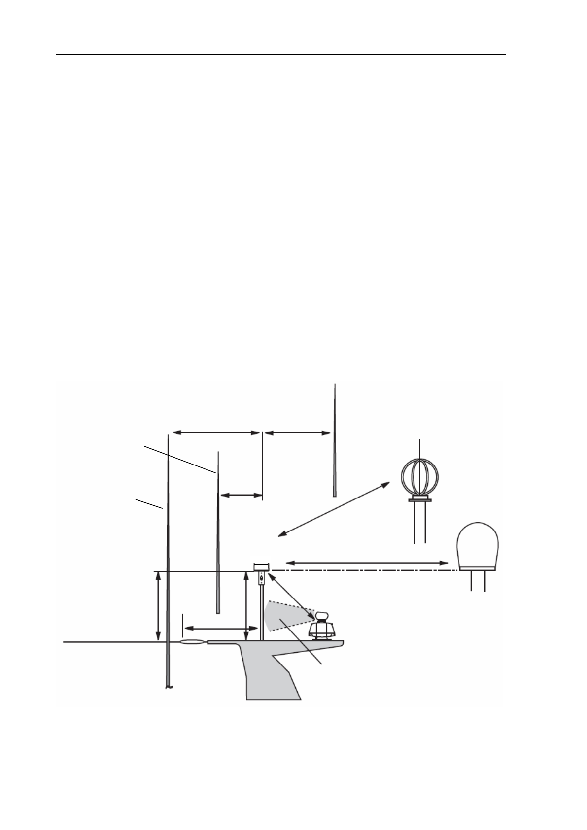
4.6 Antenna unit installation
4.6.1 Selecting the best site of GPS / GLONASS and beacon antenna units
Make sure to install the antenna unit at a location where nothing shades the antenna of a view above
the horizon. Objects placed above the antenna unit or too close to the antenna unit may cause signal to
noise ratio to degrade and shorten measuring time.
(1) As far away from any metallic objects as possible.
(2) At least 4 meters (13.2 feet) away from the MF/HF reversed L-type TX antenna, VHF or HF whip
antenna.
(3) At least 1.5 meter (4.9 feet) above the MF/HF reversed L-type TX antenna.
(4) At least 1 meter (3.3 feet) away from the receiving antenna.
(5) Outside radar transmitting beam (30° to 40°).
(6) At least 1 meter (3.3 feet) away from the radar antenna.
(7) At least 5 meters (16.5 feet) away from the Inmarsat antenna.
(8) At least 3 meters (9.8 feet) away from the loop antenna.
(9) At least 0.5 meters (1.6 feet) above the large metal surface.
4 m (13.2 ft) or more 4 m (13.2 ft) or more
Receiving antenna
HF whip antenna
1.5 m (4.9 ft) or more
MF/HF reversed
L-type TX antenna
4 m (13.2 ft) or
1 m (3.3 ft)
Antenna/Antenna coupler
MA-620G/BA-02L-K
more
3 m (9.8 ft) or more Or more
Outside the radar beam
o
to 40o
30
VHF whip antenna
LOOP antenna
Inmarsat antenna
5 m (16.5 ft) or more
Main beam
Figure. 4.4 Recommended Antenna (MA-620G/BA-02L-K) installation
* AT least 0.5 m (1.6 ft) above the large metal surface
4-4 0093192502-01
KGP-925 Chapter 4 Installation
(Op
(Op
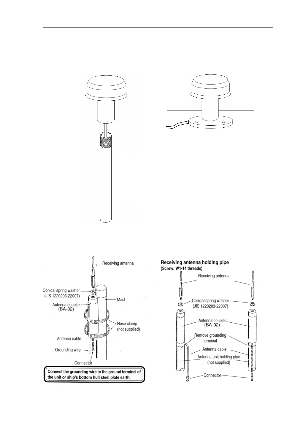
4.6.2 Fixing the GPS/GLONASS antenna unit
(Case1) (Case2)
Antenna unit
MA-620G
Antenna unit
MA-620G
Screw
(1”-14UNS-2B)
Antenna
extension pole
(not supplied)
Roof top
FB1
Base
mounting
4.6.3 Fixing the beacon antenna coupler and receiving antenna (Internal beacon
receiver type only)
(Case1)
(Case2)
BA-03(*RA-14)
tion)
*RA-14 is a name in the KODEN
BA-03(*RA-14)
tion)
0093192502-01 4-5
Chapter 4 Installation KGP-925
)
A
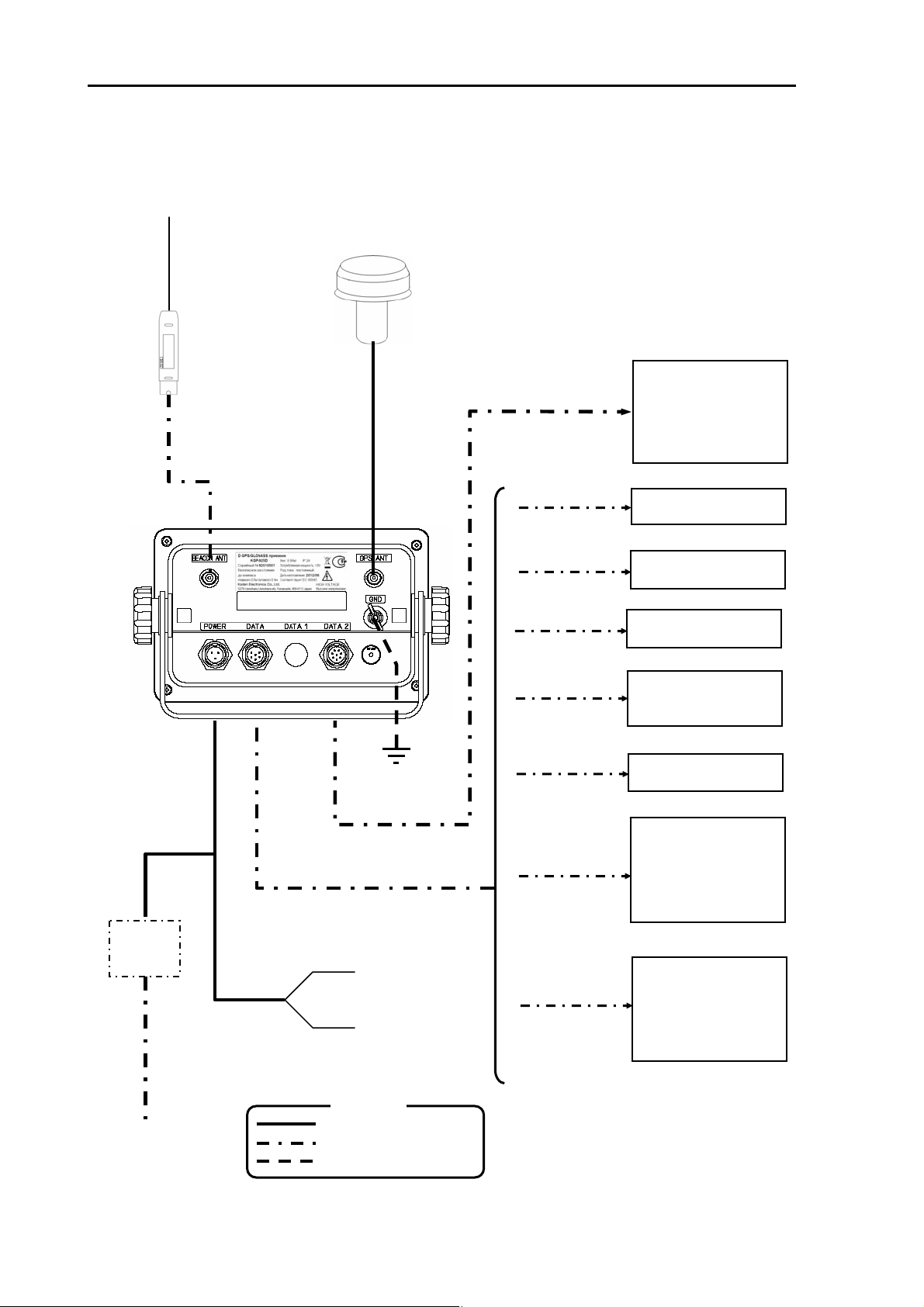
4.7 Cable connections to KGP-925
4.7.1 Single connection
*RA-14 is a name in the KODEN
Whip antenna
BA-03(*RA-14)
(Option)
Antenna unit
MA-620G
Beacon antenna
BA-02L-K(Option)
DC Power cable
CW-266-1.8M
Power
rectifier
PS-010
100/115VAC
200/230VAC
AC Power cable
VV-2D8-3M
(Option)
coupler
Grounding
Wire
(not supplied)
+ (Red
10.8 to 31.2VDC
- (Black)
Legend
Standard configuration
Option
Prepared by a customer
CW-391-1-5M
CW-373-5M
CW-373-5M
CW-373-5M
CW-376-5M
Use the cable
ttached to CVS
CW-373-5M
CW-376-5M
Chart plotter
Marine radar
Echo sounder
Auto pilot
AIS
(Other brand)
Chart plotter
GTD-110/150
Plotter sounder
CVG-80/200
Echo sounder
CVS-841/852series
Echo sounder
CVS-1410series
CVS-FX series
Echo sounder
CVS-126/128
Marine radar
MDC-900series
MDC-2000series
MDC-2200series
MDC-2500series
MDC-2900series
Chart plotter
Marine radar
Echo sounder
Auto pilot
AIS
(Other brand)
4-6 0093192502-01
KGP-925 Chapter 4 Installation
)
A
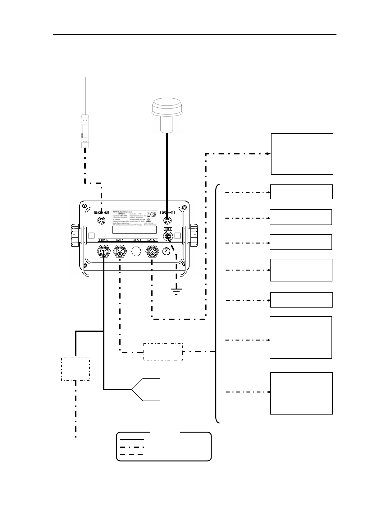
4.7.2 Multi connections
*RA-14 is a name in the KODEN
Whip antenna
BA-03(*RA-14)
(Option)
Antenna unit
MA-620G
Beacon antenna
BA-02L-K(Option)
DC Power cable
CW-266-1.8M
Power
rectifier
PS-010
100/115VAC
200/230VAC
AC Power cable
VV-2D8-3M
(Option)
coupler
CW-376-5M
Junction Box
Standard configuration
Option
Prepared by a customer
Grounding
Wire
(not supplied)
JB-10
+ (Red
10.8 to 31.2VDC
- (Black)
Legend
CW-391-1-5M
CW-376-5M
CW-376-5M
CW-376-5M
CW-376-5M
Use the cable
ttached to CVS
CW-376-5M
Customer’s supply
Chart plotter
Marine radar
Echo sounder
Auto pilot
AIS
(Other brand)
Chart plotter
GTD-110/150
Plotter sounder
CVG-80/200
Echo sounder
CVS-841/852series
Echo sounder
CVS-1410series
CVS-FX series
Echo sounder
CVS-126/128
Marine radar
MDC-900series
MDC-2000series
MDC-2200series
MDC-2500series
MDC-2900series
Chart plotter
Marine radar
Echo sounder
Auto pilot
AIS
(Other brand)
0093192502-01 4-7
Chapter 4 Installation KGP-925
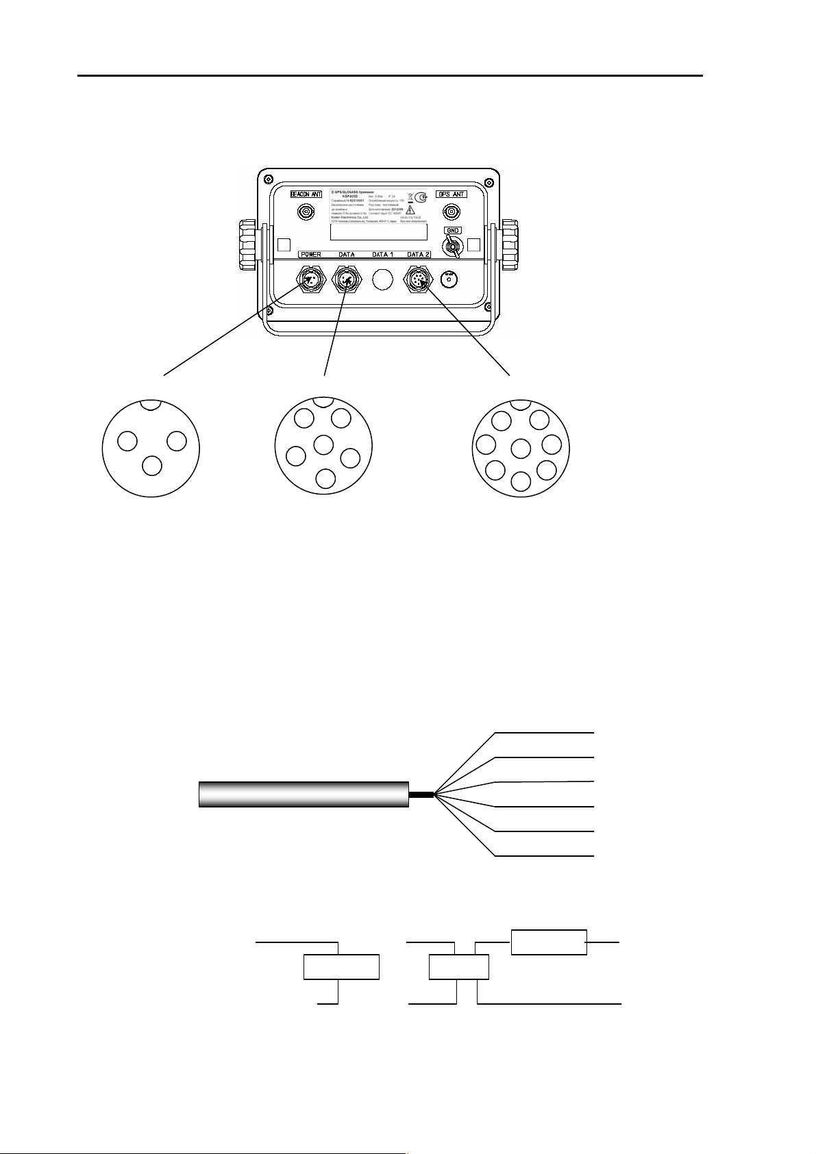
4.8 Connector pin outs
POWER
1 3
2
1: DC +
2: F.GND
3: DC -
DATA
1 5
6
2
3
1: GND/SHIELD
2: TXD (+)
3: TXD (-)
4: RXD (+)
4
5: RXD (-)
6: +15V
(General data output)
* RXD is used only
maintenance
(CW-376-5M, CW-391- 1-5M Pin number form cable side )
These cables are used as a general/extension data port and
external DGPS beacon receiver.
To display unit
DA TA 2
7
1
8
3
4
(External beacon receiver)
See page 8-19
(Extension data output)
(External buzzer)
2:ACK/ALARM OUT(+)
3:ACK/ ALARM OUT(-)
*When ACK/ ALARM Mode is ON
Blue
White
Red
Orange
Black
Green
1: GND/SHIELD
2: TXD (+)
3: TXD (-)
4: RXD (+)
6 2
5: RXD (-)
6: BUZZER STP(+)
5
7: BUZZER STP(-)
8: EXT BUZZER
GND
TXD (+)
TXD (-)
RXD (+)
RXD (-)
+15V
(External buzzer connection)
DATA No.6pin: +15V
DATA 2 No.8pin: EXT BUZZER
Buzzer
or
Buzzer
Relay
(+)
(-)
4-8 0093192502-01
KGP-925 Chapter 4 Installation
(DATA port)
This port is general data output port. Output data is selected by the menu among the output of
IEC 61162-1, NMEA Ver.1.5, CIF, and SHIPMATE. Output signal level is RS-422.
(DATA 2 port)
When CW-376/391 is used.
This port is data input/output port for DGPS beacon receiver. If a DGPS receiver is not connected,
it can be used as a data output port for extension, but unlike the DATA port, output is possible only
for IEC 61162-1. Output signal level is RS-422.
When CW-398 is used.
This port is an only for external alarm system. ACK/ALARM output signal level is RS-422, and EXT
BUZZER out put can drive a relay (24V/10mA). BUZZER STP is an input port for stopping a buzzer ,
and impresses 24V.
NOTE: ACK/ALARM of menu 9-3 needs to be turned off. See chap ter 8.6.5 (pag e 8-18)
NOTE: ACK/ALARM of menu 9-3 needs to be turned on. See chap ter 8.6.5 (p age 8-1 8)
4.9 Inspection after installation
Before you turn the unit on, check the following points to make sure the system operates properly.
(1) Is the ship’s supply voltage and current within the rated range?
(2) Is the connection between the display and antenna unit correct?
(3) Are the cables routed and connected properly?
0093192502-01 4-9
 Loading...