

Page 1
Page 2

Page 3

KGP-915 Revision History
KGP-915 Operation Manual
Doc No: 0093129152
Document Revision History
No. Doc. No-Rev. No.
0 0093129152-00 2016/12/28 First edition
1
2
3
4
5
6
7
Date revised
Revised content
(Y/M/D)
8
9
10
Document No. Revised Version Norm
When part of the document needs to be revised, the document has advanced revision number.
The document No. is indicated at the lower right side on the cover and at the left or right side of the
footer region of each page.
© 2016 Koden Electronics Co., Ltd. All rights reserved.
No part of this publication may be reproduced, transmitted, translated in any form by any means without
the written permission of Koden Electronics Co., Ltd. The technical descriptions contained in this
publication are subject to change without notice. Koden assumes no responsibility for any errors,
incidentals or consequential damages caused by misinterpretation of the descriptions contained in this
publication.
0093129152-00 i
Page 4

Important Notice KGP-915
Important Notice
For copy and transcription of this Operation Manual (hereinafter referred to as this
manual), permission from Koden is needed. Koden prohibits the un-authorized copy and
transcription of this manual.
If this manual is lost or damaged, consult a dealer of Koden or Koden.
The specification of the products and the contents in this manual are subject to change
without notice.
The contents displayed on the menu of product may be different from the expression of
this manual. The fonts and shapes of the keys and menus in the illustration may differ
from the actual ones, and some parts may be omitted.
Koden is not liable for damages and troubles arisen from misunderstanding of the
contents in this manual.
Koden is not liable for any damages caused by earthquake, lightning, wind and flood
damage and fire for which Koden is not responsible, and actions by third parties, other
accidents, customer’s unintended error/abuse and the use under other abnormal
conditions.
Koden is not liable for damages of accompaniment (change/loss of memorized content,
loss of business profit, stop of business) arisen from use or failure of our products.
If the stored data are changed or lost, irrespective of causes of troubles and damages,
Koden is not liable for them.
Koden is not liable for any damages arisen from malfunction caused by combination of
software and connected equipment in which Koden is not engaged.
ii 0093129152-00
Page 5
KGP-915 For Your Safe Operation
For Your Safe Operation
Symbol used in this Operation Manual
The following pictograms are used in this manual. The meaning of each symbols shall be well
understood and the maintenance and inspection shall be carried out.
Symbol Meaning
Mark for warning
Warning
This mark denotes that there is a risk of death or serious injury when
dealt with incorrectly.
Mark for danger of high voltage
This mark denotes that there is a risk of death or serious injury due to
electric shock when dealt with incorrectly.
Mark for caution
Caution
This mark denotes that there is a risk of slight injury or damages of
devices when dealt with incorrectly.
Mark for prohibition
This mark denotes prohibition of specified conducts. Description of the
prohibition is displayed near the mark.
Precautions on equipment
Be careful of high voltage inside
High voltage, which may risk you life, is used. This high voltage may
remain in the circuit even after the power is switched off. To prevent
contact with the high voltage circuits accidentally, a protective cover or
the label with this mark is provided on the high voltage circuit. When the
inside is to be checked, ensure to switch off the power and to discharge
the residual voltage for safety. An engineer authorized by Koden shall
carry out the inspection and maintenance works.
Power off in the boat
Warning
An accidental power-on during works may result in worker’s
electrification. To prevent such accident in advance, ensure that power
in the boat and on the equipment are switched off. Furthermore, it is
safer to hang a caution tag saying “Under work” near the power switch
of equipment.
Be careful of dust
Warning
Inhaled dust may cause respiratory affection. At the time of cleaning the
inside of equipment, be careful not to inhale dust. Wearing a safety
mask is recommended.
Caution on location of installment
Caution
The equipment shall not be installed at locations which are excessively
damp and suffers from water drops. Otherwise, dew condensation may
occur inside the display screen, and corrosion may occur inside the unit
box.
0093129152-00 iii
Page 6
For Your Safe Operation KGP-915
Measures against static electricity
Caution
Precautions on handling
Warning
Warning
Caution
Static electricity may be generated from the carpet on the floor in the
cabin or clothes made of synthetic fiber, and it may destroy the
electronic components on circuit boards. The circuit boards shall be
handled with appropriate measures against static electricity.
No disassembly or modification of this equipment is allowed. It may lead
to failure, firing, smoking or electric shock. In case of failure, please
contact Koden’s dealers or Koden.
In case of smoking or firing, switch off the power in the boat and of this
equipment. It may lead to firing, electric shock or damages.
Be careful of residual high voltage
High voltage may remain in capacitors for several minutes after
switching off the power. Before inspection of the inside, please wait at
least 5 minutes after switching off or discharge the residual electricity in
an appropriate manner. Then, start the work.
The information displayed on this equipment is not intended to use for
your navigation. For your navigation, be sure to see the specified
materials.
iv 0093129152-00
Page 7

KGP-915 Contents
Contents
Document Revision History .................................................................................................................. i
Important Notice .................................................................................................................................. ii
For Your Safe Operation .................................................................................................................... iii
Contents .............................................................................................................................................. v
Introduction .......................................................................................................................................... x
System Configuration ......................................................................................................................... xi
System Configuration (with Junction box) ......................................................................................... xii
Configuration of Equipment .............................................................................................................. xiv
Chapter 1 Basic Operation ................................................................................1-1
1.1 The name and function of each part ......................................................................................... 1-1
1.1.1 Control panel ................................................................................................................ 1-1
1.2 Power On/Off ............................................................................................................................ 1-2
1.3 Adjusting brightness of display and panel key .......................................................................... 1-2
1.4 Selecting the screen ................................................................................................................. 1-3
1.4.1 Display Modes ............................................................................................................ 1-3
1.4.2 Nav data display1 (NAV1) screen : Nav data1 mode .................................................. 1-3
1.4.3 Nav data display2 (NAV2) screen : Nav data2 mode .................................................. 1-4
1.4.4 Nav data display3(NAV3) screen : Nav data3 mode ................................................... 1-4
1.4.5 Navigation Graph display (NAV4) screen : Navigation Graph mode ........................... 1-4
1.4.6 Highway display (NAV5) screen : Highway mode ........................................................ 1-5
1.4.7 Plotter display (NAV6) screen : Plotter mode .............................................................. 1-5
1.5 Storing present position (EVENT) ............................................................................................. 1-6
1.5.1 AUTO ........................................................................................................................... 1-6
1.5.2 MANUAL ...................................................................................................................... 1-6
1.5.3 Changing the setup contents ....................................................................................... 1-7
1.6 Using POB (People over-board) ............................................................................................... 1-8
1.7 Recalling Event and POB position ............................................................................................ 1-8
1.8 Copying Event and POB position ............................................................................................. 1-9
1.8.1 Erasing Event and POB position ................................................................................. 1-9
Chapter 2 Various Navigation ............................................................................2-1
2.1 Storing waypoints (LAT/LONG) data ......................................................................................... 2-1
2.1.1 Storing a new waypoint or updating an existing a waypoint ........................................ 2-1
2.1.2 Copying a position ....................................................................................................... 2-3
2.1.3 Erasing a single waypoint ............................................................................................ 2-3
2.2 Setup of waypoint navigation .................................................................................................... 2-4
2.2.1 Setting waypoint navigation ......................................................................................... 2-4
0093129152-00 v
Page 8

Contents KGP-915
2.2.2 Quick waypoint setup ................................................................................................... 2-4
2.2.3 Canceling waypoint navigation .................................................................................... 2-5
2.2.4 NAV2 screen during waypoint navigation .................................................................... 2-6
2.2.5 NAV3 screen during waypoint navigation .................................................................... 2-6
2.2.6 NAV4 screen during waypoint navigation .................................................................... 2-7
2.2.7 NAV5 screen during waypoint navigation .................................................................... 2-7
2.2.8 NAV6 screen during waypoint navigation .................................................................... 2-8
2.3 Cross track error and course deviation angle ........................................................................... 2-9
2.3.1 Navigation graph of NAV4 screen ................................................................................ 2-9
2.3.2 Highway display (NAV5) screen ................................................................................. 2-10
2.4 Storing and erasing routes ...................................................................................................... 2-12
2.4.1 Storing your route ....................................................................................................... 2-12
2.4.2 Automatic switching of waypoints .............................................................................. 2-13
2.4.3 Copying a single route ............................................................................................... 2-13
2.4.4 Erasing point data ...................................................................................................... 2-14
2.4.5 Erasing a single route ................................................................................................ 2-14
2.5 Route setup ............................................................................................................................. 2-15
2.5.1 Selecting route navigation .......................................................................................... 2-15
2.5.2 Checking a route point position .................................................................................. 2-16
2.5.3 Canceling route navigation ......................................................................................... 2-17
2.5.4 Switching between distance and time to go ............................................................... 2-17
2.6 Setting an anchor position ....................................................................................................... 2-19
2.6.1 Storing an anchor position.......................................................................................... 2-19
2.6.2 Canceling anchor position .......................................................................................... 2-20
2.7 Track display ........................................................................................................................... 2-21
2.7.1 Display a cross cursor on NAV6 screen ..................................................................... 2-21
2.7.2 Screen scrolling .......................................................................................................... 2-22
2.7.3 Scaling the PLOT screen ........................................................................................... 2-22
2.7.4 Changing the setup contents ..................................................................................... 2-22
Chapter 3 Alarms .............................................................................................. 3-1
3.1 Kinds of alarms .......................................................................................................................... 3-1
3.1.1 GNSS Fix ..................................................................................................................... 3-1
3.1.2 Anchor watch alarm (ANCH) ........................................................................................ 3-1
3.1.3 Proximity alarm (PROX) ............................................................................................... 3-2
3.1.4 Cross track error alarm (XTE) ...................................................................................... 3-2
3.1.5 Course deviation angle alarm (CDI) ............................................................................. 3-3
3.2 Alarm explanation ...................................................................................................................... 3-3
3.3 Setting and canceling ................................................................................................................ 3-3
vi 0093129152-00
Page 9

KGP-915 Contents
Chapter 4 Setup Procedure ...............................................................................4-1
4.1 Menu options............................................................................................................................. 4-1
4.2 Menu 3: GNSS .......................................................................................................................... 4-4
4.2.1 Monitoring GNSS satellite signal reception ................................................................. 4-4
4.2.2 Selecting a GNSS mode .............................................................................................. 4-4
4.2.3 Selecting a geodetic datum ......................................................................................... 4-5
4.2.4 Setting the mask level of carrier-to-noise ratio ............................................................ 4-5
4.2.5 Masking satellite elevation angle ................................................................................. 4-6
4.3 Menu 4: Differential GNSS(DGNSS) ........................................................................................ 4-7
4.3.1 Displaying DGNSS ....................................................................................................... 4-7
4.3.2 Selecting a style of DGNSS ......................................................................................... 4-7
4.3.3 Setting a DGNSS timeout ............................................................................................ 4-8
4.3.4 Selecting a SBAS station ............................................................................................. 4-8
4.3.5 Selecting a beacon station (Beacon DGNSS only) ..................................................... 4-9
4.3.6 Setting receiving frequency and bit rate of a beacon station ....................................... 4-9
4.3.7 Selecting the DGNSS input signal baud rate ............................................................. 4-10
4.3.8 Beacon monitor ...........................................................................................................4-11
4.4 Menu 5: Compensation ........................................................................................................... 4-12
4.4.1 Correcting your position ............................................................................................. 4-12
4.4.2 Disable position correction ......................................................................................... 4-13
4.4.3 Compensating the LOP.............................................................................................. 4-13
4.4.4 Compensating the compass ...................................................................................... 4-15
4.4.5 Displaying local time .................................................................................................. 4-16
4.5 Menu 7: Calculation ................................................................................................................ 4-17
4.5.1 Calculating the distance and bearing between two points ......................................... 4-17
4.5.2 Calculating LOPs based on LAT/LONG data ............................................................. 4-17
4.5.3 Calculating navigation plan ........................................................................................ 4-20
4.6 Menu 8: Initial setup ................................................................................................................ 4-23
4.6.1Setting average constants(measuring position, speed and course) ............................. 4-23
4.6.2Changing the distance or speed unit ............................................................................. 4-23
4.6.3Changing sail mode ....................................................................................................... 4-24
4.6.4Displaying position data in LAT/LONG mode ................................................................ 4-24
4.6.5Changing the latitude and longitudinal display digits .................................................... 4-25
4.6.6Selecting GNSS source ................................................................................................. 4-25
4.6.7Selecting a Language .................................................................................................... 4-26
4.6.8Specifying the chain and secondary stations for Loran C, Loran A or Decca ............... 4-26
4.7 Menu 9: Interface .................................................................................................................... 4-28
4.7.1 Selecting a DATA port to setting. ............................................................................... 4-28
4.7.2 Selecting an output data format of DATA1 and DATA2 port ...................................... 4-28
0093129152-00 vii
Page 10

Contents KGP-915
4.7.3 Setting the Baud rate ................................................................................................. 4-29
4.7.4 Setting the output Talker ID ........................................................................................ 4-30
4.7.5 Selecting an output sentence ..................................................................................... 4-30
Chapter 5 How to use LOPs ............................................................................. 5-1
5.1 Initial setup for LOPs display ..................................................................................................... 5-1
5.1.1 Selecting LOP (Loran C, Loran A or DECCA) .............................................................. 5-1
5.2 Storing waypoints (LOPs data) .................................................................................................. 5-4
5.2.1 Storing a new position or updating an existing one ..................................................... 5-4
5.3 Compensating the LOP ............................................................................................................. 5-5
5.4 Calculating LOPs based on LAT/LONG data ............................................................................ 5-5
Chapter 6 Data backup and initialization ........................................................... 6-1
6.1 Data backup .............................................................................................................................. 6-1
6.1.1 Displaying the “Data backup” menu ............................................................................. 6-1
6.1.2 Insert USB memory ...................................................................................................... 6-1
6.1.3 Read out of data ........................................................................................................... 6-1
6.1.4 Writing of data .............................................................................................................. 6-2
6.2 Initialization ................................................................................................................................ 6-4
6.2.1 Displaying the “Initial menu” ......................................................................................... 6-4
6.2.2 Initialize ........................................................................................................................ 6-4
6.2.3 WPT./Route clear ......................................................................................................... 6-5
6.2.4 Changing a storing method for present position (Event) ............................................. 6-5
6.2.5 Selecting an initial value (North, South, East, West) of latitude/longitude. .................. 6-6
6.2.6 Frequency adjustment of the buzzer ............................................................................ 6-6
Chapter 7 Installation ........................................................................................ 7-1
7.1 Installation consideration ........................................................................................................... 7-1
7.2 Unpacking of the goods ............................................................................................................. 7-1
7.2.1 Inspection of the goods ................................................................................................ 7-1
7.3 Siting the units ........................................................................................................................... 7-2
7.4 Display unit installation .............................................................................................................. 7-2
7.4.1 Table mounting ............................................................................................................. 7-2
7.4.2 Flush mounting ............................................................................................................. 7-3
7.5 Antenna unit installation ............................................................................................................ 7-5
7.5.1 Selecting the best site of GNSS / Beacon antenna ..................................................... 7-5
7.5.2 Fixing the GNSS antenna unit ..................................................................................... 7-6
7.5.3 Extension of an antenna cable ..................................................................................... 7-7
7.6 Cable connections to KGP-915 ................................................................................................. 7-8
7.6.1 Single connection ......................................................................................................... 7-8
viii 0093129152-00
Page 11

KGP-915 Contents
7.6.2 Multi connections ......................................................................................................... 7-9
7.7 Connector pin outs .................................................................................................................. 7-10
7.8 Inspection after installation ..................................................................................................... 7-10
Chapter 8 Specifications ....................................................................................8-1
8.1 Specification .............................................................................................................................. 8-1
8.1.1 Main function ................................................................................................................ 8-1
8.1.2 Power requirements ..................................................................................................... 8-2
8.1.3 Compass safe distance ................................................................................................ 8-2
8.1.4 Environmental conditions ............................................................................................. 8-2
8.2 External dimensions and weight ............................................................................................... 8-3
8.2.1 External dimensions and weight of the display unit: KGP-915.MU ............................. 8-3
8.2.2 External dimensions and weight of the antenna unit: GA-09....................................... 8-3
Chapter 9 Annex ................................................................................................9-1
9.1 Menu configuration ................................................................................................................... 9-1
9.2 Local Geodetic Systems ........................................................................................................... 9-3
0093129152-00 ix
Page 12

Introduction KGP-915
Introduction
KGP-915 is a GNSS navigator for GPS/GLONASS system.
GPS is a navigation system using 24 satellites (21 plus 3 in service) orbiting 20,183 km high from the
earth every 11 hours 58 minutes. And GLONASS is orbiting 19,100 km high from the earth 11 hours 15
minutes.
The main features of this unit are as follows:
KGP-915 consists of two main components, Display and Antenna.
Display unit has processor, receiver and LCD display built-in.
KGP-915 has high-resolution color LCD of high brightness type.
KGP-915 can support DGPS by connecting an external beacon receiver.
Also support DGPS by SBAS (Satellite Based Augmentation System).
KGP-915 can storage 10,000 waypoints, 100 routes, and 3,000 track points.
KGP-915 has two data port of NMEA 0183.
x 0093129152-00
Page 13
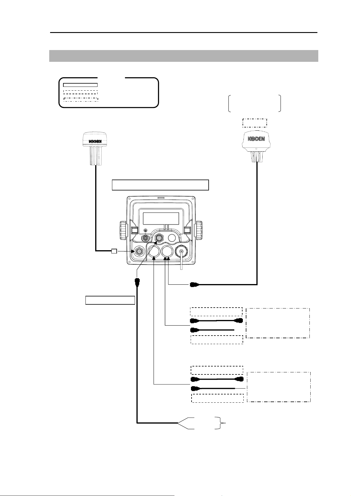
KGP-915 System Configuration
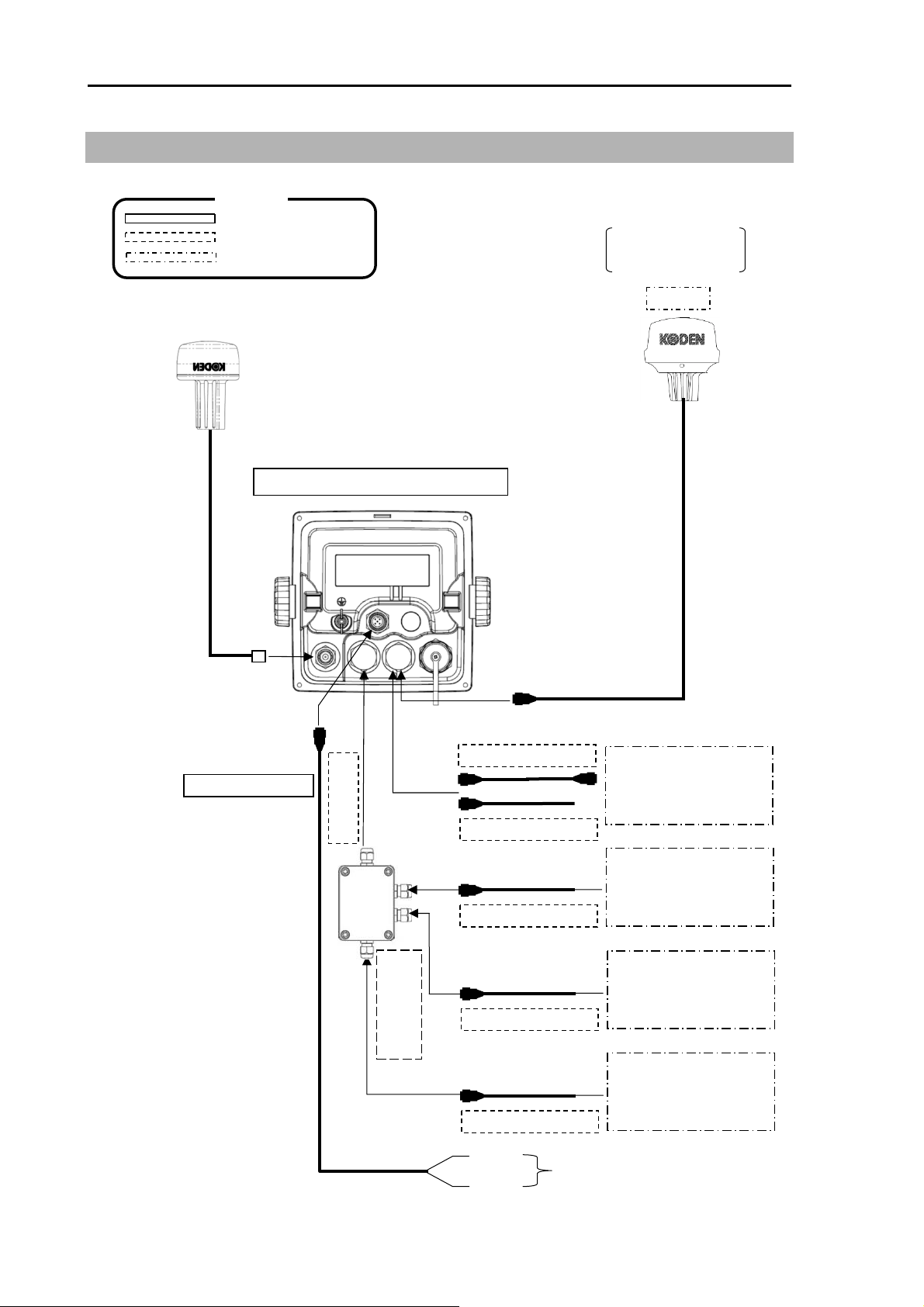
System Configuration
Connection diagram
GPS antenna GA-09
Legend
Standard configuration
Option
Owner supply
Software virsion:
KM-E34G and after
is required.
KBG-3
Display unit KGP-915
With mounting bracket and cover
POWER Connector
DATA 2 Connector
CW-276-2M
DATA 2 Connector
CW-373-5M
CW-376-5M
Marine radar
Chart Plotter
Echo sounder
Auto pilot
DATA 1 Connector
CW-373-5M
CW-376-5M
Marine radar
Chart Plotter
Echo sounder
Auto pilot
Red +
10.8 to 31.2VDC
Black -
0093129152-00 xi
Page 14
System Configuration KGP-915
System Configuration (with Junction box)
Connection diagram
GPS antenna GA-09
Legend
Standard configuration
Option
Owner supply
Software virsion:
KM-E34G and after
is required.
KBG-3
Display unit KGP-915
With mounting bracket and cover
POWER Connector
DATA 2 Connector
CW-276-2M
CW-376-5M
DATA 3 Connector
DATA 2 Connector
CW-373-5M
CW-376-5M
CW-376-5M
Marine radar
Chart Plotter
Echo sounder
Auto pilot
Marine radar
Chart Plotter
Echo sounder
Auto pilot
Junction Box
DATA 4 Connector
CW-376-5M
DATA 1 Connector
CW-376-5M
Red +
10.8 to 31.2VDC
Black -
Marine radar
Chart Plotter
Echo sounder
Auto pilot
Marine radar
Chart Plotter
Echo sounder
Auto pilot
xii 0093129152-00
Page 15
KGP-915 Configuration of Equipment
Configuration of Equipment
Standard Equipment Configuration List
No
Display unit
01
02
Antenna unit
04
05 DC power cable CW-276-2M
Truss tapping screw
06
07 Operation manual
Item Type name Remarks
KGP-915.MU
GA-09[10M]
With mounting bracket and front cover
Connected to GA-09, other end BNC
connector
GA-09[15M]
GA-09[0.5M]
TPT5X20U
KGP-915.OM.E
Connected to GA-09, other end N-P
connector
With 5-pin connector, other end
plain
For mounting bracket
English 1
Option List
No
01 Antenna holder RAH-29
02
Connecting cable
03 CW-376-5M
04 Junction box JB-35
05 Hose band 738-1015
06 Power rectifier PS-010
07 AC power cable VV-2D8-3M
08 Connector
Antenna cable extension kit
09
Antenna cable extension kit
10*
Conversion cable
11
Operation manual
12
Service manual
13
*10. N-BNC connector in the kit will not be used.
Item Type name Remarks
Ratchet mount
CW-373-5M
BD-06BFFA-LL6001
CW-839-30M KIT
CW-394-60M KIT
CW-826-0.5M
KGP-915.OM.E
KGP-915.SM.E
6 pin water resistant connectors both
ends
6 pin water resistant connector and
other end plain
1 input, 3 outputs with CW-376-5M
2pcs for antenna fixture
With 5A fuses 2pcs
For PS-010, both ends plain
6 pin water resistant connector for TD, CVS
5DFB cable with N-J connector and
other end plain, N-J connector, and
CW-826-0.5M
8DSFA cable with N-J connector and
other end plain, N-J connector, N-BNC
connector* and CW-826-0.5M
A BNC connector / N-P connector
English
English
Weight/Length
0.74 kg
0.68kg
10m
0.89kg
15m
0.29kg
0.5m
2.0m
Weight/
Length
0.68kg
3.5kg
0.5m
Q’ty
1
1 03
1
4
5m
5m
--
--
3 m
--
30m
60m
0093129152-00 xiii
Page 16

- This page intentionally left blank.-
Page 17
KGP-915 Chapter 1 Basic Operation
,
Chapter 1 Basic Operation
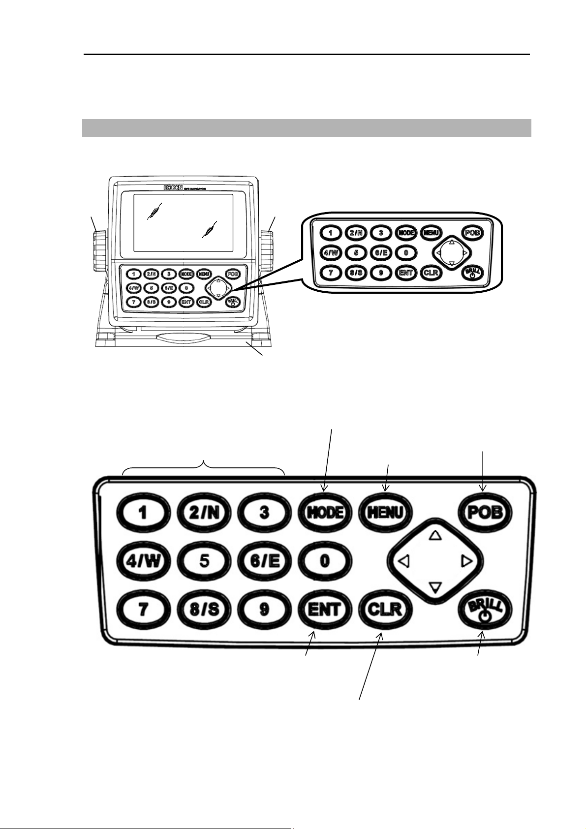
1.1 The name and function of each part
GNSS Receiver display
Knob
1.1.1 Control panel
Recalls memory position,
entry of numerical values,
and selection
North or South latitude or
East or West longitude
Knob
Mounting bracket
Selects NAV1, NAV2, NAV3,
NAV4
.
Control panel
NAV5 or NAV6 screen.
Activates POB (People
Over Board) function.
Recalls the menu
Enters a numeric/optional
parameter.
Clears numeric/optional
parameter or stops alarm
sound temporarily.
Turns the power on
Press and hold the power OFF
Changes the brightness
0093129152-00 1-1
Page 18
Chapter 1 Basic Operation KGP-915
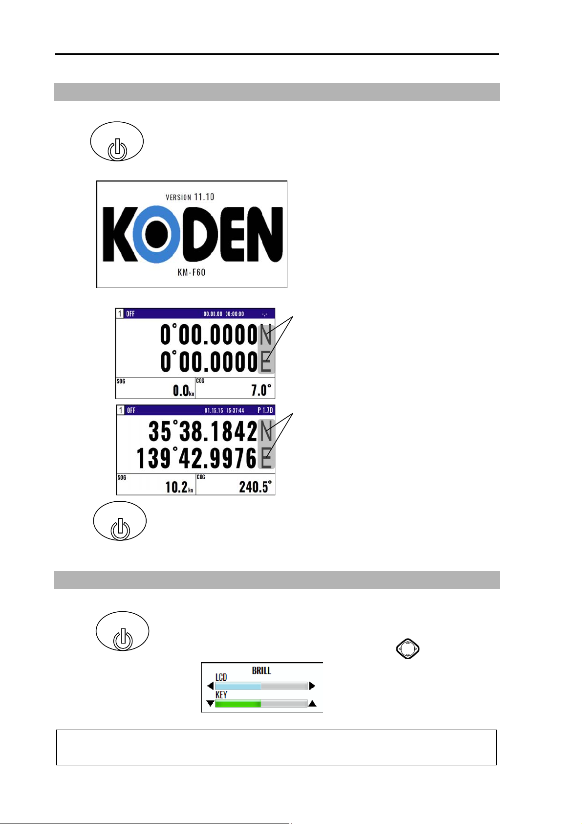
1.2 Power On/Off
BRILL
Press to power on.
Initial message appears during power-on.
The receiver is performing the self-check.
Blinking
Blink when NAVIGATOR is searching GPS
satellites.
No blinking
When NAVIGATOR receives signals from 3
or more satellites, it displays present latitude
and longitude position with solid N (or S) and
W (or E).
BRILL
Press until [Power off 3sec] is displayed for turn NAVIGATOR off.
All data before power-off is kept in memory for later use.
1.3 Adjusting brightness of display and panel key
NOTE: This setup is memorized and turns into the same setup next time at the time of a power
BRILL
Press to change the LCD brightness in 7 levels.
After the popup of below was displayed, push the key.
supply ON.
1-2 0093129152-00
Page 19
KGP-915 Chapter 1 Basic Operation
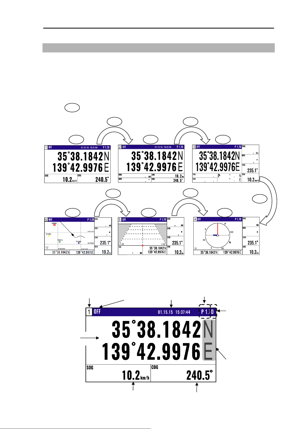
1.4 Selecting the screen
1.4.1 Display Modes
KGP-915 has 6 display modes: Nav data display1 (NAV1), Nav data display2 (NAV2), Nav data
display3 (NAV3), Navigation Graph display (NAV4), Highway display (NAV5), Plotter display (NAV6)
Screen will change in two ways.
1. Press numeric key on the upper-left corner of the screen
2. Press key to select the display mode.
MODE
MODE MODE
1 2/N 3
Nav data display1 Nav data display2
MODE
4/W 5 6/E
MODE
Nav data display3
MODE
Navigation Graph displayHighway displayPlotter display
1.4.2 Nav data display1 (NAV1) screen : Nav data1 mode
Screen
Setting destination
Time/Date
Position in latitude
and longitude
Speed
0093129152-00 1-3
P1.7 is DOP value
D is DGPS mode
Blinks when your position
has failed to fix
Course
Page 20
Chapter 1 Basic Operation KGP-915
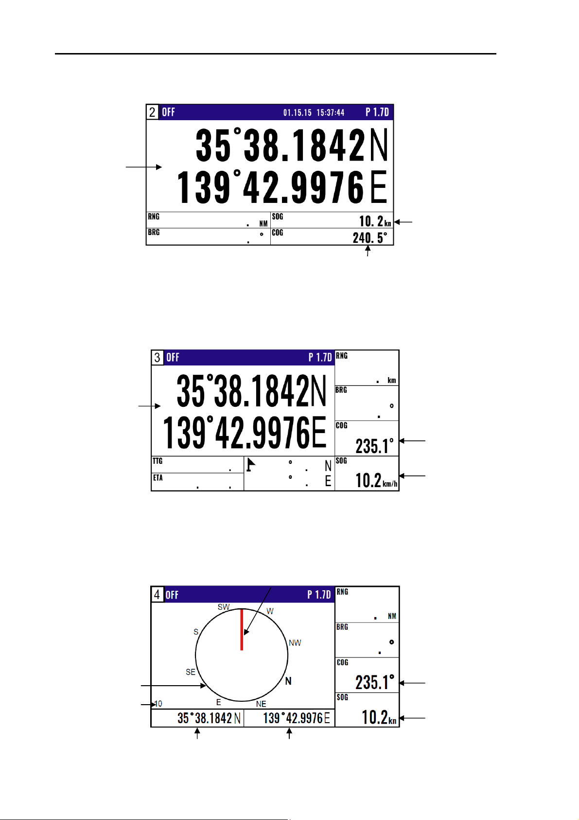
1.4.3 Nav data display2 (NAV2) screen : Nav data2 mode
Position in latitude
and longitude
Course
1.4.4 Nav data display3(NAV3) screen : Nav data3 mode
Position in latitude
and longitude
Speed
Course
Speed
1.4.5 Navigation Graph display (NAV4) screen : Navigation Graph mode
1-4 0093129152-00
Range ring
Range
Position in latitude Position in longitude
Heading Line
Course Over Ground
Speed Over Ground
Page 21
KGP-915 Chapter 1 Basic Operation
1.4.6 Highway display (NAV5) screen : Highway mode
XTE alarm range
Position in latitude
and longitude
1.4.7 Plotter display (NAV6) screen : Plotter mode
Own boat mark Heading Line
Course Over Ground
Speed Over Ground
Range
Course Over Ground
Speed Over Ground
Position in latitude
Position in longitude
0093129152-00 1-5
Page 22
Chapter 1 Basic Operation KGP-915
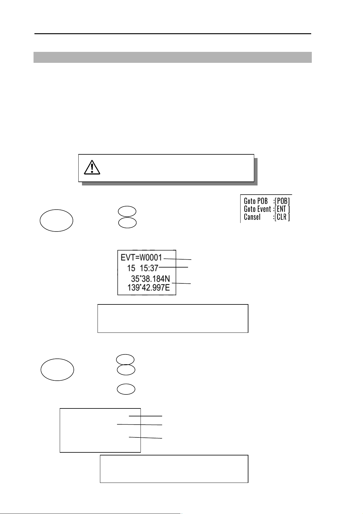
1.5 Storing present position (EVENT)
You can store up to 999 present positions with numbers 0001 to 0999. When you store additional
positions, the oldest position is deleted and the newest position is stored in its place.
• The storage date, hours and minutes, position data, and symbols (selectable on the PLOT screen)
can be stored.
• It is convenient to store the present position for use later in route navigation.
• These positions can be used as targets or waypoints.
• Event numbering is available both in the automatic or manual mode. Auto or Manual selection
is made at the “6.2.4 Changing a storing method for present position (Event)” (Refer Page 6-5)
EVT key does not function when positioning is
invalid
CAUTION
1.5.1 AUTO
POB
EVT
(1) Press key to appear the pop-up.
(2) Press key to store your present position.
(3) You can store up to 999 present positions by pressing this key. They
have storage numbers 0001 to 0999.
NOTE: Auto or Manual selection is made at the
POB
ENT
Increment Waypoint
Storage date (Day, Hour, Minute)
Storage position (Lat, Long)
“6.2.4 Changing a storing method for
present position (Event)”
1.5.2 MANUAL
POB
EVT
(1) Press key to show the registration number display window.
(2) Press key to store your present position.
(3) Specify a desired registration number by numeric keys.
Blinks for 10 seconds
EVT=W0001->0000
+ 15 04 : 59
1-6 0093129152-00
(4) Press key. The event will be registered to the number specified.
35°38 . 180N
139°42 . 990E
POB
ENT
ENT
The latest event number
Storage date (Day, Hour, Minute)
Storage position (Lat, Long)
NOTE: Auto or Manual selection is made at the
“6.2.4 Changing a storing method for
present position (Event)”
Page 23
KGP-915 Chapter 1 Basic Operation
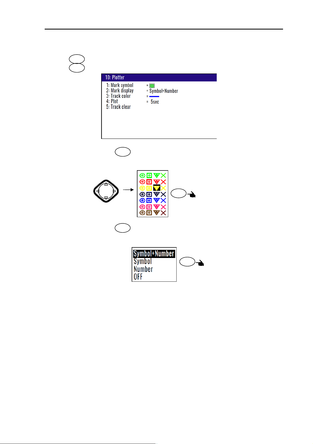
1.5.3 Changing the setup contents
(1) Press key until Menu options 1 to 10 appears.
(2) Press key to select “10: Plotter”.
(3) Various settings
1) 1: Mark symbol ( Press key )
MENU
0
1
To change the Mark symbol, place cursor on SYMBOL option and press ENT key.
Select symbol
Press
ENT
Key board cursor
Initial setup:
2) 2: Mark display ( Press key )
2/N
You can select whether or not to display the POB mark information.
Press
ENT
Initial setup: Symbol + Number
0093129152-00 1-7
Page 24
Chapter 1 Basic Operation KGP-915
y
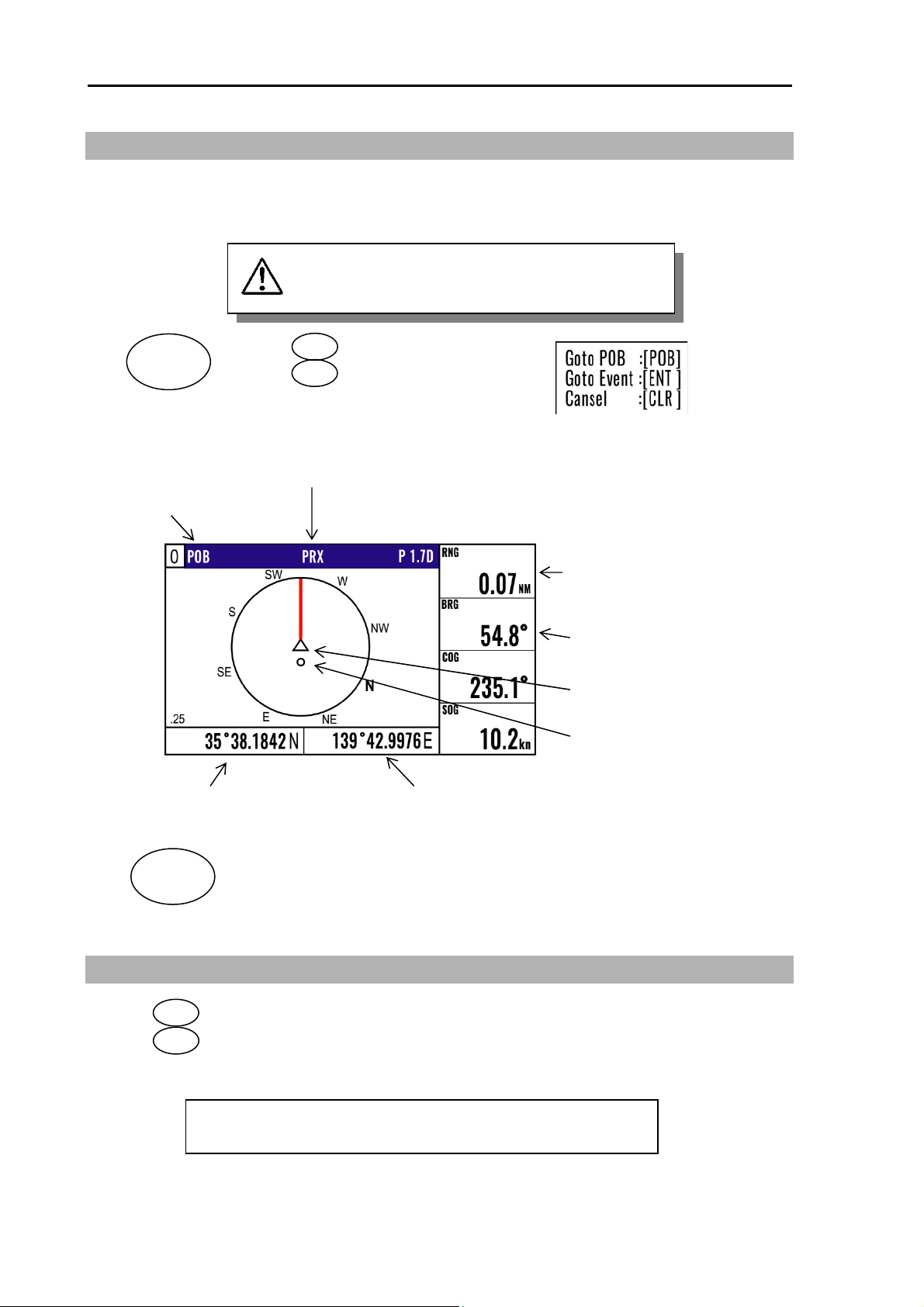
1.6 Using POB (People over-board)
POB function is provided for an emergency situation (if a person falls into the water) to make it easier to
return to POB point.
POB key does not function when positioning is
invalid
POB
EVT
(1) Press key to appear the pop-up.
(2) Press key to store POB position.
POB
POB
CAUTION
POB appears
Proximity alarm (blinking)
Alarm sounds when you approached 0.1 nm from
the point you pressed POB key.
Latitude of POB position Longitude of POB position
CLR
Clears the POB mode, and returns to the previous screen when you pressed
POB key. When alarm sounds, press CLR key to stop it. Press it again to
return to the screen you were at before you pressed POB key.
Distance (in nm) from your present
position to the point you pressed POB
key
Bearing to the point where you pressed
POB key
Present position
Point where you pressed
POB ke
1.7 Recalling Event and POB position
(1) Press key until menu options 1 to 10 appears.
(2) Press key to select “1:WAYPOINT”.
(3) Enter a storage number P0000 and W0001 to W0999 is POB and Event position data.
1-8 0093129152-00
MENU
1
NOTE: 000: Position data where you pressed POB key
0001 to 0999: Position data that contains events
Page 25
KGP-915 Chapter 1 Basic Operation
P0000 is POB position data
W0001~W0999 is
Event position data
W0999
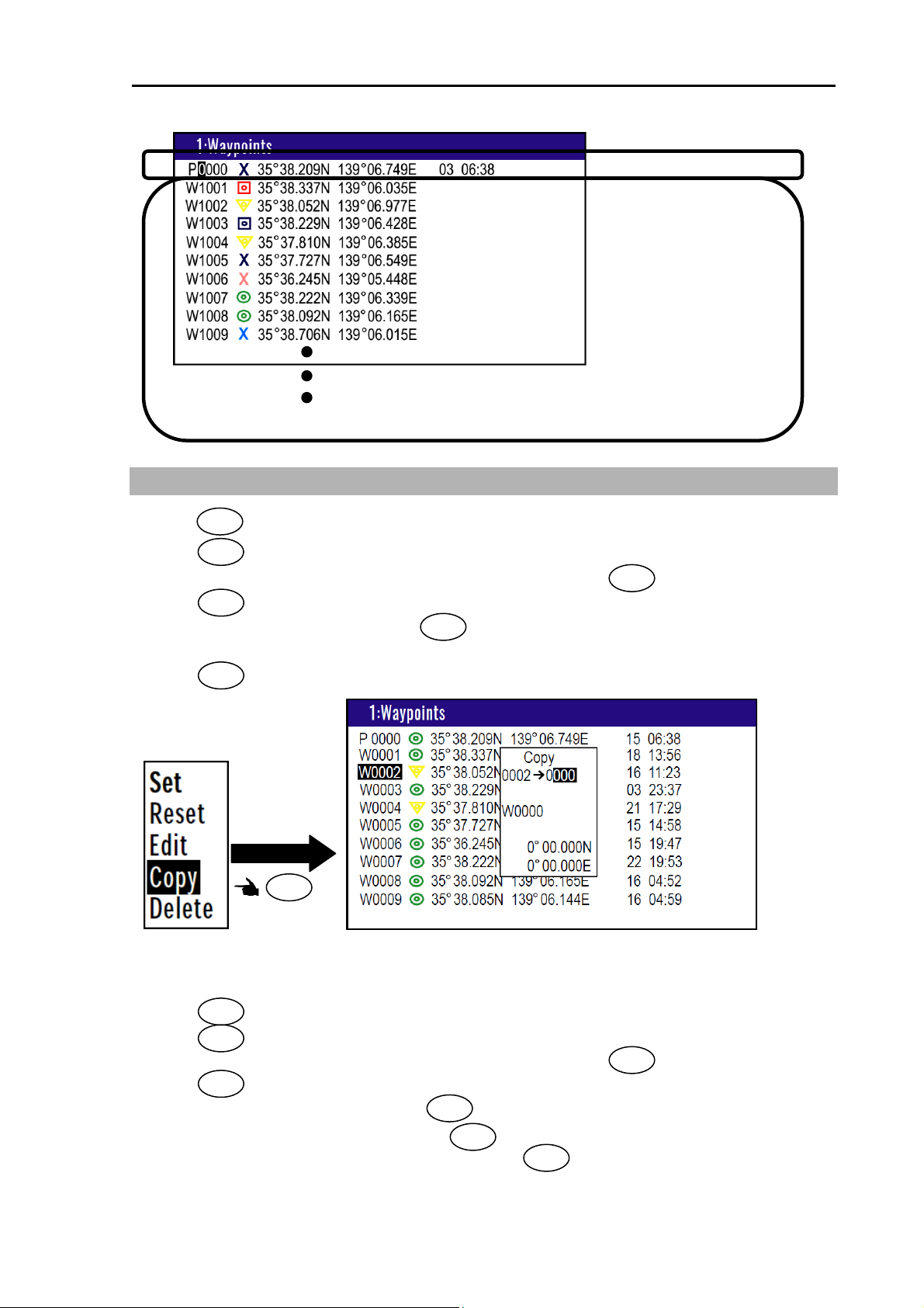
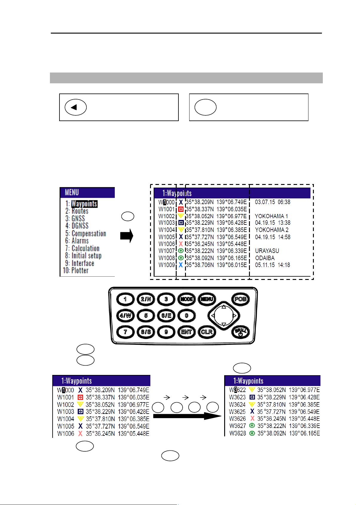
1.8 Copying Event and POB position
(1) Press key until Menu options 1 to 10 appears.
(2) Press key to select “1: Waypoints”
(3) Enter storage number (0000 to 0999) by numeric keys and press key.
(4) Press key to display the pop-up.
(5) Select [Copy] in the pop-up and press key.
MENU
1
ENT
ENT
ENT
(6) Enter a source point number (0000 to 0999) by numeric keys.
(7) Press key to copy the storage data.
ENT
Press
ENT
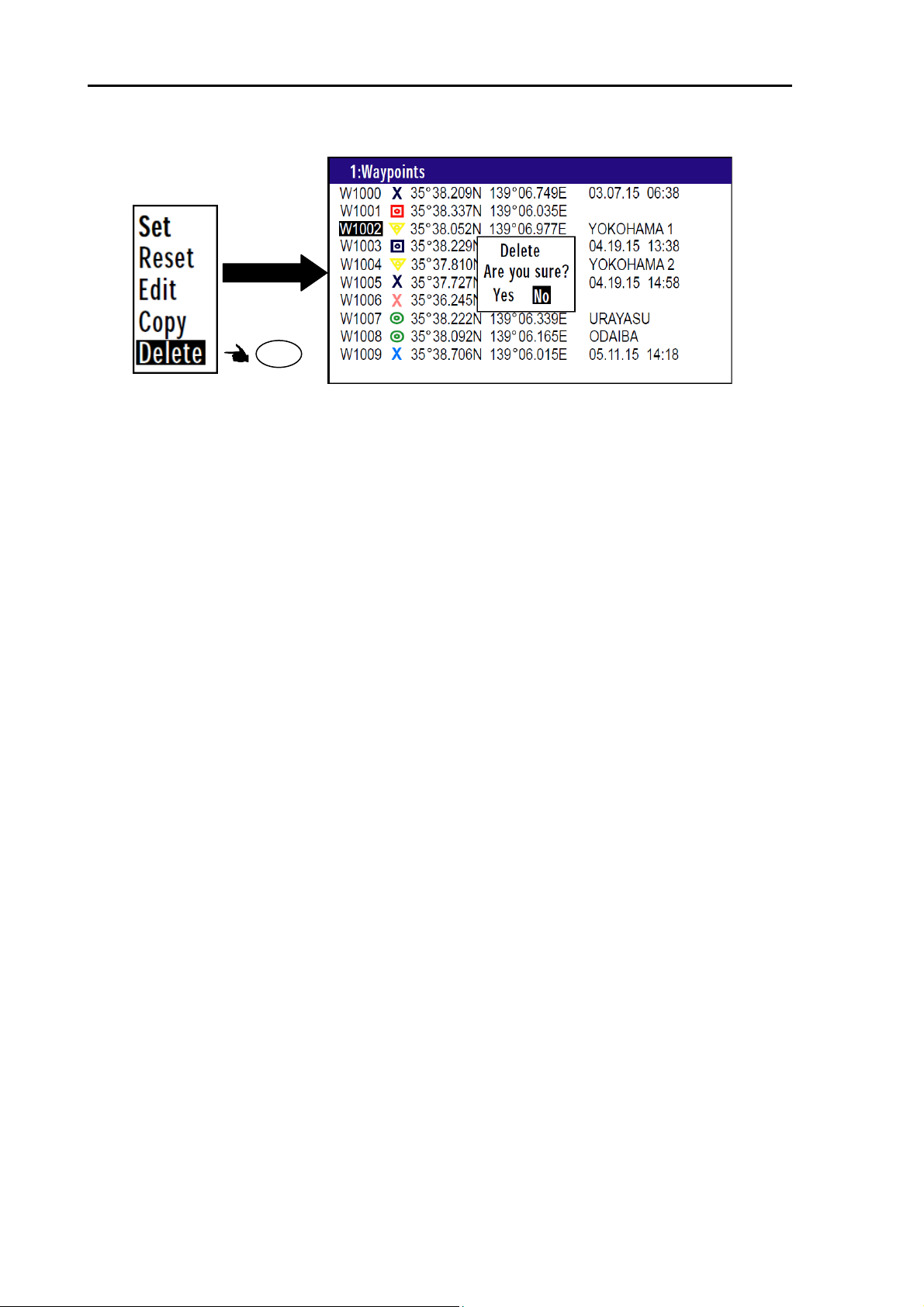
1.8.1 Erasing Event and POB position
(1) Press key until Menu options 1 to 10 appears.
(2) Press key to select “1: Waypoints”.
(3) Enter storage number (0001 to 0999) by numeric keys and press key.
(4) Press key to display the pop-up.
(5) Select [Delete] in the pop-up and press key.
(6) If OK, select [Yes] in the pop-up and press key.
0093129152-00 1-9
MENU
1
ENT
ENT
ENT
If cancel erasing, select [No] in the pop-up and press key.
ENT
ENT
Page 26
Chapter 1 Basic Operation KGP-915
Press
ENT
1-10 0093129152-00
Page 27
KGP-915 Chapter 2 Various Navigation
Chapter 2 Various Navigation
2.1 Storing waypoints (LAT/LONG) data
NOTE: Press to backspace the
cursor to correct an input
error.
2.1.1 Storing a new waypoint or updating an existing a waypoint
Up to 10000 waypoints can be stored in memory. As 1000 points (numbers 0000 and 0999) are
reserved for MOB and event registration, you can use 1000 to 9999 (total of 9000 points) to store
waypoints.
LAT/LONG mode (Example)
(1) Press key until Menu options 1 to 10 appears.
(2) Press key to select “1: Waypoints”.
MENU
1
(3) Enter storage number (0000 to 9999) by numeric keys and press key.
(4) Press key to display the pop-up.
ENT
(5) Select [Edit] in the pop-up and press key.
Press
1
key
3
6
ENT
NOTE: Press to clear incorrect
CLR
Input. You can reenter
Numeric data.
Storage position
Latitude Longitude Number
ENT
Press
2 2
Comment Mark
0093129152-00 2-1
Page 28
Chapter 2 Various Navigation KGP-915
(6) Move the cursor to where you want to change. [Mark] or [Latitude] or [Longitude] or [Comment]
Press [ ] [ ] key to move the cursor.
(7) If you want to change the [Mark].
1) Press key to select of the [Mark].
2) Press [ ] key to select the shape of the mark.
3) Press key.
(8) If you want to change the [Latitude] and [Longitude].
Example: The position “N35°38.180 / E139°42.990” is entered by pressing the following keys in
exact order given below. [3],[5],[3],[8],[1],[8],[0],[N],[1],[3],[9],[4],[2],[9],[9],[0],[E].
(9) If you want to change the [Comment].
1) Press key to select of the [Comment].
2) Press [ ] key to select a comment letter in the pop-up.
3) Finally press key after moved a cursor to the [DECISION] in the pop-up.
(10) Press [ ] [ ] key when the work has been completed.
Press
ENT
Pop-up appear
Press
ENT
ENT
ENT
ENT
ENT
2-2 0093129152-00
Page 29
KGP-915 Chapter 2 Various Navigation
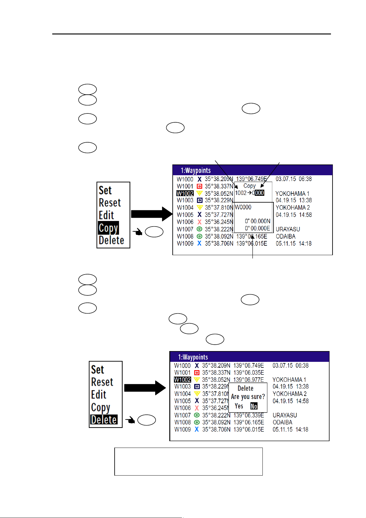
2.1.2 Copying a position
You can copy the position data (stored with numbers 0000 to 9999) to the waypoint data (having
numbers 1000 to 9999).
(1) Press key until Menu options 1 to 10 appears.
(2) Press key to select “1: Waypoints”.
(3) Enter storage number (0000 to 9999) by numeric keys and press key.
(4) Press key to display the pop-up.
(5) Select [Copy] in the pop-up and press key.
(6) Enter a source point number (1000 to 9999) by numeric keys.
(7) Press key to copy the storage data.
MENU
1
ENT
ENT
ENT
Original number
ENT
Enter the number of the copy destination
Press
ENT
Information of the copy destination
2.1.3 Erasing a single waypoint
(1) Press key until Menu options 1 to 10 appears.
(2) Press key to select “1: Waypoints”.
(3) Enter storage number (0001 to 9999) by numeric keys and press key.
(4) Press key to display the pop-up.
(5) Select [Delete] in the pop-up and press key.
(6) If OK, select [Yes] in the pop-up and press key.
MENU
1
ENT
ENT
ENT
If cancel erasing, select [No] in the pop-up and press key.
ENT
ENT
Press
ENT
NOTE: To erase an entire data from memory
simultaneously, see “WPT./Route clear”
(page 6-5).
0093129152-00 2-3
Page 30
Chapter 2 Various Navigation KGP-915
2.2 Setup of waypoint navigation
NOTE: Press to backspace the
cursor to correct an input
error.
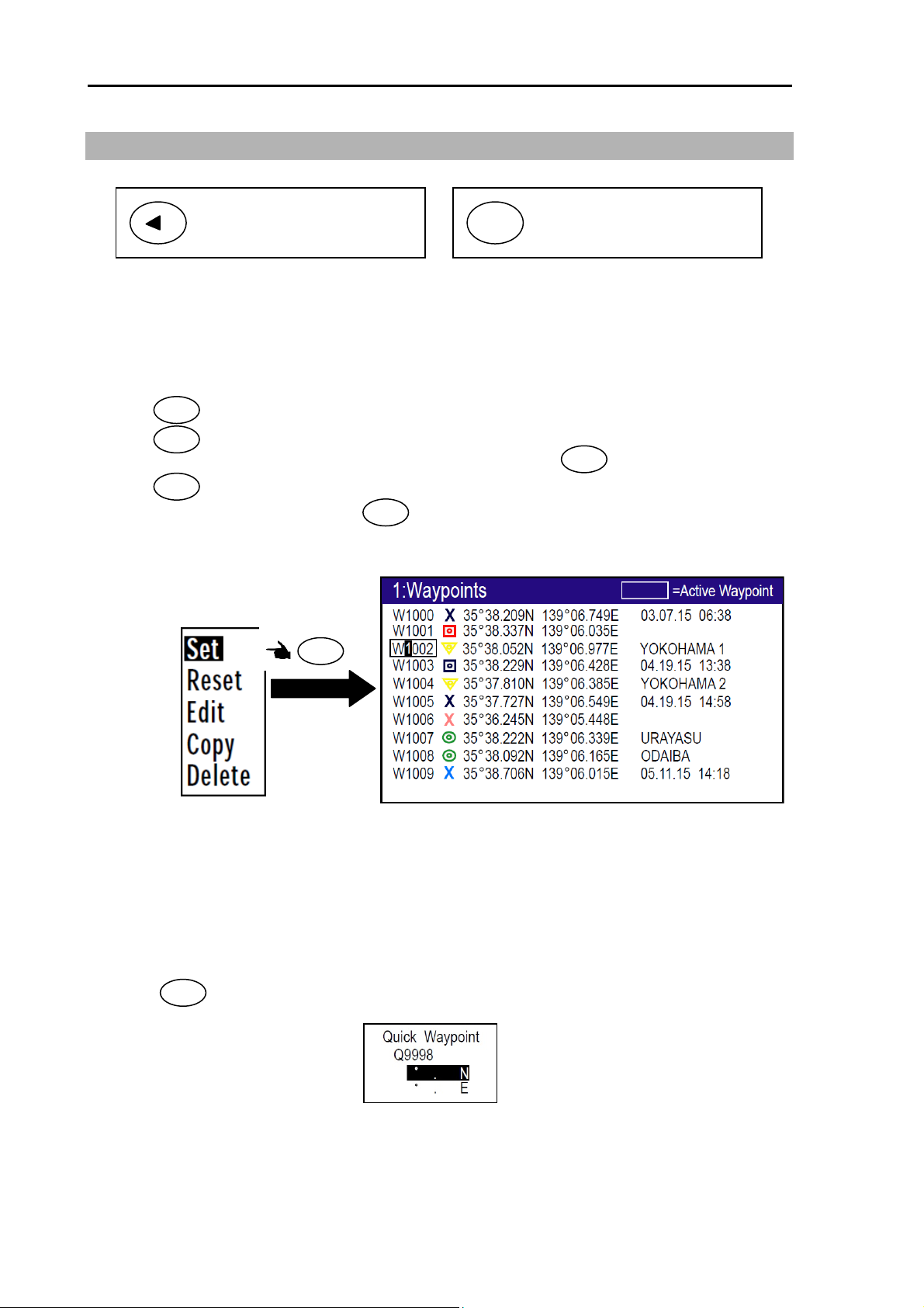
2.2.1 Setting waypoint navigation
The position data for each waypoint must be set prior to navigating to waypoints. You can use the data
already stored from Menu, or you can set the waypoints on A (NAV1), B (NAV2), C (NAV3) or D
(PLOT) screen (called the quick waypoint navigation).
(1) Press key until Menu options 1 to 10 appears.
(2) Press key to select “1: Waypoints”.
(3) Enter storage number (0000 to 9999) by numeric keys and press key.
(4) Press key to display the pop-up.
(5) Select [Set] in the pop-up and press key.
(6) Number is surrounded by square.
MENU
1
ENT
ENT
NOTE: Press to clear incorrect
CLR
Input. You can reenter
Numeric data.
ENT
Press
ENT
2.2.2 Quick waypoint setup
Quick WPT (first priority waypoint) can be set by specifying it directly either from the NAV1, NAV2,
NAV3, NAV4, NAV5 or NAV6 screen. When the new waypoint is selected, the waypoint navigation to it
will commence and the specified position, along with the comment (QUICK), will be assigned to the
position number 9998. Old data is replaced with a new during quick WPT setup.
While the 1st to 6th pages of either the NAV1, NAV2, NAV3, NAV4, NAV5 or NAV6, are displayed.
(1) Press key to display “QUICK” pop-up menu.
0
2-4 0093129152-00
Page 31

KGP-915 Chapter 2 Various Navigation
(2) Enter latitude and longitude.
For example, if “N35°38.180 / E139°42.990” is inputted, a key will be pressed in order of
[3],[5],[3],[8],[1],[8],[0],[N], [1],[3],[9],[4],[2],[9],[9],[0],[E].
(3) The waypoint is set and the point data is stored in number 9998.
2.2.3 Canceling waypoint navigation
To cancel waypoint navigation, turn WPT to Reset on NAV1, NAV2, NAV3, NAV4, NAV5 or NAV6
screen. There are two ways.
Cancel from [MENU].
Cancel from NAV1, NAV2, NAV3, NAV4, NAV5 or NAV6 screen.
1) When Reset from [MENU].
(1) Press key until Menu options 1 to 10 appears.
(2) Press key to select “1: Waypoints”.
(3) Enter storage number (0000 to 9999) by numeric keys and press key.
(4) Press key to display the pop-up.
(5) Select [Reset] in the pop-up and press key.
(6) No square from Number.
MENU
1
ENT
ENT
ENT
Press
ENT
2) When Reset from NAV 1, NAV 2, NAV 3, NAV4, NAV5 or NAV6 screen.
(1) Press key.
(2) If OK, select [Yes] in the pop-up and press key.
If cancel erasing, select [No] in the pop-up and press key.
CLR
ENT
ENT
0093129152-00 2-5
Page 32

Chapter 2 Various Navigation KGP-915
A
2.2.4 NAV2 screen during waypoint navigation
Position in latitude
and longitude
Distance from present
position from WPT
Waypoint number
larm
Bearing from present
position from WPT
ANCH: Anchor watch alarm
PROX: Proximity alarm
XTE: Cross track error alarm
CDI: Course deviation angle alarm
Time
Speed
Course
2.2.5 NAV3 screen during waypoint navigation
Position in latitude
and longitude
Time-To-Go
to destination
Estimated-Time-of-Arrival
at destination
Latitude and Longitude
of WPT
Distance from present
position from WPT
Bearing from present
position from WPT
Course
Speed
2-6 0093129152-00
Page 33

KGP-915 Chapter 2 Various Navigation
g
2.2.6 NAV4 screen during waypoint navigation
Heading Line
Own boat mark
Waypoint
Range rin
Range
Position in latitude Position in longitude
2.2.7 NAV5 screen during waypoint navigation
XTE alarm range
Distance from present
position from WPT
Bearing from present
position from WPT
Course Over Ground
Speed Over Ground
Distance from present
position from WPT
Own boat mark
Bearing from present
position from WPT
Course Over Ground
Speed Over Ground
Digital XTE indication
Position in latitude
and longitude
0093129152-00 2-7
Page 34

Chapter 2 Various Navigation KGP-915
2.2.8 NAV6 screen during waypoint navigation
Own boat mark Heading Line
Route
Waypoint
Distance from present
position from WPT
Bearing from present
position from WPT
Range
Course Over Ground
Speed Over Ground
Position in latitude Position in longitude
2-8 0093129152-00
Page 35

KGP-915 Chapter 2 Various Navigation
f
2.3 Cross track error and course deviation angle
2.3.1 Navigation graph of NAV4 screen
Use the navigation graph to check the distance and bearing to the waypoint. When the distance to WPT
is further than the range (radius) of navigation graph, the WPT locates on the circle of navigation graph.
When the distance is closer than the graph range, the WPT marking is shown in the circle. The XTE bar
graph and course deviation angle bar graphs appear only when the WPT is on the circle (these graphs
are cleared in the short distance).
Waypoint
Distance from present
Position to WPT
Bearing to WPT
True north
Steer to the left to get back
to the original course.
Course deviation angle
Course
Steer to the right to get back
to the original course.
Steering direction
NOTE: Changing the range(radius) o
Navigation graph
1. Press [MODE] key until NAV4 screen
appears.
2. Press to [ ] or [ ] key to select a
desired range.
The range that can be changed is as follows.
(0.25, 0.5, 1, 2, 5, 10, 20, 50, 100, 200)
NOTES:
1. The cross track error (XTE) indication is 9.99
(nm, sm,km) maximum, and doesn't change
beyond that limit.
2. The XTE bar graph responds up to 1.00 (nm,
sm, km) deviation, and doesn't change
beyond that limit.
3. To set an XTE alarm, see the "Setting and
canceling" (page 3-3/4).
4. The course deviation angle indication is 180
degrees maximum.
0093129152-00 2-9
Origin
Page 36

Chapter 2 Various Navigation KGP-915
p
A
, B,
2.3.2 Highway display (NAV5) screen
Use the three-dimensional chart for navigation on the course line. You can set a course width from
Menu (6: Alarm). Symbol “ ” shows the waypoint, and your ship and track are shown along the
course line.
(When waypoint is distance)
When the distance is greater than 4 (nm, sm, km), the 4(nm, sm, km) course line is shown on the
screen. When you have sailed 2 (nm, sm, km), the present position indication moves toward you and
the next 4 (nm, sm, km) are shown.
Waypoint
Distance on
course line
Distance to
WPT
At point E
You are sailing outside
of course width.
Present position
This marking moves at the
course edge.
Course line
Course line length on
the screen
Examples: The screen changes as follows when you sail along
oints
C and D.
At point D At point C
Present position Present position
At point B At point A
Present position
Present position
XTE alarm range
You can change the XTE alarm range by “Setting and canceling” (page 3-3/4).
2-10 0093129152-00
Page 37

KGP-915 Chapter 2 Various Navigation
(Nearing to the WPT)
When you are close to the waypoint, the course line length decreases to 4 (nm, sm, km), 2 (nm, sm,
km) and 1 (nm, sm, km). Then, the WPT marking closes to your ship.
Waypoint
NOTES: WPT marking changes:
When distance on course line is greater than 4 (nm, sm, km)
When distance on course line is less than 4 (nm, sm, km)
At point K: Distance to WPT is greater
At point
the waypoint.
than 1 (nm, sm, km).
J: You have reached
Present position
Waypoint
The WPT indication remains close
to you, but the course length
increases to 1 (nm, sm, km), 2 (nm,
sm, km), and 4 (nm, sm, km). The
WPT indication changes when the
length exceeds 4 (nm, sm, km).
Waypoint
The WPT marking moves
toward you.
Present position
At point I: You are 0.5 (nm, sm, km)
away from waypoint.
Waypoint
The WPT marking moves to
the center of course line.
Present position
H: You are 1 (nm, sm, km)
At point
away from waypoint.
Waypoint
The course length closing up to
1 (nm, sm, km) scale from
2 (nm, sm, km) scale.
Present position
F: You are 4 (nm, sm, km)
At point
away from waypoint.
Waypoint
The present position indication
moves toward you and the WPT
indication changes when you have
reached 4 (nm, sm, km) on the
course line away from the
waypoint.
Present position
0093129152-00 2-11
Page 38

Chapter 2 Various Navigation KGP-915
2.4 Storing and erasing routes
NOTE: Press to backspace the
cursor to correct an input
error.
2.4.1 Storing your route
• Up to 100 routes and 50 waypoints can be registered for one route.
NOTE: Press to clear incorrect
CLR
Input. You can reenter
Numeric data.
(1) Press key until Menu options 1 to 10 appears.
(2) Press key to select “2: Route”.
(3) Press key to select “1: Route Set / Edit”. Route Input screen is displayed.
(4) Enter a route number (01 to 100) by numeric keys and press key.
(5) Press key to display the pop-up.
(6) Select [Edit] in pop-up and press key.
ENT
2/N
1
ENT
ENT
ENT
Press
ENT
(6) Move the cursor to where you want to change. [Comment] or [Waypoint]
Press [ ] [ ] key to move the cursor.
Input of Comment
Input location of Waypoint
(7) If you want to change the [Comment]
1) Press key to select of the [Comment].
ENT
2) Press [ ] key to select a comment letter in pop-up.
3) Press key to after moved a cursor to the [DECISION] in the pop-up.
ENT
2-12 0093129152-00
Page 39

KGP-915 Chapter 2 Various Navigation
(8) If you want to change the [Waypoint]
1) Press key to select of the
ENT
Input location of Waypoint.
2) Enter a waypoint number (0000 to 9999) of the route by numeric keys. (You can check its
memory data on the screen.)
3) Press key to store the waypoint number.
ENT
(9) Repeat (8) steps to set another waypoint in the route.
2.4.2 Automatic switching of waypoints
Route navigation can switch the current waypoint in two ways: switching in CIRCLE mode and
switching in BI-SECTOR mode. In CIRCLE mode, the next waypoint is shown when you reach the
proximity alarm circle. In BI-SECTOR mode, the next waypoint is shown when you cross a half-angle
line.
CIRCLE mode
Proximity
Alarm circle
BI-SECTOR mode
Waypoint
Waypoint Course line B Course line A
Course line A Course line B
(1) Press key until Menu options 1 to 10 appears.
(2) Press key to select “2: Route”.
(3) Press key to select “2: CHANGE”.
When you reach the proximity alarm circle,
the course line is switched from A to B. To
change the proximity alarm range, see
“Setting and canceling” (page 3-3/4).
MENU
2/N
2/N
When you cross a half-angle line, the
course line is switched from A to B.
(4) Press [ ] or [ ] key to locate cursor to select a mode.
(5) Press key. The selected mode will be shown.
ENT
2.4.3 Copying a single route
(1) Press key until Menu options 1 to 10 appears.
(2) Press key to select “2: Route”.
(3) Press key to select “1: Route Set / Edit”. Route Input screen is displayed.
(4) Enter a route number (01 to 100) using numeric keys and press key.
(5) Press key to display the pop-up.
(6) Select [Copy] in the pop-up and press key.
(7) Enter a source point number (001 to 100) by numeric keys.
(8) Press key to copy the route data.
MENU
2/N
1
ENT
ENT
ENT
ENT
0093129152-00 2-13
Page 40

Chapter 2 Various Navigation KGP-915
Press
ENT
2.4.4 Erasing point data
(1) Press key until Menu options 1 to 10 appears.
(2) Press key to select “2: Route”.
(3) Press key to select “1: Route Set / Edit”. Route Input screen is displayed.
(4) Enter a route number (01 to 100) by numeric keys and press key.
(5) Press key to display the pop-up.
(6) Select [Edit] in the pop-up and press key.
(7) If you want to delete any Waypoint, press key in a place that is registered
(8) If OK, select [Yes] in the pop-up and press key.
If Cancel, select [No] in the pop-up and press key.
MENU
2/N
1
ENT
ENT
ENT
CLR
ENT
ENT
Clear
Press
CLR
2.4.5 Erasing a single route
(1) Press key until Menu options 1 to 10 appears.
(2) Press key to select “2: Route”.
(3) Press key to select “1: Route Set / Edit”. Route Input screen is displayed.
(4) Enter a route number (01 to 100) by numeric keys and press key.
MENU
2/N
1
ENT
2-14 0093129152-00
Page 41

KGP-915 Chapter 2 Various Navigation
(5) Press key to display the pop-up.
(6) Select [Delete] in the pop-up and press key.
(7) Press key to display the pop-up.
(8) If OK, select [Yes] in the pop-up and press key.
If Cancel, select [No] in the pop-up and press key.
ENT
ENT
ENT
ENT
ENT
Press
ENT
NOTE: To erase all stored data from memory, see “WPT./Route clear” (page 6-5).
2.5 Route setup
You can use up to 50 points to go to a final destination using route navigation. You can also reverse the
navigation route to return to the start point. To do so, you must first store the waypoints and route from
MENU 1. See “2.1 Storing waypoints (LAT/LONG) data” (page 2-1).
You can set the route by entering a route number, forward/backward navigation, and start waypoint
number of the route.
2.5.1 Selecting route navigation
You navigate on a route, following the course line, which is automatically updated as you reach each
waypoint. Use the following steps to start route navigation.
Select the reverse navigation only after you have reached the final destination, or the route navigation
may not work properly.
(1) Press key until Menu options 1 to 10 appears.
(2) Press key to select “2: Route”.
(3) Press key to select “1: Route Set / Edit”. Route Input screen is displayed.
(4) Enter a route number (01 to 100) by numeric keys and press key.
(5) Press key to display the pop-up.
MENU
2/N
1
ENT
ENT
Route
Direction
Press
ENT
First destination
0093129152-00 2-15
Page 42

Chapter 2 Various Navigation KGP-915
(6) Select [Set] in the pop-up and press key.
ENT
(7) You can select the first destination. In addition, you can be selected to Forward and Reverse.
1) Press [ ] key if you go Forward.
Press [ ] key if you go Reverse.
2) Select the first destination.
3) Determined by key.
ENT
(8) Number is surrounded by square.
2.5.2 Checking a route point position
You can check the waypoints on a route from the Menu.
(1) Press key until Menu options 1 to 10 appears.
(2) Press key to select “2: Route”.
(3) Press key to select “1: Route Set / Edit”. Route Input screen is displayed.
(4) Enter a route number (01 to 100) by numeric keys and press key.
(5) Press key to display the pop-up.
(6) Select [Edit] in the pop-up and press key.
MENU
2/N
1
ENT
ENT
ENT
2-16 0093129152-00
Page 43

KGP-915 Chapter 2 Various Navigation
2.5.3 Canceling route navigation
To cancel waypoint navigation, turn Route to OFF on A (NAV1), B (NAV2), C (NAV3) or D (PLOT)
screen.
Cancel from [MENU]
Cancel from NAV 1, NAV 2, NAV 3, NAV4, NAV5 or NAV6 screen.
1) When Reset from [MENU]
(1) Press key until Menu options 1 to 10 appears.
(2) Press key to select “2: Route”.
(3) Press key to select “1: Route Set / Edit”. Route Input screen is displayed.
(4) Enter a route number (01 to 100) by numeric keys and press key.
(5) Press key to display the pop-up.
(6) Select [Edit] in the pop-up and press key.
MENU
2/N
1
ENT
ENT
ENT
Press
ENT
2) When Reset from NAV1, NAV2, NAV3, NAV4, NAV5 or NAV6 screen.
(1) Press key.
(2) If OK, select [Yes] in the pop-up and press key.
If Cancel, select [No] in the pop-up and press key.
CLR
ENT
ENT
2.5.4 Switching between distance and time to go
When you select the “RNG” (Distance to WPT) or “TRNG” (Total distance) on NAV2, NAV3, NAV4,
NAV5 or NAV6 screen in route navigation, the respective “TTG” (Time to go to WPT) or “T.TTG” (Total
time to go) is shown.
(1) Press key until NAV2, NAV3, NAV4, NAV5 or NAV6 screen appears.
(2) Press [ ] key to display “RNG” “TTG”.
NOTE: “RNG” shows the distance to the next waypoint.
“TRNG” shows the total distance to the final
destination.
”
“
MODE
0093129152-00 2-17
Page 44

Chapter 2 Various Navigation KGP-915
(3) Press [ ] key to display “TRNG” “T.TTG”.
2-18 0093129152-00
Page 45

KGP-915 Chapter 2 Various Navigation
2.6 Setting an anchor position
After arriving at your destination, it is possible to drift from the anchor position due to a tide or wind.
Once the anchor position is stored in memory, it is easy to check the distance and bearing moved from
the anchor position.
2.6.1 Storing an anchor position
You can set the anchor position from the NAV2, NAV3, NAV4, NAV5 or NAV6 screen.
The following operations allow you to store and specify the current position as the anchor position. The
anchor position is registered to memory number A9997 along with the comment.
(1) Press key until Menu options 1 to 10 appears.
(2) Press key to select “6: Alarms”.
(3) Press key to select “2: ANCH”.
(6) Select [ON] in the pop-up and press key.
(5) Press key until NAV2, NAV3, NAV4, NAV5 or NAV6 screen appears.
(6) Press key.
(7) Press key. (Goto ANCH)
MENU
6/E
2/N
ENT
Press
6/E
MODE
POB
6/E
RNG: Distance from anchor position.
BRG: Bearing from anchor position.
Anchor setting mark
Anchor position
0093129152-00 2-19
Page 46

Chapter 2 Various Navigation KGP-915
Anchor mark
Anchor position
RNG: Distance from anchor position.
BRG: Bearing from anchor position.
2.6.2 Canceling anchor position
(1) Press key until NAV1, NAV2, NAV3, NAV4, NAV5 or NAV6 screen appears.
(2) Press key.
(3) If OK, select [Yes] in the pop-up and press key.
If Cancel, select [No] in the pop-up and press key.
MODE
CLR
ENT
ENT
2-20 0093129152-00
Page 47

KGP-915 Chapter 2 Various Navigation
2.7 Track display
You can display track, the waypoint, course line, and cross cursor on the NAV6 screen.
2.7.1 Display a cross cursor on NAV6 screen
You can display a cursor and position it on the screen.
(How to use cross cursor)
(1) Press key until NAV6 screen appears.
(2) When you press key, cursor appears.
MODE
ENT
(3) Press [ ] key to move display cursor.
Move quickly display cursor by pressing a long time [ ] key
Press
ENT
cursor appear
Press Long time
Press
Key board cursor
Display cursor is gradually faster
Display cursor
Move
Key board cursor
Display cursor
(How to store display cursor position)
(1) With the display cursor activated, press key to store the display cursor position. (Note: not
ENT
the present ship’s position).
Move the cursor to any point on the screen
Press
ENT
Appears EVT mark the position of the cursor
0093129152-00 2-21
Page 48

Chapter 2 Various Navigation KGP-915
2.7.2 Screen scrolling
You can scroll the NAV6 screen in any direction so that your ship is always shown on the screen. If
your ship moves off the screen, it will automatically return to the center of the display.
NAV6 screen moves by pressing [ ] key, when display cursor is not displayed.
Press key when you return to the current position.
5
2.7.3 Scaling the PLOT screen
You can select a display scale of PLOT (pages: 1, 2, 4) screen.
(1) Press to or key to select a desired range.
The range that can be changed is as follows.
(0.25, 0.5, 1, 2, 5, 10, 20)
2/N 8/S
2/N
Range Up
Scale indication fields
Range Down
8/S
Initial scale: 0.025
NOTE: You can change the scale unit from Menu 2: UNIT (nm) of 8: INITIAL
2.7.4 Changing the setup contents
(1) Press [MENU] key until Menu options 1 to 10 appears.
(2) Press [0] key to select “10: Plotter”.
2-22 0093129152-00
Page 49

KGP-915 Chapter 2 Various Navigation
(3) Various settings
1) 1: Mark symbol (Press key)
To change the Mark symbol, place cursor on SYMBOL option and press ENT key.
1
Select symbol
Press
ENT
Key board cursor
2) 2: Mark display (Press key)
2/N
You can select whether or not to display the Event mark information.
Press
ENT
3) 3: Track color (Press key)
3
Initial setup: Symbol + Number
You can select the color of the future Track.
Color select
Initial setup:
(Green)
Press
ENT
Initial setup:
(Green)
4) 4: Plot (Press key)
4W
To adjust the track recording interval (time or distance interval), locate cursor on PLOT option, and
press ENT key.
You can set the unit of track distance interval from the Menu 8-2: Units
Select color
Press
ENT
Initial setup: 5sec.
Plot speed select
0093129152-00 2-23
Page 50

Chapter 2 Various Navigation KGP-915
5) 5: Track clear (Press key)
5
You can delete the track according to color or all color.
If you press the ENT key when the cursor is positioned at Track clear, the pop-up of select color will
appear. Press ENT key after select color.
Select delete color
ENT
Press
Confirmation screen
All
Select Yes or No
Press
ENT
2-24 0093129152-00
Page 51

KGP-915 Chapter 3 Alarms
Chapter 3 Alarms
3.1 Kinds of alarms
There are five kinds of alarms, GNSS Fix, anchor watch (ANCH), proximity (PROX), cross track error
(XTE) and course deviation angle (CDI).
3.1.1 GNSS Fix
If you set ON of GNSS Fix alarm, alarm warns by short beep once when position is lost. And alarm
warns again after position fix.
3.1.2 Anchor watch alarm (ANCH)
An anchor watch alarm can alert you if your boat drifts a set distance from where it is activated. This
alarm function will not work if the alarm range is set to "0.00". ANCH letters blink and buzzer (short
beep) sounds when outside of alarm range. Please refer 2.6.1 Storing an anchor position.
Press CLR key If you want to turn off buzzer.
Anchor position
Preset anchor watch alarm range
Blink
0093129152-00 3-1
Initial setup: OFF, 1.00NM
Enter an alarm range: 0.00 to 9.99
Page 52

Chapter 3 Alarms KGP-915
3.1.3 Proximity alarm (PROX)
A proximity alarm alerts you when you arrive to within a preset distance to a waypoint.
The proximity alarm will not work if the alarm range is set to "0.00". Note: you will automatically
advance to the next waypoint at the alarm range if you have selected the CIRCLE mode of route
navigation by "Automatic switching of waypoints" (page 2-13). PRX letters blink and buzzer (short
beep) sounds when I arrive. Press CLR key, if you want to turn off buzzer.
Preset alarm range
Blink
Waypoint or route point
Initial setup: ON, 1.00
Enter an alarm range: 0.00 to 9.99
3.1.4 Cross track error alarm (XTE)
The cross track error (XTE) alarm alerts you when you have deviated from your course line by a
predetermined distance. The alarm function does not work if the alarm range is set to '0.00'. The course
width shown on NAV3 screen is the same as the XTE alarm value you have set. XTE letters blink and
buzzer (long beep) sounds when I’m away from XTE range.
Press CLR key, if you want to turn off buzzer.
Origin
Present alarm range
Waypoint or
route point
Course line
Blink
Cross track error (XTE)
Initial setup: ON, 1.00
Enter an alarm range: 0.00 to 9.99
3-2 0093129152-00
Page 53

KGP-915 Chapter 3 Alarms
3.1.5 Course deviation angle alarm (CDI)
The CDI alarm alerts you when you deviate from your course to steer by a predetermined margin.
The alarm function does not work if the alarm range is set to “00”. CDI letters blink and buzzer (long
beep) sounds when I’m away from CDI range. Press CLR key, if you want to turn off buzzer.
Bearing to waypoint
Course deviation angle (CDI)
Waypoint or route point
Course
Initial setup: ON, 45 degrees
Enter an alarm range: 00 to 99 degrees
3.2 Alarm explanation
The reason of an alarm can be seen in the following ways.
(1) Press key until Menu options 1 to 10 appears.
(2) Press key to select “6: Alarms”.
(3) Press key to select “6: Message”. Reason for alarm notification is displayed
MENU
6/E
6/E
Press
ENT
3.3 Setting and canceling
(Setting alarm)
(1) Press key until Menu options 1 to 10 appears.
(2) Press key to select “6: Alarms”.
(3) Select item number of the alarm to be set by numeric keys.
(4) Press [ ] or [ ] key to move cursor to ON.
(5) Press key.
0093129152-00 3-3
MENU
6/E
ENT
Page 54

Chapter 3 Alarms KGP-915
(Changing alarm range)
(1) Press key until Menu options 1 to 10 appears.
(2) Press key to select “6: Alarms”.
(3) Select item number of the alarm to be set by numeric keys.
(4) Press [ ] key to move cursor to alarm range field.
(5) Enter an alarm range by numeric keys. CDI alarm range is 2-digit.
(6) Press key.
MENU
6/E
ENT
(Canceling alarm)
(1) Press key until Menu options 1 to 10 appears.
(2) Press key to select “6: Alarms”.
(3) Select desired alarm number by numeric keys.
(4) Press [ ] or [ ] key to move cursor to [OFF].
(5) Press key.
MENU
6/E
ENT
3-4 0093129152-00
Page 55

KGP-915 Chapter 4 Setup Procedure
Chapter 4 Setup Procedure
4.1 Menu options
NOTE: You can select an option from Menu in two ways: by direct
numeric key entry or by cursor shifting. This manual explains
how to enter numeric values for easy understanding, but you
can also use the cursor for option selection.
(1) Waypoints
Store, edit, copy and erase waypoints. (See pages 2-1 to 2-5)
(2) Routes
Store and erase a route. Forward/backward navigation Selection. Automatic route switching. Waypoint
data switching. (See pages 2-12 to 2-18).
(3) GNSS
Display GNSS satellite status. Switch (2- and 3-dimensional) positioning modes. Select datum. Set
antenna height (above sea level). See DOP value to limit fix data Set satellite elevation angle limit.
Select RAIM function. Select RAIM accuracy.
0093129152-00 4-1
Page 56

Chapter 4 Setup Procedure KGP-915
(4) Differential GNSS (DGNSS)
Select DGNSS style. Select DGNSS mode. Set DGNSS timeout. Select beacon station. Set beacon
frequency. Select beacon bit rate. Set DGNSS input baud rate. Monitor DGNSS data. Monitor beacon
message.
(5) Compensation
Position correction (LAT/LONG, LOPs) Compass correction Time difference
(6) Alarm (See pages 3-1 to 3-4)
Anchor watch alarm. Proximity alarm. XTE alarm. CDI alarm. Alarm message.
(7) Calculation
Distance and bearing between two points LAT/LONG into LOPs data conversion Calculation of
estimated time length from the current position to the destination, or required speed.
4-2 0093129152-00
Page 57

KGP-915 Chapter 4 Setup Procedure
(8) Initial setup
Set average constants. Select distance/speed units. Select antenna height (above sea level) units.
Select navigation mode. Select position display mode (LAT/ LONG, LOPs). Select LAT/LONG display
digits Set chain.
(9) Interfacing
Select output format. Edit the output format (IEC 61162-1). Select ACK/ALARM output
(10) Plotter
You can change the settings of [Plotter]. NAV6 screen
0093129152-00 4-3
Page 58

Chapter 4 Setup Procedure KGP-915
4.2 Menu 3: GNSS
4.2.1 Monitoring GNSS satellite signal reception
You can monitor the signal status from GNSS (SBAS) satellites. The signals from 3 satellites are used
for two-dimensional positioning, but signals from 4 or more satellites are required for three-dimensional
positioning.
(1) Press key until Menu options 1 to 10 appears.
(2) Press key to select “3: GNSS”.
(3) Press key to select “1: GNSS Monitor”. Reason for alarm notification is displayed
MENU
3
1
Press
1
4.2.2 Selecting a GNSS mode
There are the three modes, GPS, GPS+GLONASS. Usually, it is used in GPS mode.
(1) Press key until Menu options 1 to 10 appears.
(2) Press key to select “3: GNSS”.
(3) Press key to select “2: GNSS mode”.
(4) Press [ ] or [ ] key to select desired measuring system mode.
(5) Press key.
MENU
3
2/N
ENT
Press
2/N
Initial setup: GPS
4-4 0093129152-00
Page 59

KGP-915 Chapter 4 Setup Procedure
4.2.3 Selecting a geodetic datum
The latitude and longitude are calculated based on the WGS-84 with GNSS system. However, the
charts used in many countries are based on different geodetic datum. You can compensate this
difference from your chart by converting GNSS position data into your actual chart system. To select a
geodetic datum, see "Local Geodetic Systems" (Chapter 9 Annex).
(1) Press key until Menu options 1 to 10 appears.
(2) Press key to select “3: GNSS”.
(3) Press key to select “3: DATUM”.
(4) Press [ ] or [ ] key to move cursor onto the desired geodetic datum.
(5) Press key.
MENU
3
3
ENT
Press
3
4.2.4 Setting the mask level of carrier-to-noise ratio
Usually this set value is used initial set other than the special case.
(1) Press key until Menu options 1 to 10 appears.
(2) Press key to select “3: GNSS”.
(3) Press key to select “4: C/N mask”.
(4) Press [ ] or [ ] key to move cursor onto the desired C/N mask.
(5) Press key.
MENU
3
4/W
ENT
Press
4/W
Initial setup: WGS-84
Initial setup: 10dB
0093129152-00 4-5
Page 60

Chapter 4 Setup Procedure KGP-915
4.2.5 Masking satellite elevation angle
When the satellite is below 5 degrees above the horizon, signal reflection and interference can cause
erroneous positioning. You can improve the positioning accuracy by masking the elevation angle.
However, a large mask value shortens the signal receive time and most satellite combinations are
rejected.
(1) Press key until Menu options 1 to 10 appears.
(2) Press key to select “3: GNSS”.
(3) Press key to select “5: Elevation mask”.
(4) Press [ ] or [ ] key to move cursor onto elevation angle masking.
(5) Press key.
MENU
3
5
ENT
Press
5
Initial setup: 5°
4-6 0093129152-00
Page 61

KGP-915 Chapter 4 Setup Procedure
4.3 Menu 4: Differential GNSS(DGNSS)
This DGNSS system can improve the GNSS positioning accuracy. There are three styles, Auto and
SBAS and Beacon. “BEACON” requires a signal from the external receiver system which outputs the
compensation data of RTCM SC-104. (Example KBG-3 or other brand)
“AUTO” mode is automatically changes SBAS and Beacon which continue DGNSS performance.
4.3.1 Displaying DGNSS
When the DGNSS is set, the DGNSS status is displayed with letters D by the top right corner of the
screen.
4.3.2 Selecting a style of DGNSS
Auto: DGNSS correction takes place when DGNSS correction data is received.
BEACON: DGNSS for RTCM SC-104.
SBAS: WAAS / EGNOS / MSAS / GAGAN / SDCM / Other
OFF: Normal GNSS positioning takes place. D letter is not shown.
(1) Press key until Menu options 1 to 10 appears.
(2) Press key to select “4: DGNSS”.
(3) Press key to select “1: DGNSS mode”.
(4) Press [ ] or [ ] key to move cursor onto “Auto” or “SBAS” or “BEACON” or “OFF”.
(5) Press key.
MENU
4
1
ENT
Press
1
Initial setup: Auto
0093129152-00 4-7
Page 62

Chapter 4 Setup Procedure KGP-915
4.3.3 Setting a DGNSS timeout
If the correction data from beacon receiver is interrupted or has errors, NAVIGATOR holds the last
differential correction for the duration of timeout. You can set Time out to 005 to 100 seconds. However,
the position accuracy degrades as Time out lengthens.
(1) Press key until Menu options 1 to 10 appears.
(2) Press key to select “4: DGNSS”.
(3) Press key to select “2: Time out”.
(4) Enter a timeout (005 to 100 seconds) by numeric keys.
(5) Press key.
MENU
4
2/N
ENT
Initial setup: 60 sec
4.3.4 Selecting a SBAS station
KGP-915 can utilize the SBAS. Kind of receivable SBAS is WAAS, EGNOS, MSAS, GAGAN, SDCM,
Other. There is an Auto function in the selection of SBAS. Auto function selects the nearest station.
PRN number zone becomes valid if you select the other. This mode is disable when “1: DGNSS mode”
is selected “BEACON” or “OFF”.
(1) Press key until Menu options 1 to 10 appears.
(2) Press key to select “4: DGNSS”.
(3) Press key to select “3: SBAS selection”.
MENU
4
3
(4) Press [ ] or [ ] key to move cursor onto selecting function.
(5) Press key.
ENT
Press
3
Initial setup: Auto
(Selecting a station in the Other mode)
(6) Press key to select “4: SBAS Other”.
4
(7) Enter a PRN number (120 to 158) by numeric keys.
(8) Press key.
ENT
4-8 0093129152-00
Page 63

KGP-915 Chapter 4 Setup Procedure
Press
4
Initial setup: PRN120
4.3.5 Selecting a beacon station (Beacon DGNSS only)
A beacon station is selectable in both the manual or auto mode. This mode is disable when “1: DGNSS
mode” is “SBAS” or “OFF”.
If the beacon receiver to be connected supports automatic tuning, in the auto mode, the nearest station
will be selected based on actual longitude and latitude among all the stored beacon stations.
(1) Press key until Menu options 1 to 10 appears.
(2) Press key to select “4: DGNSS”.
(3) Press key to select “5: Beacon selection”.
(4) Press [ ] or [ ] key to move cursor settings you select
(5) Press key.
MENU
4
5
ENT
Press
5
Initial setup: Auto
4.3.6 Setting receiving frequency and bit rate of a beacon station
You can set the receiving frequency (283.5 kHz to 325.0 kHz) that is transmitted from a beacon station.
In addition, Bit rate you can also change “50bps”, “100bps”, “200bps”. This mode is disabled when “5:
Beacon selection” is “AUTO”.
(1) Press key until Menu options 1 to 10 appears.
(2) Press key to select “4: DGNSS”.
(3) Press [ ] or [ ] key to move cursor “6: Frequency”.
(4) Specify receiving frequency (4-digit) of beacon station by numeric keys (0 to 9).
(5) Press key to set receiving frequency.
(6) Press [ ] key to move cursor onto “7: Bit rate”.
(7) Press key.
(8) Press [ ] or [ ] key to set bit rate “50bps”, “100bps”, “200bps”.
(9) Press key.
MENU
4
ENT
ENT
ENT
0093129152-00 4-9
Page 64

Chapter 4 Setup Procedure KGP-915
Frequency Initial setup: 283.5 kHz
Selectable range: 283.5 to 325.0 kHz
Bit rate Initial setup: 200 bps
4.3.7 Selecting the DGNSS input signal baud rate
Adjust the baud rate of RTCM SC-104 format signal reception to the output signal baud rate of beacon
receiver.
To change the baud rate, the following settings are required
(1) Press key until Menu options 1 to 10 appears.
(2) Press key to select “9: Interface”.
(3) “1: Connector”. = ‘’DATA2”
“2: Format”. = ‘’RTCM”
*Note:
To change the baud rate
This mode is disabled when “5: Beacon selection” is “AUTO”.
(1) Press key until Menu options 1 to 10 appears.
(2) Press key to select “4: DGNSS”.
(4) Press key to select “8: Baud rate”.
(5) Press [ ] or [ ] key to move cursor onto the correct baud rate “2400”, “4800”, “9600”,.
(6) Press key.
MENU
9
Without “9: Interface” setting, “4: DGNSS” in “8: Baud rate” cannot change
MENU
4
8
ENT
Press
8/S
4-10 0093129152-00
Page 65

KGP-915 Chapter 4 Setup Procedure
4.3.8 Beacon monitor
DGNSS monitor provides information on the DGNSS beacon receiver interface and receiving status.
(1) Press key until Menu options 1 to 10 appears.
(2) Press key to select “4: DGNSS”.
(3) Press key to select “9: Beacon monitor”.
MENU
4
9
Press
9
0093129152-00 4-11
Page 66

Chapter 4 Setup Procedure KGP-915
4.4 Menu 5: Compensation
4.4.1 Correcting your position
You can compensate your GNSS present position given by GNSS in the following two ways:
• Enter the latitude and longitude of your actual position by numeric keys.
• Enter the correction offset to use.
(Direct entry of actual position data)
When your present position is displayed in Latitude / Longitude mode, you can correct it by entering the
known Latitude/Longitude data.
(1) Press key until Menu options 1 to 10 appears.
(2) Press key to select “5: Compensation”.
(3) Press key to select “1: Latitude / Longitude”.
(4) Enter the correct latitude and longitude value.
Example: The position “N35°38.544 / E139°06.183” is entered by pressing the following keys in
exact order given below.
Correction offset
(Entry of correction offset)
When your present position is displayed in Latitude / Longitude mode, you can correct it by entering the
Latitude/Longitude correction data.
(1) Press key until Menu options 1 to 10 appears.
(2) Press key to select “5: Compensation”.
(3) Press key to select “1: Latitude / Longitude”.
(4) Press [ ] or [ ] key to move cursor onto correction offset field of latitude.
(5) Enter the latitude and longitude correction offset.
MENU
5
1
[3], [5], [3], [8], [5], [4], [4], [N], [ENT], [ ]
[1], [3], [9], [0], [6], [1], [8], [3], [E], [ENT]
Actual position
MENU
5
1
4-12 0093129152-00
Page 67

KGP-915 Chapter 4 Setup Procedure
Example: The position “S0°00.008 / E0°00.003” is entered by pressing the following keys in exact
order given below.
[0], [0], [0], [0], [0], [0], [8], [S], [ENT], [ ]
[0], [0], [0], [0], [0], [0], [0], [3], [E], [ENT]
Corrected position
Correction offset
4.4.2 Disable position correction
To delete and disable the correction offset follow these steps:
(1) Press key until Menu options 1 to 10 appears.
(2) Press key to select “5: Compensation”.
(3) Press key to select “1: Latitude / Longitude”.
(4) Press key to set 0 of offset corrections.
(5) If OK, select [Yes] in the pop-up and press key.
If Cancel, select [No] in the pop-up and press key.
MENU
5
1
CLR
ENT
ENT
4.4.3 Compensating the LOP
KGP-915 is converted from Latitude and Longitude to LoranC, LoranA and Decca. It can be corrected
in the converted data.
To change the “2: LOP”, the following settings are required
You can set of LoranA, LoranC or Decca of “2: LOP” change when you changed 8: Lop and
9: Chain in the Menu9: Initial setup.
(1) Press key until Menu options 1 to 10 appears.
(2) Press key to select “8: Initial setup”.
(3) Press key to select “8: Lop”.
(4) Setting “LoranA” or “LoranC” or “Decca”
(5) Press key.
(6) Press key to select “9: Chain”.
(7) Select a station you want to measure
MENU
8
8
ENT
9
0093129152-00 4-13
Page 68

Chapter 4 Setup Procedure KGP-915
To change the “2: LOP”
(1) Press key until Menu options 1 to 10 appears.
(2) Press key to select “5: Compensation”.
(3) Press key to select “2: LOP”.
(4) Enter the correct S1 and S2 value. The difference between the GNSS position is reflected in the
Correction offset when you enter the Actual position.
In the case of LoranC
Corrected position
In the case of LoranA
MENU
5
2/N
Actual position
Correction offset
Correction offset
4-14 0093129152-00
Page 69

KGP-915 Chapter 4 Setup Procedure
In the case of DECCA
4.4.4 Compensating the compass
The course and bearing to waypoint is shown in true bearing. You can adjust the GNSS true bearing to
the magnetic compass bearing.
(Automatic compensation)
In the Auto mode, the magnetic compass is compensated based on the built-in global magnetic
variation maps. However, avoid using this mode if you are higher than 75 degrees North or South
latitude. The compass may have a small error because the system contains world maps. Manual
correction is recommended. For areas that do not allow exact translation of a true bearing to a
magnetic bearing, despite the map covering the whole world, the resulting value may differ from the
actual deviation.
(1) Press key until Menu options 1 to 10 appears.
(2) Press key to select “5: Compensation”.
(3) Press key to select “3: Magnetic variation”.
(4) Press [ ] or [ ] key to move cursor onto “Auto”.
(5) Press key.
MENU
5
3
ENT
Initial setup: AUTO
(Manual compensation)
(4) Press [ ] or [ ] key to move cursor onto “Manual”.
(5) Press key.
(6) Press key to change the correction offset.
ENT
ENT
(7) Press [ ] or [ ] key to use the current positive (+) or negative (-) sign as it is.
(8) Enter a (4-digit) compensation offset by numeric keys.
(9) Press key.
ENT
0093129152-00 4-15
Page 70

Chapter 4 Setup Procedure KGP-915
Setup range: -180.0° to +180.0°
Initial setup: 0.0
o
4.4.5 Displaying local time
You can display your local time by entering a time difference from the Greenwich Mean Time (GMT).
See the following figure 4.1 to determine zone time difference.
(1) Press key until Menu options 1 to 10 appears.
(2) Press key to select “5: Compensation”.
(3) Press key to select “4: Time difference”.
(4) Press key to change the correction offset.
(5) Press [ ] or [ ] key to use the current positive (+) or negative (-) sign as it is.
(6) Enter a (4-digit) compensation offset by numeric keys.
(7) Press key.
MENU
5
4/W
ENT
ENT
NOTE: Press to clear incorrect input. You can
CLR
reenter a “+” or “-” sign and numeric
data.
Figure 4.1 Time difference chart
Initial setup: 00:00 hour
4-16 0093129152-00
Page 71

KGP-915 Chapter 4 Setup Procedure
4.5 Menu 7: Calculation
4.5.1 Calculating the distance and bearing between two points
You can calculate the distance and bearing between two points stored in memory.
(1) Press key until Menu options 1 to 10 appears.
(2) Press key to select “7: Calculation”.
(3) Press key to select “1: 2Points”.
(4) Enter a (4-digit) origin WPT number (0000 to 9999).
(6) Press key.
(7) Press [ ] key.
(7) Enter a (4-digit) final WPT number (0000 to 9999).
(8) Enter “N” for north or “S” for south latitude.
(9) Press key.
MENU
7
1
ENT
ENT
Origin WPT Final WPT
: input item
Press
1/N
Bearing from origin WPT
To final WPT
Distance from origin WPT
To final WPT
4.5.2 Calculating LOPs based on LAT/LONG data
You can enter a Loran C or Loran A or DECCA chain number and two secondary stations,
NAVIGATOR calculates the LOPs based on the specified LAT/LONG data and displays the LOP
values.
To change the “2: LOP”, the following settings are required
You can set of LoranA, LoranC or Decca of “2: LOP” change when you changed 8:Lop and
9:Chain in the Menu9: Initial setup.
(1) Press key until Menu options 1 to 10 appears.
(2) Press key to select “8: Initial setup”.
(3) Press key to select “8: Lop”.
(4) Setting “LoranA” or “LoranC” or “Decca”
(5) Press key.
(6) Press key to select “9: Chain”.
(7) Select a station you want to measure
MENU
8
8
ENT
9
0093129152-00 4-17
Page 72

Chapter 4 Setup Procedure KGP-915
In the case of LoranC
(1) Press key until Menu options 1 to 10 appears.
(2) Press key to select “7: Calculation”.
(3) Press key to select “2: L/L→LOP”.
(4) Enter (4-digit) Loran C chain number.
(5) Enter the first digit of two Loran C secondary stations.
(6) Press key.
(7) Enter (7-digit) latitude using numeric keys.
(8) Enter “N” for north or “S” for south latitude.
(9) Press key.
(10) Enter (8-digit) longitude using numeric keys.
(11) Enter “E” for east or “W” for west latitude.
(12) Press key.
MENU
7
2
ENT
ENT
ENT
Input Loran C station and
calculate latitude and longitude.
2/N
Press
Calculation source
Calculation result
If you store the calculation result.
(1) Press [ ] key to display page 2/2.
(2) Enter a data number (1000 to 9999) using numeric keys.
(3) The existing data, if any, is displayed for your checkout.
(4) Press [ENT] key.
In the case of Loran A
When You enter a combination of two secondary stations of Loran A, NAVIGATOR calculates the
Loran A LOPs based on the specified LAT/LONG data and displays the LOP values.
(1) Press key until Menu options 1 to 10 appears.
(2) Press key to select “7: Calculation”.
(3) Press key to select “2: L/L→LOP”.
(4) Press key.
MENU
7
2
ENT
(5) Press [ ] or [ ] [ ] or [ ] key to select the secondary station 1.
(6) Press key.
ENT
(7) Press [ ] key to move the cursor to secondary station 2 field.
(8) Press key.
ENT
(9) Press [ ] or [ ] key to select the secondary station 2.
(10) Press key.
ENT
(11) Press [ ] key to move the cursor to latitude field.
4-18 0093129152-00
Page 73

KGP-915 Chapter 4 Setup Procedure
(12) Enter a (7-digit) latitude using numeric keys.
(13) Enter “N” for north or “S” for south latitude.
(14) Press key.
(15) Enter (8-digit) longitude using numeric keys.
(16) Enter “E” for east or “W” for west latitude.
(17) Press key.
If you store the calculation result
ENT
ENT
To choose from this
(1) Press [ ] key to display page 2/2.
(2) Enter a data number (1000 to 9999) using numeric keys.
(3) The existing data, if any, is displayed for your checkout.
(4) Press [ENT] key.
In the case of DECCA
(1) Press key until Menu options 1 to 10 appears.
(2) Press key to select “7: Calculation”.
(3) Press key to select “2: L/L→LOP”.
(4) Press key.
MENU
7
2
ENT
(4) Enter (2-digit) Decca chain number.
(5) Press key.
ENT
(6) Press [ ] key to move the cursor to combination field of secondary stations.
(7) Press key.
ENT
(8) Press [ ] or [ ] key to select a combination of secondary stations.
(9) Press key.
ENT
(10) Press [ ] key to move the cursor to latitude field.
(11) Enter (7-digit) latitude using numeric keys.
(12) Enter “N” for north or “S” for south latitude.
(13) Press key.
ENT
(14) Enter (8-digit) longitude using numeric keys.
(15) Enter “E” for east or “W” for west latitude.
(16) Press key.
ENT
0093129152-00 4-19
Page 74

Chapter 4 Setup Procedure KGP-915
2-digit write
If you store the calculation result
(1) Press [ ] key to display page 2/2.
(2) Enter a data number (1000 to 9999) using numeric keys.
(3) The existing data, if any, is displayed for your checkout.
(4) Press [ENT] key.
4.5.3 Calculating navigation plan
You can calculate the following various navigation plan.
Navigation mode = Waypoint: Boat speed, Arrival time, Time to go to waypoint.
Navigation mode = Route : Boat speed, Final arrives time, Total navigation time.
Calculating arrival time and time to go to waypoint from WPT number and boat speed
(1) Press key until Menu options 1 to 10 appears.
(2) Press key to select “7: Calculation”.
(3) Press key to select “3: Navigation plan”.
MENU
7
3
(4) Press key and select “Waypoint” in the pop-up.
(5) Press key.
ENT
ENT
(6) Press [ ] key and enter an (4-digit) origin WPT number (0000 to 9999).
(7) Press key.
ENT
(8) Press [ ] key and enter a (3-digit) boat speed.
(9) Press key.
ENT
4-20 0093129152-00
Page 75

KGP-915 Chapter 4 Setup Procedure
yp
yp
: input item
WPT number Boat speed
Press
3/N
Time to go to
Wa
oint
Arrival time
Calculating boat speed and time to go to waypoint from WPT number and arrival time.
(1) Press key until Menu options 1 to 10 appears.
(2) Press key to select “7: Calculation”.
(3) Press key to select “3: Navigation plan”.
(4) Press key and select “Waypoint” in the pop-up.
(5) Press key.
MENU
7
3
ENT
ENT
(6) Press [ ] key and enter an (4-digit) origin WPT number (0000 to 9999).
(7) Press key.
ENT
(8) Press [ ] key two times.
(9) Enter arrival time by numeric keys.
(10) Press key.
ENT
: input item
WPT number Boat speed
Press
3/N
Time to go to
oint
Wa
Arrival time
Calculating arrival time and total navigation time from route plan and boat speed
(1) Press key until Menu options 1 to 10 appears.
(2) Press key to select “7: Calculation”.
(3) Press key to select “3: Navigation plan”.
MENU
7
3
(4) Press key and select “Route” in the pop-up.
(5) Press key.
ENT
ENT
0093129152-00 4-21
Page 76

Chapter 4 Setup Procedure KGP-915
(6) Press [ ] key and enter a (3-digit) route number (001 to 100).
(7) Press key.
(8) Press [ ] key and press key to select Forward or Revers.
(9) Press [ ] key and enter an (2-digit) origin waypoint number (01 to 50).
(10) Press key.
(11) Press [ ] key and enter a (3-digit) boat speed.
(12) Press key.
Calculating boat speed and time to go to waypoint from WPT number and arrival time.
(1) Press key until Menu options 1 to 10 appears.
(2) Press key to select “7: Calculation”.
(3) Press key to select “3: Navigation plan”.
(4) Press key and select “Waypoint” in the pop-up.
(5) Press key.
(6) Press [ ] key and enter an (4-digit) origin WPT number (0000 to 9999).
(7) Press key.
(8) Press [ ] key two times.
(9) Enter arrival time by numeric keys.
(10) Press key.
ENT
ENT
ENT
MENU
7
3
ENT
ENT
ENT
ENT
ENT
: input item
: input item
3/N
3/N
Press
Press
Route plan Boat speed
Total navigation
time
Arrival time
Route plan Boat speed
Total navigation
time
Arrival time
4-22 0093129152-00
Page 77

KGP-915 Chapter 4 Setup Procedure
4.6 Menu 8: Initial setup
4.6.1 Setting average constants(measuring position, speed and course)
Use the averaging function to compare GNSS sensor signals several times and get their average.
This stabilizes the GNSS position (latitude and longitude), speed and course data. The maximum
averaging rate is “4” and the minimum averaging rate is “0”. When you select “4” value, data is
averaged more often and the display data has smaller variations. However, delays for updating occur.
When you select a “0” value, data is averaged less but the display data responds quicker.
Selecting a constant (averaging constant) suitable for your boat speed will provide you with smoother
data of the boat position, course and speed.
(1) Press key until Menu options 1 to 10 appears.
(2) Press key to select “8: Initial setup”.
(3) Press key to select “1: Averaging”.
(4) Press [ ] or [ ] key to move cursor onto the average constants to select “0 to 4”.
(5) Press key.
4.6.2 Changing the distance or speed unit
MENU
8
1
ENT
Press
1
Initial setup: 0
You can change the measuring unit of distance (to WPT or final destination) and speed.
(1) Press key until Menu options 1 to 10 appears.
(2) Press key to select “8: Initial setup”.
(3) Press key to select “2: Units”.
(4) Press [ ] or [ ] key to move cursor onto the distance or speed unit “NM”, “km”, “sm”.
(5) Press key.
MENU
8
2/N
ENT
Press
2/N
Initial setup: NM
0093129152-00 4-23
Page 78

Chapter 4 Setup Procedure KGP-915
4.6.3 Changing sail mode
You can change the navigation mode. There are two navigation modes.
Great Circle course: ....... the shortest course on a sphere.
Rhumb Line course: ....... straight course on a Mercator chart.
(1) Press key until Menu options 1 to 10 appears.
(2) Press key to select “8: Initial setup”.
(3) Press key to select “3: Sailing mode”.
MENU
8
3
(4) Press [ ] or [ ] key to move cursor onto the sail mode to “Great circle”, “Mercator”.
(5) Press key.
ENT
Press
3
Initial setup: Great circle
4.6.4 Displaying position data in LAT/LONG mode
You can change the displaying position data, “LAT/LONG” or “Lop”.
(1) Press key until Menu options 1 to 10 appears.
(2) Press key to select “8: Initial setup”.
(3) Press key to select “4: Position”.
MENU
8
4/W
(4) Press [ ] or [ ] key to move cursor to “L/L”, “Lop”.
(5) Press key.
ENT
Press
4/W
Initial setup: L/L
4-24 0093129152-00
Page 79

KGP-915 Chapter 4 Setup Procedure
4.6.5 Changing the latitude and longitudinal display digits
The following operations enable to display the latitude and longitude of present position 0.0001 or
0.001minute.
(1) Press key until Menu options 1 to 10 appears.
(2) Press key to select “8: Initial setup”.
(3) Press key to select “5: L/L units”.
(4) Press [ ] or [ ] key to move cursor to “.001”, “.0001”.
(5) Press key.
MENU
8
5
ENT
Press
5
Initial setup: .0001’
4.6.6 Selecting GNSS source
You can select the GNSS source from Internal or External. If you select External, you can use KGP-915
as a remote indicator. At that time, connect external equipment to DATA2 connector, and input GGA /
VTG / ZDA of NMEA sentence.
The procedure is as follows:
(1) Press key until Menu options 1 to 10 appears.
(2) Press key to select “8: Initial setup”.
(3) Press key to select “6: GNSS source”.
(4) Press [ ] or [ ] key to move cursor to “Internal” or “.External”.
(5) Press key.
MENU
8
6
ENT
Press
6/E
Initial setup: Internal’
0093129152-00 4-25
Page 80

Chapter 4 Setup Procedure KGP-915
4.6.7 Selecting a Language
You can select the language from the pop-up.
The procedure is as follows:
(1) Press key until Menu options 1 to 10 appears.
(2) Press key to select “8: Initial setup”.
(3) Press key to select “7:
(4) Press [ ] or [ ] key to move cursor onto the language.
(5) Press key.
MENU
8
7
ENT
Language”.
Press
7
Initial setup: English
4.6.8 Specifying the chain and secondary stations for Loran C, Loran A or
Decca
For the operating procedure, refer to the "Initial setup for LOP display".
The procedure is as follows:
(1) Press key until Menu options 1 to 10 appears.
(2) Press key to select “8: Initial setup”.
(3) Press key to select “7: Lop”.
In the case “LoranC”
(4) Press [ ] or [ ] key to move cursor onto the “LoranC”.
(5) Press key.
(6) Press [ ] key to move cursor onto the “9: Chain”.
(7) Input chain number and first digit of two secondary stations of LoranC by numeric keys.
(8) Press key.
MENU
8
8
ENT
ENT
Chain number
Secondary station
4-26 0093129152-00
Page 81

KGP-915 Chapter 4 Setup Procedure
In the case “LoranA”
(4) Press [ ] or [ ] key to move cursor onto the “LoranA”.
(5) Press key.
(6) Press [ ] key to move cursor onto the “9: Chain” and press key.
(7) Select two stations of LoranA by a [ ] or [ ] or [ ] or [ ] key and press key.
ENT
ENT
ENT
In the case “DECCA”
(4) Press [ ] or [ ] key to move cursor onto the “DECCA”.
(5) Press key.
(6) Press [ ] key to move cursor onto the “9: Chain” and press key.
(7) Press [ ] or [ ] key to move cursor onto the “Auto” or “Manual”.
(8) Press key.
If you select “Manual”
(9) Press [ ] key to move cursor onto cursor chain number.
(10) Input chain number of DECCA by numeric keys and press key.
(11) Press [ ] key to move cursor onto secondary station and press key.
(12) Select combination of two secondary station of DECCA by [ ] or [ ] key.
(13) Press key.
ENT
ENT
ENT
Station 1
ENT
ENT
Station 2
ENT
0093129152-00 4-27
Chain number
Combination of two secondary station
Page 82

Chapter 4 Setup Procedure KGP-915
4.7 Menu 9: Interface
4.7.1 Selecting a DATA port to setting.
You can select the format of output data.
(1) Press key until Menu options 1 to 10 appears.
(2) Press key to select “9: Interface”.
(3) Press key to select “1: Connector”.
MENU
9
1
(4) Press [ ] or [ ] key to move cursor onto the data port to select “DATA1” or “DATA2”.
(5) Press key.
ENT
4.7.2 Selecting an output data format of DATA1 and DATA2 port
DATA1 DATA2
Press
1
You can select the format of output data format.
(1) Press key until Menu options 1 to 10 appears.
(2) Press key to select “9: Interface”.
(3) Press key to select “2: Format”.
9
MENU
2
In the case “DATA1” of “1: Connector”
(4) Press [ ] or [ ] key to move cursor onto the output data format to select “DATA1”.
(5) Press key.
ENT
Press
2/N
Initial setup: NMEA 0183 Ver.2.0
4-28 0093129152-00
Page 83

KGP-915 Chapter 4 Setup Procedure
You can select from four formats.
1) NMEA0183 Ver2.0
2) NMEA0183 Ver3.0
3) NMEA0183 Ver4.1
4) CIF (Furuno’s format)
* DATA1 is Output only
In the case “DATA2” of “1: Connector”
(4) Press [ ] or [ ] key to move cursor onto the output data format to select “DATA1”.
(5) Press key.
ENT
Press
2/N
Initial setup: NMEA 0183 Ver.2.0
You can select from six formats.
1) NMEA0183 Ver2.0
2) NMEA0183 Ver3.0
3) NMEA0183 Ver4.1
4) CIF (Furuno’s format)
5) KBG (When you connected KBG, select this)
6) RTCM (When you connected external beacon receiver, select this )
4.7.3 Setting the Baud rate
You can change the Baud rate of DATA1 and DATA2.
(1) Press key until Menu options 1 to 10 appears.
(2) Press key to select “9: Interface”.
(3) Press key to select “3: Baud rate”.
MENU
9
3
(5) Press [ ] or [ ] key to move cursor onto the baud rate “4800”, “9600”, “19200” “38400”.
(6) Press key.
ENT
Press
3
Initial setup: 4800
0093129152-00 4-29
Page 84

Chapter 4 Setup Procedure KGP-915
4.7.4 Setting the output Talker ID
You can change the Talker ID “GP” only or System dependent (“GP”, “GL” and “GN”)
(1) Press key until Menu options 1 to 10 appears.
(2) Press key to select “9: Interface”.
(3) Press key to select “4: Main Talker ID”.
MENU
9
4/W
(5) Press [ ] or [ ] key to move cursor onto the baud rate “GP”, “System dependent”.
(6) Press key.
ENT
Press
4/W
Initial setup: System dependent
4.7.5 Selecting an output sentence
To determine the sentence to be output from the NMEA0183 or CIF:
Output interval can sets 01 to 99 seconds. Sentence does not output when output interval sets 00
second.
(1) Press key until Menu options 1 to 10 appears.
(2) Press key to select “9: Interface”.
(3) Press key to select “5: Sentence edit”.
MENU
9
5
Press
5
(4) Press [ ] or [ ] or [ ] or [ ] key to select the output sentence.
(5) Press numeric keys to change output interval. Set 00 if you want to stop output.
* Bar meter at the bottom of screen
is the occupancy rate of the NMEA. Please set to be 100% or less.
4-30 0093129152-00
Page 85

KGP-915 Chapter 5 How to use LOPs
Chapter 5 How to use LOPs
5.1 Initial setup for LOPs display
Measured longitude and latitude can be translated into loran C, loran A or DECCA. To turn on the LOPs
mode, the following initial setup is required.
NOTE: Press to backspace the
cursor to correct an input
error.
5.1.1 Selecting LOP (Loran C, Loran A or DECCA)
You can select the type to translate from longitude and latitude.
The procedure is as follows:
(1) Press key until Menu options 1 to 10 appears.
(2) Press key to select “8: Initial setup”.
(3) Press key to select “7: Lop”.
In the case “LoranC”
(4) Press [ ] or [ ] key to move cursor onto the “LoranC”.
(5) Press key.
(6) Press [ ] key to move cursor onto the “9: Chain”.
(7) Input the station of LoranC by numeric keys.
MENU
8
8
8
ENT
NOTE: Press to clear incorrect
CLR
Input. You can reenter
Numeric data.
Press
When serect Loran C, you must select station
0093129152-00 5-1
Page 86

Chapter 5 How to use LOPs KGP-915
In the case “LoranA”
(4) Press [ ] or [ ] key to move cursor onto the “LoranA”.
(5) Press key.
(6) Press [ ] key to move cursor onto the “9: Chain”.
(7) Input the station of LoranA use to [ ], [ ], [ ] or [ ] key.
ENT
Secondary station 1
Secondary station 2
Secondary station 1
Secondary station 2
In the case “DECCA”
(4) Press [ ] or [ ] key to move cursor onto the “DECCA”.
(5) Press key.
(6) Press [ ] key to move cursor onto the “9: Chain”.
(7) Press [ ] or [ ] key to move cursor onto the “Auto” or “Manual”.
(8) Press key.
ENT
ENT
5-2 0093129152-00
Page 87

KGP-915 Chapter 5 How to use LOPs
If you select “Manual”
(9) Input the station of DECCA by numeric keys.
When select auto mode, KGP-915 finds the optimal station
(10) Press [ ] key.
(11) Input the station of DECCA use to [ ] or [ ] key. You can select “RG”, “RP” or “GP”.
(12) Press key.
ENT
When select auto mod, you must select station
Red station
0093129152-00 5-3
Green station
Page 88

Chapter 5 How to use LOPs KGP-915
5.2 Storing waypoints (LOPs data)
NOTE: Press to backspace the
cursor to correct an input
error.
5.2.1 Storing a new position or updating an existing one
Up to 10000 waypoints can be stored in memory. As 1000 points (numbers 0000 and 0999) are
reserved for MOB and event registration, you can use 1000 to 9999 (total of 9000 points) to store
waypoints.
(1) Press key until Menu options 1 to 9 appears.
(2) Press key to select “1: Waypoints”.
(3) Enter storage number (0000 to 9999) by numeric keys and key.
LAT/LONG mode (Example)
MENU
1
1
Press Key
Numbe Comment Mark
NOTE: Press to clear incorrect
CLR
Input. You can reenter
Numeric data.
ENT
Storage position: LoranC
S1 S2
Numbe Comment Mark
Storage position: LoranA
S1 S2
5-4 0093129152-00
Page 89

KGP-915 Chapter 5 How to use LOPs
For the following operations, refer to 2.1 "Storing waypoints (LAT/LONG) data"
• "Writing or changing comment" (See page 2-1/2)
• "Copying a position" (See page 2-3)
• "Erasing a single waypoint" (See page 2-3)
Storage position: DECCA
S1 S2 Numbe
Comment Mark
5.3 Compensating the LOP
KGP-915 can be converted from Latitude and Longitude to LoranC, LoranA and DECCA. It can be
corrected in the converted data.
For the following operations, refer to 4.4.3 "Compensating the LOP"
• "In the case of LoranC" (See page 4-14)
• "In the case of LoranA" (See page 4-14)
• "In the case of DECCA" (See page 4-15)
5.4 Calculating LOPs based on LAT/LONG data
KGP-915 can calculate the LOPs based on the specified LAT/LONG data and displays the LOP
values.
• "In the case of LoranC" (See page 4-18)
• "In the case of LoranA" (See page 4-18/19)
• "In the case of DECCA" (See page 4-19/20)
0093129152-00 5-5
Page 90

- This page intentionally left blank.-
Page 91

KGP-915 Chapter 6 Data backup and initialization
Chapter 6 Data backup and initialization
6.1 Data backup
You can back up the waypoint/route data and setting values by USB memory.
6.1.1 Displaying the “Data backup” menu
The procedure is as follows:
(1) Press key and Power ON.
(2) Release your finger from key when appear opening screen.
6.1.2 Insert USB memory
7
7
Insert USB memory in the USB connector of the rear panel, and confirm USB mark on the display.
USB connector
NOTE: If USB mark is not appear,
Change USB memory for new one.
USB mark
6.1.3 Read out of data
In the case “Read out of Waypoint / Route data”
(1) Press [ ] or [ ] key to move cursor onto the “Read out of Waypoint / Route data”.
(2) Press key.
(3) Select “Yes” in the pop-up and press key.
(4) If a message called “Read out complete” appears, it is the end.
*The name of data file is “KM-F60_WPT_RTE.dat”.
ENT
ENT
0093129152-00 6-1
Page 92

Chapter 6 Data backup and initialization KGP-915
Press
ENT
In the case “Read out of setting values”
(1) Press [ ] or [ ] key to move cursor onto the “Read out of setting values”.
(2) Press key.
(3) Select “Yes” in the pop-up and press key.
ENT
ENT
(4) If a message called “Read out complete” appears, it is the end.
*The name of data file is “KM-F60_SETUP.dat”.
Press
ENT
6.1.4 Writing of data
In the case “Writing of Waypoint / Route data”
*The data file is necessary in USB memory named “KM-F60_WPT_RTE.dat”.
(1) Press [ ] or [ ] key to move cursor onto the “Writing of Waypoint / Route data”.
(2) Press key.
(3) Select “Yes” in the pop-up and press key.
ENT
ENT
(4) If a message called “Writing complete” appears, it is the end.
CAUTION
Data is overwritten
Press
ENT
6-2 0093129152-00
Page 93

KGP-915 Chapter 6 Data backup and initialization
In the case “Writing of setting value”
*The data file is necessary in USB memory named “KM-F60_SETUP.dat”.
(1) Press [ ] or [ ] key to move cursor onto the “Writing of setting value”.
(2) Press key.
(3) Select “Yes” in the pop-up and press key.
(4) If a message called “Writing complete” appears, it is the end.
ENT
ENT
CAUTION
Data is overwritten
Press
ENT
0093129152-00 6-3
Page 94

Chapter 6 Data backup and initialization KGP-915
6.2 Initialization
When some malfunction of Display unit is found, following initialization procedure may be required. It
returns all the settings in the menu to the factory settings.
6.2.1 Displaying the “Initial menu”
The procedure is as follows:
(1) Press key and key, and Power ON.
(2) Release your finger from key and key when opening screen appears.
6.2.2 Initialize
MENU ENT
MENU ENT
Before initializing please note all system parameters and reset them after initialize, or backup for setting
value in USB memory. (Refer page 6-2)
(1) Press [ ] or [ ] key to move cursor onto the “Initialize”.
(2) Press key.
(3) Select “Yes” in the pop-up and press key.
(4) Select language in the pop-up and press key.
(5) Press key to exit initial menu.
ENT
ENT
ENT
MODE
NOTE: Already registered data on the waypoints, events, MOBs and routes
remain unchanged.
Press
ENT
NOTE: If you want to go back up for before initialize,
please write setting value of USB memory.
Refer page 6-2
6-4 0093129152-00
Page 95

KGP-915 Chapter 6 Data backup and initialization
6.2.3 WPT./Route clear
You can erase the entire data such as waypoints, events, POB, and routes from internal memory.
(1) Press [ ] or [ ] key to move cursor onto the “WPT. / Route clear”.
(2) Press key.
(3) Select “Yes” in the pop-up and press key.
(4) Press key to exit initial menu.
ENT
ENT
MODE
Press
ENT
Note: If you want to go back up for before clear data,
please write Waypoint/Route data of USB memory.
Refer page 6-2
6.2.4 Changing a storing method for present position (Event)
You can use either of the following two procedures for registering your current position (Event).
(1) Press [ ] or [ ] key to move cursor onto the “Event”.
(2) Press key.
(3) Select “Auto” or “Manual” in the pop-up and press key.
(4) Press key to exit initial menu.
AUTO: Pressing the EVT key automatically registers the points starting from No. 0001
MANUAL: Press the EVT key, then specify desired registration numbers (in the range of 0001
ENT
ENT
MODE
through 0999. When the 1000th point is reached, the number is returned to 0001 again
and the older data is sequentially replaced by the newer one.
to 0999) by numeric keys.
Press
ENT
initial setup: AUTO
0093129152-00 6-5
Page 96

Chapter 6 Data backup and initialization KGP-915
6.2.5 Selecting an initial value (North, South, East, West) of latitude/longitude.
N/W (N. Lat./W. Long.): When editing a waypoint, GNSS position is started using the north latitude/west
longitude region as the initial value.
N/E (N. Lat./E. Long.): When editing a waypoint, GNSS position measurement is started using the north
latitude/east longitude region as the initial value.
S/W (S. Lat./W. Long.): When editing a waypoint, GNSS position measurement is started using the
south latitude/west longitude region as the initial value.
S/E (S. Lat./E. Long.): When editing a waypoint, GNSS position measurement is started using the
south latitude/east longitude region as the initial value.
Press
ENT
Initial setup: N/W
6.2.6 Frequency adjustment of the buzzer
You can change the frequency of the buzzer. You can select the four frequencies. “0” is the lowest
sound. “4” is the Highest sound.
Press
ENT
6-6 0093129152-00
Page 97

KGP-915 Chapter 7 Installation
Chapter 7 Installation
7.1 Installation consideration
Qualified service technicians should perform the installation of the KGP-915 series that comprises the
following operations.
(1) Unpacking each component of the system.
(2) Inspection of the exterior of each component unit and accessory.
(3) Checking the ship’s mains voltage and current capacity.
(4) Determining the installation site
(5) Installing the Display unit
(6) Planning the cable routing and connections
(7) Adjustment and setups
7.2 Unpacking of the goods
Unpack your package and check if all of the items stated in the packing list are contained in the
package. If not, report this to an insurance agent for tracing missing goods or refund.
No. Name of item Type Remark Qty
1 Display unit
KGP-915.MU
With mounting bracket and
hard cover
1
2
DC power cable
CW-276-2M
With a 5-pin connector and
one end plain
1
3 GPS antenna GA-09[*M]
4 Installation material
TPT5X20U
With 3D-2V coaxial cable
Truss tapping screw 4
1
5 Operation Manual
KGP-915.OM.E English 1
Note: Option of equipment is not included.
7.2.1 Inspection of the goods
Carefully check the exterior of each component unit for dents, damage, etc. Also check the inside of
component units for electrical and mechanical damages.
0093129152-00 7-1
Page 98

Chapter 7 Installation KGP-915
7.3 Siting the units
To achieve best operational performance, the following factors must be considered.
(1) The display unit should be positioned in the location where the external situation can be viewed.
(2) Locate the display so that it provides easy viewing from all likely operator’s positions.
(3) Select a position safe and free from dampness, water spray, rain and direct sunlight.
(4) Provide enough space for servicing. Consider access to the rear panel for connecting cables.
(5) Position the display unit as possible away from other radio equipment.
7.4 Display unit installation
The display unit is designed for table mount and flush mount. Refer to Figure 7.1, 7.2 or 7.3 for
installation.
7.4.1 Table mounting
(1) Remove the two knurled fixing knobs that fix the display unit to the mounting bracket.
(2) Remove the display unit from the bracket and place it on a flat and safe area.
(3) Place the mounting bracket to the place where the display unit is to be installed, and fix the bracket
with four tapping screws.
(4) Reset the display unit on to the bracket and fix it using the two knurled fixing knobs that were
removed in step (1). Refer to Figure 7.1 for detail.
Unit: mm (inch)
Unit: mm (inch)
Figure 7.1 Fitting detail of KGP-915 in table mounting mode
7-2 0093129152-00
Page 99

KGP-915 Chapter 7 Installation
Unit: mm
Figure 7.2 Maintenance space required for KGP-915
Unit: mm (inch)
0093129152-00 7-3
Page 100

Chapter 7 Installation KGP-915
7.4.2 Flush mounting
(1) Cut a rectangle opening as shown in a figure 7.3.
(2) Loosen two fixing knobs that fasten the display unit onto the mounting bracket.
(3) Put the display on the flush mount and fix with two slotted –head screws.
(4) Put the display on the opening and fix with four tapping screws. In case you use M3 screws to fix
the display, select an appropriate screw length that best suits fixing the unit to the panel thickness.
Unit: mm
Figure 7.3 Flush Mount installation
Unit: mm (inch)
7-4 0093129152-00
 Loading...