

Koden KGC-222 Service Manual

KGC-222 Revision History
KGC-222 Service Manual
Doc No: 0093822202
Document Revision History
No. Doc. No-Rev. No.
Revised content
(Y/M/D)
0 0093822202-00 2014/03/13 First edition
1 0093822202-01 2014/09/18 System Configuration, Chapter 2, Chapter 3
2
3
4
5
6
7
8
9
10
Document No. Revised Version Norm
When part of the document needs to be revised, the document has advanced revision number.
The document No. is indicated at the lower right side on the cover and at the left or right side
of the footer region of each page.
Date revised
© 2014 Koden Electronics Co., Ltd. All rights reserved.
No part of this publication may be reproduced, transmitted, translated in any form by any
means without the written permission of Koden Electronics Co., Ltd. The technical
descriptions contained in this publication are subject to change without notice. Koden
assumes no responsibility for any errors, incidentals or consequential damages caused by
misinterpretation of the descriptions contained in this publication.
0093822202-01 i

Important Notice KGC-222
Important Notice
For copy and transcription of this Service Manual (hereinafter referred to as this manual),
permission from Koden is needed. Koden prohibits the un-authorized copy and
transcription of this manual.
If this manual is lost or damaged, consult a dealer of Koden or Koden.
The specification of the products and the contents in this manual are subject to change
without notice.
The contents displayed on the menu of product may be different from the expression of
this manual. The fonts and shapes of the keys and menus in the illustration may differ
from the actual ones, and some parts may be omitted.
Koden is not liable for damages and troubles arisen from misunderstanding of the
contents in this manual.
Koden is not liable for any damages caused by earthquake, lightning, wind and flood
damage and fire for which Koden is not responsible, and actions by third parties, other
accidents, customer’s unintended error/abuse and the use under other abnormal
conditions.
Koden is not liable for damages of accompaniment (change/loss of memorized content,
loss of business profit, stop of business) arisen from use or failure of our products.
If the stored data are changed or lost, irrespective of causes of troubles and damages,
Koden is not liable for them.
Koden is not liable for any damages arisen from malfunction caused by combination of
software and connected equipment in which Koden is not engaged.
ii 0093822202-01
KGC-222 For Your Safe Operation
For Your Safe Operation
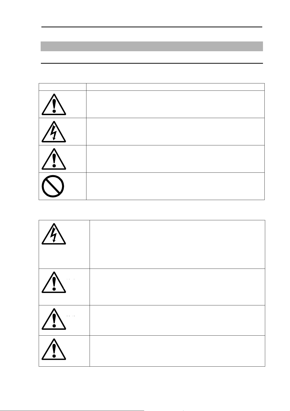
Pictograms used in this Service Manual
The following pictograms are used in this manual. The meaning of each symbols shall be well
understood and the maintenance and inspection shall be carried out.
Symbol Meaning
Mark for warning
Warning
This mark denotes that there is a risk of death or serious injury when
dealt with incorrectly.
Mark for danger of high voltage
This mark denotes that there is a risk of death or serious injury due to
electric shock when dealt with incorrectly.
Mark for caution
Caution
This mark denotes that there is a risk of slight injury or damages of
devices when dealt with incorrectly.
Mark for prohibition
This mark denotes prohibition of specified conducts. Description of the
prohibition is displayed near the mark.
Precautions on equipment
Be careful of high voltage inside
High voltage, which may risk you life, is used. This high voltage may
remain in the circuit even after the power is switched off. To prevent
contact with the high voltage circuits accidentally, a protective cover or
the label with this mark is provided on the high voltage circuit. When the
inside is to be checked, ensure to switch off the power and to discharge
the residual voltage for safety. An engineer authorized by Koden shall
carry out the inspection and maintenance works.
Power off in the boat
An accidental power-on during works may result in worker’s
Warning
electrification. To prevent such accident in advance, ensure that power
in the boat and on the equipment are switched off. Furthermore, it is
safer to hang a caution tag saying “Under work” near the power switch
of equipment.
Be careful of dust
Inhaled dust may cause respiratory affection. At the time of cleaning the
Warning
inside of equipment, be careful not to inhale dust. Wearing a safety
mask is recommended.
Caution on location of installment
Caution
The equipment shall not be installed at locations which are excessively
damp and suffers from water drops. Otherwise, dew condensation may
occur inside the display screen, and corrosion may occur inside the unit
box.
0093822202-01 iii

For Your Safe Operation KGC-222
r
Measures against static electricity
Caution
Caution
Precautions on handling
Warning
Warning
Static electricity may be generated from the carpet on the floor in the
cabin or clothes made of synthetic fiber, and it may destroy the
electronic components on circuit boards. The circuit boards shall be
handled with appropriate measures against static electricity.
Caution at installation of transduce
Transducer shall be installed at locations where there is no effect by
bubble and noise. Bubble and noise may seriously degrade the
performance of this equipment.
No disassembly or modification of this equipment is allowed. It may lead
to failure, firing, smoking or electric shock. In case of failure, please
contact Koden’s dealers or Koden.
In case of smoking or firing, switch off the power in the boat and of this
equipment. It may lead to firing, electric shock or damages.
Be careful of residual high voltage
High voltage may remain in capacitors for several minutes after
switching off the power. Before inspection of the inside, please wait at
least 5 minutes after switching off or discharge the residual electricity in
an appropriate manner. Then, start the work.
The information displayed on this equipment is not intended to use for
Caution
your navigation. For your navigation, be sure to see the specified
materials.
Please use the specified fuses. If un-specified fuses are used, they may
Caution
cause firing, smoking or damages.
Be sure to submerge the transducer in water before transmission. If
Caution
not, it may be damaged.
iv 0093822202-01

KGC-222 Contents
Contents
Document Revision History .............................................................................................. i
Important Notice .............................................................................................................. ii
For Your Safe Operation ................................................................................................. iii
Contents ........................................................................................................................ v
Introduction .................................................................................................................... vii
System Configuration .................................................................................................... viii
System Configuration (with Junction box) ...................................................................... ix
Pin Assignment of Rear Connector ................................................................................. x
Connection with Junction box (JB-35) ............................................................................ xi
Configuration of Equipment ........................................................................................... xii
External view and dimensions ...................................................................................... xiv
Specifications ............................................................................................................... xvi
Chapter 1 Installation .......................................................................... 1-1
1.1 Items of Caution on Installation ............................................................................ 1-1
Unpacking the components ................................................................................ 1-1
Appearance varification of each unit and accessories ........................................ 1-1
Selection of location for installation .................................................................... 1-1
Laying and Connection of Cable ........................................................................ 1-3
Confirmation after Installation ............................................................................. 1-4
1.2 Installation of Display unit .................................................................................... 1-5
Table mounting ................................................................................................... 1-5
Flush mounting ................................................................................................... 1-6
1.3 Installation of GPS antenna GA-12 ...................................................................... 1-7
Antenna cable layout method ............................................................................. 1-7
Installation of GPS antenna ................................................................................ 1-8
Angle compensation of Antenna ......................................................................... 1-9
Connecting and waterproofing the connector ..................................................... 1-9
Connecting the 60m antenna cable kit CW-394.KIT to GPS antenna .............. 1-10
Installing the bird protector to Antenna unit ....................................................... 1-11
1.4 Wiring ................................................................................................................. 1-12
Chapter 2 Maintenance and Troubleshooting ..................................... 2-1
2.1 Inspection ............................................................................................................... 2-1
2.2 Cleaning ................................................................................................................. 2-1
Display unit ......................................................................................................... 2-1
2.3 If you suspect a trouble .......................................................................................... 2-1
2.4 Error Message ........................................................................................................ 2-2
2.5 Initialize .................................................................................................................. 2-4
0093822202-01 v

Contents KGC-222
Initialization of KGC-222 is performed. ............................................................... 2-4
Chapter 3 Detail of the serial output data ............................................ 3-1
3.1 Output data format ............................................................................................... 3-1
3.2 Details of the output data format .......................................................................... 3-1
3.3 Output data specification ..................................................................................... 3-1
3.4 Details of output sentences ................................................................................. 3-1
Chapter 4 Technical references ........................................................... 4-1
4.1 Maintenance parts list .......................................................................................... 4-1
4.2 Exploded view drawing ........................................................................................ 4-2
4.3 Block diagram ...................................................................................................... 4-3
vi 0093822202-01

KGC-222 Introduction
Introduction
KGC-222 is a GPS compass.
Through the use of GPS satellites, it outputs the heading of vessel with a high degree of
accuracy by calibrating the phase difference of two GPS antennas.
The main features of this unit are as follows:
KGC-222 consists of two main components, Display and Antenna.
Display unit has processor, receiver and LCD display built-in.
KGC-222 has internal electronic compass as backup sensor.
This enables the backup sensor to output heading even if the GPS signals are interrupted
in such case as the vessel passing under a bridge.
KGC-222 can also output pitch / roll and heaving data.
When KGC-222 is used with an echo sounder with heaving compensation function, you
can obtain stable sea bottom without effect from heaves and waves.
It has 3 heading data output ports. Up to 5 ports will be available with connecting an
optional junction box.
0093822202-01 vii
System Configuration KGC-222
System Configuration
Connection diagram
Legend
Standard configuration
Option
Owner supply
GPS antenna GA-12
With Bird protector
緊急
With mounting bracket and vinyl cover
POWER Connector
CW-266-1.8M
Display unit KGC-222
CW-392-15M
CW-392-15M
DATA 3 Connector
DATA 3 Connector
CW-373-5M
CW-376-5M
KBG-3
Software virsion:
KM-E34G and after
is required.
Chart Plotter
Echo sounder
Red +
10.8 to 31.2VDC
Black -
DATA 2 Connector
CW-373-5M
CW-376-5M
DATA 1 Connector
CW-373-5M
CW-376-5M
Marine radar
Chart Plotter
Echo sounder
Auto pilot
Marine radar
Chart Plotter
Echo sounder
Auto pilot
viii 0093822202-01

KGC-222 System Configuration
System Configuration (with Junction box)
Connection diagram
With mounting bracket and vinyl cover
Legend
Standard configuration
Option
Owner supply
Display unit KGC-222
GPS Antenna GA-12
CW-392-15M
CW-392-15M
緊急
With Bird protector
KBG-3
Software virsion:
KM-E34G and after
is required.
POWER Connector
CW-266-1.8M
CW-376-5M
Red +
Black -
Junction Box
JB-35
10.8 to 31.2VDC
DATA 3 Connector
DATA 3 Connector
CW-373-5M
CW-376-5M
DATA 2 Connector
CW-373-5M
CW-376-5M
DATA 4 Connector
CW-376-5M
DATA 5 Connector
CW-376-5M
DATA 1 Connector
CW-376-5M
Chart Plotter
Echo sounder
Marine radar
Chart Plotter
Echo sounder
Auto pilot
Marine radar
Chart Plotter
Echo sounder
Auto pilot
Marine radar
Chart Plotter
Echo sounder
Auto pilot
Marine radar
Chart Plotter
Echo sounder
Auto pilot
0093822202-01 ix
System Configuration KGC-222
Pin Assignment of Rear Connector
The pin assignment is viewed from the rear of the Display unit.
Power Input
3
1
2
POWER
DATA IN/OUT
1
6
2
3
DATA 1/2/3
Connector acceptable: LTWBD-06BFFA-L18
Caution: KGC-222 Compass has 12V power on PIN 6 of each DATA connector.
For reference:
Wire color of CW-376-5M
1 POWER+
2 F.GND
3 POWER-
1 GND
5
4
2 TX+
3 TX4 RX+
5 RX6 +12V (Maximum 300 mA)
Caution: The maximum current capacity
is 300 mA in total, then it should not
exceed.
Take care that the grand total of each
connector does not exceed 300 mA.
Please pay attention not to accidentally connect 12V to other equipment
NMEA input. Equipment damage may occur.
1 Blue+Shield
2 White
3 Red
4 Orange
5 Black
6 Green
x 0093822202-01
KGC-222 System Configuration
A
A
A
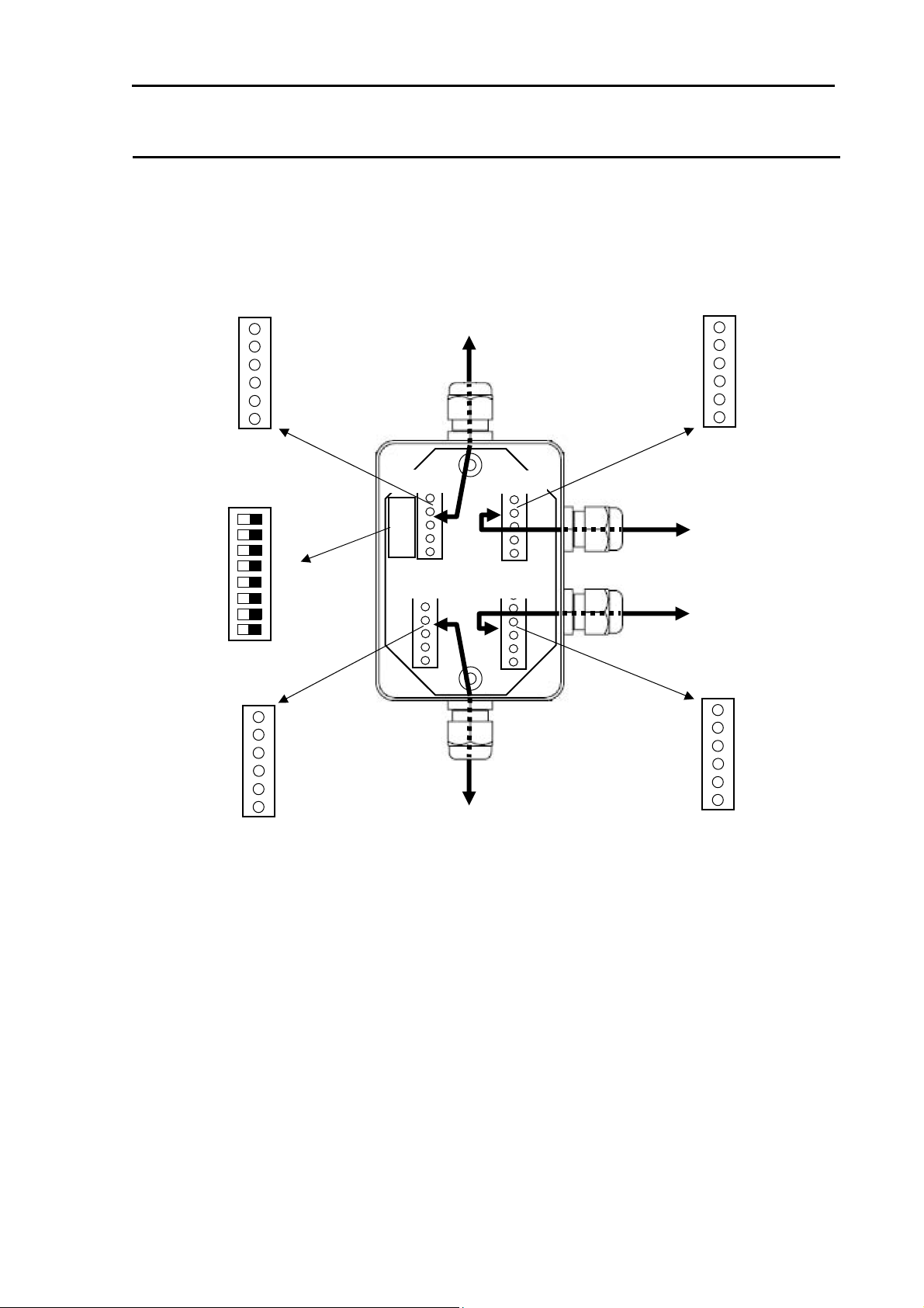
Connection with Junction box (JB-35)
To extend the ports, connect the junction box (JB-35) to the data connectors as shown in the
figure below.
Set the DIP switch (S1) as shown in the figure below.
Wire the cables with the CW-376-5M (option) as shown in the following color chart.
+12V
TXTX+
RXRX+
GND
Green
Black
Orange
Red
White
Blue+Shield
ON OFF
ALL OFF
1 2 3 4 5 6 7 8
NC
TXTX+
RXRX+
GND
Green
Black
Orange
Red
White
Blue+Shield
To DATA1 of Display unit
CW-376-5M
JB-35
MASTER
S1
SLA VE3
SLA VE1
SLA VE2
ssigned to DATA1
To external equipment
Green
Black
Orange
Red
White
Blue+Shield
ssigned to DATA4
To connection equipment
ssigned to DATA5
To connection equipment
Green
Black
Orange
Red
White
Blue+Shield
NC
TXTX+
RXRX+
GND
NC
TXTX+
RXRX+
GND
0093822202-01 xi
Configuration of Equipment KGC-222
r
A
Configuration of Equipment
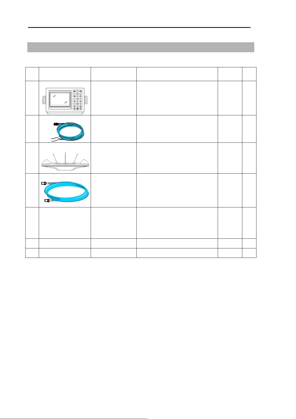
Standard Equipment Configuration List
No. Name of item Type Remark
1 Display unit KGC-222.MU
With mounting bracket and
vinyl cover
Weight/
Length
0.87 kg 1
2
DC power cable
CW-266-1.8M With a 3-pin connector and one
1.8m 1
end plain
3 GPS antenna
GA-12 With bird protecto
1
4
ntenna cable
CW-392-15M 3D-2V
With BNC connectors on the
15m 2
both sides
5
Installation
material
TPT5 X 20U
T.5X20MMX10M
10M [gray]
B8X25U
Truss tapping screw (2)
Self-bonding tape (1)
PVC tape (1)
Hexagon bolt for antenna
1
installation (4)
6 Operation Manual KGC-222.OM.E English 1
Qty
set
7 Cautionary Note KGC-222.RM.E English 1
xii 0093822202-01
 Loading...