

Koden KDS-6000BB Installation Manual


KDS-6000BB Revision History
No.
Doc. No-Rev. No.
Revised Date
(Y/M/D)
Revised Content
0
0092660002-00
2014/09/29
First edition
1
0092660002-01
2014/12/05
System Configuration, Configuration of
Equipment, Chapter 1
2
0092660002-02
2015/03/16
System Configuration, Configuration of
Equipment, Chapter 1
3
0092660002-03
2015/07/14
Chapter 1
4
0092660002-04
2015/11/20
System Configuration, Configuration of
Equipment
5
0092660002-05
2016/03/17
Configuration of Equipment, External View,
Chapter 1
6
0092660002-06
2017/11/02
Chapter 3
7
8
9
10
KDS-6000BB Installation Manual
Doc No: 0092660002
Document Revision History
Document No. Revised Version Norm
When part of the document needs to be revised, the document has advanced revision number.
The document No. is indicated at the lower right side on the cover and at the left or right side of the
region of each page.
© 2014-2017 Koden Electronics Co., Ltd. All rights reserved.
No part of this publication may be reproduced, transmitted, translated in any form by any means
without the written permission of Koden Electronics Co., Ltd. The technical descriptions contained in
this publication are subject to change without notice. Koden assumes no responsibility for any errors,
incidentals or consequential damages caused by misinterpretation of the descriptions contained in this
publication.
0092660002-06 i

Important Notice KDS-6000BB
Important Notice
• For copy and transcription of this Installation Manual (hereinafter referred to as this
manual), permission from Koden is needed. Koden prohibits the un-authorized copy and
transcription of this manual.
• If this manual is lost or damaged, consult a dealer of Koden or Koden.
• The specification of the products and the contents in this manual are subject to change
without notice.
• The contents displayed on the menu of product may be different from the expression of this
manual. The fonts and shapes of the keys and menus in the illustration may differ from the
actual ones, and some parts may be omitted.
• Koden is not liable for damages and troubles arisen from misunderstanding of the contents
in this manual.
• Koden is not liable for any damages caused by earthquake, lightning, wind and flood
damage and fire for which Koden is not responsible, and actions by third parties, other
accidents, customer’s unintended error/abuse and the use under other abnormal
conditions.
• Koden is not liable for damages of accompaniment (change/loss of memorized content,
loss of business profit, stop of business) arisen from use or failure of our products.
• If the stored data are changed or lost, irrespective of causes of troubles and damages,
Koden is not liable for them.
• Koden is not liable for any damages arisen from malfunction caused by combination of
software and connected equipment in which Koden is not engaged.
ii 0092660002-06
KDS-6000BB For Your Safe Operation
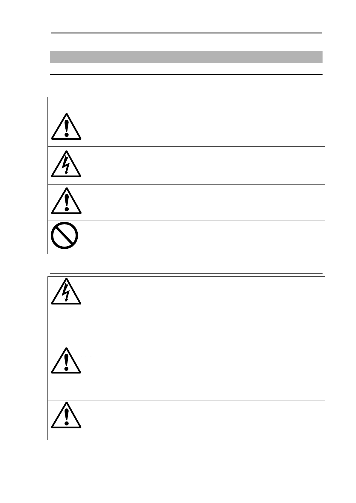
Symbol
Meaning
Mark for warning
This symbol denotes that there is a risk of death or serious injury when
not dealing with it correctly.
Mark for danger of high voltage
This symbol denotes that there is a risk of death or serious injury caused
by electric shock when not dealing with it correctly.
Mark for caution
This symbol denotes that there is a risk of slight injury or damage of
device when not dealing with it correctly.
Mark for prohibition
This symbol denotes prohibition of the specified conduct. Description of
the prohibition is displayed near the mark.
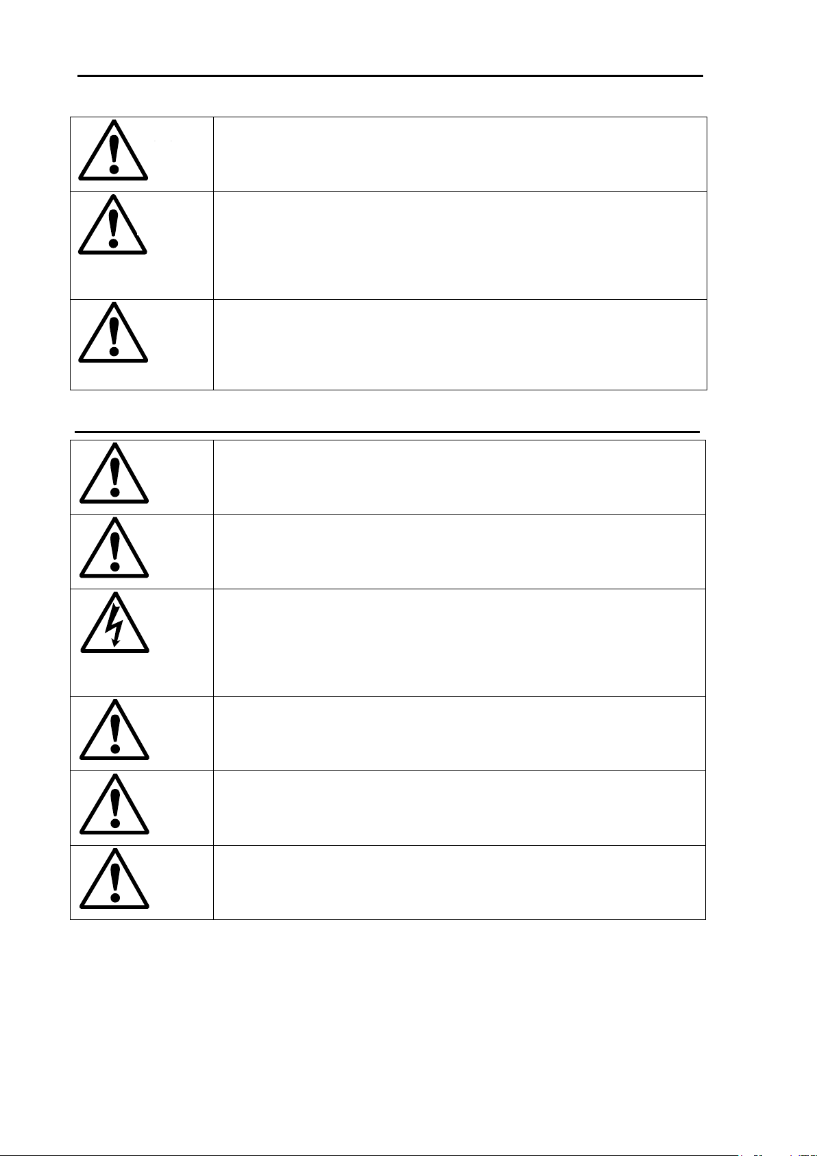
Be careful of high voltage inside
A high voltage, which may risk your life, is used. This high voltage
remains in the circuit after you have powered off switch. To prevent
touching the high voltage circuit inadvertently, the hard cover is
provided to the high voltage circuit and the high voltage caution label is
affixed. Ensure to power off switch for your safety and discharge the
electricity remaining in the capacity before starting to check. An
engineer authorized by our company should inspect and maintain.
Be sure to power off in the boat
If the power switch is inadvertently powered on during work, you will be
electrified. To prevent such accident from occurring, ensure to power off
in the boat and the power of equipment. Furthermore, it is safer to hang
the caution tag described as [Under Work] near the power switch of
equipment.
Be careful of dust
Inhaling dust may cause A respiratory disease. When cleaning the
inside of equipment, be careful not to inhale dust. Wearing a safety
mask is recommended.
Warning
Warning
Caution
Warning
For Your Safe Operation
Symbol used in this Installation Manual
The following pictograms are used in this manual. The meaning of each symbols shall be well
understood and the maintenance and inspection shall be carried out.
Caution items on equipment
0092660002-06 iii
For Your Safe Operation KDS-6000BB
Caution on location of equipment
Do not install the equipment where it is excessively damp and suffers
from excessive water drops.
Measures against static electricity
The static electricity may be generated from the carpet on the floor in
the cabin or clothes made of synthetic fiber. The static electricity may
destroy the electronic parts on the circuit board. Handle the circuit
board, taking the measure of static electricity free.
Caution at installation of a transducers
Install the transducer at the location where it is not affected by bubble
and noise The bubble and noise seriously degrade the performance of
this unit.
Do not disassemble or modify. It may leads to trouble, fire, smoking or
electric shock. In case of trouble, contact our dealer or our company.
In case of smoke or fire, boat power off and the power of this unit. It may
cause fire, electric shock or damage.
Be cautious of remaining high voltage
A high voltage may remain in the capacitor for several minutes after you
have powered off. Before inspecting inside, wait at least 5 minutes after
powering off or discharge the remaining electricity in an appropriate
manner. Then, start the work.
The information displayed in this unit is not provided directly for your
navigation. For your navigation, be sure to see the specified material.
Use the specified fuse. If un-specified fuse is used, it may cause a fire,
smoke or damage.
Whenever transmitting, be sure to submerge the transducer in water
first. If transmitted without submerging the transducer, it may be
damaged.
Caution
Caution
Caution
Warning
Warning
Caution
Caution
Caution
Cautions on handling
iv 0092660002-06

KDS-6000BB Contents
Contents
Document Revision History ............................................................................................................. i
Important Notices ............................................................................................................................ ii
For Your Safe Operation ................................................................................................................ iii
Contents ......................................................................................................................................... v
System Configuration ................................................................................................................... vii
Configuration of Equipment ......................................................................................................... viii
External View ............................................................................................................................. xiv
Specification ............................................................................................................................ xvii
Chapter 1 Installation .................................................................................................................. 1-1
1.1 Installation precautions .......................................................................................................... 1-1
1.1.1 Unpacking of components .......................................................................................... 1-1
1.1.2 Appearance verification of each unit and accessories ................................................ 1-1
1.1.3 Selection of location for installation ............................................................................. 1-1
1.1.4 Laying and connection of cables ................................................................................. 1-2
1.1.5 Confirmation after installation ..................................................................................... 1-2
1.2 Installation of KDS-6000BB Display unit ................................................................................ 1-3
1.3 Installation of KDC-6000BB Processor unit ........................................................................... 1-3
1.4 Installation of an Operation unit ............................................................................................. 1-4
1.4.1 Desk-top installation of Operation unit ....................................................................... 1-4
1.4.2 Flush-mount installation of Operation unit ................................................................. 1-6
1.4.3 Installation of TD position alarm / Ext. Sync. Box ....................................................... 1-7
1.5 Installation of Hull unit ............................................................................................................ 1-8
1.5.1 Installation location of Hull unit ................................................................................... 1-8
1.5.2 Maintenance space for TD tank ................................................................................. 1-9
1.5.3 Installation conditions for a TD tank ......................................................................... 1-10
1.5.4 Example of installation of the TD tank ..................................................................... 1-11
1.5.5 Assembly of Hull unit ................................ ................................ ............................... 1-13
1.6 Wiring .................................................................................................................................. 1-22
1.6.1 Connection of cables to Processor unit ................................................................... 1-22
1.7 List of input/output sentences .............................................................................................. 1-35
1.7.1 Input sentences ....................................................................................................... 1-35
1.7.2 Output sentences ..................................................................................................... 1-35
Chapter 2 Adjustment ................................................................................................................. 2-1
2.1 Setup of frequency of Transducer unit ................................................................................... 2-1
2.1.1 Setting of frequency ................................................................................................... 2-1
2.2 Setting of gain of Transducer unit .......................................................................................... 2-1
2.3 Setup of TX power ................................................................................................................. 2-2
0092660002-06 v

Contents KDS-6000BB
2.3.1 Display of TX power menu ....................................................................................... 2-2
2.4 Train correct ........................................................................................................................ 2-3
Chapter 3 Maintenance ............................................................................................................... 3-1
3.1 Inspection .............................................................................................................................. 3-1
3.2 Cleaning ................................................................ ................................................................ 3-1
3.2.1 Monitor/Processor units ............................................................................................. 3-1
3.2.2 Hull unit ...................................................................................................................... 3-2
3.3 Fuse replacement .................................................................................................................. 3-2
3.4 Diagnostics of troubles .......................................................................................................... 3-2
3.4.1 Necessary information for requesting repair .............................................................. 3-2
3.4.2 System check ............................................................................................................ 3-3
3.4.3 Setting at factory ........................................................................................................ 3-4
3.4.4 Other maintenance menu .......................................................................................... 3-4
3.4.5 Update of programs ................................................................................................... 3-6
3.5 If you suspect a trouble ....................................................................................................... 3-10
vi 0092660002-06
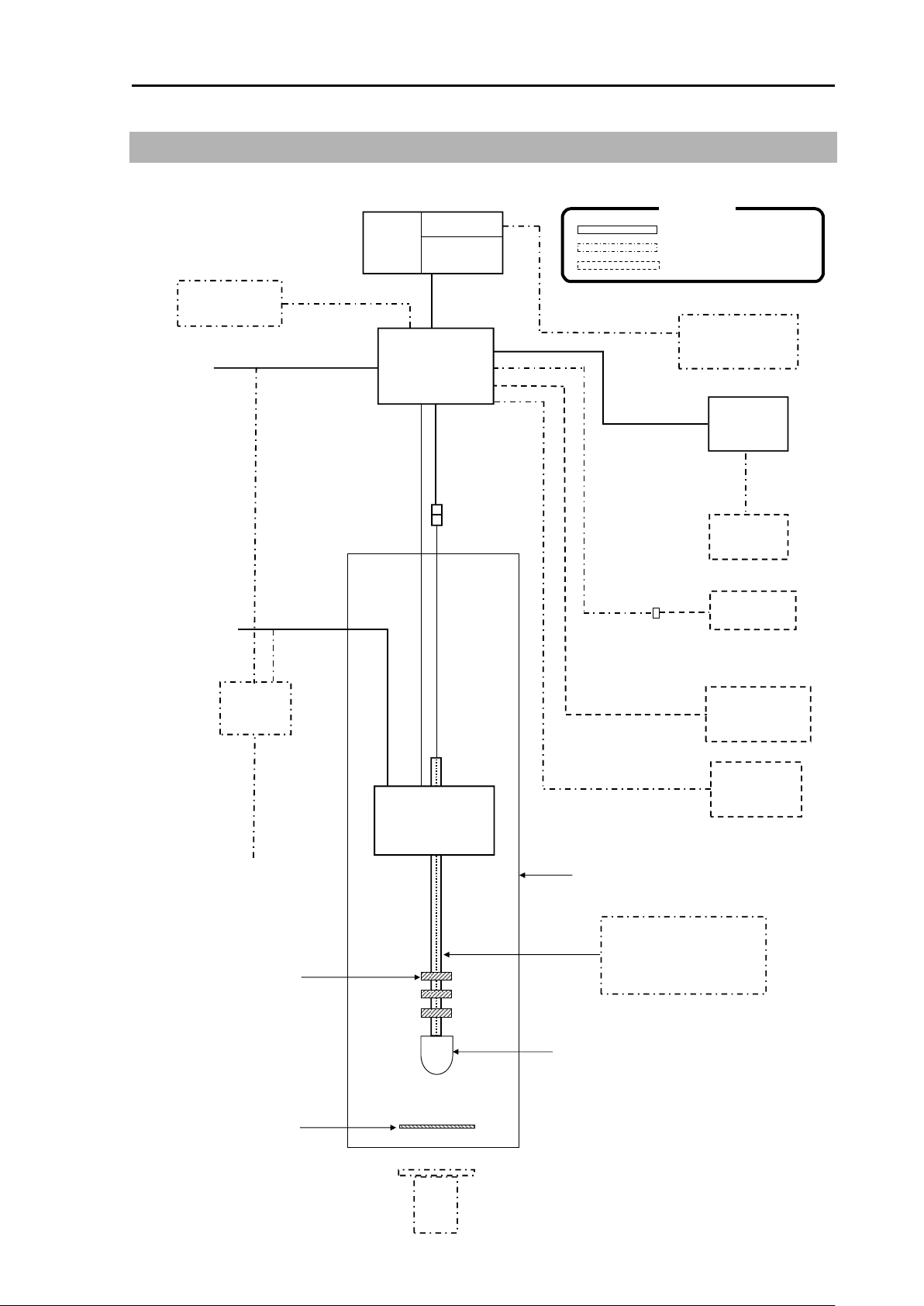
KDS-6000BB System Configuration
Onboard DC
power supply
10.8 to
31.2VDC
J8 (6P)
Remote controller
RCW-14
Display unit
17 inch LCD monitor
is acceptable
Echo sounder
GPS Compass
NMEA Converter
TD shaft
ESR-1504(1411mm)
/ESR-160 32679C-2(1681mm)
/ESR-160 32679C-3(1981mm)
/ESR-160 (40φ-4t-3000mm)
Shaft guide
ESR-1510
ESR-1511
For ESR-1507
Hull unit
DHU-630
TD tank
ESR-1506
/30927C-2
/30927C-3
/ESR-1507
/FRPTD tank set
_G16ELA0010
Gum packing
ESR-1512
Transducer unit
DHU-6302
with 10m cable
Onboard AC
power supply
100/115VAC
200/230VAC
AC power cable
VV-2D8-3M
CW-373-5M
CW-376-5M
POWER (3P)
J6 (8P)
J2 (12P)
J1 (5P)
CW-259-2M
Hull unit
control cable
CW-593-20M
TD position
alarm / Ext.
Sync. Box
JB-36
DOU-620
DOU-620R
(with RCW-14)
CW-576-0.5M
J5 (10P)
External monitor
D-sub15P
Cable for external
monitor
(CW-560-2M is
acceptable)
CW-275-10M
Transducer unit
extension cable
CW-590-15M
18P female
18P male
Processor unit
DPU-610
DPU-610ST
(Sona-ToneTMmodel)
J7 (16P)
15P
Onboard DC
power supply
10.8 to
31.2VDC
Trigger In/Out
CW-413-5M
CW-412-5M
Hull unit
DHU-6301
Power rectifier
PS-010
Operation
unit
External speaker
NP-108
DPU-610ST
(Sona-ToneTMmodel)
Cable for
external speaker
Standard configuration
Option
Owner supply
Legend
System Configuration
Connection Diagram
0092660002-06 vii
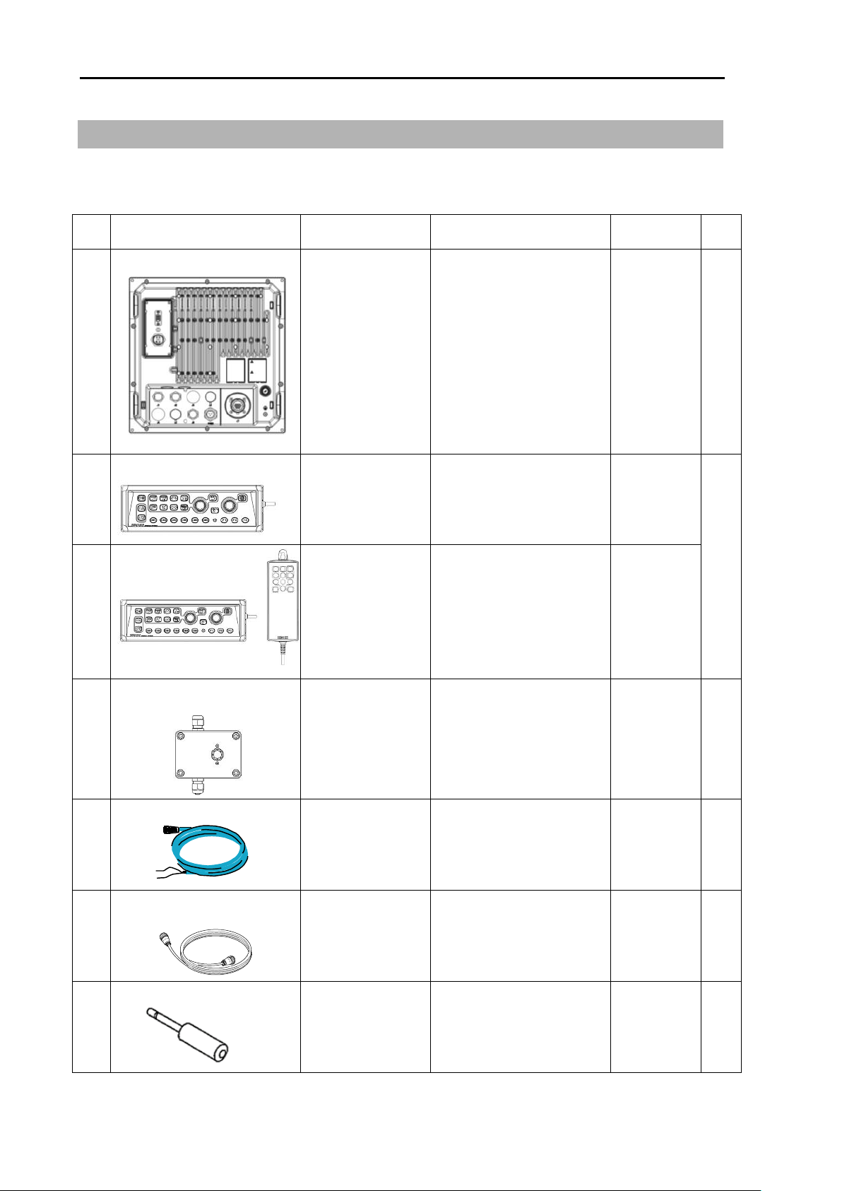
Configuration of Equipment KDS-6000BB
No
Name of item
Type
Remark
Weight/
Length
Qty
1
Processor unit
DPU-610/
DPU-610ST
(Sona-ToneTM
model)
No display unit
VGA output
5.1kg
1
2-1
Operation unit
DOU-620
With mounting bracket
and 5m cable
1.1kg
1
2-2
Operation unit
DOU-620R
With mounting bracket,
5m cable and Remote
controller (RCW-14 with
5m cable)
DOU-620
1.1kg/
RCW-14
0.31kg
3
TD position alarm / Ext.
Sync. Box
JB-36
With 5m cable
(CW-413-5M/With 5 pin
connector and one end
plain)
5m
1
4
DC power cable
CW-259-2M
With 3 pin connector and
one end plain
2m 1 5
Transducer unit extension
cable
CW-590-15M
With a 18 pin connector
and a 12 pin water
resistant connector
15m 1 6
Audio system plug
MP-105LC-RoHS
For Sona-ToneTM model
1
Configuration of Equipment
Standard Equipment Configuration List
a. DPU-610/610ST (Processor unit), DOU-620/620R (Operation unit)
viii 0092660002-06
KDS-6000BB Configuration of Equipment
No
Name of item
Type
Remark
Weight/Length
Qty
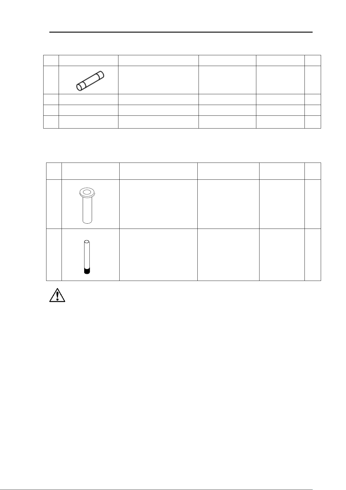
7
Fuse
F-7161-10A/N30C-125V
Cylinder (ø 6.4x30)
Normal fusion type
for main power
3
8
Operation manual
KDS-6000BB.OM.E
English
1
9
Quick Reference
KDS-6000BB.QR.E
English
1
10
Installation manual
KDS-6000BB.IM.E
English
1
No.
Name of item
Type
Remark
Weight/Length
Qty
1
TD tank
ESR-1506 (PVC) 1230mm
30927C-2 (PVC) 1500mm
30927C-3 (PVC) 1800mm
ESR-1507 (FRP) 1500mm
Select according to
equipment.
*Refer to Option list.
9.0kg
11.0kg
13.0kg
12.0kg
1
2
TD shaft
ESR-1504
ESR-160_32679C-2
ESR-160_32679C-3
ESR-160_40φ-4t-3000mm
Select according to
equipment.
*Refer to Option list.
1411mm
1681mm
1981mm
3000mm
1
Caution: TD tank and TD shaft are options.
b. TD tank / TD shaft
0092660002-06 ix
Configuration of Equipment KDS-6000BB
×8
×8
×8
×8
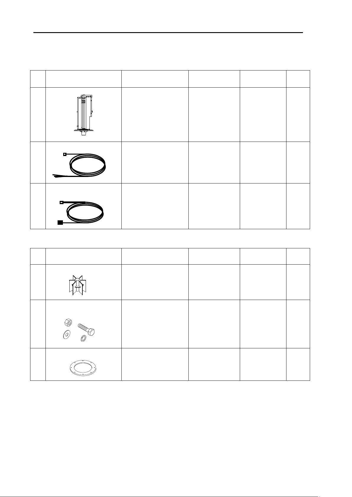
No
Name of item
Type
Remark
Weight/Length
Qty
1
Hull unit
DHU-6301
17.0kg
1
2
DC power cable
CW-275-10M
Cable is built
into the Hull unit
10m
1
3
Hull unit
control cable
CW-593-20M
Cable is built
into the Hull unit
20m
1
d. DHU-6302 (Transducer unit)
Package 2-1
No
Name of item
Type
Remark
Weight/Length
Qty
1
Shaft guide
ESR-1510
3
2
Bolt set
SUS-M16-55-Assy
(M16x55L, 2W16U,
SW16U, N16U)
EACH
8
3
Gum packing for flange
ESR-1512
Gum 1
c. DHU-6301 (Hull unit)
Package 1-1
x 0092660002-06
KDS-6000BB Configuration of Equipment
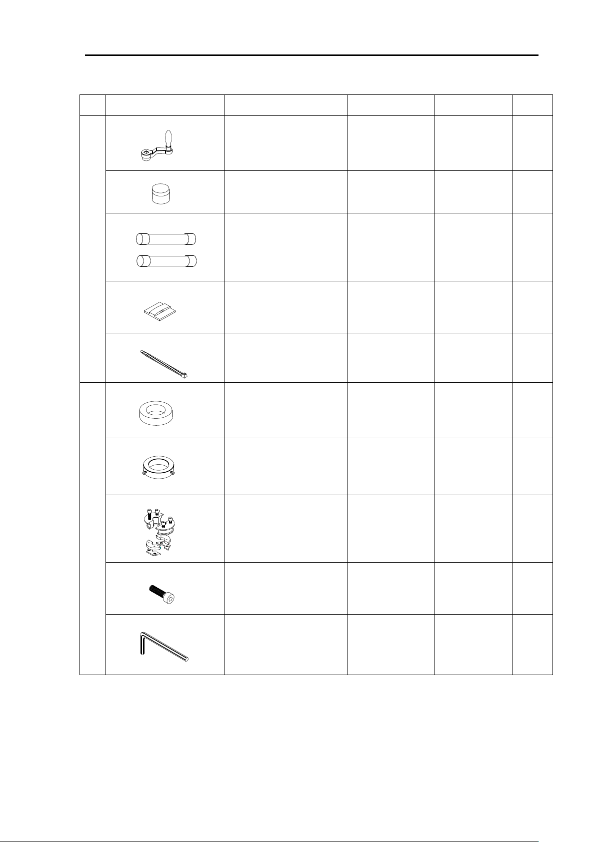
No
Name of item
Type
Remark
Weight/Length
Qty
4
Crank handle
OB-03
1
Grease
100g
1
Fuse
F-7161-4A
F-7161-8A
At input of 12 V
At input of 24 V
EACH
3
ANP base
ANP-1
2
Binding Band
AB-100-1000
2
5
Damper
34924D
1
Fixing collar
32681D
2
Shaft cap
34378D
1
Cap bolt
CB4X10U
4
HEX rod wrench
1.5mm ×1
2.5mm ×1
3.0mm ×1
EACH
1
1 SET
4A
8A
0092660002-06 xi

Configuration of Equipment KDS-6000BB
No
Name of item
Type
Remark
Weight/Length
Qty
1
Transducer unit
DHU-6302
With 10m cable
(With 18 pin
water resistant
connector)
9.0kg
1
2
Bath cork
Bath cork (White) 50g
50g
1
HEX rod wrench
3.0mm ×1
5.0mm ×1
EACH
1
Package 2-2
Caution: Don’t carry the Transducer unit (DHU-6302) by holding its cable. Such
xii 0092660002-06
manner may cause breakage of the equipment.

KDS-6000BB Configuration of Equipment
No
Name of item
Type
Remark
1
Remote controller
RCW-14
With 5m cable, (Assembled the
connection cable into the Operation unit)
2
TD tank
(For *xxxx mm of TD
shaft)
*TD shaft length
ESR-1506
PVC, 1230mm (For 1411mm of TD shaft)
30927C-2
PVC, 1500mm (For 1681mm of TD shaft)
30927C-3
PVC, 1800mm (For 1981mm of TD shaft)
ESR-1507
FRP, 1500mm
FRP TD tank set
(Including Shaft guide)
ESR-1507(1), ESR-1510(2),
ESR-1511(2)
3 Shaft guide
ESR-1510
ESR-1506 / 1507
ESR-1511
ESR-1507 (For FRP TD tank)
4
Power rectifier
PS-010
With 2 pieces of 5A fuse
5
AC power cable
VV-2D8-3M
Both ends plain
6
Connecting cable
CW-372-5M
5m
With 5 pin water resistant connector and
one end plain
CW-373-5M
5m
6 pin water resistant connectors at both
ends
CW-376-5M
5m
With 6 pin water resistant connector and
one end plain
Cable for external monitor
CW-576-0.5M
0.5m
With 10 pin water resistant connector and
D-Sub connector
CW-560-2M
2m
D-Sub 15 pin connectors at both ends
7
Junction box
JB-35
1 input, 3 outputs with CW-376-5M
8
TD shaft
ESR-1504
1411mm
32679C-2
ESR-160_1681mm
32679C-3
ESR-160_1981mm
40φ-4t-3000mm
ESR-160_3000mm
9
Monitor
17inch LCD Monitor
With power cable and signal cable
10
External speaker
NP-108
With 5m cable
(For Sona-ToneTM model)
Option List
0092660002-06 xiii
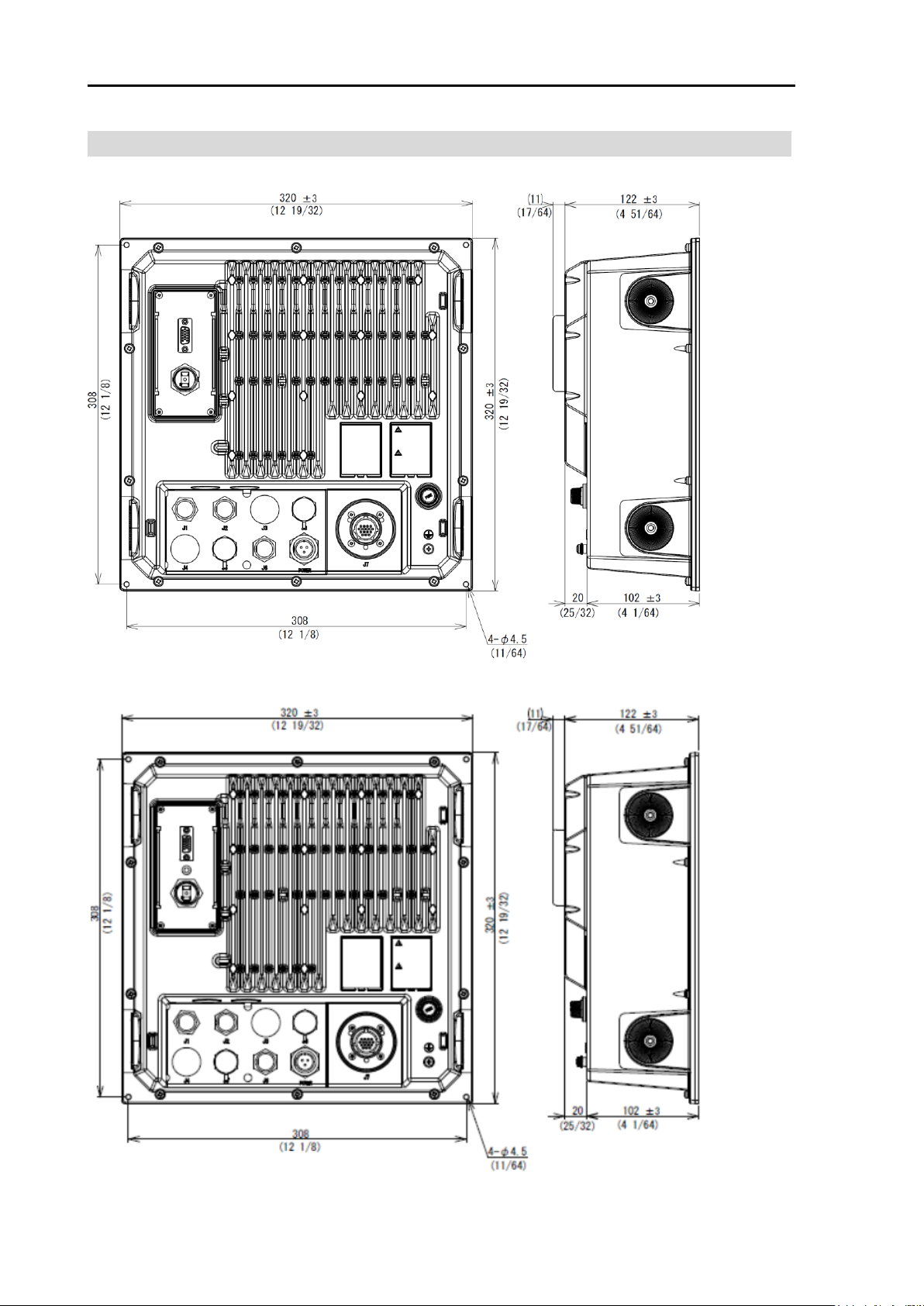
External View KDS-6000BB
Unit: mm (inch)
External View
Processor unit (DPU-610)
Processor unit (DPU-610ST) (Sona-ToneTM model)
Processor unit (DPU-610ST) (Sona-ToneTM model)
xiv 0092660002-06
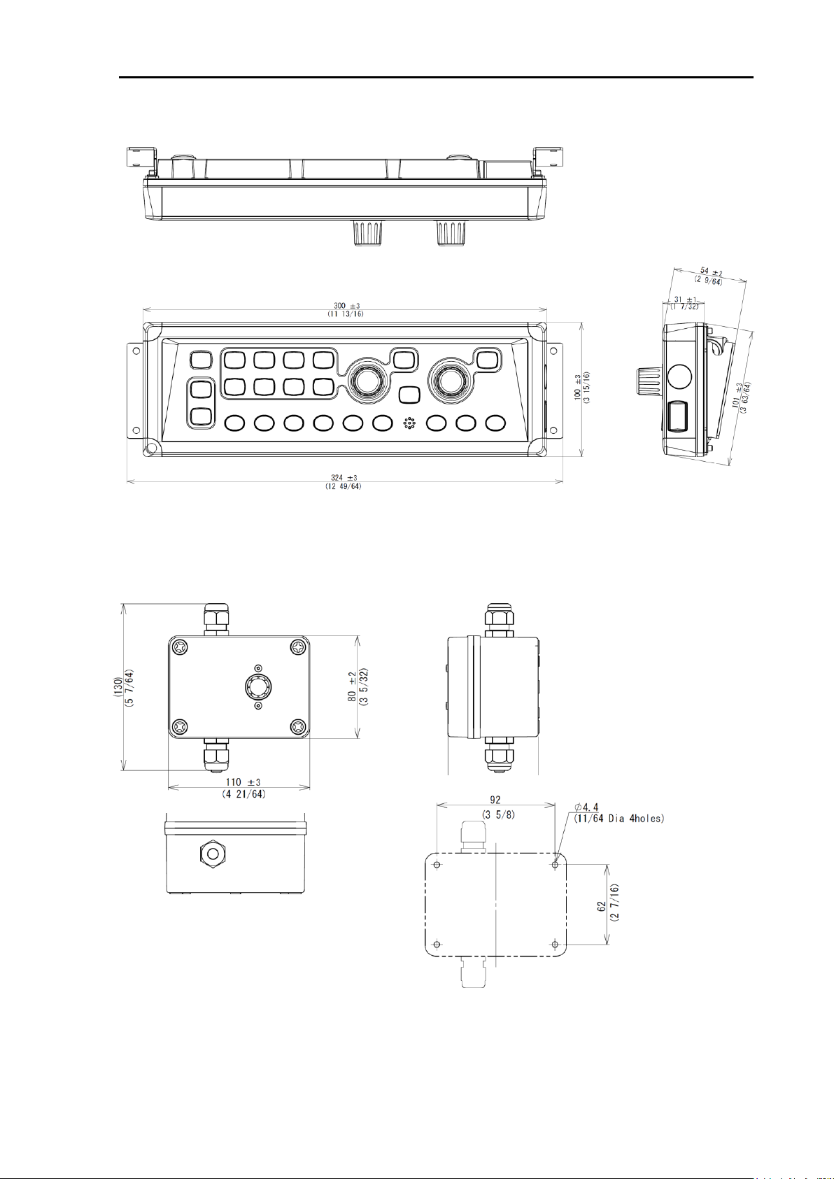
KDS-6000BB External View
Unit: mm (inch)
Installation dimensions
Operation unit (DOU-620)
TD position alarm / Ext. Sync. Box (JB-36)
0092660002-06 xv
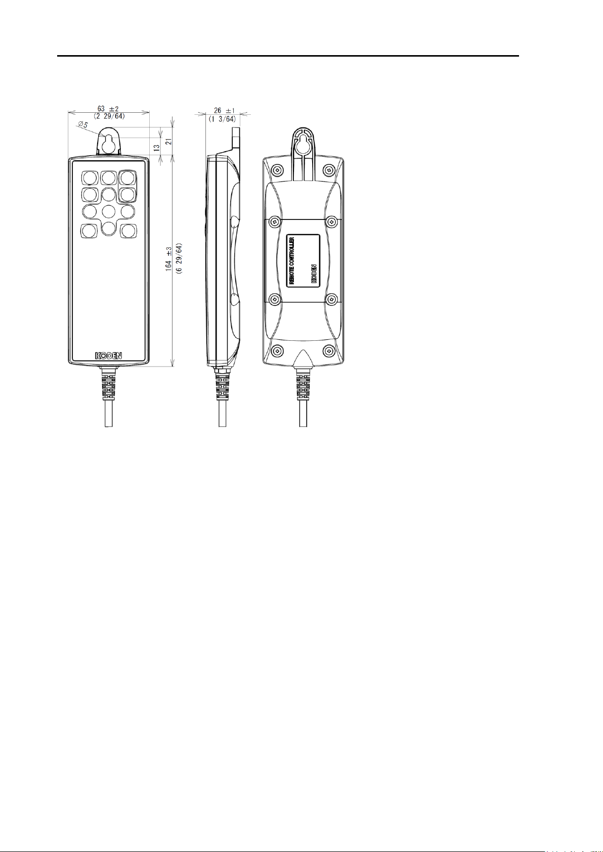
External View KDS-6000BB
Unit: mm (inch)
Remote controller (RCW-14) (Optional)
xvi 0092660002-06
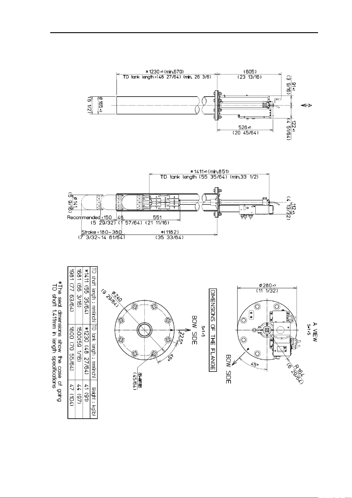
KDS-6000BB External View
Unit: mm (inch)
Hull unit (DHU-630)
0092660002-06 xvii
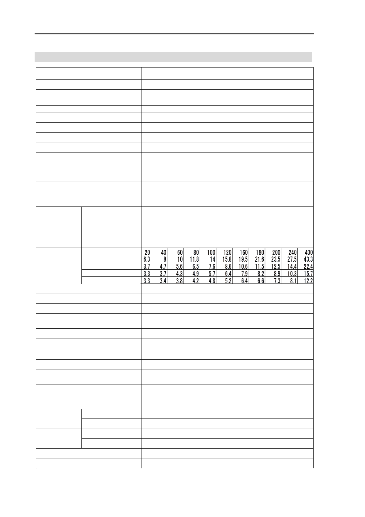
Specification KDS-6000BB
Sonar mode
Bottom scan mode
Scanning range (m)
Scanning time (sec.) 5º step
Scanning time (sec.) 10º step
Scanning time (sec.) 15º step
Scanning time (sec.) 20º step
Fore, Back, Left, Right
Processor unit
Hull unit
Processor unit
Hull unit
360º Scanning time
(extracts)
Processor unit
Operation unit
Hull unit
DPU-610
DOU-620
DHU-630
Point corner
TD stroke
Basic ranges
Range units
Scanning
sector
angles
Water protection
Bearing center
Presentation modes
Off-center
Target lock
Presentation colors
Reverse, Horizontal, Horizontal + vertical, Marker + horizontal,
Marker + horizontal + vertical
Item
Model
5°step: 5°, 25°, 45°, 85°, 125°, 165°, 205°, 360°
10°step: 10°, 30°, 50°, 90°, 130°, 170°, 210°, 360°
15°step: 15°, 45°, 75°, 105°, 135°, 165°, 225°, 360°
20°step: 20°, 60°, 100°, 140°, 180°, 220°, 260°, 360°
Power supply
8°to 12°
Total1: input / output
10.8 to 31.2 VDC
10.8 to 31.2 VDC
m, ft, fm, l.fm
NMEA0183
DBT、DPT、GGA、GLL、MTW、RMC、TLL、VTG、ZDA
Display resolution
Output power (RMS)
Output frequency
Tilt angle
70 W or less ( 24 VDC)
70 W or less ( 24 VDC)
Output data format and sentences
-15 °C to + 55 °C
16 colors, 8 colors
TVG, Color rejection, Dynamic range, Compass display, Pulse width, Output Power
Control, Noise rejection, A-scope, CM key, Frequency bandwidth, Image correction,
Bearing display, TD auto up, etc.
Input data format and sentences
NMEA0183
GGA、GLL、HDG、HDM、HDT、RMC、VTG、ZDA
Functions
Language
NMEA ports
Operating temperature
Power consumption
Content
1.5 kW
130 to 210 kHz ( 0.1 kHz step)
150 to 380 mm (Recommended value 150 mm)
640 x 480 (VGA)
Any monitor with VGA resolution (Owner supplied)
KDS-6000BB
+5° to -90° (1°step)
ー
10 to 1000 (m), 30 to 3000 (ft), 10 to 600 (fm), 10 to 700 (I.fm)
(8 ranges can be set to users choice)
Display size and type
3°step: 3°, 27°, 45°, 63°, 93°, 117°, 147°, 177°
5°step: 5°, 25°, 45°, 65°, 95°, 115°, 145°, 175°
1°step
English, Japanese, Korean, Traditional Chines, Vietnamese, Spanish, Thai and etc.
Sonar, Off-center, Bottom scan, Echo sounder
Specification
xviii 0092660002-06

KDS-6000BB Chapter 1 Installation
Chapter 1 Installation
1.1 Installation precautions
In order to obtain the maximum performance of the Digital Sonar, this Digital Sonar should be
installed by a qualified engineer in charge of installation and maintenance. Installation
procedures include the following:
(1) Unpacking of components
(2) Inspection of composition units, spare parts, accessories and installation materials.
(3) Checking of supply voltage and current capacity.
(4) Selection of location for installation.
(5) Installation of Display unit, Processor unit, Operation unit and Hull unit.
(6) Attachment of accessories.
(7) Planning and implementation of cable lying and connection.
(8) Coordination after installation.
1.1.1 Unpacking of components
Unpack the components and check that all the items correspond with the description of the
packing list. When a discrepancy or damage has been found, contact the dealer you
purchased of our sales company.
1.1.2 Appearance verification of each unit and accessories
Inspect the appearance of each components and accessories and check that no dents or
damages exist.
If any dents or damages exist and they are believed to be caused by accident during
transportation, contact the transportation and insurance company and consult our sales
company or our dealer nearest to you.
1.1.3 Selection of location for installation
In order to obtain the maximum performance of the unit, it is necessary to install in
consideration of matters described below:
(1) The Processor unit is not waterproof. Do not set it up in the place where water splashes.
(2) Keep enough space for maintenance for the Processor unit and the Hull unit. Especially,
secure enough space at the rear panel where many cables are connected.
(3) The Processor unit, Operation unit and an external monitor shall be set up within the
distance the connection cables are not too stretched.
(4) Keep the equipment as far away from wireless transmitter/receivers as possible.
0092660002-06 1-1
Chapter 1 Installation KDS-6000BB
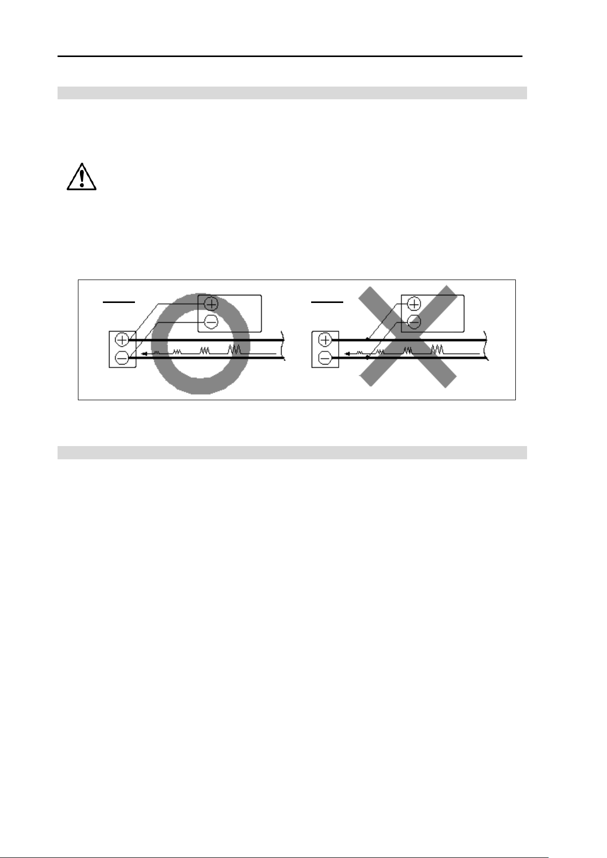
Battery
Good
example
Bad
example
Battery
Display unit, Processor unit or
Display unit, Processor unit
or Hull unit
DPU-610
Noise
Noise
DPU-610
Caution
1.1.4 Laying and connection of cables
(1) Keep the cables related with the Hull unit and the power cable as far away from the cables
of other electronic equipment as possible.
(2) The cabinet of the display unit and the Processor unit shall be securely grounded to the
hull, using the grounding terminal on the rear panel.
All chassis shall be securely grounded as a means of noise
suppression. The – (negative) output is isolated (floating) output.
(3) If you connect the power cable directly to the battery, interference from the other
electronics equipment is expected to be less. (See Fig. 1.1)
Hull unit
or
DHU-630
or
DHU-630
Fig. 1.1 KDS-6000BB Connection of power line
1.1.5 Confirmation after installation
Be sure to confirm the following points before starting. The confirmation is mandatory to
operate the equipment normally:
(1) Is the power voltage in the boat within the appropriate voltage range? Is the current
capacity enough?
(Voltage range: 10.8 VDC to 31.2 VDC measured at the power connector.)
(2) Is the electric current capacity sufficient?
(Power consumption: Processor unit (DPU-610)/70W, Hull unit (DHU-630) /70W)
(3) Is the cabling from the Hull unit correct? Is the wiring shorted?
1-2 0092660002-06
 Loading...