

Page 1

Page 2

Page 3
Page 4

Page 5
GTD-120 Revision History
No.
Doc. No-Rev. No.
Date Revised
(Y/M/D)
Revised Content
0
0093101202-00
2018/01/22
First edition
1
0093101202-01
2018/02/22
Intruduction, Configuration of Equipment,
Chapter 1, Chapter 8, Chapter 13
2
3 4 5
6 7 8
9 10
GTD-120 Operation Manual
Doc No: 0093101202
Document Revision History
Document No. Revised Version Norm
When part of the document needs to be revised, the document has advanced revision number.
The document No. is indicated at the lower right side on the cover and at the left or right side of the
footer region of each page.
© 2018 Koden Electronics Co., Ltd. All rights reserved.
No part of this publication may be reproduced, transmitted, translated in any from by any means without
the written permission of Koden Electronics Co., Ltd. The technical descriptions contained in this
publication are subject to change without notice. Koden assumes no responsibility for any errors,
incidentals or consequential damages caused by misinterpretation of the descriptions contained in this
publication.
0093101202-01 i
Page 6

GTD-120 Important Notice
Important Notice
For copy and transcription of this Operation Manual (hereinafter referred to as this manual),
permission from Koden is needed. Koden prohibits the un-authorized copy and transcription of
this manual.
If this manual is lost or damaged, consult a dealer of Koden or Koden.
The specification of the products and the contents in this manual are subject to change without
notice.
The contents displayed on the menu of product may be different from the expression of this
manual. The fonts and shapes of the keys and menus in the illustration may differ from the actual
ones, and some parts may be omitted.
Koden is not liable for damages and troubles arisen from misunderstanding of the contents in this
manual.
Koden is not liable for any damages caused by earthquake, lightning, wind and flood damage and
fire for which Koden is not responsible, and actions by third parties, other accidents, customer’s
unintended error/abuse and the use under other abnormal conditions.
Koden is not liable for damages of accompaniment (change/loss of memorized content, loss of
business profit, stop of business) arisen from use or failure of our products.
If the stored data are changed or lost, irrespective of causes of troubles and damages, Koden is
not liable for them.
Koden is not liable for any damages arisen from malfunction caused by combination of software
and connected equipment in which Koden is not engaged.
ii 0093101202-01
Page 7
GTD-120 For Your safe Operation
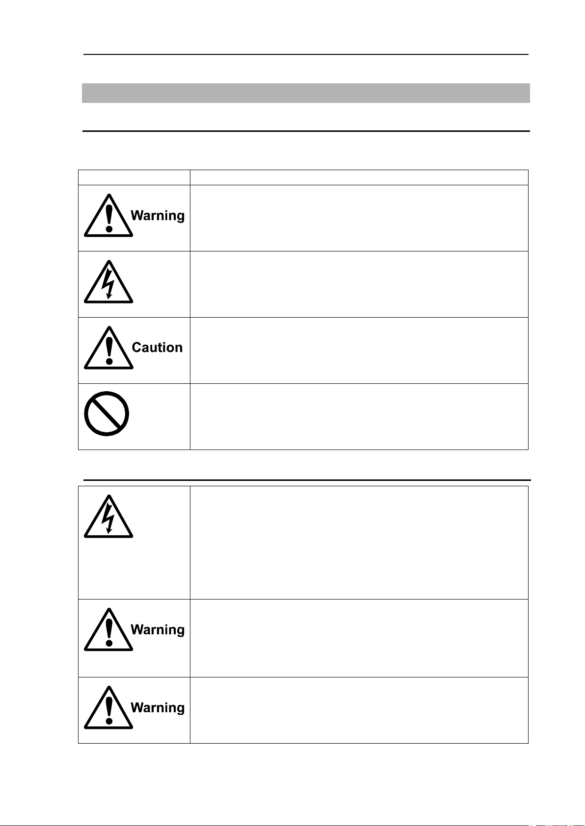
Symbol
Meaning
Mark for warning
This symbol denotes that there is a risk of death or serious injury when not
dealing with it correctly.
Mark for danger high voltage
This symbol denotes that there is a risk of death or serious injury caused by
electric shock when not dealing with it correctly.
Mark for caution
This symbol denotes that there is a risk of slight injury or damage of device
when not dealing with it correctly.
Mark for prohibition
This symbol denotes prohibition of the specified conduct. Description of the
prohibition is displayed near the mark.
Be careful of a high voltage inside.
A high voltage, which may risk your life, is used. This high voltage remains
in the circuit after you have powered off switch. To prevent touching the high
voltage circuit inadvertently, the hard cover is provided to the high voltage
circuit and the high voltage caution label is affixed. Ensure to power off
switch for your safety and discharge the electricity remaining in the capacity
before starting to check. An engineer authorized by our company should
inspect and maintain
Be sure to power off in the boat.
If the power switch is inadvertently powered on during work, you will be
electrified. To prevent such accident from occurring, ensure to power off in
the boat and the power of equipment. Furthermore, it is safer to hang the
caution tag described as [Under Work] near the power switch of equipment.
Be careful of dust
Inhaling dust may cause A respiratory disease. When cleaning the inside of
equipment, be careful not to inhale dust. Wearing a safety mask is
recommended.
For Your Safe Operation
Symbol used in this Operation Manual
The following pictograms are used in this manual. The meaning of each symbols shall be well
understood and the maintenance and inspection shall be carried out.
Caution related to Equipment
0093101202-01 iii
Page 8
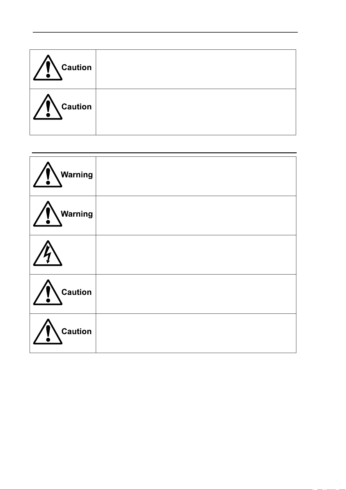
For Your Safe Operation GTD-120
Caution on location of equipment
Do not install the equipment where it is excessively damp and suffers from
excessive water drops.
Escaping from static electricity
The static electricity may be generated from the carpet on the floor in the
cabin or clothes made of synthetic fiber. The static electricity may destroy
the electronic parts on the circuit board. Handle the circuit board, taking the
measure of static electricity free.
Do not disassemble or modify. It may leads to trouble, fire, smoking or
electric shock. In case of trouble, contact our dealer or our company.
In case of smoke or fire, boat power off and the power of this unit. It may
cause fire, electric shock or damage.
Be cautious of remaining high voltage.
A high voltage may remain in the capacitor for several minutes after you
have powered off. Before inspecting inside, wait at least 5 minutes after
powering off or discharge the remaining electricity in an appropriate manner.
Then, start the work.
The information displayed in this unit is not provided directly for your
navigation. For your navigation, be sure to see the specified material.
Use the specified fuse. If un-specified fuse is used, it may cause a fire,
smoke or damage.
Caution related to Handling
iv 0093101202-01
Page 9

GTD-120 Contents
Contents
Important Notice ................................................................................................................................... ii
For Your Safe Operation ...................................................................................................................... iii
Contents ............................................................................................................................................... v
Introduction ......................................................................................................................................... xii
System Configuration ........................................................................................................................ xiii
Configuration of Equipment ............................................................................................................... xiv
Chapter 1 Basic Operation .......................................................................................1-1
1.1 To use keys ........................................................................................................................... 1-1
1.2 How to insert / remove SD card ............................................................................................ 1-2
Insert SD card ............................................................................................................................ 1-2
Remove SD card ........................................................................................................................ 1-2
1.3 Power ON/OFF ..................................................................................................................... 1-3
Power ON ................................................................................................................................... 1-3
Power OFF ................................................................................................................................. 1-3
1.4 Adjust brightness of screen / operation panel ....................................................................... 1-3
Adjust brightness of screen ........................................................................................................ 1-3
Adjust brightness of operation panel .......................................................................................... 1-3
1.5 Select screen ........................................................................................................................ 1-4
Switch display screens ............................................................................................................... 1-5
Register the display screen ........................................................................................................ 1-5
Delete the registered screen ...................................................................................................... 1-5
1.6 Overview of menu operation ................................................................................................. 1-6
Menu operation .......................................................................................................................... 1-6
Entering a numerical value......................................................................................................... 1-8
Entering characters .................................................................................................................... 1-8
1.7 Use [ACTV] key................................................................................................................... 1-10
1.8 Use [HOME] key ................................................................................................................. 1-10
1.9 Use [F1] and [F2] keys ........................................................................................................ 1-10
Register function in [F1] or [F2] keys ....................................................................................... 1-10
[F1] and [F2] keys setting items ................................................................................................1-11
1.10 Marking the POB (Person Over Board) location ................................................................. 1-12
Setting the POB point ............................................................................................................... 1-12
Resetting the POB point ........................................................................................................... 1-12
Canceling the POB ................................................................................................................... 1-13
1.11 Use [INFO] key.................................................................................................................... 1-13
Register function in [INFO] key ................................................................................................ 1-13
Information on objects shown on the chart .............................................................................. 1-13
Detailed information display ..................................................................................................... 1-13
Photograph display .................................................................................................................. 1-14
Tidal information display .......................................................................................................... 1-14
AIS information ......................................................................................................................... 1-15
Numeric screen ........................................................................................................................ 1-15
1.12 Nearest port info ................................................................................................................. 1-16
Chapter 2 Plotter display ..........................................................................................2-1
2.1 Plotter screen ........................................................................................................................ 2-1
0093101202-01 v
Page 10

Contents GTD-120
2.2 Bird view screen .................................................................................................................... 2-1
2.3 2 screen display .................................................................................................................... 2-2
2.4 Operate the cursor ................................................................................................................ 2-2
2.5 Move the chart ....................................................................................................................... 2-3
2.6 Zoom in / out the chart .......................................................................................................... 2-3
Cursor OFF ................................................................................................................................. 2-3
Cursor ON .................................................................................................................................. 2-3
Set the scale for [SCL 1], [SCL 2] and [SCL 3] ........................................................................... 2-3
2.7 Measure the distance and bearing between two points ........................................................ 2-4
CURSOR POS ........................................................................................................................... 2-4
2 POINTS ................................................................................................................................... 2-5
DIST/BRG ................................................................................................................................... 2-6
2.8 Display floating VRM ............................................................................................................. 2-7
Chapter 3 Mark ........................................................................................................ 3-1
3.1 Enter a mark .......................................................................................................................... 3-1
Enter a mark at own ship's position ............................................................................................ 3-1
Enter a mark at the cursor position ............................................................................................ 3-1
3.2 Enter a marked line ............................................................................................................... 3-2
Change mark shape of marked line ........................................................................................... 3-2
Change line style of marked line ................................................................................................ 3-3
3.3 Enter a water temperature / time mark .................................................................................. 3-3
3.4 Event temporary store (EV) ................................................................................................... 3-4
Set mark block to [EV] ................................................................................................................ 3-5
Set the mark points ..................................................................................................................... 3-5
Set how to switch event display ................................................................................................. 3-6
Event temporary store window operation ................................................................................... 3-6
3.5 Change the color of mark ...................................................................................................... 3-7
3.6 Change the size of mark ....................................................................................................... 3-7
3.7 Switching the mark shape set ............................................................................................... 3-7
3.8 Erase mark ............................................................................................................................ 3-8
Erase a mark by cursor .............................................................................................................. 3-8
Erase a mark by selecting a mark color and a shape ................................................................ 3-9
Erase a mark by selecting a mark list ...................................................................................... 3-10
3.9 Change a start block for recording a mark .......................................................................... 3-11
3.10 Edit entered marks .............................................................................................................. 3-12
Change mark display settings .................................................................................................. 3-12
Change the color, shape, position, etc. of the input mark ........................................................ 3-13
Transfer the input mark to another block etc. ........................................................................... 3-14
Chapter 4 Track ....................................................................................................... 4-1
4.1 Record own ship’s track ON / OFF ....................................................................................... 4-1
4.2 Record other ship’s track ....................................................................................................... 4-2
4.3 Set track indication while track record is interrupted ............................................................. 4-3
4.4 Change the color of track ...................................................................................................... 4-4
Change the color of own ship’s track ......................................................................................... 4-4
Change the color of own ship’s track with water temperature range ......................................... 4-4
Change the color of own ship's track with water temperature width .......................................... 4-5
vi 0093101202-01
Page 11

GTD-120 Contents
Change the color of own ship's track with water depth range ................................................... 4-6
4.5 Change the type of own ship’s track line .............................................................................. 4-7
4.6 Setting the number of recording points and recording interval of own ship's track .............. 4-7
Set the number of record points of own ship's track .................................................................. 4-8
Set recording interval of own ship's track .................................................................................. 4-8
4.7 Save recorded track .............................................................................................................. 4-9
4.8 Display ON / OFF the saved track on the screen ................................................................. 4-9
4.9 Erase track .......................................................................................................................... 4-10
Erase the track by selecting a color ......................................................................................... 4-10
Erase the track by selecting an area ........................................................................................ 4-10
Erase the track automatically at power on start ....................................................................... 4-12
4.10 GPS buoy ............................................................................................................................ 4-13
Enable GPS buoy function ....................................................................................................... 4-14
Display ON / OFF GPS buoy number and water temperature ................................................. 4-14
Change the color of GPS buoy ................................................................................................ 4-15
View received data from GPS buoy ......................................................................................... 4-15
Monitor received data from GPS buoy ..................................................................................... 4-16
Delete GPS buoy data ............................................................................................................. 4-17
Chapter 5 Waypoint Navigation ................................................................................5-1
5.1 Setting the input mark to the waypoint .................................................................................. 5-1
Specify a mark with the cursor ................................................................................................... 5-1
Specify a mark number .............................................................................................................. 5-2
5.2 Enter the latitude and longitude and set the destination ....................................................... 5-2
5.3 Setting the cursor position as the destination ....................................................................... 5-3
5.4 Setting the waypoint from the waypoint history .................................................................... 5-3
5.5 Setting own port as the waypoint .......................................................................................... 5-4
5.6 Displaying ON / OFF the course line .................................................................................... 5-4
5.7 Setting the ship speed for calculating the TTG ..................................................................... 5-4
5.8 Resetting the origin of the course line .................................................................................. 5-5
5.9 Cancel waypoint navigation .................................................................................................. 5-5
Chapter 6 Route Navigation .....................................................................................6-1
6.1 Creating routes...................................................................................................................... 6-1
Create a route with a cursor ....................................................................................................... 6-1
Create a route by input the latitude and longitude ..................................................................... 6-2
6.2 Execute route navigation ...................................................................................................... 6-3
Select with cursor and execute .................................................................................................. 6-4
Select from the list and execute ................................................................................................. 6-6
6.3 Changing the waypoint switching during route navigation .................................................... 6-7
6.4 Resetting the starting point during route navigation ............................................................. 6-8
6.5 Canceling route navigation ................................................................................................... 6-8
6.6 Move the waypoint during route navigation .......................................................................... 6-8
6.7 Setting the switching method of the waypoint ..................................................................... 6-10
PERP ....................................................................................................................................... 6-10
CI ....................................................................................................................................... 6-10
BISECTOR ............................................................................................................................... 6-10
MAN ....................................................................................................................................... 6-10
0093101202-01 vii
Page 12

Contents GTD-120
6.8 Setting the route navigation mode ...................................................................................... 6-11
Active ....................................................................................................................................... 6-11
Fix ....................................................................................................................................... 6-12
6.9 Delete the route ................................................................................................................... 6-13
Select with the cursor to delete the route ................................................................................. 6-13
Select from the list to delete the route ...................................................................................... 6-14
6.10 Move the waypoint of the created route .............................................................................. 6-15
Use the cursor to move the waypoint ....................................................................................... 6-15
Enter the latitude and longitude to move the waypoint ............................................................ 6-16
6.11 Add the waypoint to the created route ................................................................................ 6-17
Use the cursor to add the waypoint .......................................................................................... 6-17
Enter the latitude and longitude to add the waypoint ............................................................... 6-18
6.12 Delete the waypoint of the created route ............................................................................ 6-19
Use the cursor to delete the waypoint ...................................................................................... 6-19
Enter the waypoint number to delete the waypopint ................................................................ 6-20
6.13 Edit comments ..................................................................................................................... 6-22
Chapter 7 Drawing ................................................................................................... 7-1
7.1 Creating drawings ................................................................................................................. 7-1
Create a drawing with a cursor ................................................................................................... 7-1
Create a drawing by entering the latitude and longitude ............................................................ 7-2
Create a drawing by using the [DRAW] key ............................................................................... 7-4
7.2 Delete the drawing ................................................................................................................ 7-6
Select with the cursor to delete the drawing .............................................................................. 7-6
Select from the list to delete the drawing ................................................................................... 7-7
7.3 Display the drawing or change the width of the drawing line ................................................ 7-7
7.4 Move the point of created drawings ...................................................................................... 7-8
Use the cursor to move the point ............................................................................................... 7-8
Enter the latitude and longitude to move the point ..................................................................... 7-9
7.5 Add the point to the created drawing .................................................................................. 7-11
Use the cursor to add the point ................................................................................................ 7-11
Enter the latitude and longitude to add a point ......................................................................... 7-12
7.6 Delete the point of the created drawing .............................................................................. 7-13
Use the cursor to delete the point ............................................................................................ 7-13
Enter the point number to delete the point ............................................................................... 7-14
7.7 Edit comments ..................................................................................................................... 7-15
Enter comments for each drawing block .................................................................................. 7-15
Enter comments on created drawings ...................................................................................... 7-16
7.8 Parallel drawing ................................................................................................................... 7-17
Register the parallel drawing in the [DRAW] key ..................................................................... 7-18
Display ON / OFF parallel drawing ........................................................................................... 7-18
Setting the drawing method for parallel drawing ...................................................................... 7-19
Fine adjustment the parallel drawing ........................................................................................ 7-24
7.9 Diamond drawing ................................................................................................................ 7-25
Register the diamond drawing in the [DRAW] key ................................................................... 7-26
Display ON / OFF diamond drawing ........................................................................................ 7-26
Setting the drawing method for diamond drawing .................................................................... 7-27
viii 0093101202-01
Page 13

GTD-120 Contents
Fine adjustment the diamond drawing ..................................................................................... 7-31
Chapter 8 Alarm .......................................................................................................8-1
8.1 Displaying / not displaying the alarm zone ........................................................................... 8-1
8.2 Setting arrival alarm .............................................................................................................. 8-2
8.3 Setting POB alarm ................................................................................................................ 8-2
8.4 Setting XTE alarm ................................................................................................................. 8-3
8.5 Setting CPA/TCPA alarm ....................................................................................................... 8-3
8.6 Setting speed alarm .............................................................................................................. 8-4
8.7 Setting area alarm ................................................................................................................. 8-5
Set the function of area alarm .................................................................................................... 8-5
Set the area alarm range ........................................................................................................... 8-6
8.8 Setting drawing alarm ........................................................................................................... 8-7
Set drawing alarm function......................................................................................................... 8-7
Set the drawing alarm range ...................................................................................................... 8-8
8.9 Setting depth limit alarm ....................................................................................................... 8-8
Set the function of depth limit alarm ........................................................................................... 8-8
8.10 Setting grounding alarm ........................................................................................................ 8-9
Chapter 9 AIS ...........................................................................................................9-1
9.1 Enable the AIS display function ............................................................................................ 9-1
9.2 Setting the detection range ................................................................................................... 9-2
9.3 Display ON / OFF Class B AIS targets .................................................................................. 9-2
9.4 Setting minimum detection speed ......................................................................................... 9-3
9.5 Setting minimum hull length .................................................................................................. 9-3
9.6 Display ON / OFF ship name ................................................................................................ 9-4
9.7 Display ON / OFF vector lines .............................................................................................. 9-4
9.8 Change the shape of the stop symbol .................................................................................. 9-5
Chapter 10 GPS/DGPS .......................................................................................... 10-1
10.1 GPS / DGPS monitor screen .............................................................................................. 10-1
10.2 GPS / DGPS settings .......................................................................................................... 10-2
Chapter 11 Setup I/O Interface ............................................................................... 11-1
11.1 Set the baudrate (transmission speed) ................................................................................ 11-1
11.2 Set the input sentence ......................................................................................................... 11-1
11.3 Set output sentence ............................................................................................................. 11-2
11.4 Monitoring input sentences .................................................................................................. 11-3
Chapter 12 Save to SD card and import from SD card to Display unit ................... 12-1
12.1 Initialize the SD card ........................................................................................................... 12-1
12.2 Save data to SD card .......................................................................................................... 12-3
12.3 Save the data of the SD card to the internal memory ......................................................... 12-6
12.4 Erase data in the SD card ................................................................................................... 12-9
12.5 Backup ............................................................................................................................... 12-11
12.6 Restore .............................................................................................................................. 12-12
Chapter 13 Menu Operation ................................................................................... 13-1
13.1 Chart data menu ................................................................................................................. 13-1
Chart for each menu item ......................................................................................................... 13-1
Marine ...................................................................................................................................... 13-2
0093101202-01 ix
Page 14

Contents GTD-120
Land ....................................................................................................................................... 13-3
Depth ....................................................................................................................................... 13-4
13.2 Display menu ....................................................................................................................... 13-5
Screen display 1 ....................................................................................................................... 13-5
Screen display 2 ....................................................................................................................... 13-8
Set position indication ............................................................................................................ 13-11
Set additional information display........................................................................................... 13-14
Display water temperature / water depth graph ..................................................................... 13-21
13.3 SYS/ALM menu ................................................................................................................. 13-23
System 1 ................................................................................................................................. 13-23
System 2 ................................................................................................................................. 13-25
System 3 ................................................................................................................................. 13-27
Chapter 14 Maintenance........................................................................................ 14-1
14.1 Simulation ............................................................................................................................ 14-1
14.2 System test .......................................................................................................................... 14-2
14.3 Color palette ........................................................................................................................ 14-5
14.4 Screen shot ......................................................................................................................... 14-8
Execute screen shot ................................................................................................................. 14-8
Display of stored pictures ......................................................................................................... 14-8
Erase stored pictures ............................................................................................................... 14-9
14.5 Memory erase ................................................................................................................... 14-10
Erase mark ............................................................................................................................. 14-10
Erase track ............................................................................................................................. 14-10
Erase drawing......................................................................................................................... 14-11
Erase TGT track ..................................................................................................................... 14-12
Erase route ............................................................................................................................. 14-12
Erase picture .......................................................................................................................... 14-13
14.6 Regist own port ................................................................................................................. 14-13
Chapter 15 Inspection ............................................................................................ 15-1
15.1 Inspection ............................................................................................................................ 15-1
15.2 Cleaning .............................................................................................................................. 15-1
15.3 Fuse Replacement .............................................................................................................. 15-2
15.4 If you suspect a trouble ....................................................................................................... 15-2
Chapter 16 Installation ........................................................................................... 16-1
16.1 Items of Caution on Installation ........................................................................................... 16-1
Unpacking the components ...................................................................................................... 16-1
Inspection of components and accessories ............................................................................. 16-1
Decision of Installing Location .................................................................................................. 16-1
Laying and Connection of Cable .............................................................................................. 16-2
Confirmation after Installation ................................................................................................... 16-2
16.2 Display unit installation ........................................................................................................ 16-3
Table mounting ......................................................................................................................... 16-3
Flush mounting ......................................................................................................................... 16-5
16.3 Cable connection ................................................................................................................. 16-6
Cable connection to Display unit .............................................................................................. 16-6
Connector pin assignment ........................................................................................................ 16-7
x 0093101202-01
Page 15

GTD-120 Contents
DC power cable connection (CW-259-2M) .............................................................................. 16-8
Connection the GPS sensor .................................................................................................... 16-8
Connection with navigation equipment (J1, J2, J3, J4) ........................................................... 16-9
Connection with AIS receiver (J6) (Prepared by a customer) .................................................. 16-9
Connection of external buzzer and external monitor (J8) (Prepared by a customer) ............ 16-10
Connection of remote controller (RCW-15) (J9) (Option) ...................................................... 16-10
Data transfer from GTD-110 / 150 .......................................................................................... 16-10
Chapter 17 Input / Output sentence list .................................................................. 17-1
17.1 Input sentence .................................................................................................................... 17-1
17.2 Output sentence .................................................................................................................. 17-2
Chapter 18 Appendix .............................................................................................. 18-1
18.1 Menu tree ............................................................................................................................ 18-1
18.2 Specifications .................................................................................................................... 18-10
18.3 External view and dimensions ........................................................................................... 18-11
Index .................................................................................................................. 1
0093101202-01 xi
Page 16

Introduction GTD-120
Introduction
GTD-120 is a high-performance GPS plotter with many useful functions.
Main features of GTD-120 are as follows.
Dual range map, ability to display two different ranges on one screen.
Available Bird view display.
Equipped with AIS display function*. Up to 128 target symbols can be displayed.
(*In order to use the AIS display function, it is necessary to connect with the AIS receiver is
necessary.)
High performance LCD ensures high visibility under all conditions.
Adoption of special filter (AR coat).
The image is clearly displayed in sunlight, and reflection on the LCD screen is also prevented.
Supports SD card sizes between 2 and 8GB.
Easy flush mount installation from the front.
With standard equipment for analog RGB output. The plotter images can be displayed on an
external monitor, so you can check it even in a place away from the Display unit. (External monitor
will be arranged by customer.)
xii 0093101202-01
Page 17
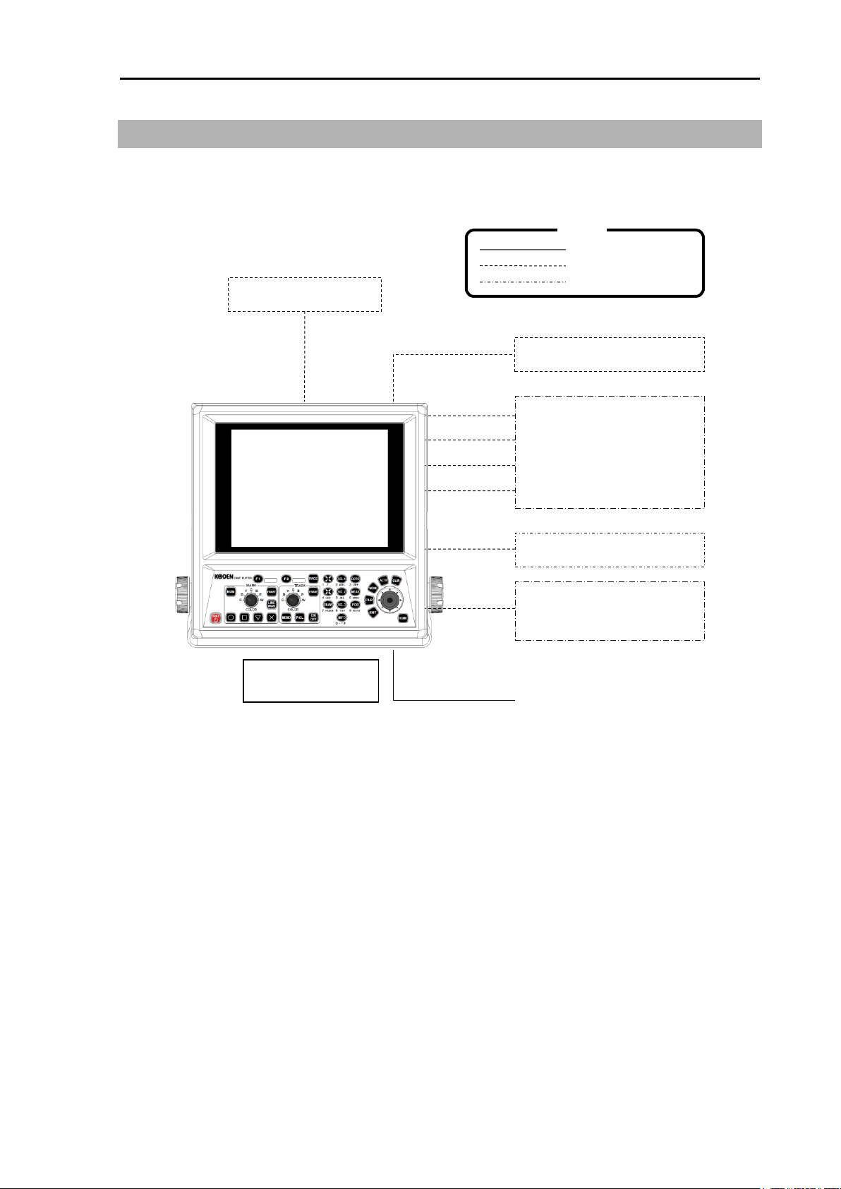
GTD-120 System Configuration
Display unit
GTD-120
GPS sensor
J5
Navigation equipment
Echo sounder
Radar
Autopilot
Sonar
J1
J2
J3
J4
AIS
J6
External monitor (VGA)
External buzzer
J8
POWER
10.8 to 31.2VDC
Standard
Option
Owner supplied
Remote controller
Legend
System Configuration
Connection diagram
0093101202-01 xiii
Page 18
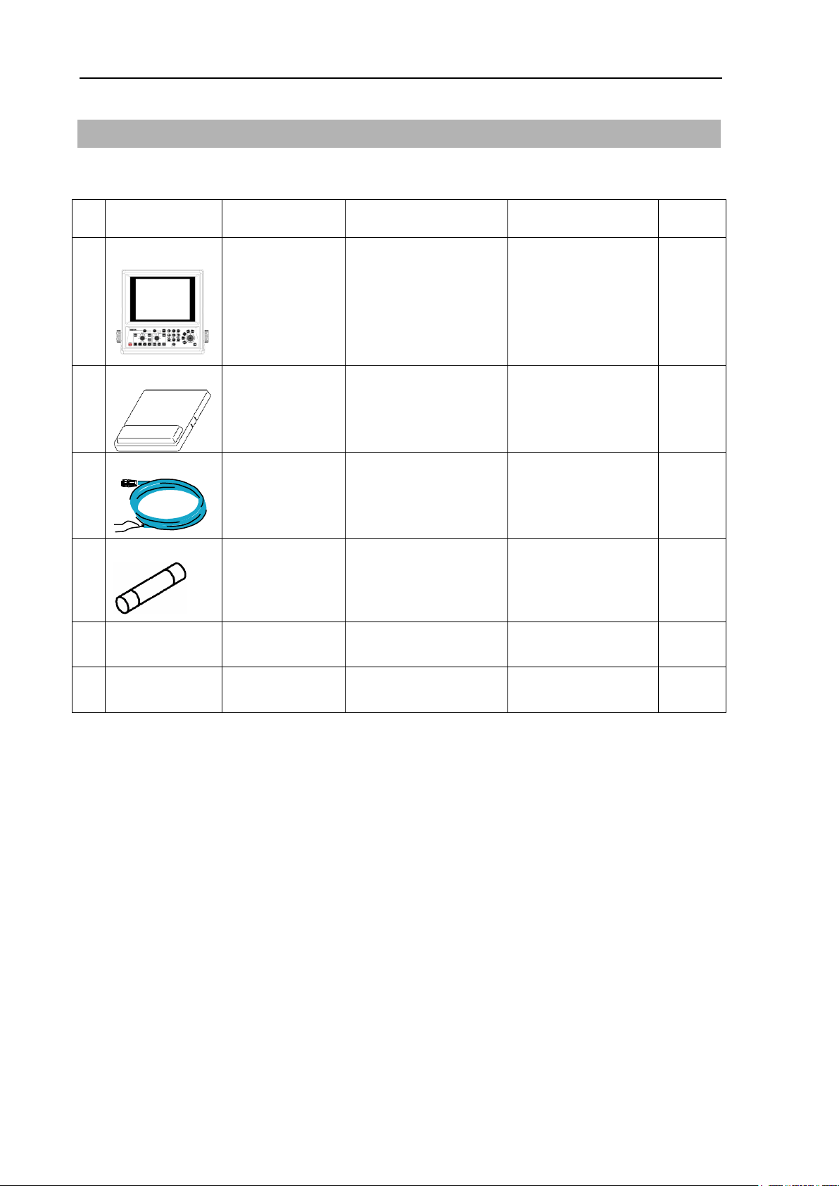
Configuration of Equipment GTD-120
No
Name of item
Type
Remarks
Weight/
Length
Quantity
1
Display unit
GTD-120
With mounting
bracket and knobs
8.0 kg
1
2
Hard cover
A30MB10250
390g
1 3 DC power cable
CW-259-2M
With 3-pin water
resistant connector
and one end plain
2m
1
4
Fuse
F-7161-5A
Cylinder (φ6.4 x
30)
Normal fusion type for
main power
1
5
Operation
Manual
GTD-120.OM.E
English
1 6
Quick
Reference
GTD-120.QR.E
English
1
Configuration of Equipment
Standard equipment configuration list
xiv 0093101202-01
Page 19
GTD-120 Configuration of Equipment
No
Item Name
Type
Remarks
Weight/
Length
1
GPS sensor
GPS-20A-10M-B
[KODEN]
For GPS position fixing with
power & signal cable connector
0.6kg/10m
2
GPS compass
KGC-222
With Display unit and GPS
Antenna
3
Remote controller
RCW-15
With 5m cable, (Assembled the
connection cable into the
Operation unit)
4
SD card
KDN-SDM4GMC
4GB
5
GPS antenna holder
RAH- 29
Ratchet mount
6
Connecting cable
CW-373-5M
6 pin waterproof connectors both
ends
5m
7
CW-376-5M
Fly leads /
6 pin waterproof connector
5m 8 CW-387-5M
Fly leads /
8 pin waterproof connector
5m
9
CW-576-0.5M
With a 10-pin water resistant
connector and D-Sub
connector (analog RGB) +
Alarm out
0.5m
10
CW-420-5M
7 pin waterproof connectors both
ends
5m
11
Power rectifier
PS-010
With 2 pieces of 5A fuse
12
AC power cable
VV-2D8-3M
Both ends plain
3m
13
Connector
BD-06BFFA- LL6001
6 pin waterproof connector
14
BD-07BFFA- LL6001
7 pin waterproof connector
15
BD-08BFFA- LL6001
8 pin waterproof connector
16
Operation Manual
GTD-120.OM.E
English
17
Quick Reference
GTD-120.QR.E
English
Optional List
0093101202-01 xv
Page 20

- This page intentionally left blank.-
Page 21
GTD-120 Chapter1 Basic Operation
1 2 3 4 5 6 7 8 9
10
11
12
13
14
15
16
17
18
19
20
21
22
23
26
27
28
24
Cancel WPT navigation
Cancel RTE navigation
Cancel POB navigation
Stop alarm sound
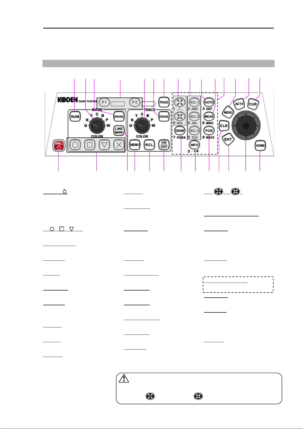
CAUTION: The [ ↑ ] [ ↓ ] [←] [→] notation in this manual
indicates the direction of knocking down the joystick.
: [Zoom in] : [Zoom out]
25
Chapter 1 Basic Operation
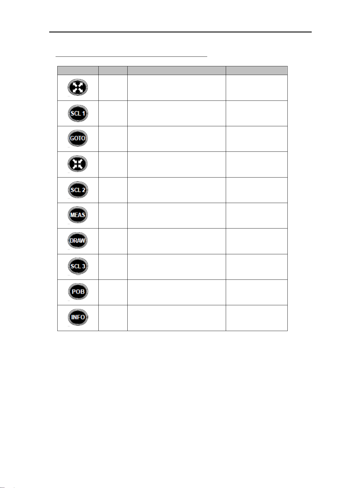
1.1 To use keys
1. [BRILL ]
Press: Power ON
Adjust brightness of
screen/operation panel
Long press: Power OFF
2. [ ], [ ], [ ], [X]
Enter a mark
3. [LINE MARK]
Enter a marked line
4. [MEMO]
Save recorded track
5. [RCL]
Saved track Display ON / OFF
6. [ON/OFF]
Recoad track ON/OFF
7. [DRAW]
Create drawing, parallel line
drawing, diamond line drawing
8. [INFO]
Display map information etc.
9. [POB]
Setting POB
10. [CLR]
11. [ENT]
Confirm setting value etc.
12. [Joystick]
Move chart / cursor
Select menu item
13. [HOME]
Menu screen OFF
Cursor OFF
Return own ship to the center.
14. [NUM]
Enter mark by numeric input
15. [MARK] knob
Change mark color
16. [ERASE]
Erase mark
17. [F1], [F2]
Call up the registered function
18. [TRACK] knob
Change track color
19. [ERASE]
Erase track
20. [PAGE]
Switch display screen
21. [ ], [ ]
Chart zoom In / Out
Scroll the list
22. [SCL1], [SCL2], [SCL3]
One touch scale adjustment
23. [GOTO]
Set a WPT
Reset a WPT
Skip a WPT on the route
24. [MEAS]
Measure a distance and a
direction between two points
25. [Numeric keypad]
Enter numbers and characters
26. [MENU]
Menu screen ON / OFF
27. [ACTV]
Select active screen on
split screen display
Select menu item
28. [CUR]
Cursor Display ON / OFF
0093101202-01 1-1
Page 22
Chapter1 Basic Operation GTD-120
After removing the SD card, please close the cover securely. If cover is
not closed properly water and dust may enter and cause malfunctions.
CAUTION:
Some SD cards may not work in the unit.
CAUTION:
Please only use SD card sizes between 2 and 8GB.
CAUTION:
1.2 How to insert / remove SD card
GTD-120 can display C-MAP chart of SD card. C-MAP chart card is owner supplied.
In addition, store data such as marks and track by using a commercially available SD card.
When using the SD card for the first time, be sure to initialize it with this unit. For the procedure to
initialize, refer to "Chapter 12 Save to SD card and import from SD card to Display unit, 12.1
Initialize the SD card".
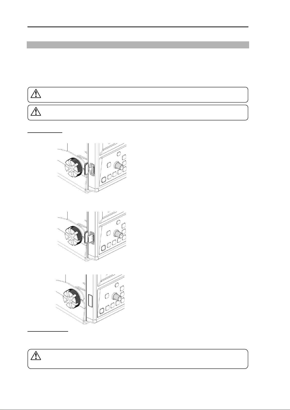
Insert SD card
1. Open the cover of the SD card slot.
2. Insert the SD card.
Be careful with the orientation of the SD card and insert until slight click is heard.
3. Close the cover securely for waterproofing.
Remove SD card
Open the cover of the SD card slot. Push the SD card once and gently release the finger, the SD
card will eject and can be removed.
1-2 0093101202-01
Page 23
GTD-120 Chapter1 Basic Operation
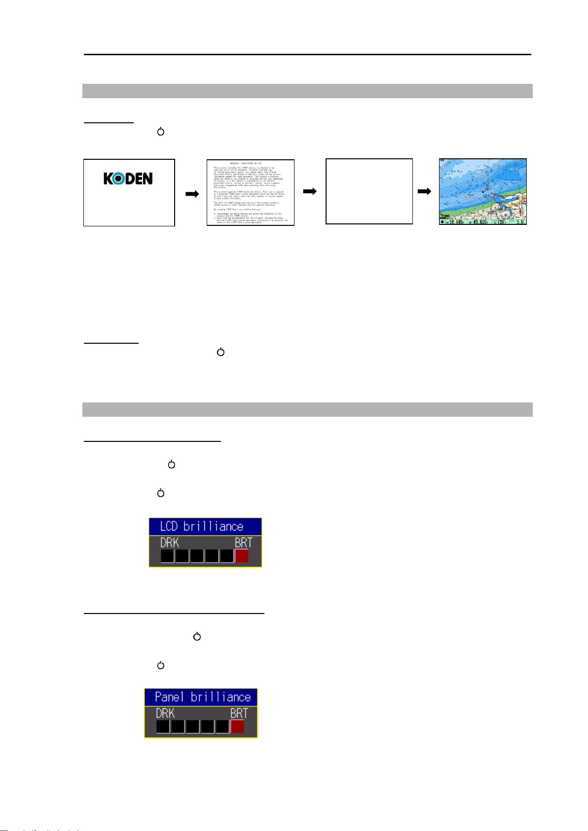
Initial screen
Warning screen
Normal screen
GTD-120
Now Loading
Data loading screen
1.3 Power ON/OFF
Power ON
1. Press [BRILL ] key.
After power on, the screen switches in the following order.
2. While the "Warning screen" is displayed, press [ENT] key. (After “By pressing <ENT key>”
display by red character)
The “Data loading” screen is displayed.
The “Normal screen” is displayed and the plotter system can be used.
Power OFF
1. Press and hold the [BRILL ] key for 3 seconds or longer.
After power off, please install a hard cover to protect the LCD screen.
1.4 Adjust brightness of screen / operation panel
Adjust brightness of screen
Adjust screen brightness for better visibility.
E ach time [BRILL ] key is pressed, [LCD brilliance] and [PANEL brilliance] will be selected.
1. Press [BRILL ] key. The [LCD brilliance] window is displayed.
2. Use joystick [←] [→] to adjust the screen brightness.
3. Press [Menu] to close the [LCD brilliance] window.
Adjust brightness of operation panel
Adjust the brightness of the operation panel.
Each time press [BRILL ] key, [LCD brilliance] and [PANEL brilliance] changes.
1. Press [BRILL ] key briefly. The [PANEL brilliance] window is displayed.
2. Use joystick [←] [→] to adjust the operation panel brightness.
3. Press [Menu] key to close the [PANEL brilliance] window.
0093101202-01 1-3
Page 24
Chapter1 Basic Operation GTD-120
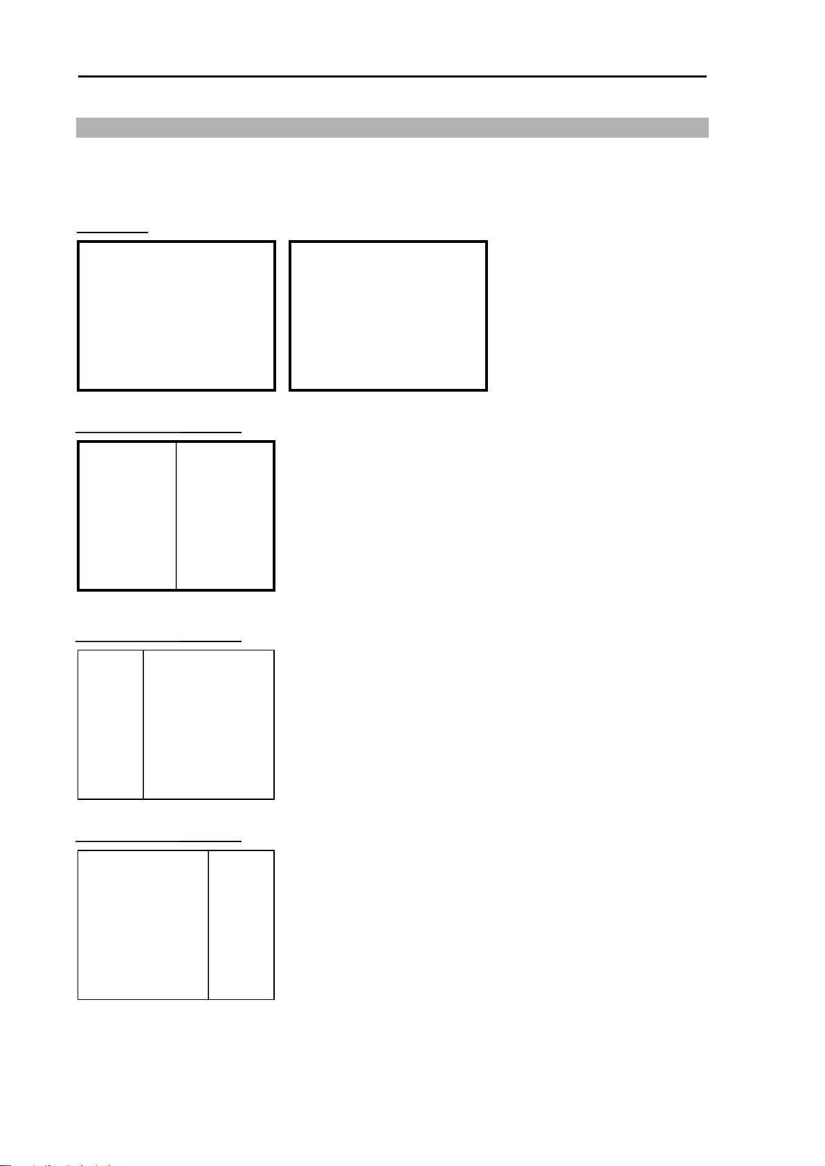
Plotter screen
Bird view screen
Plotter
screen
●Full screen
●2 screen display (Split 1:1)
●2 screen display (Split 1:2)
●2 screen display (Split 2:1)
Plotter screen
Plotter screen
Plotter screen
Plotter screen
Plotter
screen
1.5 Select screen
There are 5 different displays that can be selected. Each time [PAGE] key is pressed, different
display will be brought up.
By factory default 3 displays are setup which are outlined below with a thicker line.
1-4 0093101202-01
Page 25
GTD-120 Chapter1 Basic Operation
Plotter screen Plotter screen
Plotter screen
Bird view screen
(1)
(2)
(3)
The switching order by pressing
[PAGE] of the display screen is
as follows.
(1)→(2)→(3)→(1)→(2)→(3)→・・・
Switch display screens
1. Each time [PAGE] key is pressed, the screen changes.
(The figure below shows how to change the display screen when shipped from the factory.)
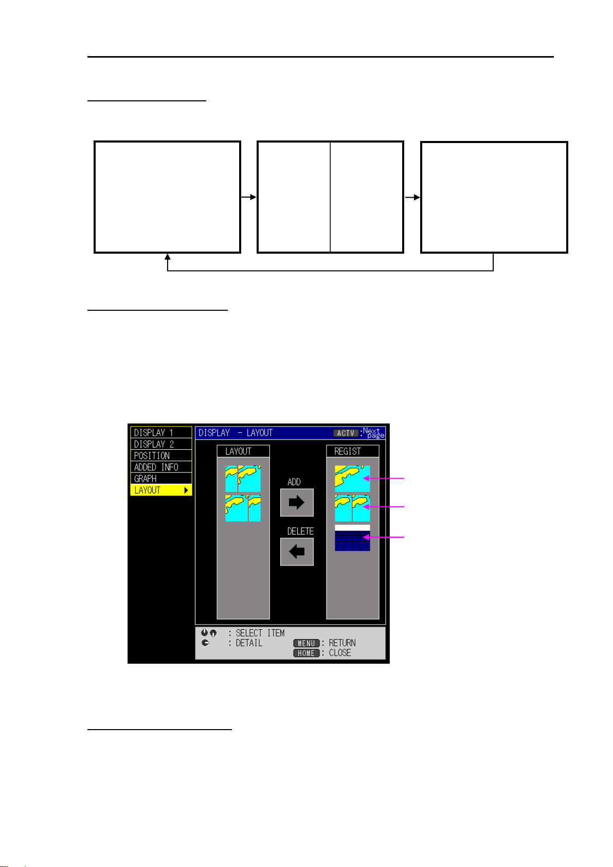
Register the display screen
You can edit registration of the display modes to different ones.
1. Press [MENU] key to display the menu screen.
Use joystick [ ↑ ] [ ↓ ] to select [DISPLAY], and use joystick [→].
Use joystick [ ↑ ] [ ↓ ] to select [LAYOUT], and use joystick [→].
2. Use joystick [ ↑ ] [ ↓ ] to select the screen to be registered from [LAYOUT].
Use joystick [→], and move the cursor to [ADD].
3. Press [ENT] key, add the screen selected in [LAYOUT].
4. To register more screens, repeat steps 2 and 3.
5. Press [MENU] key several times to close the menu.
Delete the registered screen
1. Press [MENU] key to display the menu screen.
Use joystick [ ↑ ] [ ↓ ] to select [DISPLAY], and use joystick [→].
Use joystick [ ↑ ] [ ↓ ] to select [LAYOUT], and use joystick [→].
0093101202-01 1-5
Page 26
Chapter1 Basic Operation GTD-120
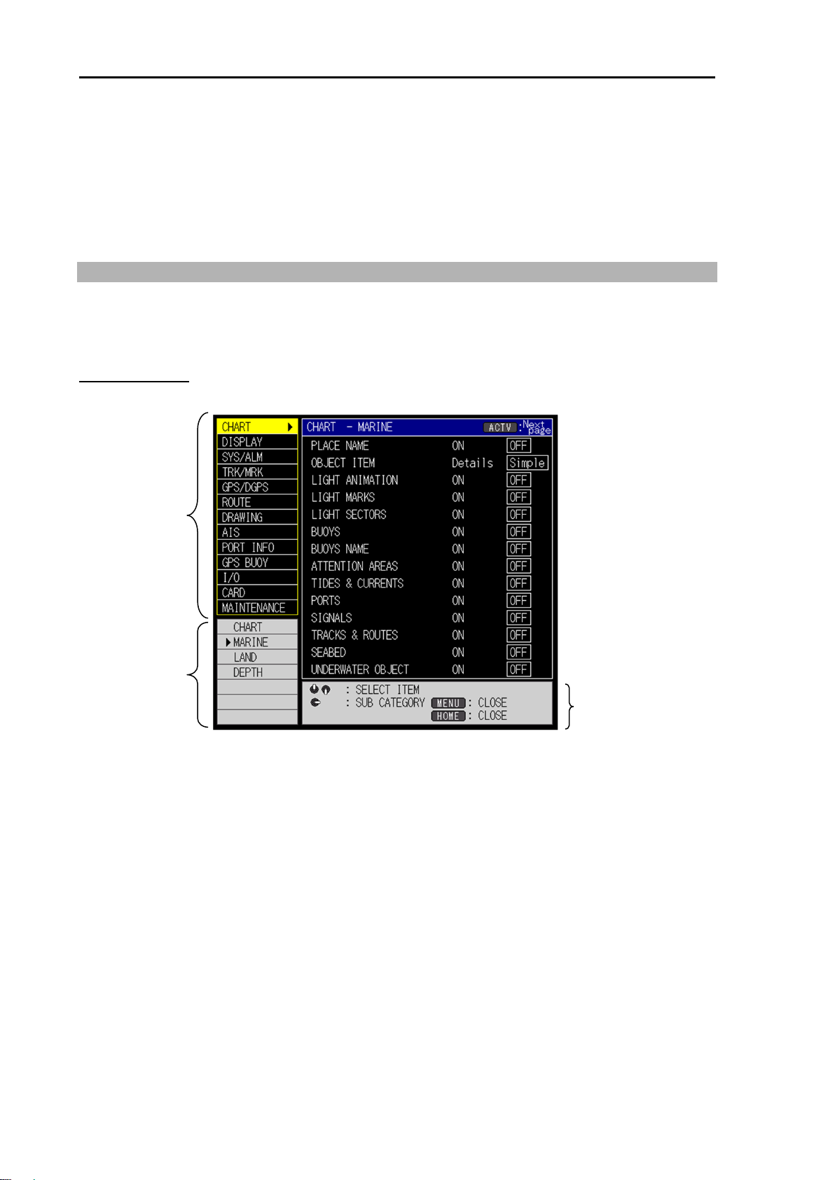
Main item
Sub item
Operation guide
2. Use joystick [ ↑ ] [ ↓ ] to select the screen to be deleted from [REGIST].
Use joystick [←], and move the cursor to [DELETE].
3. Press [ENT] key, delete the screen selected in [LAYOUT].
4. To delete more screens, repeat steps 2 and 3.
5. Press [MENU] key several times to close the menu.
1.6 Overview of menu operation
To change various settings etc., open the menu.
Here, the basic menu operation procedure is shown, but there are many menus with special
operations. In that case, please follow the operation guide displayed on the screen.
Menu operation
1. Press [MENU] key to display the menu screen.
2. Use joystick [ ↑ ] [ ↓ ] to select main item, and use joystick [→].
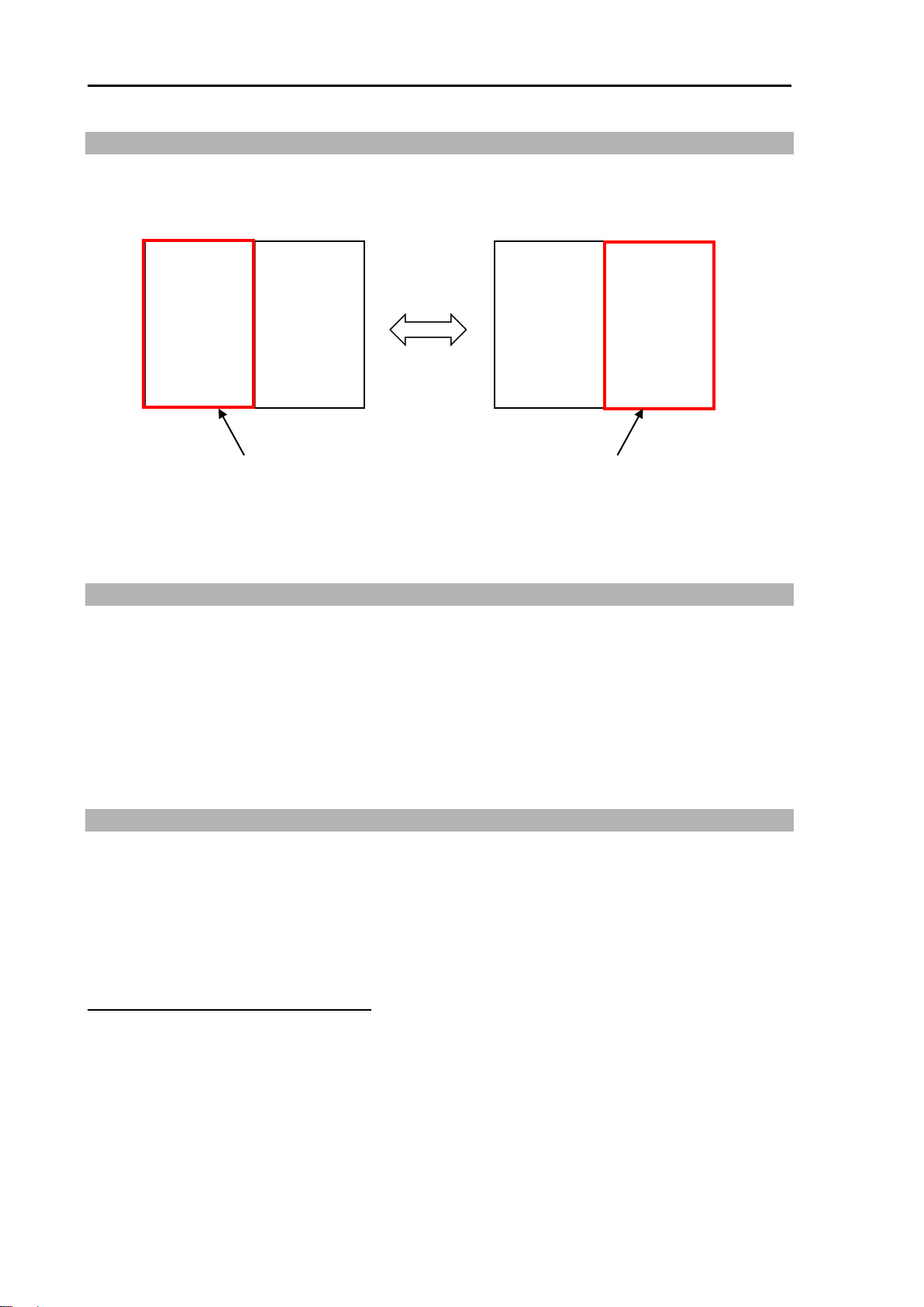
*While selecting the main item, switch sub items by pressing [ACTV] key.
1-6 0093101202-01
Page 27
GTD-120 Chapter1 Basic Operation
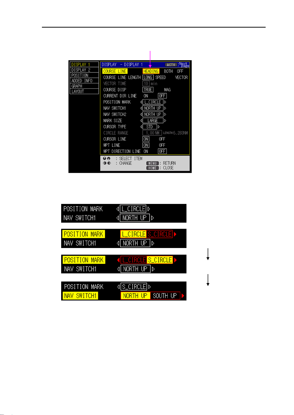
Selection cursor (red frame)
In case, no selection cursor (red frame)
[ ↑ ], [ ↓ ] to select [POSITION MARK]
[→]
[ ↓ ]
3. Use joystick [ ↑ ] [ ↓ ] to select sub item.
4. Use joystick [←] [→] and select the setting value with the selection cursor (red frame).
If the setting value is 4 or more items, the following operations are performed.
5. Press [MENU] key several times to close the menu.
*Close the menu with one touch by pressing [HOME] key.
0093101202-01 1-7
Page 28
Chapter1 Basic Operation GTD-120
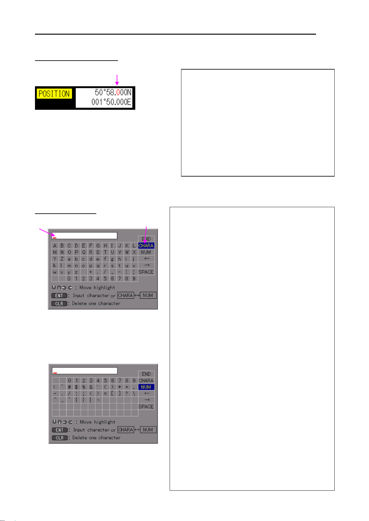
Alphabet input screen
Numeric and symbol input screen
Character input cursor
Character selection cursor
(1) Select the character format to enter.
Move the character selection cursor, select [CHARA]
and press [ENT] key to enter [Alphabet input
screen].
Move the character selection cursor, select [NUM]
and press [ENT] key to enter [Numeric and symbol
input screen].
*The same operation can be done by pressing
[ACTV] key.
(2) Move the character selection cursor and select the
first character.
*Also possible to enter with the numeric keypad.
(3) Press [ENT] key.
*If mistake is made in entering characters, select [←]
with the character selection cursor and press [ENT]
key to return to that character and select the correct
character again.
Select [←] with the character selection cursor and
press [ENT] key to move the character input cursor
to the left.
Select [→] with the character selection cursor and
press [ENT] key to move the character input cursor
to the right.
To enter spaces, select [SPACE] with
the character selection cursor
and press [ENT] key.
(4) Repeat the procedure (1) to (3) and enter characters.
(5) Finally, select [END] with the character selection
cursor, and press [ENT] key.
*The same operation can be done by pressing
[MEMO] key.
The selected number turns red.
1) Use joystick [←] [→], specify the digit from which
the numerical value is to be changed.
(2) Use joystick [ ↑ ] [ ↓ ] to change the value.
[ ↑ ]: The numeric value increases.
[ ↓ ]: The numeric value decreases.
*Also possible to enter with the numeric keypad.
After entering the numerical value, move to
the digit by using joystick [←] [→].
(3) Press [MENU] key to end input.
Entering a numerical value
*To enter the latitude and longitude continuously,
press [OFF/ON] key and specify the digit to the
start positon for entering. The background color
of the enter start digit changes.
.
Also switch between north latitude (N) <=> south latitude (S),
east longitude (E) <=> west longitude (W) by pressing [PAGE] key.
Entering characters
1-8 0093101202-01
Page 29
GTD-120 Chapter1 Basic Operation
Key
Numeric
Alphabet
Symbol
1
. / _ - : ;
2
A B C a b c
3
D E F d e f
4
G H I g h i
5
J K L j k l
6
M N O m n o
7
P Q R S p q r s
8
T U V t u v
9
W X Y Z w x y z
0
- + #
List of assignment of each key when entering characters
0093101202-01 1-9
Page 30
Chapter1 Basic Operation GTD-120
Plotter screen Plotter screen
Plotter screen Plotter screen
[ACTV]
Red border screen is valid
Red border screen is valid
1.7 Use [ACTV] key
On the 2 screen display, press the [ACTV] key, and the effective screen changes.
The screen with the red frame is effective screen, so you can change the scale, operate the cursor,
etc. in the effective screen.
*In addition to switching the effective screen, perform operations such as sub item switching by
menu operation.
1.8 Use [HOME] key
Press [HOME] key, for example, when own ship has disappeared from the screen (return to own
ship from outside the screen) or close the menu screen.
Press [HOME] key, the following operation is performed.
• When the menu screen and various windows are displayed, close them all.
• When the cursor is displayed, hide the cursor.
• Return own ship's position to the center of the screen.
1.9 Use [F1] and [F2] keys
[F1] and [F2] keys are to call registered functions with one touch. By simply pressing this key, call
up the registered function, enabling quick operation.
1. Press [F1] (or [F2]) key.
The setting items are displayed on the screen.
2. Change the setting by using joystick [ ↑ ] [ ↓ ] [←] [→] as necessary.
Register function in [F1] or [F2] keys
At factory default value, [Nav switch] is registered in [F1] key, [Screen shot] is registered in [F2]
key.
1. Press [MENU] key to display the menu screen.
Use joystick [ ↑ ] [ ↓ ] to select [SYS/ALM], and use joystick [→].
Use joystick [ ↑ ] [ ↓ ] to select [SYSTEM1], and use joystick [→].
2. Use joystick [ ↑ ] [ ↓ ] to select [F1 KEY] (or [F2 KEY]).
3. Use joystick [←] [→] to select the function to be registered.
1-10 0093101202-01
Page 31

GTD-120 Chapter1 Basic Operation
Item
Function content
Stabilization
Set the speed display stability.
1: Response is slow
2: Response is between 1 and 3
3: Response is fast
*When moving at low speed, setting "1" may improve
the stability of the speed.
Nav switch
Sets the direction of the upward screen.
NORTH UP: Always keeps displaying true north on the top of the screen.
SOUTH UP: Always keeps displaying true sourth on the top of the screen.
EAST UP: Always keeps displaying true east on the top of the screen.
WEST UP: Always keeps displaying true west on the top of the screen.
COURSE UP*: Always keeps displaying a waypoint positoin on the top of
the screen.
*Except WPT navigation and RTE navigation, Always keeps displaying
true north on the top of the screen.
HEAD UP: Always keeps displaying a heading line on the top of the
screen and own ship is fixed in the center of the screen while the map
moves according to own ship’s movement.
VRM
This mode is used when measuring a distance from own ship.
ON: Variable Measuring Marker display ON.
OFF: Variable Measuring Marker display OFF.
Screen shot
Memorize a current displayed image. (Max:100)
Map color
Change the arrangement of color in the map.
4. Press [MENU] key several times to close the menu.
[F1] and [F2] keys setting items
0093101202-01 1-11
Page 32

Chapter1 Basic Operation GTD-120
Temp/Dpt
Graph
Water depth graph or Water temperature graph ON / OFF.
Dpt: The water depth graph is ON.
Temp: Water temperature graph is ON.
Both: The water depth graph and water temperature graph are ON.
OFF: All graphs are OFF.
WPT history
Set WPT from the registered WPT. (Up to the last 5 past WPT are registed
in the history table.)
Route exec
Select the registered route and execute the RTE navigation.
CURSOR: Select the route with the cursor.
VALUE: Select a route from the list.
Place name
Place name on map ON / OFF.
ON: Place name is ON.
OFF: Place name is OFF.
Mark shape SW
Switch the mark shape to be entered when press the [ ] [ ] [ ] [X] key.
Floating VRM
Display a Variable Measuring Marker at any position on the map.
Position data
Switch a position data in the order of [L/L] and [LORAN C].
WPT setting
Set the cursor position to the destination with one touch.
POB position
Bearing to POB
Distance to POB
POB infomation
1.10 Marking the POB (Person Over Board) location
This is an emergency event function to mark the location of an accident such as a person
overboard. To use this function, simply press the [POB] key.
This function has priority over WPT navigation and RTE navigation.
Setting the POB point
1. Press [POB] key.
Display the POB mark ( ) at own ship’s position.
The POB point is marked with its position (latitude/longitude), bearing and distance (NM) shown
at the bottom of the screen.
Resetting the POB point
1. Press [POB] key.
[POB operation] window is displayed.
2. Press [ENT] key.
Reset the POB point.
1-12 0093101202-01
Page 33

GTD-120 Chapter1 Basic Operation
Canceling the POB
1. Press [POB] key.
[POB operation] window is displayed.
2. Press [CLR] key.
POB is canceled, POB information is hide.
1.11 Use [INFO] key
Press [INFO] key to display the following information.
• Information on objects shown on the chart.
• AIS Information.
• Numeical screen.
Register function in [INFO] key
1. Press [MENU] key to display the menu screen.
Use joystick [ ↑ ] [ ↓ ] to select [SYS/ALM], and use joystick [→].
Use joystick [ ↑ ] [ ↓ ] to select [SYSTEM1], and use joystick [→].
2. Use joystick [ ↑ ] [ ↓ ] to select [INFO KEY].
3. Use joystick [←] [→] to select the information to display.
Information on objects shown on the chart
Press [INFO] key, information of objects displayed on the chart can be shown. Available
information depends on whether the cursor is displayed as shown below:
Cursor display: The object information around the cursor is shown in the [OBJECT
INFORMATION] window.
Non-cursor display: The object information around the ship is shown in the [OBJECT
INFORMATION] window.
Detailed information display
Detailed information on selected items is displayed at the right side of the screen. When the
detailed information has many pages, it can be accessed by the following method.
1. Use joystick [→]
The frame of the detailed information window will change to yellow.
2. Use joystick [ ↑ ] [ ↓ ] to select the page of the detailed information window
3. Use joystick [←] to return to the item selection.
4. Press [MENU] key several times to close the [OBJECT INFORMATION] window.
0093101202-01 1-13
Page 34

Chapter1 Basic Operation GTD-120
Photograph display
In the items of OBJECT INFORMATION, photographs are included in the MULTIMEDIA
CONTENT and PORT/MARINA section. In this case, the color of the items which can display
photographs is mint green.
Press the [ENT] key after the mint green item has been highlighted.
Then, photographs will start appearing. It takes several tens of seconds for photographs to be
transmitted in full. A transmission progress bar is displayed in the lower screen section.
Press the [MENU] key to end the photograph display.
Tidal information display
TIDE HEIGHT STATION and TIDE STREAM STATION contain Tide graph data. The color of items
that can display Tide graphs is brown.
Press the [ENT] key after highlighting a brown item.
The Tide graph screen will be displayed.
The operation of Tide graphs will be explained in detail in the next section.
Press the [MENU] key to end the Tide graph display.
1-14 0093101202-01
Page 35

GTD-120 Chapter1 Basic Operation
Example: Ascending order
AIS information
Built-in AIS interface board, display other ship information by connecting the AIS receiver. Each
time [ACTV] key is pressed, it switches to [Receive Order], [Ship Name Ascending Order], [Ship
Name Descending], [Ship Name Descending], [Distance Ascending Order], [CPA Ascending
Order], and [TCP Ascending Order]. Press [Zoom in] or [Zoom out], the list scrolls.
*CPA: Closest Point of Approach, TCPA: Time to CPA
Numeric screen
It displays information such as the latitude, longitude, course and speed of own ship's position.
0093101202-01 1-15
Page 36

Chapter1 Basic Operation GTD-120
1.12 Nearest port info
Display information close to own ship’s position or the cursor position.
1. Press [MENU] key to display the menu screen.
Use joystick [ ↑ ] [ ↓ ] to select [PORT INFO], and use joystick [→].
Select [PORT INFO], and use joystick [→].
[Nearest port info] screen is displayed.
2. Use joystick [ ↑ ] [ ↓ ] [←] [→] to select an icon.
3. Press [ENT] key.
Information on the item (NAME, DST, BRG) list is displayed.
1-16 0093101202-01
Page 37

GTD-120 Chapter1 Basic Operation
4. Use joystick [ ↑ ] [ ↓ ] to select item.
5. Press [ENT] key.
Detailed information on the item is displayed.
6. Press [ENT] key.
[Nearest port info] screen is not displayed, and the cursor position jumps to place of the target
item on the map.
0093101202-01 1-17
Page 38

- This page intentionally left blank.-
Page 39

GTD-120 Chapter 2 Plotter display
Positioning
mode
Scale
Mark
Number of
tracking points
Own track
Compass icon
Own ship’s
mark
Own ship position window
Chapter 2 Plotter display
2.1 Plotter screen
On the plotter screen, coastlines, track lines, marks, etc. are displayed.
2.2 Bird view screen
Bird view screen is an elevated view of an object from above. It shows the direction of heading
while showing the details of the position of own ship, so it is easy to navigate while checking the
direction of the waypoint.
0093101202-01 2-1
Page 40

Chapter 2 Plotter display GTD-120
Latitude and longitude
of the cursor position
Cursor position window
Distance from own ship
to cursor position
Bearing from own ship
to cursor position
Cursor
2.3 2 screen display
You can choose two different scales at the same time by setting the plotter screen side by side.
2.4 Operate the cursor
1. Press [CUR] key.
The cursor and cursor position window are displayed on the screen. Each time [CUR] key is
pressed, display switches ON / OFF.
2-2 0093101202-01
Page 41

GTD-120 Chapter 2 Plotter display
2. Use a joystick.
The cursor moves in the direction operated the joystick.
3. While cursor is displayed, press [CUR] key, and the cursor will switch ON / OFF.
For the operation of cursor OFF, refer to "Chapter 13 How to use the menu, 13.3 SYS/ ALM
menu, System 3 for each menu item, CURSOR OFF".
2.5 Move the chart
The position of the display screen can be moved freely with cursor OFF.
There are two modes for moving a chart: [View] and [Chart].
In [View], the chart moves in the direction opposite to the direction in which the joystick operated.
In [Chart], the chart moves to the direction in which the joystick operated.
1. Press [MENU] key to display the menu screen.
Use joystick [ ↑ ] [ ↓ ] to select [SYS/ALM], and use joystick [→].
Use joystick [ ↑ ] [ ↓ ] to select [SYSTEM2], and use joystick [→].
2. Use joystick [ ↑ ] [ ↓ ] to select [SCRL DIRECT].
3. Use joystick [←] [→] to select, [View] or [Chart].
4. Press [MENU] key several times to close the menu.
2.6 Zoom in / out the chart
To change the scale*1 of the chart, press [Zoom in], [Zoom out], [SCL 1], [SCL 2] or
[SCL 3] key.
[SCL 1], [SCL 2] and [SCL 3] keys are one touch scale adjsutment by calling a registered scale.
Cursor OFF
Zoom in / out around the center on own ship's position. If own ship is not displayed on the screen,
zoom in / out around the center of the screen.
Cursor ON
Zoom in / out around the center on the cursor's position.
Set the scale for [SCL 1], [SCL 2] and [SCL 3]
1. Press [MENU] key to display the menu screen.
Use joystick [ ↑ ] [ ↓ ] to select [SYS/ALM], and use joystick [→].
Use joystick [ ↑ ] [ ↓ ] to select [SYSTEM2], and use joystick [→].
2. Use joystick [ ↑ ] [ ↓ ] to select [FIX SCALE 1] (or [FIX SCALE 2] or [FIX SCALE 3]).
3. Use joystick [←] [→] to select the scale to be registered.
4. Press [MENU] key several times to close the menu.
*1
When [Radar] is selected in [Scale mode], the range value is displayed like radar method as
radius. When [Plotter] is selected in [Scale mode], the range value is displayed as screen width.
0093101202-01 2-3
Page 42

Chapter 2 Plotter display GTD-120
2.7 Measure the distance and bearing between two points
You can measure the distance and bearing between any two points. There are 3 methods of
measurement: [CURSOR POS], [2 POINTS], [DIST/BRG].
CURSOR POS
This method is to measure a distance and a bearing between a base point and an end point with
the cursor.
1. Press [CUR] key to set to cursor ON.
2. Press [MEAS] key.
[Measure between 2 points] window is displayed.
3. Move the cursor to the base point and press [ENT] key.
4. Move the cursor to the end point.
The distance and bearing from the base point to the end point are displayed.
Press [ENT] key, the base position is reset.
Press [CLR] key to return to the state that the [Measure between 2 points] window is displayed
5. Press [MENU] key, the [Measure between 2 points] window is OFF.
6. To end the measure between two points, press [MEAS] key.
2-4 0093101202-01
Page 43

GTD-120 Chapter 2 Plotter display
2 POINTS
This method is to measure the distance and bearing between a base point and an end point with
numerical values of a latitude and a longitude.
1. Press [CUR] key to set to cursor OFF.
2. Press [MEAS] key.
[Measure between 2 points] window is displayed.
3. Use joystick [←] [→] to select [2 POINTS].
4. Use joystick [ ↓ ] to select [Base point].
In case, the registered mark as the base point, select [Mark].
5. Use joystick [ ↑ ] [ ↓ ] [←] [→] to enter the position or mark number.
Press [INFO] key, register with own ship's position as the base point.
6. Use joystick [ ↓ ] to select [End point].
In case, the registered mark as the end point, select [Mark].
7. Use joystick [ ↑ ] [ ↓ ] [←] [→] to enter the position or mark number.
Press [INFO] key, register with own ship's position as the base point.
8. Press [ENT] key.
The distance and bearing from the base point to the end point is displayed.
9. Press [MENU] key, the [Measure between 2 points] window is OFF.
10. To end the measure between two points, press [MEAS] key.
0093101202-01 2-5
Page 44

Chapter 2 Plotter display GTD-120
DIST/BRG
This method is to measure the latitude and longitude between a base point and an end point with a
distance and a bearing.
1. Press [CUR] key to set to cursor OFF.
2. Press [MEAS] key.
[Measure between 2 points] window is displayed.
3. Use joystick [←] [→] to select [DIST/BRG].
4. Use joystick [ ↓ ] to select [Base point].
In case, the registered mark as the base point, select [Mark].
5. Use joystick [ ↑ ] [ ↓ ] [←] [→] to enter the position or mark number.
Press [INFO] key, register with own ship's position as the base point.
6. Use joystick [ ↓ ] to select [Distance].
Enter the distance from the base point.
7. Use joystick [ ↓ ] to select [Bearing].
Enter the bearing from the base point.
8. Press [ENT] key.
The latitude and longitude are displayed.
9. Press [MENU] key, the [Measure between 2 points] window is OFF.
10. To end the measure between two points, press [MEAS] key.
2-6 0093101202-01
Page 45

GTD-120 Chapter 2 Plotter display
CAUTION: To use the floating VRM, need to register [Floating VRM] in [F1] or [F2].
Refer to "Chapter 1 Basic Operation, 1.9 Use [F1] and [F2] keys".
2.8 Display floating VRM
Display a floating Variable Measuring Marker (floating VRM) at any position on the chart. It is
convenient to use for distance measurement between any two points and display of entry
prohibited area.
1. Press [F1] or [F2] key.
(Hereafter, the key in which "Floating VRM" is registered is called [FUNC] key)
Floating VRM is displayed on the chart.
2. Use a joystick and move the center of the floating VRM.
3. Press [FUNC] key, the center position of the floating VRM is fixed, and use joystick [ ↑ ] [ ↓ ], the
ring radius can be changed. (The value of the radius is displayed in the upper right of the
screen.)
To fix the center position without changing the radius, press [ENT] key.
The floating VRM is fixed. (Fixed state)
4. Use joystick [ ↑ ] [ ↓ ], change the radius of the floating VRM.
5. Press [ENT] key, fix the radius of the floating VRM. (Fixed state)
6. While the floating VRM is in the fixed state, press [FUNC] key, the floating VRM is OFF.
The center position / radius of the floating VRM is stored in the memory.
Perform step 1 again, the chart display moves to the memory position of the floating VRM.
To change the color of the floating VRM, [MAINTENANCE] => [COLOR] => [No.71] on the menu.
0093101202-01 2-7
Page 46

- This page intentionally left blank.-
Page 47

GTD-120 Chapter 3 Mark
Mark block
Mark number
Number of marks
A
A00000 to A14999
15,000
B
B00000 to B14999
15,000
C
C00000 to C14999
15,000
D
D00000 to D14999
15,000
E
E00000 to E14999
15,000
F
F00000 to F14999
15,000
L
L00000 to L14999
15,000
EV
EV00 to EV99
100
T
T000 to T999
1,000
Chapter 3 Mark
You can put marks on fish schools, fish reefs, shallows and fishing points found by fish finder. The
shape of the mark can be selected arbitrarily. In addition, you can choose a mark color from 7
colors.
Marks are stored in blocks. Refer to following table.
3.1 Enter a mark
There are 3 ways to enter marks as follows.
• Enter a mark at own ship's position
• Enter a mark at the cursor position
• Enter a mark by entering the latitude and longitude numerically
Enter a mark at own ship's position
1. Press [CUR] key with cursor OFF.
2. Press [ ], [ ], [ ], [X] key.
Enter a mark at own ship's position.
3. To enter a comment, press [ENT] key with [Comment input] screen while [Mark store] screen is
displayed. For details, refer to "Chapter 1 Basic Operation, 1.6 Overview of menu operation,
Entering characters”.
Enter a mark at the cursor position
1. Press [CUR] key with cursor ON.
2. Use a joystick and move the cursor to enter a mark.
3. Press [ ], [ ], [ ], [X] key.
Enter a mark at the cursor position.
4. To enter a comment, press [ENT] key with [Comment input] screen while [Mark store] screen is
displayed. For details, refer to "Chapter 1 Basic Operation, 1.6 Overview of menu operation,
Entering characters”.
0093101202-01 3-1
Page 48

Chapter 3 Mark GTD-120
First point
Last point
• Enter a mark by entering the latitude and longitude numerically
1. Press [NUM] key to display the [Mark store] window.
2. Use joystick [ ↑ ] [ ↓ ] to select [Shape].
3. Use joystick [←] [→] to select the shape of mark.
4. Use joystick [ ↑ ] [ ↓ ] to select [Comment].
To enter a comment, refer to "Chapter 1 Basic Operation, 1.6 Overview of menu operation,
Entering characters”
5. Use joystick [ ↑ ] [ ↓ ] to select [Position].
6. Use joystick [ ↑ ] [ ↓ ] [←] [→] to enter the position.
7. Press [ENT] key.
3.2 Enter a marked line
Enter coastline, landfill site, prohibited area, etc. at marked line.
1. Press [CUR] key to display the cursor.
2. Use a joystick and move the cursor to enter a marked line. (First point)
3. Press [LINE MARK] key.
4. Use a joystick and move the cursor to enter a next marked line.
At this time, the direction and distance from the first point to the cursor are displayed in the Mark
store window.
5. Press [LINE MARK] key.
6. Repeat steps 4 and 5 to enter the line.
7. Press [MENU] key to complete the line.
Change mark shape of marked line
1. Press [MENU] key to display the menu screen.
Use joystick [ ↑ ] [ ↓ ] to select [SYS/ALM], and use joystick [→].
Use joystick [ ↑ ] [ ↓ ] to select [SYSTEM3], and use joystick [→].
2. Use joystick [ ↑ ] [ ↓ ] to select [LINE MARK].
3. Use joystick [←] [→] to select a mark shape.
4. Press [MENU] key several times to close the menu.
3-2 0093101202-01
Page 49

GTD-120 Chapter 3 Mark
Change line style of marked line
1. Press [MENU] key to display the menu screen.
Use joystick [ ↑ ] [ ↓ ] to select [SYS/ALM], and use joystick [→].
Use joystick [ ↑ ] [ ↓ ] to select [SYSTEM3], and use joystick [→].
2. Use joystick [ ↑ ] [ ↓ ] to select [LINE MARK STYLE].
3. Use joystick [←] [→] to select a line style.
4. Press [MENU] key several times to close the menu.
3.3 Enter a water temperature / time mark
Enter the water temperature / time mark on the screen at the set interval with reference to every
positive time.
Ex. 1) When “W.TEMP/TIME MARK” is set to “1hr” and the current time is 14:30, the first mark
input time is 15:00 and the next mark input time is 16:00.
Ex. 2) When “W.TEMP/TIME MARK” is set to “3mim” and the current time is 14:35, the first mark
input time is 14:36, and the next input tiem is 14:39.
1. Press [MENU] key to display the menu screen.
Use joystick [ ↑ ] [ ↓ ] to select [TRK/MRK], and use joystick [→].
Use joystick [ ↑ ] [ ↓ ] to select [OWN TRK], and use joystick [→].
2. Use joystick [ ↑ ] [ ↓ ] to select [TEMPERATURE/TIME MARK].
3. Use joystick [←] [→] to select the interval time.
(Setting: OFF, 3min, 10min, 30min, 1hr, 2hr, 4hr, 6hr, 8hr, 12hr, 24hr)
4. Use joystick [ ↑ ] [ ↓ ] to select [DISPLAY PERIOD].
5. Use joystick [←] [→] to select the period to display.
(Setting: ALL, TODAY, 2DAYS, 3DAYS)
6. Use joystick [ ↑ ] [ ↓ ] to select [MARK COLOR].
7. Use joystick [←] [→] to select the mark color.
0093101202-01 3-3
Page 50

Chapter 3 Mark GTD-120
Setting
Mark points
Setting
Mark points
EV00 to EV99
100
EV00 to EV49
50
EV00 to EV89
90
EV00 to EV39
40
EV00 to EV79
80
EV00 to EV29
30
EV00 to EV69
70
EV00 to EV19
20
EV00 to EV59
60
EV00 to EV09
10
When it is in red
frame, refer to data
information with [ ↑ ]
[ ↓ ].
14:30 20.3°C
Own ship
Track
15:00 21.3°C
In case, water temperature data is input and the interval is 30 min
Event temporary store
Window
To display the water temperature, input of water temperature data
is necessary. When water temperature data is not input, water
temperature is not displayed.
CAUTION:
8. Press [MENU] key several times to close the menu.
3.4 Event temporary store (EV)
Enter a mark as a temporary event. Select mark point number from 100, 90, 80, 70, 60, 50, 40, 30,
20, and 10.
Setting and mark points is refer to following table.
For example, if set to EV 00 to EV 99, you can enter the mark up to EV99, then enter the next
mark is stored from EV00. At this time, old marks will be overwritten with new marks.
3-4 0093101202-01
Page 51

GTD-120 Chapter 3 Mark
Select [EV]
Select mark points
In using event temporary store, the following settings are necessary.
・Set mark block to [EV]
・Set the mark points
・Set how to switch event display
Set mark block to [EV]
1. Press [MENU] key to display the menu screen.
Use joystick [ ↑ ] [ ↓ ] to select [TRK/MRK], and use joystick [→].
Use joystick [ ↑ ] [ ↓ ] to select [MRK BLOCK], and use joystick [→].
2. Use joystick [→] to select [EV]
3. Press [MENU] key several times to close the menu.
Set the mark points
1. Press [MENU] key to display the menu screen.
Use joystick [ ↑ ] [ ↓ ] to select [SYS/ALM], and use joystick [→].
Use joystick [ ↑ ] [ ↓ ] to select [SYSTEM1], and use joystick [→].
0093101202-01 3-5
Page 52

Chapter 3 Mark GTD-120
MAN
When [CLR] key is pressed, the event temporary store window will be a
yellow frame.
AUTO
After a certain period of time, the event temporary store window will be a
yellow frame.
Red frame
Select how to switch event
display
2. Use joystick [ ↑ ] [ ↓ ] to select [EVENT TEMPORARY STORE].
3. Use joystick [←] [→] to select the mark points.
4. Press [MENU] key several times to close the menu.
Set how to switch event display
1. Press [MENU] key to display the menu screen.
Use joystick [ ↑ ] [ ↓ ] to select [SYS/ALM], and use joystick [→].
Use joystick [ ↑ ] [ ↓ ] to select [SYSTEM1], and use joystick [→].
2. Use joystick [ ↑ ] [ ↓ ] to select [EV DISP CHANGE].
3. Use joystick [←] [→] to select how to switch event display.
When the event temporary store window will be a yellow frame, you can move the map or move
the cursor with the joystick operation.
4. Press [MENU] key several times to close the menu.
Event temporary store window operation
When the event temporary store window is in the red frame, you can change the mark that
displays information with using joystick [ ↑ ] [ ↓ ].
3-6 0093101202-01
Page 53

GTD-120 Chapter 3 Mark
Press [CLR] key
Yellow frame
Red frame
When press the [CLR] key in the red frame, it will change to a yellow frame, and you can move the
map or move the cursor with the joystick operation.
When [CLR] key is pressed in the yellow frame, the event temporary store window is OFF.
To re-display, press [CLR] key again.
3.5 Change the color of mark
The color of the mark can be selected from seven colors: green, red, yellow, cyan, blue, pink and
white.
Turn [Mark color] knob to select the color.
3.6 Change the size of mark
Choose the size of the mark. The size of all marks will be changed without regard to the mark color
or shape.
1. Press [MENU] key to display the menu screen.
Use joystick [ ↑ ] [ ↓ ] to select [DISPLAY], and use joystick [→].
Use joystick [ ↑ ] [ ↓ ] to select [DISPLAY 1], and use joystick [→].
2. Use joystick [ ↑ ] [ ↓ ] to select [MARK SIZE]
3. Use joystick [←] [→] to select the mark size.
4. Press [MENU] key several times to close the menu.
3.7 Switching the mark shape set
There are the following types of marks.
You can assign an above mark to [ ], [ ], [ ], [X] keys.
For this operation, refer to "Chapter 13 How to use the menu, 13.3 SYS/ALM menu, System 3 for
menu Item, SHAPE SET 1 to 4".
1. Press [MENU] key to display the menu screen.
Use joystick [ ↑ ] [ ↓ ] to select [SYS/ALM], and use joystick [→].
Use joystick [ ↑ ] [ ↓ ] to select [SYSTEM 3], and use joystick [→].
2. Use joystick [ ↑ ] [ ↓ ] to select [MARK SHAPE].
3. Use joystick [←] [→] to select [1] to [4].
0093101202-01 3-7
Page 54

Chapter 3 Mark GTD-120
Example of display when the cursor
is aligned with the line marked line
Erased marks cannot be undone.
CAUTION:
Example of display when
cursor is aligned with mark
[1] to [4] means [SHAPE SET 1] to [SHAPE SET 4].
4. Press [MENU] key several times to close the menu.
3.8 Erase mark
There are 3 ways to erase marks as follows.
・Erase a mark by cursor
・Erase a mark by selecting a mark color and shape
・Erase a mark by selecting a mark list
Erase a mark by cursor
1. Press [CUR] key to cursor ON.
2. Use a joystick and move the cursor to erase a mark or line of marked line.
3. Press [MARK ERASE] key.
[MARK ERASE] window is displayed.
Displays mark choices near the cursor. If there are multiple marks near the cursor, repeatedly
press [Mark erase] to switch the choices and display the mark to erase.
4. Press [ENT] key.
Erase the selected mark.
5. To erase more marks, repeat steps 2 and 4.
3-8 0093101202-01
Page 55

GTD-120 Chapter 3 Mark
When [All] is selected for [color], all marks of the shape selected by
[shape] will be erased.
CAUTION:
When [All] is selected for [shape], all marks of the color selected by
[color] will be erased.
CAUTION:
When [All] is selected for [color] and, [All] is selected for [shape], all
marks will be erased.
CAUTION:
6. Press [MENU] key several times to close the menu.
Erase a mark by selecting a mark color and a shape
1. Press [CUR] key to cursor OFF.
2. Press [MARK ERASE] key.
[MARK ERASE] window is displayed.
3. Use joystick [ ↑ ] [ ↓ ] to select [COLOR].
4. Use joystick [←] [→] to select color.
5. Use joystick [ ↑ ] [ ↓ ] to select [SHAPE].
6. Use joystick [←] [→] to select shape.
7. Press [ENT] key.
Erase a selected color and shape mark.
0093101202-01 3-9
Page 56

Chapter 3 Mark GTD-120
Erase a mark by selecting a mark list
1. Press [MENU] key to display the menu screen.
Use joystick [ ↑ ] [ ↓ ] to select [TRK/MRK], and use joystick [→].
Use joystick [ ↑ ] [ ↓ ] to select [DELETE], and use joystick [→].
2. Use joystick [→] to select [START POINT].
3. Use joystick [ ↑ ] [ ↓ ] [←] [→] to input the mark number of the starting point to be deleted.
4. Use joystick [ ↑ ] [ ↓ ] to select [END POINT].
5. Use joystick [ ↑ ] [ ↓ ] [←] [→] to input the mark number of the end point to be deleted.
6. Press [ENT] key.
Erase the mark from the start point to the end point.
7. Press [MENU] key several times to close the menu.
3-10 0093101202-01
Page 57

GTD-120 Chapter 3 Mark
Select start block for
recording
Number of used points for
each block
3.9 Change a start block for recording a mark
Marks are managed in blocks. The block consists of 7 blocks, MARK BLOCK A to F and EV Block.
MARK BLOCKs (A to F) can store 15,000 points per block and EV can store 100 points. You can
choose a start block for recording a mark.
1. Press [MENU] key to display the menu screen.
Use joystick [ ↑ ] [ ↓ ] to select [TRK/MRK], and use joystick [→].
Use joystick [ ↑ ] [ ↓ ] to select [MRK BLOCK], and use joystick [→].
2. Use joystick [←] [→] to select the mark block.
3. Press [MENU] key several times to close the menu.
0093101202-01 3-11
Page 58

Chapter 3 Mark GTD-120
3.10 Edit entered marks
You can edit an enterted mark.
Change mark display settings
1. Press [MENU] key to display the menu screen.
Use joystick [ ↑ ] [ ↓ ] to select [TRK/MRK], and use joystick [→].
Use joystick [ ↑ ] [ ↓ ] to select [MRK DISP], and use joystick [→].
2. Use joystick [ ↑ ] [ ↓ ] to select mark block.
3. Use joystick [→] to display the [MRK EDIT] window.
Use joystick [ ↑ ] [ ↓ ] to select the item, use joystick [←] [→] to change the setting.
4. Press [MENU] key several times to close the menu.
3-12 0093101202-01
Page 59

GTD-120 Chapter 3 Mark
Change the color, shape, position, etc. of the input mark
1. Press [MENU] key to display the menu screen.
Use joystick [ ↑ ] [ ↓ ] to select [TRK/MRK], and use joystick [→].
Use joystick [ ↑ ] [ ↓ ] to select [MRK EDIT], and use joystick [→].
2. Use joystick [ ↑ ] [ ↓ ] [←] [→] to input the mark number to be edited.
3. Press [MENU] key to display the [MRK EDIT] window.
Use joystick [ ↑ ] [ ↓ ] to select the item, use joystick [←] [→] to change the setting.
4. After changing the setting, press [ENT] key.
5. Press [MENU] key several times to close the menu.
0093101202-01 3-13
Page 60

Chapter 3 Mark GTD-120
COPY
After transfer, the original data of the transfer remains.
MOVE
After transfer, the original data of the transfer erases.
WITH BLANKS
When there is a blank within the range of the transfer source, the
blank spaces are also transferred.
The blank squeezes
up.
When there is a blank within the range of the transfer source, blank
spaces are filled in data and transferred.
Overwrite prohibition.
Transfer source mark is transferred to blank spot of a transfer
destination.
If there is a mark in the transferred destination,
be careful as it will be overwritten and transferred.
If there is a mark in the transferred destination,
be careful as it will be overwritten and transferred.
If the blank area is not large enough, marks
may not be transferred to the transfer destination
fully.
Transfer the input mark to another block etc.
1. Press [MENU] key to display the menu screen.
Use joystick [ ↑ ] [ ↓ ] to select [TRK/MRK], and use joystick [→].
Use joystick [ ↑ ] [ ↓ ] to select [TRANSFER], and use joystick [→].
2. Use joystick [ ↑ ] [ ↓ ] to select [METHOD].
Use joystick [←] [→] to select [COPY] or [MOVE].
3. Use joystick [ ↑ ] [ ↓ ] to select [OPTION].
Use joystick [←] [→] to select [WITH BLANKS], [The blank squeezes up.], [Overwrite
prohibition.] or [Event mark transfer.].
3-14 0093101202-01
Page 61

GTD-120 Chapter 3 Mark
Event mark transfer.
It is used to transfer EV marks (EVent temporary store marks).
If there is a mark in the transferred destination,
be careful as it will be overwritten and transferred.
4. Use joystick [ ↑ ] [ ↓ ] to select [SOURCE].
Use joystick [ ↑ ] [ ↓ ] [←] [→] to input the mark number to be transferred.
5. Use joystick [ ↑ ] [ ↓ ] to select [DESTINATION].
Use joystick [ ↑ ] [ ↓ ] [←] [→] to input the mark number of the transfer destination.
6. Press [Enter], transfer of mark starts.
0093101202-01 3-15
Page 62

- This page intentionally left blank.-
Page 63

GTD-120 Chapter 4 Track
Tracking record points
Interrupt track record
Chapter 4 Track
This chapter covers track information, such as display track on the screen, how to store a track,
how to change color and select storing interval as well as other useful functions.
4.1 Record own ship’s track ON / OFF
When shipped from factory, it is set to [Track off]. To change the setting, please do the following
operation.
1. Press [ON/OFF] key.
The message of [Start track record.] will be displayed.
The number of tracking record points is displayed at the lower right of the screen.
2. To interrupt the track record, press [ON/OFF] key again.
The message of [Interrupt track record.] will be displayed.
[Track off] is displayed at the lower right corner of the screen.
3. To start the track record, press [ON/OFF] key.
0093101202-01 4-1
Page 64

Chapter 4 Track GTD-120
4.2 Record other ship’s track
You can track a target when the track data is provided from a radar as other ship’s track data.
You can display other ship's track of up to 100 targets and set other ship's shape, color, track
record number and so on.
1. Press [MENU] key to display the menu screen.
Use joystick [ ↑ ] [ ↓ ] to select [TRK/MRK], and use joystick [→].
Use joystick [ ↑ ] [ ↓ ] to select [TARGET TRK], and use joystick [→].
2. Use joystick [ ↑ ] [ ↓ ] to select other ship number, and use joystick [→].
Press [Zoom out], other ship numbers on the next page are displayed.
Press [Zoom in], other ship numbers on the previous page are displayed.
3. Use joystick [ ↑ ] [ ↓ ] to select the item, use joystick [←] [→] to change the setting.
When the course line is [ON], the length of the course line changes according to the speed of
other ships.
4. Press [MENU] key several times to close the menu.
4-2 0093101202-01
Page 65

GTD-120 Chapter 4 Track
Own ship
Track earlier than 30 seconds disappears
When zoom in / zoom out, or when the map is rewritten
In case, track record interrupted and setting is set to [30 sec]
30 seconds
Track
4.3 Set track indication while track record is interrupted
When a track record is interrupted, you can set whether own ship's track is displayed on the
screen.
1. Press [MENU] key to display the menu screen.
Use joystick [ ↑ ] [ ↓ ] to select [TRK/MRK], and use joystick [→].
Use joystick [ ↑ ] [ ↓ ] to select [OWN TRK], and use joystick [→].
2. Use joystick [ ↑ ] [ ↓ ] to select [RECORDING SUSPENDED].
3. Use joystick [←] [→] to select [OFF], [1sec], [15sec], [30sec], [1min], [3min], [6min], [15min] or
[30min].
• [OFF]
The track is not displayed while the track record is interrupted.
• [1sec] to [30min]
The track is displayed while the track record is interrupted. A track will be erased less than
[RECORDING SUSPENDED] when an own ship runs off the screen such as auto scroll,
move the map by cursor, zoom in / zoom out, etc. Also, the track data during the track
record interruption is not stored in memory, it will be erased when the power is turned off. (It
does not restore by turning on the power again)
4. Press [MENU] key several times to close the menu.
0093101202-01 4-3
Page 66

Chapter 4 Track GTD-120
When water temperature data is not input, the track color will be orange.
CAUTION:
Water temperature data is necessary to change the color of own ship's
track.
CAUTION:
4.4 Change the color of track
The color of the track can be selected from seven colors: green, red, yellow, cyan, blue, pink and
white.
Change the color of own ship’s track
1. Turn [Track color] knob to select the color.
Change the color of own ship’s track with water temperature range
A temperature range is set, a track is displayed in the same color in temperature range. For
example, when the range is set from 14.6 °C to 14.8 °C in red, it will be displayed in red in range.
1. Press [MENU] key to display the menu screen.
Use joystick [ ↑ ] [ ↓ ] to select [TRK/MRK], and use joystick [→].
Use joystick [ ↑ ] [ ↓ ] to select [OWN TRK], and use joystick [→].
2. Use joystick [ ↑ ] [ ↓ ] to select [TRACK COLOR].
3. Use joystick [←] [→] to select [W_TEMP].
4. Use joystick [ ↑ ] [ ↓ ] to select [COLOR BOUNDARY].
4-4 0093101202-01
Page 67

GTD-120 Chapter 4 Track
(2)
(4)
(6)
(8)
(10)
(12)
(2) ~14.6°C (1) (Green) color
(4) 14.6°C ~14.8°C (3) (Red) color
(6) 14.8°C ~15.0°C (5) (Yellow) color
(8) 15.0°C ~15.2°C (7) (Cyan) color
(10) 15.2°C ~15.4°C (9) (Blue) color
(12) 15.4°C ~15.6°C (11) (Pink) color
15.6°C ~ (13) (White) color
G (1)
R (3)
Y (5)
C (7)
B (9)
P (11)
W (13)
Always arrange the water temperature value in ascending order.
CAUTION:
When water temperature data is not input, the track color will be orange.
CAUTION:
Water temperature data is necessary to change the color of own ship's
track.
CAUTION:
5. Use joystick [→] to display the [Track color boundary setting] window.
6. Set the water temperature range corresponding to each color.
For example, to set the water temperature range displayed in green under 13.5°C, carry out the
following operation.
1. Use joystick [ ↑ ] [ ↓ ] to select in the above setting menu at (1).
2. Use joystick [←] [→] to select Green color.
3. Use joystick [ ↑ ] [ ↓ ] to select in the above setting menu at (2).
4. Use joystick [→], the numeric input state is entered.
5. Press [1], [3] and [5] key in order.
Use joystick [→] the digit will move to the left.
6. For the water temperature range of other colors, set by the same operation.
7. Press [MENU] key several times to close the menu.
Change the color of own ship's track with water temperature width
A temperature width is set, a track is displayed in the same color in temperature width. The color
changes cyclically in five level of green, red, yellow, cyan and blue depending on a temperature
width.
[REFERENCE TEMPERATURE] is the based temperature color as green for own ship’s track
color.
[CHANGE AMOUNT] is the boundary value to change own ship's track color.
For example, when the [REFERENCE TEMPERATURE] is 10.0°C and the [CHANGE AMOUNT]
is 0.2°C, own ship’s track color turns red at 10.2°C and turns yellow at 10.4°C. When the water
temperature continues to rise, it will return to blue at 10.8°C and green at 11.0°C.
Also, when the water temperature keeps decreasing from the reference temperature of 10.0°C, it
switches to blue, cyan, yellow, red, green at 0.2°C increments.
0093101202-01 4-5
Page 68

Chapter 4 Track GTD-120
Own ship
Track
In case [REFERENCE TEMPERATURE]:10.0°C, [CHANGE AMOUNT]: 0.2°C
10.0
10.2
10.4
10.6
10.8
9.8
9.6
9.4
11.0
11.2 G B C Y R Y C B G R
When water temperature data is not input, the track color will be orange.
CAUTION:
Depth data is necessary to change the color of own ship's track.
CAUTION:
1. Press [MENU] key to display the menu screen.
Use joystick [ ↑ ] [ ↓ ] to select [TRK/MRK], and use joystick [→].
Use joystick [ ↑ ] [ ↓ ] to select [OWN TRK], and use joystick [→].
2. Use joystick [ ↑ ] [ ↓ ] to select [TRACK COLOR].
3. Use joystick [←] [→] to select [CHANGE].
4. Use joystick [ ↑ ] [ ↓ ] to select [REFERENCE TEMPERATURE].
Use joystick [→] , the numeric input state is entered. Enter the reference temperature.
5. Use joystick [←] [→] to select [CHANGE AMOUNT].
Use joystick [→] , the numeric input state is entered. Enter the change amount.
6. Press [MENU] key several times to close the menu.
Change the color of own ship's track with water depth range
When water depth range is set, a track is displayed in the same color in water depth range. For
example, when set 20.0m to 30.0m in red, it will be displayed in red in range.
1. Press [MENU] key to display the menu screen.
Use joystick [ ↑ ] [ ↓ ] to select [TRK/MRK], and use joystick [→].
Use joystick [ ↑ ] [ ↓ ] to select [OWN TRK], and use joystick [→].
2. Use joystick [ ↑ ] [ ↓ ] to select [TRACK COLOR].
3. Use joystick [←] [→] to select [DPT].
4. Use joystick [ ↑ ] [ ↓ ] to select [COLOR BOUNDARY].
4-6 0093101202-01
Page 69

GTD-120 Chapter 4 Track
(2) ~20.0m (1) (Green) color
(4) 20.0m~30.0m (3) (Red) color
(6) 30.0m~40.0m (5) (Yellow) color
(8) 40.0m~50.0m (7) (Cyan) color
(10) 50.0m~60.0m (9) (Blue) color
(12) 60.0m~70.0m (11) (Pink) color
70.0m~ (13) (White) color
G (1)
R (3)
Y (5)
C (7)
B (9)
P (11)
W (13)
(2)
(4)
(6)
(8)
(10)
(12)
Always arrange the depth setting in ascending order.
CAUTION:
5. Use joystick [→] to display the [Track color boundary setting] window.
6. Set the depth range corresponding to each color.
For example, to set the depth range displayed in green under 20.0m, carry out the following
operation.
1) Use joystick [ ↑ ] [ ↓ ] to select In the above setting menu at (1).
2) Use joystick [←] [→] to select Green color.
3) Use joystick [ ↑ ] [ ↓ ] to select In the above setting menu at (2).
4) Use joystick [→], he numeric input state is entered.
5) Press [2], [0] and [0] key in that order.
Use joystick [→] the digit will move to the left.
6) For the depth range of other colors, set by the same operation.
7. Press [MENU] key several times to close the menu.
4.5 Change the type of own ship’s track line
There are 2 types of track lines, thick or thin.
1. Press [MENU] key to display the menu screen.
Use joystick [ ↑ ] [ ↓ ] to select [TRK/MRK], and use joystick [→].
Use joystick [ ↑ ] [ ↓ ] to select [OWN TRK], and use joystick [→].
2. Use joystick [ ↑ ] [ ↓ ] to select [TRACK LINE].
3. Use joystick [←] [→] to select track line type.
4. Press [MENU] key several times to close the menu.
4.6 Setting the number of recording points and recording interval of own ship's track
Own ship's track can record own ship's position at fixed distance intervals or the time intervals.
When the recording interval is short, draw a track smoothly, but the total recordable time of the
track will be shorter. On the other hand, when the recording interval is long, track will be rought,
but the total recordable time will be longer. When the track record reaches the recording capacity,
overwrite it with a new track in order from the oldest track.
0093101202-01 4-7
Page 70

Chapter 4 Track GTD-120
When [PLOT INTERVAL] is [TIME],
the estimated time of the full record is
displayed.
(Please use just for reference)
When [PLOT INTERVAL] is [DST],
the estimated distance of the full record
is displayed.
(Please use just for reference)
Set the number of record points of own ship's track
Own ship's track of record points can be choosen from 6 types of number, 2000 points, 4000
points, 5000 points, 7000 points, 10000 points or 20000 points.
1. Press [MENU] key to display the menu screen.
Use joystick [ ↑ ] [ ↓ ] to select [TRK/MRK], and use joystick [→].
Use joystick [ ↑ ] [ ↓ ] to select [OWN TRK], and use joystick [→].
2. Use joystick [ ↑ ] [ ↓ ] to select [NUMBER OF PLOT].
3. Use joystick [←] [→] to select the number of record points.
4. Press [MENU] key several times to close the menu.
Set recording interval of own ship's track
The ship's track is recorded at fixed distance intervals or time intervals. At factory default value,
the track record interval is set to [TIME] and the time interval is set to [10 sec].
1. Press [MENU] key to display the menu screen.
Use joystick [ ↑ ] [ ↓ ] to select [TRK/MRK], and use joystick [→].
Use joystick [ ↑ ] [ ↓ ] to select [OWN TRK], and use joystick [→].
2. Use joystick [ ↑ ] [ ↓ ] to select [PLOT INTERVAL].
3. Use joystick [←] [→] to select [TIME] or [DST].
4. Use joystick [ ↑ ] [ ↓ ] to select [TIME] ( or [DST] ).
5. Use joystick [←] [→] to select time intervals (or distance intervals).
6. Press [MENU] key several times to close the menu.
4-8 0093101202-01
Page 71

GTD-120 Chapter 4 Track
4.7 Save recorded track
When the track record reaches the recording capacity, overwrite it with a new track in order from
the oldest track. If you keep an old track, you must save the track before the track record reaches
the recording capacity.
1. Press [MEMO] key.
[Track store] window is displayed.
2. Use joystick [ ↑ ] [ ↓ ] to select the destination.
3. Press [ENT] key.
Save the track to the selected the destination.
4.8 Display ON / OFF the saved track on the screen
Display the saved tracks on the screen or hide them.
1. Press [RCL] key.
[Track recall] window is displayed.
2. Use joystick [ ↑ ] [ ↓ ] to select the display track.
3. Use joystick [→] to check.
When checked, the saved track will be displayed on the screen.
To hide saved tracks, uncheck in step 3.
0093101202-01 4-9
Page 72

Chapter 4 Track GTD-120
Erased tracks cannot be undone.
CAUTION:
4.9 Erase track
Erase own ship's track and other ship's track. There are 3 ways to erase the track.
• Erase the track by selecting a color
• Erase the track by selecting an area
• Erase the track automatically at power on startup
Erase the track by selecting a color
1. Press [CUR] key to cursor OFF.
2. Press [TRACK ERASE] key.
[Track erase (color)] window is displayed.
3. Use joystick [←] [→] to select [OWN SHIP].
4. Use joystick [ ↑ ] [ ↓ ] to select erase track color.
5. Press [ENT] key.
Erase the track of the selected color.
To erase other ship's track, select [OTHER SHIP] in step 3.
Erase the track by selecting an area
1. Press [CUR] key to display the cursor.
2. Press [TRACK ERASE] key.
[Track erase (area)] window is displayed.
3. Use joystick to decide the starting point (first point) of area specification.
4-10 0093101202-01
Page 73

GTD-120 Chapter 4 Track
+
First point
Second point
Erase area
4. Press [ENT] key.
[Track erase (area)] window is displayed.
5. Use joystick to decide the end point (second point) of area specification.
While moving the cursor, the erase area is indicated by a dotted line.
6. Press [ENT] key.
[Track erase (area)] window is displayed.
7. Use joystick [ ↑ ] [ ↓ ] to select erase colors, and use joystick [←] [→] to check.
Press [INFO], cancel all colors or select all colors.
8. Press [ENT] key.
Erase the track of the selected color within the specified area.
0093101202-01 4-11
Page 74

Chapter 4 Track GTD-120
Erase the track automatically at power on start
You can erase the current track and other ship's track automatically when the power is turned on.
It is useful to save time to erase when the old track is unnecessary.
1. Press [MENU] key to display the menu screen.
Use joystick [ ↑ ] [ ↓ ] to select [MAINTENANCE], and use joystick [→].
Use joystick [ ↑ ] [ ↓ ] to select [OTHER], and use joystick [→].
2. Use joystick [ ↑ ] [ ↓ ] to select [TRACK AUTO ERASE].
3. Use joystick [→] to select [YES].
4. Press [MENU] key several times to close the menu.
4-12 0093101202-01
Page 75

GTD-120 Chapter 4 Track
18.4
18.5
01
01
01
Water temperature
Buoy No.
18.2
Use the blocks in the order they are received.
In order to use all the blocks and receive data of a new buoy number, it
is necessary to erase the block being used.
CAUTION:
4.10 GPS buoy
By connecting with the GPS buoy receiver, GPS buoy data can be displayed up to 10 received
GPS buoy on the screen.
There are 10 memories (100 points per memory) for recording GPS buoy track information. When
the GPS buoy's track reaches 100 points, overwrite it with new track in order from the oldest track.
0093101202-01 4-13
Page 76

Chapter 4 Track GTD-120
In order to use the GPS buoy function, a corresponding GPS buoy
receiver is required. Please contact our dealer or our company for
details.
CAUTION:
Enable GPS buoy function
By enabling the GPS buoy function, you can use this function.
1. Press [MENU] key to display the menu screen.
Use joystick [ ↑ ] [ ↓ ] to select [GPS BUOY], and use joystick [→].
Use joystick [ ↑ ] [ ↓ ] to select [SETTING], and use joystick [→].
2. Use joystick [ ↑ ] [ ↓ ] to select [FUNCTION].
3. Use joystick [←] to select [ON].
4. Press [MENU] key several times to close the menu.
To disable the GPS buoy function, set to [OFF] in step 3.
Display ON / OFF GPS buoy number and water temperature
The buoy number is displayed besides the symbol, and the water temperature is displayed under
the symbol.
1. Press [MENU] key to display the menu screen.
Use joystick [ ↑ ] [ ↓ ] to select [GPS BUOY], and use joystick [→].
Use joystick [ ↑ ] [ ↓ ] to select [SETTING], and use joystick [→].
2. Use joystick [ ↑ ] [ ↓ ] to select [NUMBER].
3. Use joystick [←] [→] to select [ON].
4. Use joystick [ ↑ ] [ ↓ ] to select [TEMPERATURE].
5. Use joystick [←] [→] to select [ON].
6. Press [MENU] key several times to close the menu.
Display OFF the buoy number and water temperature, set [OFF] in steps 3 and 5.
4-14 0093101202-01
Page 77

GTD-120 Chapter 4 Track
Change the color of GPS buoy
The color of the GPS buoy can be selected from 7 colors. The track color of the GPS buoy
becomes the same color as the color of the GPS buoy.
1. Press [MENU] key to display the menu screen.
Use joystick [ ↑ ] [ ↓ ] to select [GPS BUOY], and use joystick [→].
Use joystick [ ↑ ] [ ↓ ] to select [SETTING], and use joystick [→].
2. Use joystick [ ↑ ] [ ↓ ] to select a block.
3. Use joystick [←] [→] to select a color.
4. Press [MENU] key several times to close the menu.
View received data from GPS buoy
1. Press [MENU] key to display the menu screen.
Use joystick [ ↑ ] [ ↓ ] to select [GPS BUOY], and use joystick [→].
Use joystick [ ↑ ] [ ↓ ] to select [RCV LIST].
2. Use joystick [←] [→] to select the block number to view.
The latest data will be displayed at the top.
3. Press [MENU] key several times to close the menu.
0093101202-01 4-15
Page 78

Chapter 4 Track GTD-120
Monitor received data from GPS buoy
1. Press [MENU] key to display the menu screen.
Use joystick [ ↑ ] [ ↓ ] to select [GPS BUOY], and use joystick [→].
Use joystick [ ↑ ] [ ↓ ] to select [MONITOR].
The latest data is displayed at the bottom.
To stop the monitor, press [ENT] key. To resume, press [ENT] key again.
2. Press [MENU] key several times to close the menu.
4-16 0093101202-01
Page 79

GTD-120 Chapter 4 Track
Deleted GPS buoy data cannot be undone.
CAUTION:
Delete GPS buoy data
Delete recorded GPS buoy data for each block number.
1. Press [MENU] key to display the menu screen.
Use joystick [ ↑ ] [ ↓ ] to select [GPS BUOY], and use joystick [→].
Use joystick [ ↑ ] [ ↓ ] to select [DELETE], and use joystick [→].
2. Use joystick [ ↑ ] [ ↓ ] to select a block.
3. Use joystick [←] [→] to select [YES].
4. Press [ENT] key.
Display the [Delete] window.
5. Press [ENT] key.
Deletes the data of the selected block.
6. Press [MENU] key several times to close the menu.
0093101202-01 4-17
Page 80

- This page intentionally left blank.-
Page 81

GTD-120 Chapter 5 Waypoint Navigation
Waypoint position
Waypoint BRG
Waypoint DST
When a stored mark is entered as the destination, the color and shape of
the mark and the mark number are also displayed.
Chapter 5 Waypoint Navigation
Waypoint is specific point such as a departure point, a transfer point, and an end point of a voyage.
By using waypoint navigation, you can navigate to the point with the shortest distance.
When the waypoint navigation is executed, a line (waypoint line) connects the executed position
with the waypoint, and a flag ( ) is displayed at the waypoint.
Also, the waypoint information screen is displayed at the bottom of the screen.
5.1 Setting the input mark to the waypoint
There are 2 ways to set the mark as the waypoint.
• Specify a mark with the cursor
• Specify a mark number
Specify a mark with the cursor
1. Press [CUR] key to display the cursor.
2. Press [GOTO] key.
[Waypoint set] window is displayed.
3. Move the cursor to place the cursor on the mark to be the waypoint.
The mark choices near the cursor are displayed in the mark number box of the [Waypoint set]
window.
If there are multiple marks near the cursor, press [GOTO] repeatedly to switch the mark choices
and display the mark to be the waypoint.
0093101202-01 5-1
Page 82

Chapter 5 Waypoint Navigation GTD-120
4. Press [ENT] key.
Waypoint navigation is executed and the waypoint information screen is displayed at the bottom
of the screen.
Specify a mark number
1. Press [CUR] key to cursor OFF.
2. Press [GOTO] key.
[Waypoint set] window is displayed.
3. Use joystick [←] [→] to select [MARK].
4. Use joystick [ ↓ ] to select [NUMBER], and use joystick [→].
5. Use joystick [ ↑ ] [ ↓ ] [←] [→] to input the mark number to set the waypoint.
6. Press [ENT] key.
Waypoint navigation is executed and the waypoint information screen is displayed at the bottom
of the screen.
5.2 Enter the latitude and longitude and set the destination
1. Press [CUR] key to cursor OFF.
2. Press [GOTO] key.
[Waypoint set] window is displayed.
3. Use joystick [←] [→] to select [VALUE].
4. Use joystick [ ↓ ] to select [POS], and use joystick [→].
5. Use joystick [ ↑ ] [ ↓ ] [←] [→] to input the latitude and longitude to set the waypoint.
6. Press [ENT] key.
Waypoint navigation is executed and the waypoint information screen is displayed at the bottom
of the screen.
5-2 0093101202-01
Page 83

GTD-120 Chapter 5 Waypoint Navigation
5.3 Setting the cursor position as the destination
Move the cursor to any point and set that point as the waypoint. Also move the cursor to the mark
and set the mark as the waypoint.
1. Press [CUR] key to display the cursor.
2. Move the cursor to place the cursor to be the waypoint.
3. Press [GOTO] key.
[Waypoint set] window is displayed.
The mark choices near the cursor are displayed in the mark number box of the [Waypoint set]
window.
If there are multiple marks near the cursor, press [GOTO] repeatedly to switch the mark choices
and display the mark to be the waypoint.
4. Press [ENT] key.
Waypoint navigation is executed and the waypoint information screen is displayed at the bottom
of the screen.
5.4 Setting the waypoint from the waypoint history
You can register the waypoint from the past point which is up to the last 5. To set the waypoint
again, perform the following operation. When the number of registrations becomes 5 or more,
deleted from the history in order from the old waypoint.
1. Press [CUR] key to cursor OFF.
2. Press [GOTO] key.
[Waypoint set] window is displayed.
3. Use joystick [←] [→] to select [HISTORY].
4. Use joystick [ ↑ ] [ ↓ ] to select the waypoint.
5. Press [ENT] key.
Waypoint navigation is executed and the waypoint information screen is displayed at the bottom
of the screen.
0093101202-01 5-3
Page 84

Chapter 5 Waypoint Navigation GTD-120
5.5 Setting own port as the waypoint
In order to set own port to waypoint, need to register the location of own port in advance.
(Refer to "Chapter 14 Maintenance, 14.6 Regist own port".)
1. Press [CUR] key to cursor OFF.
2. Press [GOTO] key.
[Waypoint set] window is displayed.
3. Press [INFO] key.
Waypoint navigation is executed and the waypoint information screen is displayed at the bottom
of the screen.
5.6 Displaying ON / OFF the course line
Course line is displayed as a straight line from the starting point to the waypoint positon when
waypoint navigation (or route navigation) is executed. You can choose displaying the waypoint
lines ON / OFF.
1. Press [MENU] key to display the menu screen.
Use joystick [ ↑ ] [ ↓ ] to select [DISPLAY], and use joystick [→].
Use joystick [ ↑ ] [ ↓ ] to select [DISPLAY 1], and use joystick [→].
2. Use joystick [ ↑ ] [ ↓ ] to select [COURSE LINE].
3. Use joystick [←] [→] to select [ON].
4. Press [MENU] key several times to close the menu.
*To remove the course line, set to [OFF] in step 3.
5.7 Setting the ship speed for calculating the TTG
To calculate the TTG (Time To Go), own ship’s speed data is necessary. You can set it manually or
automatically.
1. Press [MENU] key to display the menu screen.
Use joystick [ ↑ ] [ ↓ ] to select [SYS/ALM], and use joystick [→].
Use joystick [ ↑ ] [ ↓ ] to select [SYSTEM2], and use joystick [→].
2. Use joystick [ ↑ ] [ ↓ ] to select [REQUIRED TIME].
3. Use joystick [←] [→] to select [Actual speed] or [Constant].
5-4 0093101202-01
Page 85

GTD-120 Chapter 5 Waypoint Navigation
Actual speed
Calculate by the actual own ship’s speed data.
Constant
Calculate by the enterd speed data.
4. Use joystick [ ↑ ] [ ↓ ] to select [Constant].
5. Use joystick [←] [→] to select ship’s speed.
6. Press [MENU] key several times to close the menu.
5.8 Resetting the origin of the course line
You can reset the origin of the course line during waypoint navigation.
1. Press [GOTO] key during waypoint navigation.
[Waypoint setting operation] window is displayed.
2. Press [ENT] key.
Reset with the current position as the origin of the course line.
5.9 Cancel waypoint navigation
1. Press [GOTO] key during waypoint navigation.
[Waypoint setting operation] window is displayed.
2. Press [CLR] key.
Cancel the waypoint navigation.
0093101202-01 5-5
Page 86

- This page intentionally left blank.-
Page 87

GTD-120 Chapter 6 Route Navigation
Chapter 6 Route Navigation
You can use Route Navigation which is created by connecting each waypoint.
6.1 Creating routes
You can create up to 50 routes and you can register 50 waypoints in one route. Also, you can use
marks already entered at the waypoint.
There are 2 ways to create a route.
・Create a route with a cursor
・Create a route by input the latitude and longitude
Create a route with a cursor
1. Press [MENU] key to display the menu screen.
Use joystick [ ↑ ] [ ↓ ] to select [ROUTE], and use joystick [→].
Use joystick [ ↑ ] [ ↓ ] to select [ROUTING], and use joystick [→].
2. Use joystick [ ↑ ] [ ↓ ] to select [CURSOR].
3. Use joystick [→].
[Routing (Waypoint registration)] window is displayed.
0093101202-01 6-1
Page 88

Chapter 6 Route Navigation GTD-120
In case select a created route number, it will not be memorized even if
[ENT] key is pressed.
CAUTION:
4. Move the cursor to the waypoint.
5. Press [ENT] key.
Register the waypoint.
6. Repeat steps 4 and 5 to register the waypoint.
Position the cursor over the mark and press [ENT] key to register the position of that mark as a
waypoint.
Up to 50 waypoints can be registered serially.
7. Press [MENU] key.
[Destination] window is displayed.
8. Use joystick, enter the route number and comment.
9. Press [ENT] key.
The created route is memorized.
Create a route by input the latitude and longitude
1. Press [MENU] key to display the menu screen.
Use joystick [ ↑ ] [ ↓ ] to select [ROUTE], and use joystick [→].
Use joystick [ ↑ ] [ ↓ ] to select [ROUTING], and use joystick [→].
2. Use joystick [ ↑ ] [ ↓ ] to select [INPUT VALUE].
6-2 0093101202-01
Page 89

GTD-120 Chapter 6 Route Navigation
In case select a created route number, it will not be memorized even if
[ENT] key is pressed.
CAUTION:
In order to execute route navigation, it is necessary to create a route in
advance.
CAUTION:
3. Use joystick [→].
[Routing (Waypoint registration)] window is displayed.
4. Use joystick and enter the mark number or latitude and longitude to be registered as a waypoint.
5. Press [ENT] key.
Register the waypoint.
6. Repeat steps 4 and 5 to register the waypoint.
Up to 50 waypoints can be registered serially.
7. Press [MENU] key.
[Destination] window is displayed.
8. Use joystick, enter the route number and comment.
9. Press [ENT] key.
The created route is memorized.
6.2 Execute route navigation
There are 2 ways to execute route navigation.
• Select with cursor and execute
• Select from the list and execute
0093101202-01 6-3
Page 90

Chapter 6 Route Navigation GTD-120
Select with cursor and execute
1. Press [MENU] key to display the menu screen.
Use joystick [ ↑ ] [ ↓ ] to select [ROUTE], and use joystick [→].
Use joystick [ ↑ ] [ ↓ ] to select [RT EXECUTE], and use joystick [→].
2. Use joystick [ ↑ ] [ ↓ ] to select [CURSOR].
3. Use joystick [→].
[Route execute] window is displayed.
4. Use joystick and move the cursor to the route to be executed.
After recognizing the route, the route number, comment and forward / reverse are displayed on
the [Route execute] window. Change forward / reverse by pressing [CUR] key while displaying
the route number.
6-4 0093101202-01
Page 91

GTD-120 Chapter 6 Route Navigation
A B C
D
If the registration order of the waypoints is
A → B → C → D, the waypoints in the order
of A → B → C → D in the case of forward
movement and in the case of backward
movement the waypoint is D → C → B → A
It switches in order.
Waypoint position
Bearing to waypoint
If route number is not displayed, route navigation will not be executed
even if [ENT] key is pressed.
CAUTION:
Distance to waypoint
5. Press [ENT] key.
Route navigation is executed and the waypoint information screen is displayed at the bottom of
the screen.
0093101202-01 6-5
Page 92

Chapter 6 Route Navigation GTD-120
Select from the list and execute
1. Press [MENU] key to display the menu screen.
Use joystick [ ↑ ] [ ↓ ] to select [ROUTE], and use joystick [→].
Use joystick [ ↑ ] [ ↓ ] to select [RT EXECUTE], and use joystick [→].
2. Use joystick [ ↑ ] [ ↓ ] to select [LIST].
3. Use joystick [→].
[Route execute] window is displayed.
4. Use joystick [ ↑ ] [ ↓ ] to select the route to be executed.
Press [Zoom out] to display the [Route execute] window of the next page.
Press [Zoom in] to display the [Route execute] window of the previous page.
Change forward / reverse by press [CUR] key.
6-6 0093101202-01
Page 93

GTD-120 Chapter 6 Route Navigation
A B C
D
If the registration order of the waypoints is
A → B → C → D, the waypoints in the order
of A → B → C → D in the case of forward
movement and in the case of backward
movement the waypoint is D → C → B → A
It switches in order.
Waypoint position
Bearing to waypoint
If route number is not displayed, route navigation will not be executed
even if [ENT] key is pressed.
CAUTION:
Distance to waypoint
5. Press [ENT] key.
Route navigation is executed and the waypoint information screen is displayed at the bottom of
the screen.
6.3 Changing the waypoint switching during route navigation
You can skip the current waypoint and set the next waypoint.
To switch to the next waypoint automatically when approaching the waypoint, refer to "6.7 Setting
the switching method of the waypoint".
1. Press [GOTO] key.
[Route operation] window is displayed.
2. When [GOTO] key is pressed while the [Route operation] window is displayed, can switch the
waypoint movement.
Each time you press [GOTO] key, it recognizes the next waypoint, displays the flag, and erases
the previous waypoint and course line from the screen.
0093101202-01 6-7
Page 94

Chapter 6 Route Navigation GTD-120
When the ROUTE NAV MODE is [Fix], starting point resetting can not be
executed.
CAUTION:
When waypoint is only one and [GOTO] key is pressed, all the waypoints on the route are
displayed for remainder, and continues the route navigation to the first waypoint as the new
destination.
6.4 Resetting the starting point during route navigation
During route navigation, reset the starting point.
1. Press [GOTO] key.
[Route operation] window is displayed.
2. When [ENT] key is pressed while the [Route operation] window is displayed.
Reset the current position as a new starting point.
6.5 Canceling route navigation
You can cancel a route navigation.
1. Press [GOTO] key.
[Route operation] window is displayed.
2. When [CLR] key is pressed while the [Route operation] window is displayed, the executing route
navigation is canceled.
6.6 Move the waypoint during route navigation
Move to the waypoint on the route during route navigation.
This function is useful when want to change the route temporarily.
1. Press [GOTO] key.
[Route operation] window is displayed.
6-8 0093101202-01
Page 95

GTD-120 Chapter 6 Route Navigation
If move the waypoint, the information indicating TTG, ETA, the distance,
etc. will also be updated according to the movement.
CAUTION:
The change result made by this function is not stored as route data.
Route execution of the same route number again calls the previous
route.
CAUTION:
2. When [DRAW] key is pressed while the [Route operation] window is displayed,
[Waypoint movement] window is displayed.
3. Use joystick and move the cursor to the waypoint where you move.
4. Press [GOTO] key.
Display the waypoint choices near the cursor.
If there are multiple points of change near the cursor, press [GOTO] key repeatedly to toggle
between waypoint choices and display the moving waypoint.
5. Use joystick and move the cursor to the new position of the waypoint.
6. Press [ENT] key.
The selected waypoint moves to the new position.
7. Repeat steps 3 to 6 as necessary to move the point where the movement is necessary.
8. Press [MENU] key to close the window.
0093101202-01 6-9
Page 96

Chapter 6 Route Navigation GTD-120
Waypoint
Bisector
Waypoint
Circle
r
Waypoint
Vertical line
6.7 Setting the switching method of the waypoint
There are 4 ways to switch the waypoint during route navigation.
PERP
Switch the next waypoint after crossing the vertical line intersecting the waypoint on the route.
CI
Switch the next waypoint when you reach a circle centered on the waypoint on the route.
*The radius of the circle is set in [RANGE] of [ARRIVAL ALARM]. Refer to "Chapter 8 Alarm, 8.2
Setting arrival alarm".
BISECTOR
Switch the next waypoint after crossing the bisector passing through the waypoint on the route.
MAN
Press [GOTO] key to switch the waypoint manually (it will not switch automatically).
*For the procedure for manually switching the waypoint, refer to "6.3 Changing the waypoint
switching during route navigation".
6-10 0093101202-01
Page 97

GTD-120 Chapter 6 Route Navigation
Own ship
Course line
Passing through the waypoint A
Waypoint A
Waypoint B
To change the waypoint, follow the procedure below.
1. Press [MENU] key to display the menu screen.
Use joystick [ ↑ ] [ ↓ ] to select [SYS/ALM], and use joystick [→].
Use joystick [ ↑ ] [ ↓ ] to select [SYSTEM1], and use joystick [→].
2. Use joystick [ ↑ ] [ ↓ ] to select [WPT CHG MODE].
3. Use joystick [←] [→] to select the switching method of waypoint.
4. Press [MENU] key several times to close the menu.
6.8 Setting the route navigation mode
There are 2 ways to set the route navigation mode as follows.
Active
When route navigation is executed, the first waypoint becomes the waypoint position. Also, at the
time of route navigation execution and switching waypoint, own ship's position becomes the
starting position.
When the changeover condition of waypoint A is satisfied, waypoint B switches to the waypoint
position. In active mode, own ship's position at this time is the starting position. In addition, the
0093101202-01 6-11
Page 98

Chapter 6 Route Navigation GTD-120
Own ship
Course line
Passing through the waypoint A
Waypoint A
Waypoint B
route that passed through will disappear one after another.
After passing through the final waypoint, will end the route navigation.
Fix
When route navigation is executed, the first waypoint is the starting point position and the second
waypoint is the waypoint. Also, at the time of changing the waypoint, the point where the waypoint
is the starting point is the starting point position, and the waypoint after switching is the waypoint.
When the changeover condition of waypoint A is satisfied, waypoint B switches to the waypoint
position. In the fix mode, the position of the waypoint A changes to the starting position.
Also, the course line that passed through will remain on the map as it is.
Keep the before state after passing through the final waypoint.
To change the route navigation mode, follow the procedure below.
1. Press [MENU] key to display the menu screen.
Use joystick [ ↑ ] [ ↓ ] to select [SYS/ALM], and use joystick [→].
Use joystick [ ↑ ] [ ↓ ] to select [SYSTEM1], and use joystick [→].
2. Use joystick [ ↑ ] [ ↓ ] to select [ROUTE NAV MODE].
3. Use joystick [←] [→] to select the route navigation mode.
4. Press [MENU] key several times to close the menu.
6-12 0093101202-01
Page 99

GTD-120 Chapter 6 Route Navigation
Deleted routes cannot be undone. Also, cannot delete routes during
route navigation.
CAUTION:
6.9 Delete the route
Deletes registered routes. There are 2 ways to delete the route.
• Select with the cursor to delete the route
• Select from the list to delete the route
Select with the cursor to delete the route
1. Press [MENU] key to display the menu screen.
Use joystick [ ↑ ] [ ↓ ] to select [ROUTE], and use joystick [→].
Use joystick [ ↑ ] [ ↓ ] to select [RT DELETE], and use joystick [→].
2. Use joystick [ ↑ ] [ ↓ ] to select [CURSOR].
3. Use joystick [→].
[Route delete] window is displayed.
4. Use joystick and move the cursor to the route to be deleted.
5. Press [ENT] key.
Delete the selected route.
0093101202-01 6-13
Page 100

Chapter 6 Route Navigation GTD-120
Select from the list to delete the route
1. Press [MENU] key to display the menu screen.
Use joystick [ ↑ ] [ ↓ ] to select [ROUTE], and use joystick [→].
Use joystick [ ↑ ] [ ↓ ] to select [RT DELETE], and use joystick [→].
2. Use joystick [ ↑ ] [ ↓ ] to select [LIST].
3. Use joystick [→].
[Route delete] window is displayed.
4. Use joystick to select the deleted route.
Press [Zoom out] to display the [Route delete] window of the next page.
Press [Zoom in] to display the [Route delete] window of the previous page.
5. Press [ENT] key.
Delete the selected route.
6-14 0093101202-01
 Loading...