

Page 1

Page 2

Declaration of Conformity
(As referred to in Annex IV 2. of Directive 2004/108/EC)
Declares under his sole responsibility that the produced Sonar manufactured by
Koden Electronics Co., Ltd.
5278 Uenohara
Uenohara-Shi
Yamanashi-Ken
409-0112, Japan
,
Telephone +81 554 20 5860 Telefax +81 554 20 58705
Identified by the type number ESR-S1BB to which this declaration refers conforms to the
relevant essential requirements of Directive 2004/108/EC and is in conformity with the EMC
requirements of EU harmonised standard
EN60945: 2002
Authorised representative in Europe
Heinz Hoghoff
Koden Elektronik GmbH.
Am Gewerbepark 15
D-64823, Gross–Umstadt
Germany.
Phone +49 6078 2056
Telefax+49 6078 73824
Signed
Heinz Hoghoff,
Dated 08 Nov, 2013
Document No. 73-2731U-X003
Page 3

Document Revision History
ESR-S1BB Operation Manual
Doc No: 0093114212
Date revised
No. Doc. No-Rev. No.
Revised content
(Y/M/D)
0 0093114212-00 2013/11/08 First edition
1 0093114212-01 2013/12/04 COMPONENTS, Chapter 4
2
3
4
5
6
7
8
9
10
Document No. Revised Version Norm
When part of the document needs to be revised, the document has advanced revision number.
The document No. is indicated at the lower right side on the cover and at the left or right side
of the footer region of each page.
© 2013 Koden Electronics Co., Ltd. All rights reserved.
No part of this publication may be reproduced, transmitted, translated in any form by any
means without the written permission of Koden Electronics Co., Ltd. The technical
descriptions contained in this publication are subject to change without notice. Koden
assumes no responsibility for any errors, incidentals or consequential damages caused by
misinterpretation of the descriptions contained in this publication.
Page 4

INTRODUCTION
Thank you for purchasing the ESR-S1BB Searchlight Sonar.
We are confident you will enjoy using your unit for many years to come.
This manual provides complete information on safely operating the ESR- S1BB.
Please carefully read and follow the safety information so that the ESR- S1BB will
perform to the utmost of its ability.
1
Page 5
SAFETY INSTRUCTION
SYMBOLS
The following symbols are used in this manual.
Please read this manual carefully and take note of these symbols.
:
DANGER
indicates an imminently hazardous situation which, if not avoided,
will result in death or serious injury.
:
:
NOTE !
CF
WARNING
CAUTION
indicates a potentially hazardous situation which, if not avoided,
could result in death or serious injury.
indicates a potentially hazardous situation which, if not avoided,
may result in minor injury.
:
Indicates the contents for the user’s reference.
:
Pages for the user’s reference.
NOTICE
This manual should be kept on hand to provide your quick reference whenever you need it.
Any use other than that mentioned in this manual is not guaranteed.
The contents of this manual and equipment specifications are subject to change
without notice.
No part of this manual may be copied or reproduced without written permission.
2
Page 6
INSTALLATION SITE REQUIREMENTS
WARNING
CAUTION
Keep the unit away from the flammable gas.
Otherwise it causes a fire.
Follow the below proposed conditions for the installation.
Otherwise it cases a fire or an electrical shock.
Away as much as possible from areas where the unit is likely to
be exposed to direct water spray and free as much as possible
from shocks and engine vibration.
Away as much as possible from areas of high temperatures or
areas where the unit is likely to be exposed to direct sunlight.
MOUNTING CONDITIONS
WARNING
CAUTION
Do not install the ESR-S1BB on unstable or uneven surfaces.
Installing the unit tentatively may result in dropping, toppling
over or injury.
Follow the below conditions for wirings.
Otherwise it cases heat, a fire or injury.
Run the cables not to touch the rotary obstacles or disturb
the operation.
Do not use the cables bent, twisted or stretched by force.
Do not put heavy objects on the cables.
Always turn off the power before connecting or disconnecting
the unit.
Pulling the cables may damage the cables themselves and
result in fire or electrical shock.
FOR YOUR SAFETY
POWER SUPPLY
WARNING
CAUTION
Operating voltage: 12 to 30 volts DC.
Use the proper voltage. Otherwise it will result in fire or electrical
shock.
Turn on/off the power by ON/OFF keys on the control panel.
Turning on/off the power by the switchboard may damage the unit.
Turn off the power when starting the vessel engine.
Otherwise it may damage the unit.
3
Page 7
FOR YOUR SAFETY
HANDLING
DANGER
WARNING
Do not operate the unit while steering.
Otherwise it will cause wrecks.
Do not open the case cover.
There is a risk of electrical shock if you touch the high voltage
conductors.
Only qualified personnel should work inside the unit.
Care for sufficient reinforcement and being watertight should be
taken when installing the hoist.
Otherwise it will cause wrecks.
Use the proper fuse when changed.
Otherwise it could result in serious trouble or fire.
Use the specified power supply cables.
Otherwise it could result in serious trouble or fire.
The Hoist Gears and Flange Unit need a regular lubrication with
grease.
4
Page 8

CONTENTS
INTRODUCTION………………………………………………………………….…….. 1
SAFETY INSTRUCTION………………………………………………………………. 2
FOR YOUR SAFETY…………………………………………………………………… 3
CONTENTS……………………………………………………………………………… 5
COMPONENTS…………….……………………………………………………………
Chapter 1 SONAR SYSTEM SUMMARY……………………………....... 1 - 1
Sonar Mode……………………………………………………… 1 - 2
Tilt Angle…………………………………………………………. 1 - 4
Tilt Angle and Display…………...……………………………… 1 - 5
Bottom Scan Mode………………………………………………
Echo Sounder Mode…………………………………………….
Sample Display of Bottom Scan Mode……………………….
Chapter 2 SONAR OPERATION ……….…………………………………. 2 - 1
Sample Display of Sonar Mode……………………………….. 1 - 8
Sample Display of Echo Sounder Mode………………………
7
1 - 6
1 - 7
1 - 8
1 - 9
Operation Panel………………………………………………....
Key Operation……………………………………………………
Operation Keys 2 - 3
Power ON/OFF Key……………………..………………… 2 - 3
Sonar Mode Key…….…………………………….……….
Off Center Mode Key……………….……………………..
Bottom Scan / Echo Sounder Mode Key………………..
Bearing Keys………………………………………….……. 2 - 5
Tilt keys……………………………………………….…….. 2 - 6
Sector Keys………………………………………….……... 2 - 8
Range Keys………………………………………….…….. 2 - 9
Operation Mode Keys……………………………….……. 2 - 10
Cursor Keys………………………………………………... 2 - 11
Target Lock Key…………………………………………… 2 - 13
Threshold key……………………………………………... 2 - 13
Menu Key………………………………….……………….
Enter Key…………………………………….……………..
Operation Dials 2 - 15
Gain Dial…………………………………………………… 2 - 15
Far Gain Dial….…………………………………………… 2 - 15
Chapter 3 FUNCTION SETTINGS……………………………………….
Initial Settings Factor Settings………………...….. 3 - 2
Return to Factory Settings……..... 3 - 3
User Settings……………………… 3 - 3
Menu Function Set Menu.……………..… 3 - 4
2 - 2
2 - 2
2 - 4
2 - 4
2 - 4
2 - 14
2 - 14
3 - 1
5
Page 9

Function settings………………………………………………………………………
Setting Functions
Gain Up……………………………………..
TVG Curve…………………….…..………..
Dynamic Range……………….….………..
Pulse Width………………….…….………..
TX Power……………………….…….……..
Reduction
Interference Reduction……..……………..
Noise Reduction…….………………….….
Display Item Selection
Step (Sonar)…………….…………….…….
Step (Bottom Scan)…..……………………
Off-Center Position...………………..…….
Scale Display…………………………..…...
Compass Display……………………..……
Others
Target Lock………………………….……...
Operation Mode……………………….…...
Depth Unit…………………………….…….
Temperature Unit…………………….…….
Speed Unit…………………………….…….
Train Correct………………………….…….
Color…………………………………………
Filter…………………………………………
3 - 5
3 - 5
3 - 6
3 - 7
3 - 7
3 - 8
3 - 8
3 - 9
3 - 9
3 - 9
3 - 10
3 - 10
3 - 11
3 - 11
3 - 12
3 - 12
3 - 13
3 - 13
3 - 15
3 - 15
3 - 15
3 - 15
3 - 16
3 - 17
3 - 18
Chapter 4 INSTALLATION……………………………………………………………. 4 - 1
Installation Position……………………………………………..………….
Dimensions………………………………………….………………………
Transducer Unit Installation
Mounting Joint Pipe into Soundome…..…………………………….
Mounting Soundome into TD Case...………………………………..
Mounting Method of Display Unit…………………………………………
Connections.………………………………………………………………...
Wiring among Units.……………………………………………………….
Electrical Connections - Terminals………………………..………..…….
Chapter 5 OPTION…………………………..……………………………………......
Option……………………………………………..…………………………
Chapter 6 APPENDIX…………………………..…………………………………......
Daily Maintenance…………………………….….………………………..
Disposal………………………………………………..……………………
Specifications…………………………………….…………………………
Remote Controller……………………………………………..……………
Memo of Operation Mode…………………………………………………
4 - 2
4 - 3
4 - 4
4 - 4
4 - 5
4 - 6
4 - 7
4 - 7
4 - 8
5 - 1
5 - 2
6 - 1
6 - 2
6 - 3
6 - 4
6 - 5
6 - 7
6
Page 10
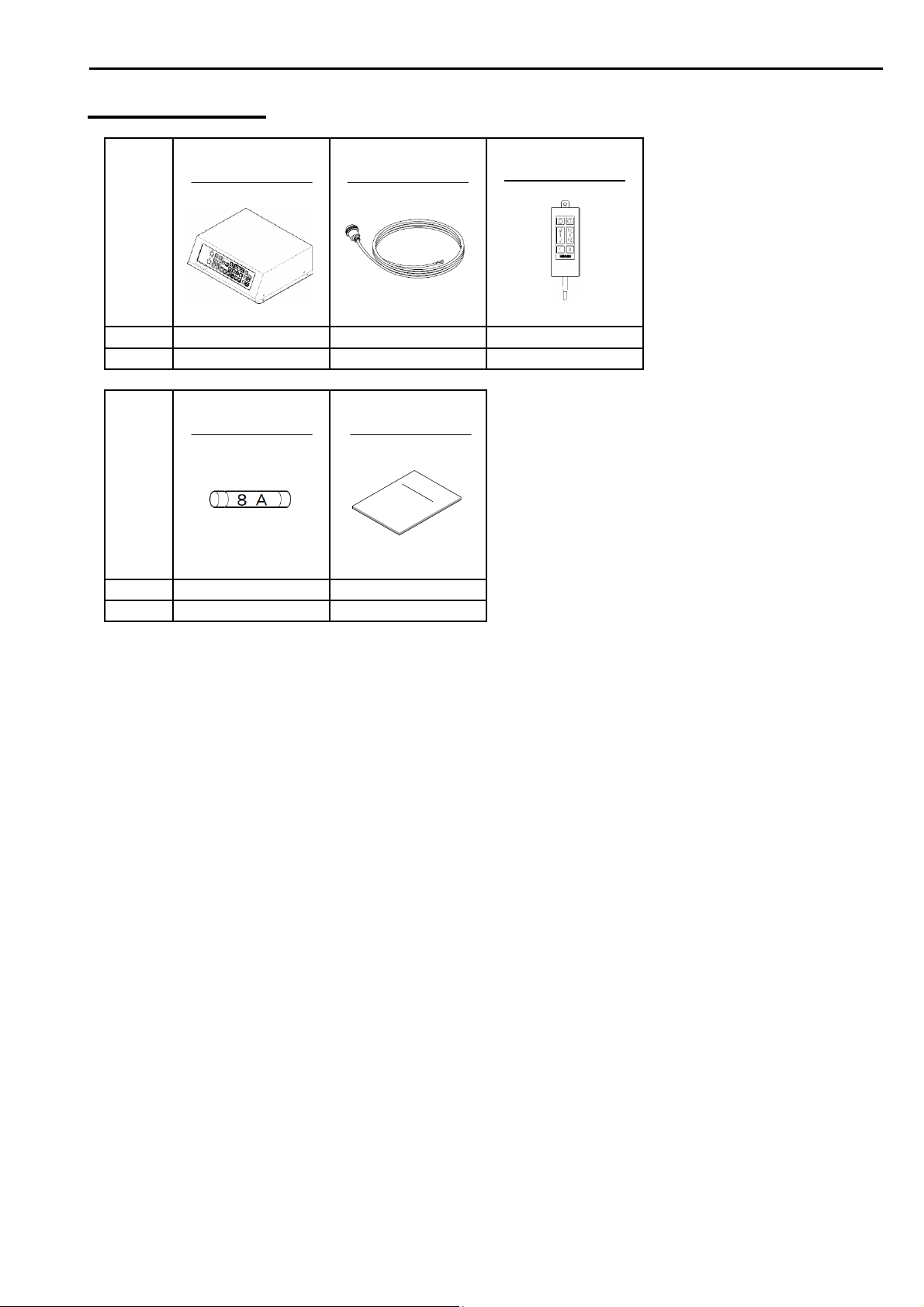
COMPONENTS
Name
of item
Type
Qty
Name
of item
Type
Qty
OPERATION
UNIT
ESR-S1BB CW-206-2M OP-1409
1 1 1
FUSE
F-7161 (8A) ESR-S1BB.OM.E
3 1
POWER SUPPLY
CABLE
2m
OPERATION
MANUAL
COMPONENTS
REMOTE
CONTROLLER
4m
<Continued on next page>
7
Page 11

COMPONENTS
Name
of item
Type
Qty
SL-2 [SET] OPTION
TRANSDUCER
UNIT
Name
of item
Type
Qty
Name
of item
Type
Qty
Name
of item
-
1
Type
Qty
JOINT PIPE
LOCK NUT
- - - - -
1 1 1 1 1
LOW HEAD
CAP BOLT
CAP BOLT
M4x8 M8x16U SW8U N8U B8x25U
4 4 4 2 2
SOUNDOME
- - -
1 50gx1 1EACH
WASHER
RING
SILICONE
ADHESIVE
TD CASE
NUT
HEX. ROD
WRENCH
2.5mm
2mm
2.5m m
6mm
3mm
COVER
BOLT
Name
of item
Type
Qty
PIPE FIXING
HOOK PLATE
PIPE CAP
FASTENING
BAND
RING
STOPPER
- - - - -
1 1 1 1 1
8
Page 12

Chapter 1
SONAR SYSTEM SUMMARY
This chapter provides some basic information of the PPI (Plan Position Indicator)
searchlight sonar.
Sonar Mode……………………………………………………... 1 - 2
Tilt Angle
Tilt Angle and DIsplay………………..….………………. 1 - 5
Bottom Scan Mode.……………………………….……….. 1 - 6
Echo Sounder Mode.……………………………….……... 1 - 7
Sample Display of Sonar Mode………………….. 1 - 8
Sample Display of Bottom Scan Mode………... 1 - 8
Sample Display of Echo Sounder Mode……… 1 - 9
………………………………………………………… 1 - 4
1-1
Page 13
SONAR SYSTEM SUMMARY
SONAR MODE
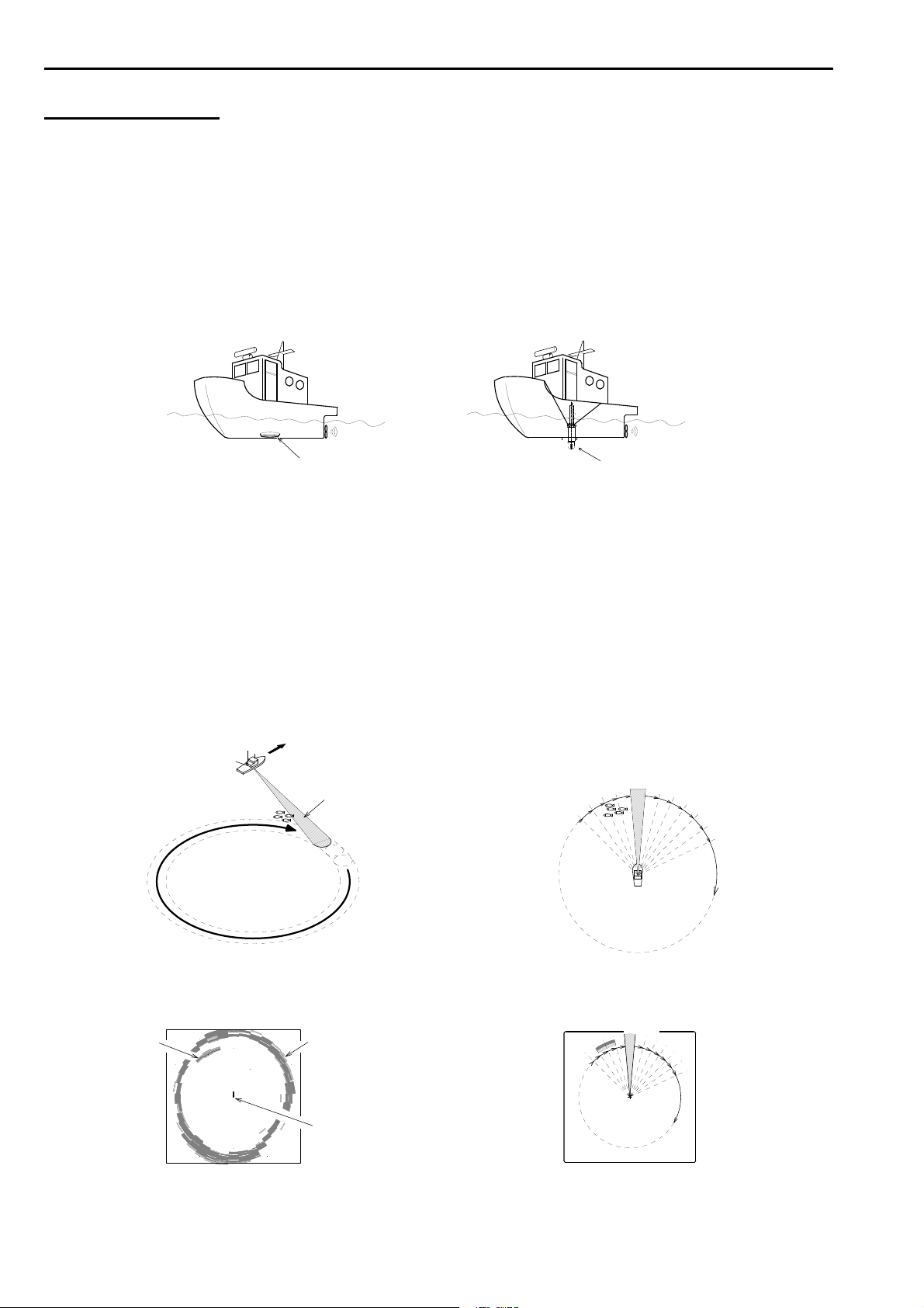
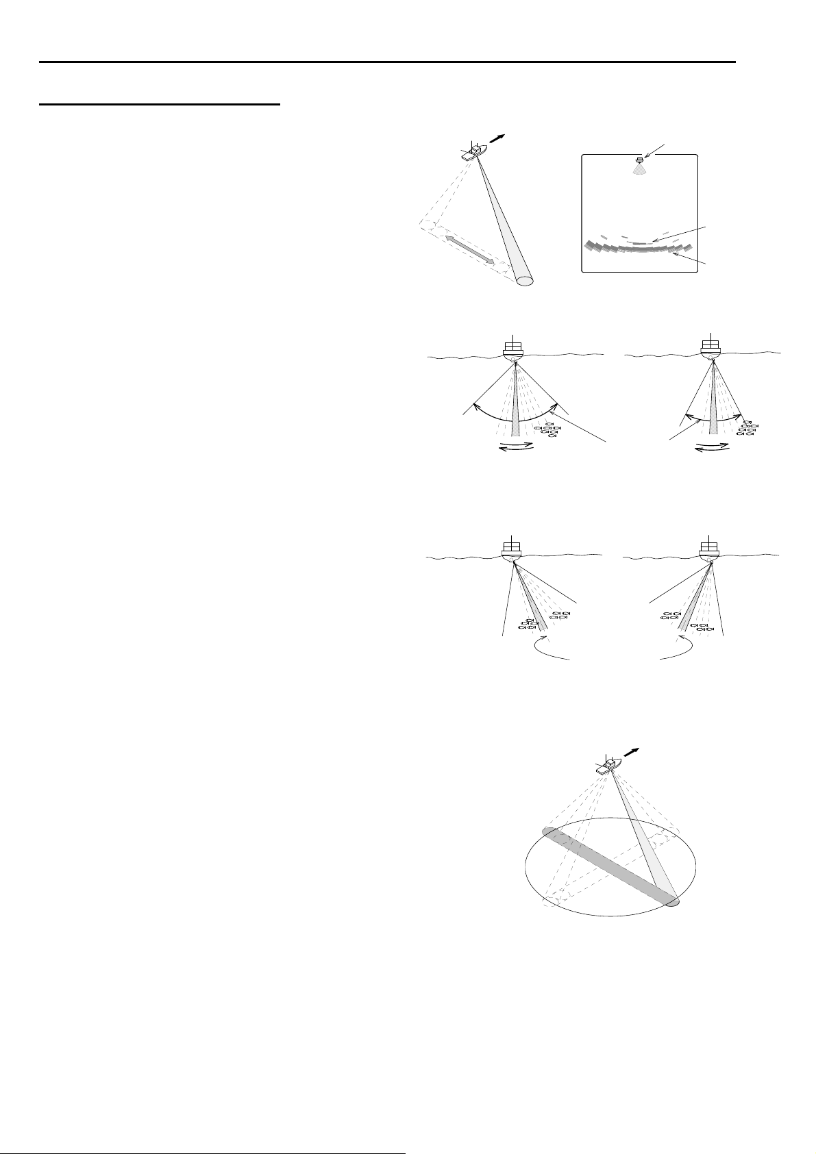
A sonar system uses the transmitter-receiver as well as an echo sounder.
An echo sounder is only able to search in one direction, down.
However a sonar has a movable transducer and therefore can freely search the entire
around a ship, not just the area directly beneath the ship.
When the sonar is not operated, the transducer is retracted.
While operating, the transducer is protruded from the hull bottom.
Echo sounder transducer Sonar transducer
An ultrasonic pulse is emitted from the transducer protruded from the hull bottom.
The sonar principle detected by the transducer is the same with the echo sounder.
However, like a searchlight, the sonar transducer sends and detects ultra-sound
beams one after another while giving relative bearing at some speed in proper ranges.
The transducer scans or trains with the step angle set at MENU.
The seabed and fish school will send a reflected echo of sound back to the ship.
In a PPI sonar, this reflection with relative bearing and range information is presented
like a radar screen.
IMAGE of ULTRA-SOUND BEAMS SEEN
FROM THE TOP
DETECTED RANGE (ultra-sound beam)
DETECTION (TILT ANGLE - 50°)
DISPLAYED PICTURE ON THE SCREEN
FISH SCHOOL SEA BOTTOM
+
OWN SHIP POSITION
1
2
3
4
5
6
7
1
2
3
4
5
6
7
1-2
Page 14
SONAR SYSTEM SUMMARY
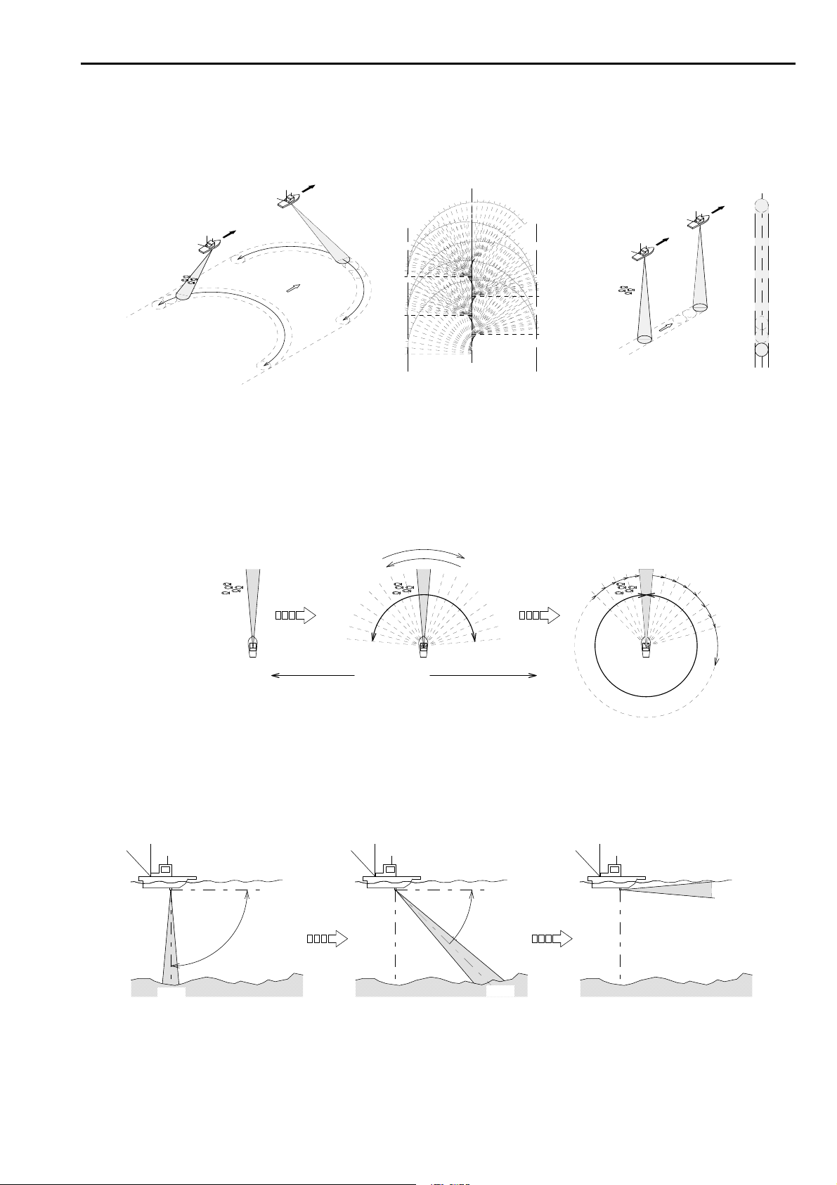
An echo sounder is only able to search in one direction within some beam angle, beneath
the ship. A sonar, however, can freely search the broad range, since the transducer’s
angle can be varied not only the horizontal direction but also the vertical direction.
SONAR DISPLAY RANGE ECHO SOUNDER DISPLAY RANGE
HORIZONTAL ANGLE (SECTOR) 180° WHEN DETECTING
By changing the horizontal angle (Sector), the various ranges from the narrow to the full
circle are available
MIN
[ULTRA-SOUND BEAMS SEEN FROM THE TOP]
SECTOR ANGLE
MAX
By changing the transducer’s directional angle (Tilt), the ultra-sound beam angle can
be varied from right beneath the ship to the horizontal direction.
TILT 0°
TILT –45°
TILT –90°
0゚
SEA BOTTOM
-90゚
0゚
-45゚
1
2
3
4
5
6
7
8
1-3
Page 15
SONAR SYSTEM SUMMARY
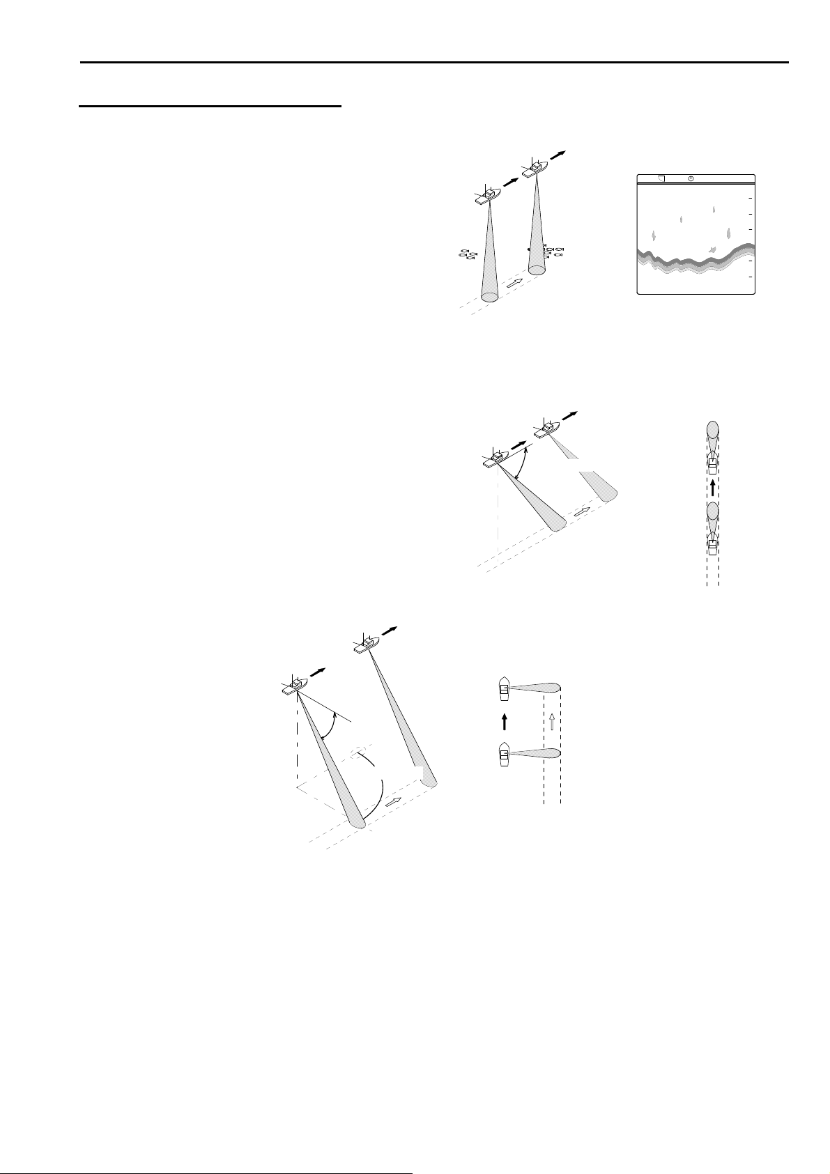
TILT ANGLE
The tilt angle shows the direction to which the sound
wave is emitted. The tilt angle can be set in step of 1°
from 0° to +5° (upward) to 0° to 90° (downward).
Find out the suitable tilt angle for a given depth and
detection range.
The tilt angle is of importance when working with sonar.
Refer to the illustration below. Find out the suitable tilt angle and beam coverage.
When the ship approaches B with the same tilt angle, the reflection is getting smaller
and weaker gradually and nothing appears at B position.
Without changing the tilt angle, the fish school is out of beam coverage at B position
so that no reflection appears on the screen. Set an appropriate tilt angle so that the
reflection of fish school always appears on the screen.
AB AB
SEA BOTTOM SEA BOTTOM
Choose appropriate
tilt angle to target
fish school.
The narrow tilt angle is selected for surface detection, however, if 0° is selected,
sometimes the reflection of the sea surface appears on the screen as the noise and
interferes with observation of wanted echoes.
Adjust an appropriate tilt angle to lessen the affect of sea surface reflection.
If the tilt angle is set to 0゜
the affect of sea surface
reflections appears.
BEAM COVERAGE
Set the tilt angle
wider until the
affect disappears.
The Tilt angle is also set in the Bottom Scan mode and the Echo Sounder mode.
TILT ANGL E
SETTING RANGE
-90゜
BEAM COVERAGE
5゜
0゜
SEA
BOTTOM
1-4
Page 16
SONAR SYSTEM SUMMARY
TILT ANGLE AND DISPLAY
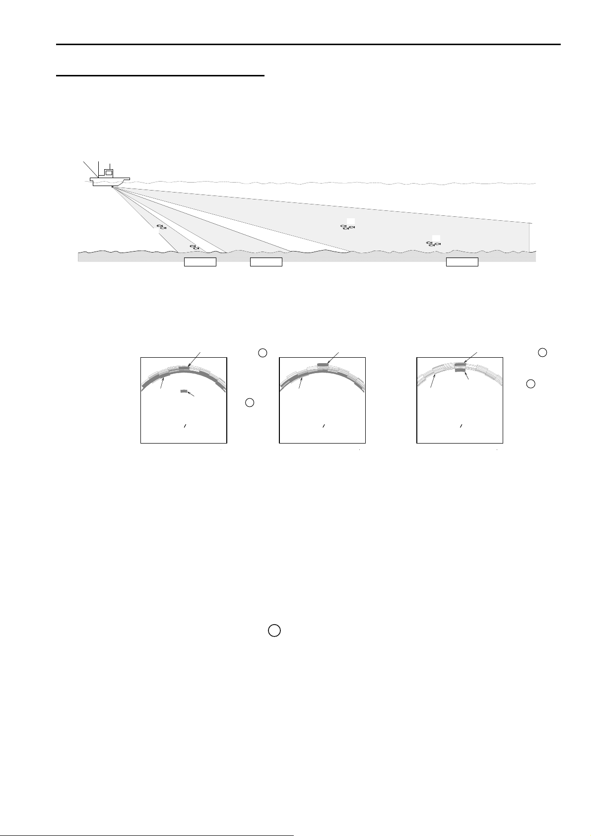
In the shallow water the bottom reflection is prominent, so it is important to be able
to distinguish fish echoes from the bottom echo. Therefore the setting of the tilt angle
is important to find out the suitable tilt angle.
SEA BOTTOM
①
②
-40゜ -25゜
The below shows how fish schools are displayed on the screen when each different
tilt angle set. The below drawings are shown under Off-Center position.
FISH SCHOOL 2 FISH SCHOOL FISH SCHOOL 4
SEA BOTTOM SEA BOTTOM SEA BOTTOM
TILT ANGLE –40° TILT ANGLE –25° TILT ANGLE –10°
FISH SCHOOL 1
• TILT ANGLE 40° :
• TILT ANGLE 25° :
• TILT ANGLE 10° :
Fish school is just above the bottom echo so that it is
hard to discriminate fish echo from the bottom, since the
distances from fish school and from bottom are the same.
Fish school is clearly seen. Fish school is displayed
behind the bottom echo, since fish school is in the area
of weak reflection of bottom echo.
Bottom echo is weak so that fish school is easily seen.
Due to the density of fish school the strong reflection of fish
school is easily displayed on the screen.
Fish school 3 is actually in the middle layer, however it is
displayed likely to be near the bottom echo on the screen.
③
④
-10゜
FISH SCHOOL 3
+++
NOTE !---------------------------------------------------------------------------------------------------------
The explanation mentioned above is extremely general explanation, and it is
not a thing satisfying all conditions, which is different depending on the
situation of the sea and a state of the bottom of the sea, setting of sensitivity
and so on.
----------------------------------------------------------------------------------------------------------------------
1-5
Page 17
SONAR SYSTEM SUMMARY
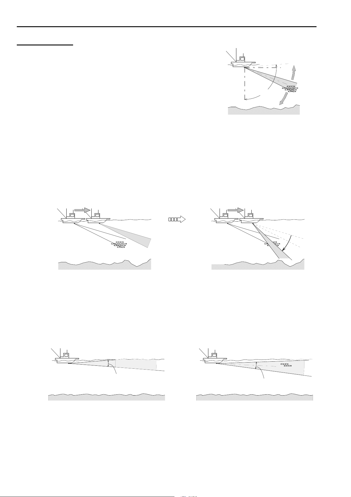
BOTTOM SCAN MODE
When this mode is selected, the transmitter/
receiver does not rotate like a sonar, but
sweeps from side to side like a pendulum
when the sound wave is emitted.
The reflected echo from the sea
bottom is displayed on the screen
sequentially.
When the bottom scan mode is selected,
it sweeps from side to side in the step set
with STEP on MENU - DISP ITEM SEL.
Changing the sector angle makes it
possible to detect the wider or narrower
range as desired.
The center direction of the sounding beam
can be changed with the tilt angle.
Choose the setting of the tilt angle which
places the sector center in the middle of the
detection range.
In the bottom scan mode the detectable
direction is provided not only rightward
or leftward, but also in the direction of
360° by setting the direction of the transducer.
OWN SHIP POSITION
FISH
SCHOOL
SEA
BOTTOM
SECTOR ANGLE
CENTER OF SECTOR
1-6
Page 18
ECHO SOUNDER MODE
The transmitter/receiver faces the sea bottom,
and emits the ultra-sound beam. The reflected
echo from the sea bottom is displayed on
the screen. The image is displayed like a
usual echo sounder.
The tilt angle and the direction can be changed.
The detecting direction can be set by
the Bearing keys.
TILT ANGLE
DIRECTION
SONAR SYSTEM SUMMARY
ECHO SOUNDER DISPLAY
DETECTS DIRECTLY UNDER THE SHIP
CHENGES THE TILT ANGLE
TILT ANGLE
CHENGES THE TILT ANGLE AND DIRECTION
1-7
Page 19
SONAR SYSTEM SUMMARY
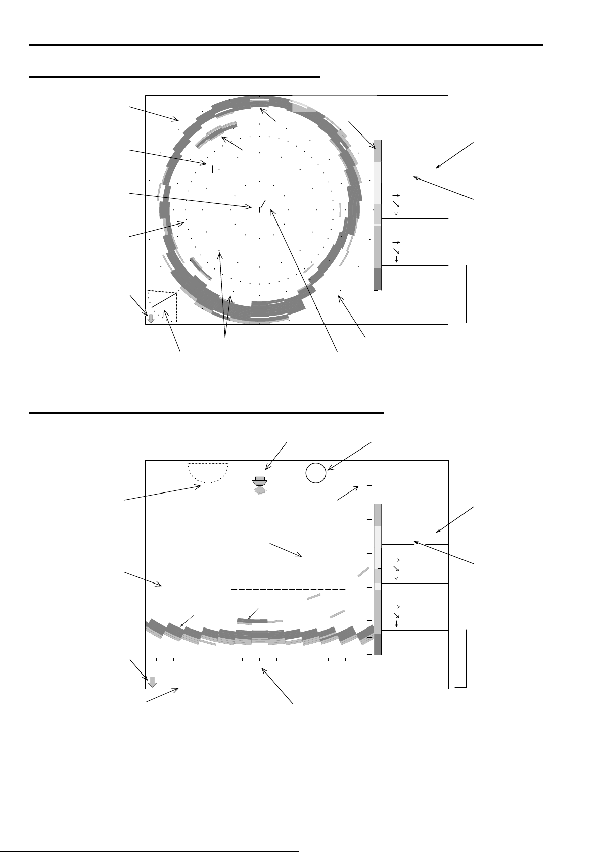
SAMPLE DISPLAY OF SONAR MODE
COMPASS DISP.
COLOR SCALE
CROSS CURSOR MODE
ECHO
S
SEA BOTTOM OPERATION
W
SHIP’S POSITION
INTERFERENCE
REDUCTION
MARKER
SOUNDOME
POSITION
E
N
SCALE COMPASS DISP.
TIL T ANGLE BEARING LINE
RANGE
160m
BEARING
0゜
SECTOR
360゜
TILT
-30゜
IR-1 M-0-1
MARKER
86.0m
99.3m
49.7m
CURSOR
十305゜
65.2m
75.3m
37.7m
24.7゜C
16.0kt
34゜
33.40’N
137゜
03.84’E
WATER TEMP.
SPEED
LATITUDE
LONGITUDE
SAMPLE DISPLAY OF BOTTOM SCAN MODE
SHIP’S POSITION SCANNING DIRECTION
TILT ANGLE SCALE
(RANGE) OPERATION
MODE
CROSS CURSOR
VRM
REDUCTION
SEA BOTTOM ECHO
100
SOUNDOME
POSITION SPEED
LONGITUDE
138
32 0 32 64 966496
m
DEPTH SCALE (SECTOR)
※ “IR” will not be displayed when INTER FERENCE RED. function “OFF” is selected.
※ “M-” will not be displayed if OPERATION MODE is not used.
※ To present WATER TEMP./SPEED/LAT/LON/COMPASS DISP. info will require ESR-S1BB is
connected to an external equipment.
0
32
64
96
128
160
RANGE
160m
BEARING
270゜
SECTOR
95゜
TILT
-90゜
IR-1 M-0-1
MARKER
----m
----m
----m
CURSOR
十-70゜
25.7m
75.1m
70.6m
24.7゜C
16.0kt
34゜
33.40’N
137゜
03.84’E
INTERFERENCE
WATER TEMP.
LATITUDE
1-8
Page 20
SONAR SYSTEM SUMMARY
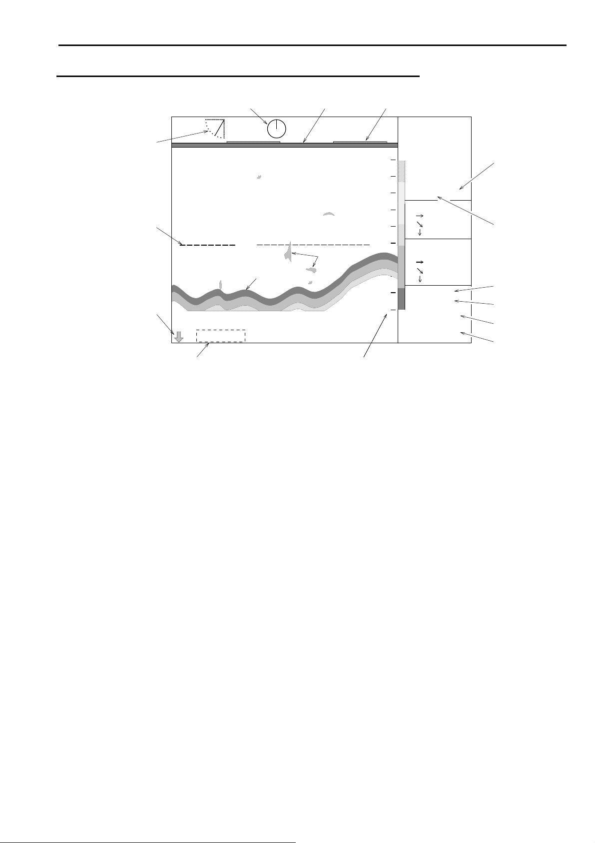
SAMPLE DISPLAY OF ECHO SOUNDER MODE
DIRECTION SURFACE TIME MARKER
0
32
64
96
128
160
RANGE
160m
BEARING
0゜
SECTOR
---゜
TILT
-60゜
IR-1 M-0-1
MARKER
50.4m
100m
87.2m
CURSOR
十 ---゜
----m
----m
----m
24.7゜C
16.0kt
34゜
33.40’N
137゜
03.84’E
MODE
INTERFERENCE
WATER TEMP.
SPEED
LATITUDE
LONGI TUDE
TILT ANGLE
OPERATION
VRM
REDUCTION
SEA BOTTOM
100
ECHO
SOUNDOME
POSITION
DEPTH SCALE (RANGE)
※ The depth is displayed when the tilt angle is -90°.
※ “IR” will not be displayed when INTER FERENCE RED. function “OFF” is selected.
※ “M-” will not be displayed if OPERATION MODE is not used.
※ To present WATER TEMP./SPEED/LAT/LON/COMPASS DISP. info will require ESR-S1BB is
connected to an external equipment.
1-9
Page 21

Chapter 2
SONAR OPERATION
This chapter provides you the description of operation dials and keys for the ESR-S1BB Sonar.
Operation Panel………………………………………………………….. 2 - 2
Key Operation……………………………………………………………. 2 - 2
Operation Keys 2 - 3
Power On/Off Key………………..………………………………… 2 - 3
Sonar Mode key……………………………………………………. 2 - 4
Off Center Mode Key....…………………...………………………. 2 - 4
Bottom Scan / Echo Sounder Mode Key………………………... 2 - 4
Bearing Keys……………………………………………………….. 2 - 5
Tilt Keys…………………………………………………………….. 2 - 6
Sector Keys………………………………………………………… 2 - 8
Range Keys………………………………………………………… 2 - 9
Operation Mode Keys.…………………………………………….. 2 - 10
Cursor Keys………………………………………………………... 2 - 11
Target Lock Key……………………………………………………. 2 - 13
Threshold Key……………………………………………………… 2 - 13
Menu Key…………………………………………………………… 2 - 14
Enter Key……………………………………………………………. 2 - 14
Operation Dials 2 - 15
Gain Dial……………………………………………………………. 2 - 15
Far Gain Dial……………………………………………………….. 2 - 15
2-1
Page 22
SONAR OPERATION
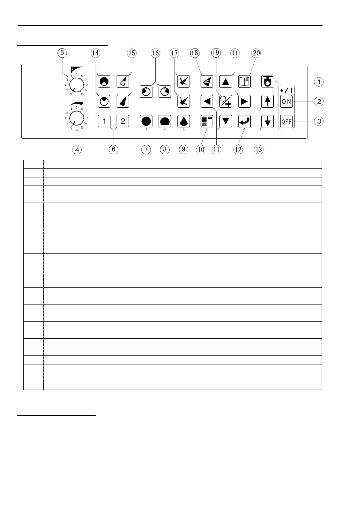
OPERATION PANEL
No. NAME ACTION
1 SENSOR LAMP Non use
2 POWER ON KEY Turns on the power.
3 POWER OFF KEY To turn off the power, press this key for a while.
This key doesn’t work by one-push.
4 GAIN DIAL Adjusts the receiver sensitivity.
5 FAR GAIN DIAL Adjusts the receiver sensitivity for the long ranges and
STC function.
6 OPERATION MODE KEYS Calls up the user-defined setting or changes the
settings.
7 SONAR MODE KEY Sonar Mode.
8 OFF CENTER MODE KEY Off-Center Mode.
9 BOTTOM SCAN
MODE KEY
10 THRESHOLD KEY Reduces the unnecessary weak echoes accordingly.
11 CURSOR SHIFT KEYS Moves the cursor or selects to display Marker or
12 ENTER KEY Press this key to set the function setting.
13 HOIST KEYS This key is no operation.
14 SECTOR KEYS Adjusts the sector angle.
15 RANGE KEYS Selects a desired range scale.
16 BEARING KEYS Moves the cursor center right or left.
17 TILT KEYS Adjusts tilt angle.
18 TARGET LOCK KEY Turns on or off the target lock mode.
19 CURSOR
SELECTION KEY
20 MENU KEY Displays the function set menu.
Bottom Scan Mode.
Cursor. Use these keys to change the settings.
Selects Ring Marker or Cross Marker.
KEY OPERATION
After pressing a key, a beep sounds when a correct key operation is done.
Three short beeps sound when a wrong key is pressed.
2-2
Page 23

SONAR OPERATION
OPERATION KEYS
POWER ON/OFF KEY
To turn on the power, press [ON] key.
To turn off the power, press [OFF] key for a while. This key does not work by one-push.
2-3
Page 24

SONAR OPERATION
SONAR MODE KEY
Displays the Sonar Mode.
RANGE
BEARING
SECTOR
TILT
+
SHIP’S POSITION
MARKER
CURSOR
Tilt angle is adjusted by the Tilt keys.
Sector angle is adjusted by the Sector
keys.
The scanning direction is adjusted by
the Bearing keys.
OFF CENTER MODE KEY
Displays the Off-Center Mode.
RANGE
BEARING
SECTOR
TILT
MARKER
SHIP’S POSITION
+
CURSOR
It allows showing more information
ahead (rightward) by moving the ship’s
position downward (leftward)
on the screen.
BOTTOM SCAN / ECHO SOUNDER MODE KEY
Displays the Bottom Scan Mode or the Echo Sounder Mode.
SHIP’S POSITION
RANGE
BEARING
SECTOR
TILT
MARKER
CURSOR
BOTTOM SCAN MODE ECHO SOUNDER MODE
The scanning direction is adjusted by the Bearing keys. CF page 2-5
Tilt angle is adjusted by the Tilt keys. CF page 2-6/2-7
Sector angle is adjusted by the Sector keys in Bottom Scan Mode. CF page 2-8
RANGE
BEARING
SECTOR
TILT
MARKER
CURSOR
CF page 2-6
CF page 2-8
CF page 2-5
CF page 3-11
2-4
Page 25

SONAR OPERATION
BEARING KEYS
Use these keys to define the center of current scanning sector in the Sonar Mode.
The bearing angle of the display is shifted with every 5° steps.
Displays the center of
Rotates the center of Rotates the center of the sector angle.
the sector counterclockwise. the sector clockwise.
Changes the center direction.
This arrow marks the
center of the sector.
Use these keys to define the center of current scanning sector in the Bottom Scan Mode.
The bearing angle of the display is shifted with every 5° steps.
Counterclockwise rotation Clockwise rotation
Display of the scanning direction
Displays the scanning
direction of the bow.
Displays your own ship
direction at every 90°
off the record.
Use these keys to define the scanning direction in the Echo Sounder Mode.
The bearing angle of the display is shifted with every 5° steps.
RANGE
BEARING
SECTOR
TILT
MARKER
CURSOR
2-5
Page 26

SONAR OPERATION
TILT KEYS
Use these keys to control the tilt angle in the Sonar Mode.
The tilt angle can be set in increments of 1° from 0° to 5° (upward) to 0° to 90°
(downward).
Changes this angle.
Each press of this key moves
the tilt angle upwards. Displays the values
of the tilt angle.
Each press of this key moves
the tilt angle downwards.
-90゜
Use these keys to control the scanning center direction of the detection range in the
Bottom Scan Mode.
Variable range in increments of 3° step: -3° ~ -90° and -3° on another side
Variable range in increments of 5° step: -5° ~ -90° and -5° on another side
(Refer to the page 3-11 for steps)
The angle center is just The center is set in the The center is set in the
under your own ship. range shown by an arrow. range shown by an arrow.
Your own Your own Your own
ship position ship position ship position
(center) (right) (left)
Depth, just under
your own ship
5゜
0゜
Displays the angle
in a diagram.
Displays the tilt angle in a diagram.
Just under your own ship (-90°)
RANGE
BEARING
SECTOR
TILT
MARKER
CURSOR
Changes the tilt angle
and the center direction.
Each press of this key
moves the tilt angle
clockwise.
Each press of this key
moves the tilt angle
counterclockwise.
2-6
Page 27

SONAR OPERATION
Use these keys to control the tilt angle in the Echo Sounder Mode.
The tilt angle can be set in increments of 1° from 0° to 5° (upward) to 0° to 90°
(downward).
This angle is adjusted
by the tilt keys.
Direction is adjusted
by the bearing keys.
Use VRM to read the depth if the tilt angle is not -90°.
(Refer to the page 2-11 for VRM).
TILT
The depth is displayed when the tilt angle is - 90°.
DIRECTION
RANGE
BEARING
SECTOR
TILT
MARKER
CURSOR
DIRECTION ANGLE
TILT ANGLE
2-7
Page 28

SONAR OPERATION
SECTOR KEYS
Changes the sector angle (horizontal angle) in the Sonar Mode.
Changes this angle.
Each press of the Sector key widens the sector angle.
Each press of the Sector key narrows the sector angle.
8 selectable sector angles in the Sonar Mode
5° STEP 5° 25° 45° 85° 125° 165° 205° 360°
10° STEP 10° 30° 50° 90° 130° 170° 210° 360°
Changes the sector angle (vertical angle) in the Bottom Scan Mode.
Changes this angle.
Each press of the Sector key widens the sector angle.
Each press of the Sector key narrows the sector angle.
8 selectable sector angles in the Bottom Scan Mode
3° STEP 3° 27° 45° 63° 93° 117° 147° 177°
5° STEP 5° 25° 45° 65° 95° 115° 145° 175°
Displays the selected angle.
RANGE
BEARING
SECTOR
TILT
MARKER
CURSOR
(Refer to the page 3-10 for steps)
(Refer to the page 3-11 for steps)
2-8
Page 29

SONAR OPERATION
RANGE KEYS
Changes the basic range (the basic depth)
Displays the selected values and units.
Changes this distance.
SCALE MARKER
20 selectable ranges are available.
Each press of the Range key makes the range value smaller.
Each press of the Range key makes the range value larger.
The setting for the depth unit is accessed by using “FUNCTION SETTINGS.”
Scale marker can be turned on or off by using “FUNCTION SETTINGS.”
BASIC RANGE
m br/fm
BOTTOM
RANGE
SONAR
OFF
CENTER
SCAN /
ECHO
SOUNDER
0 10 15 10 10 15 10
1 20 30 20 20 30 20
2 30 45 30 30 45 30
3 40 60 40 40 60 40
4 50 75 50 50 75 50
5 60 90 60 60 90 60
6 70 105 70 70 105 70
7 80 120 80 80 120 80
8 90 135 90 90 135 90
9 100 150 100 100 150 100
10 120 180 120 110 165 110
11 140 210 140 120 180 120
12 160 240 160 130 195 130
13 180 270 180 140 210 140
14 200 300 200 150 225 150
15 220 330 220 160 240 160
16 240 360 240 170 255 170
17 260 390 260 180 270 180
18 280 420 280 190 285 190
19 300 450 300 200 300 200
RANGE
BEARING
SECTOR
TILT
MARKER
CURSOR
SONAR
CF page 3-15
CF page 3-12
OFF
CENTER
BOTTOM
SCAN /
ECHO
SOUNDER
2-9
Page 30

SONAR OPERATION
OPERATION MODE KEYS
Use these keys to select one of 2 kinds of operation mode you have created. (You may
be able to create 4 kinds of operation mode by FUNCTION SETTINGS. CF page 3-15)
By pressing one of these keys, the desired operation mode can be set immediately.
To memorize the setting in the Operation Mode key, the following procedure is required.
Create your own setting of operation mode.
Exit Menu.
Hold the Operation Mode [1] or [2] key for 3 seconds until you hear a beep. The operation
mode that you have created is now memorized in the Operation Mode key. Note that it may
not be memorized when the key is released before you hear a beep.
By pressing the Operation Mode [1] or [2] key, you hear a beep and the desired operation
mode appears on the screen instantly. Note that you hear 3 beeps and nothing changes
when pressing the Operation Mode [1] or [2] key memorized nothing.
You may adjust the setting while one of the operation modes works, however pressing one
of the Operation Mode keys again returns to the previous operation mode.
It is possible to memorize the present setting in the Operation Mode keys by holding the key
for 3 seconds.
The Operation Mode key number appears on the screen.
RANGE
160m
BEARING
SECTOR
TILT
IR-1 M-0-1
MARKER
CURSOR
24.7゜C
16.0kt
33.40’N
137゜
03.84’E
0゜
360゜
-30゜
86.0m
99.3m
49.7m
十305゜
65.2m
75.3m
37.7m
34゜
indicates the function setting number you
selected.
indicates the Operation Mode key number you
selected.
2-10
Page 31

SONAR OPERATION
CURSOR KEYS
By using these keys, the horizontal range, depth and bearing to the target can be
measured.
Use [Cursor Selection] key to select a cursor and [ ↑ ] [↓ ][←][→] keys move the cursor in
any direction on the screen.
:activates either Ring Marker or Cross Cursor in the Sonar Mode.
:activates either VRM or Cross Cursor in the Bottom Scan Mode.
:activates either VRM in the Echo Sounder Mode.
:expands the Ring Marker, shifts the Cross Cursor upward, or shifts VRM to
the shallow.
:moves the highlighted item upward in the Menu.
:contracts the Ring Marker, shifts the Cross Cursor downward, or shifts
VRM to the deeper area.
:moves the highlighted item downward in the Menu.
:shifts the Cross Cursor left.
:selects the content of the item in the Menu.
:shifts the Cross Cursor right.
:selects the content of the item in the Menu.
The Ring Marker or the Cross Cursor neither appears nor operates on the screen when turning
on the power at the very first time.
The Marker appears by pressing either [ ↑ ] or [ ↓ ] key, and then select the Ring Marker or
the Cross Cursor by [Cursor Selection] key.
The inactive function is displayed in red and stored even if the power is turned off.
Press [ ↑ ] and [ ↓ ] keys at the same time to turn the Marker off.
Pressing [ ↑ ] or [ ↓ ] key again returns the Marker to the previous position.
2-11
Page 32

SONAR OPERATION
When the Ring Marker is selected (the Cross Cursor is in red or not displayed,)
SONAR MODE
:HORIZONTAL DISTANCE (“a” in the below drawing)
MARKER
レンジ
旋回中心
セクター
俯角
マーカー
十字カーソル
Changes this range.
BOTTOM SCAN MODE ECHO SOUNDER MODE
30.5
MARKER & DEPTH MARKER & SLANT DISTANCE
In Bottom Scan Mode Marker data
is not presented and VRM appears
on the screen.
When the Cross Cursor is selected (the Ring Marker is in red or not displayed,)
Set the Cross Cursor on a target by using the Cursor Shift [ ↑ ][ ↓ ][←][→] keys, and the
depth and horizontal/slant distance to the target are displayed in the Cursor box.
SONAR MODE BOTTOM SCAN MODE
+
CROSS CURSOR CROSS CURSOR
RANGE
BEARING
SECTOR
TILT
MARKER
CURSOR
:SLANT DISTANCE (“b” in the below drawing)
:DEPTH (“c” in the below drawing)
This key lengthens the distance.
This key shortens the distance.
a
c
b
a
MARKER DISTANCE
RANGE
BEARING
SECTOR
TILT
MARKER
CURSOR
:HORIZONTAL DISTANCE
:SLANT DISTANCE
:DEPTH
MARKER UP
c
b
32. 5
32.5
MARKER DOWN
In Echo Sounder Mode Marker data
is presented and Slant distance
appears on the screen.
RANGE
:BEARING :BEARING
:HORIZONTAL DISTANCE :HORIZONTAL DISTANCE
:SLANT DISTANCE :SLANT DISTANCE
:DEPTH :DEPTH
BEARING
SECTOR
TILT
MARKER
CURSOR
2-12
Page 33

SONAR OPERATION
TARGET LOCK KEY
When pressing the Target Lock key in the Sonar Mode, the direction of sweep of the sonar
beam is reversed. (When MENU / TARGET LOCK / MODE 0 is selected.)
When pressing the Target Lock key in the Sonar Mode, the sonar beam tracks the echo
automatically. (When MENU / TARGET LOCK / MODE 1 or MODE 2 is selected.)
The red-letter “TARGET LOCK” is displayed at the position of both “BEARING” and “SECTOR”
on the screen right.
Please refer to page 3-13 for more details of the Target Lock operation.
THRESHOLD KEY
The weak echoes disappear by pressing this key accordingly.
Only strong wanted targets appear on the screen by pressing this key to erase unwanted
returns such as plankton or noise.
Each press of Threshold key clears the weakest color sample.
COLOR SCALE
+
RANGE
BEARING
SECTOR
TILT
MARKER
CURSOR
RANGE
BEARING
SECTOR
TILT
MARKER
CURSOR
RANGE
BEARING
SECTOR
TILT
MARKER
CURSOR
RANGE
BEARING
SECTOR
TILT
MARKER
CURSOR
RANGE
BEARING
SECTOR
TILT
MARKER
CURSOR
Each press of this key 7 colors 6 colors 5 colors 4 colors 3 colors 2 colors
changes the color
sample as shown right.
RANGE
BEARING
SECTOR
TILT
MARKER
CURSOR
2-13
Page 34

SONAR OPERATION
MENU KEY
Use this key to set the basic functions.
Pressing this key displays MAIN MENU
MAIN MENU
on the right of the screen.
Refer to Chapter 3 “FUNCTION
+
SETTINGS” for more details.
By pressing this key again, MAIN MENU
disappears.
Pressing this key returns to MAIN MENU when the setup menu is displayed.
Use the Enter key to set the function item you changed.
ENTER KEY
After you change the settings in the setup menu, press this key.
Note that the content of the settings is not changed when you exit MAIN MENU by pressing
the Menu key even if you set the function items.
2-14
Page 35

OPERATION DIALS
GAIN DIAL
5
4
10
0
5
4
10
0
5
4
010
6
7
8
9
6
7
8
9
6
7
8
9
3
2
1
FAR GAIN DIAL
3
2
1
3
2
1
SONAR OPERATION
Adjusts the sensitivity of the received signal and turn this dial
Clockwise to increase the gain.
Gain controls can be adjusted by “GAIN UP” function in
FUNCTION SETTINGS.
TVG CURVE in FUNCTION SETTINGS
10LOG ~ 40LOG
As the echoes returning from the bottom and from fish targets
get weaker as the depth increases, it is advantageous to have a
Time-varied-gain function that automatically compensates for
propagation loss of sound. CF page 3-7
STC function in TVG CURVE in FUNCTION SETTINGS
This STC function enables you to reduce noise interference
resulting from bubbles, dirt, etc. near the surface of the water.
As the dial is turned toward “0”, then the STC effect will
become progressively from the surface to the distance stronger.
Selecting STC function releases the gain adjustment
automatically so that the sensitivity of the receiver becomes
weaker in the distance.
Gain controls can be adjusted by the Gain Dials and “GAIN UP”
function in FUNCTION SETTINGS.
CF page 3-6
CF page 3-6
2-15
Page 36

Chapter 3
FUNCTION SETTINGS
This chapter provides you the main functions of the ESR-S1BB Sonar and describes the
primary controls. It also suggests settings to use for initial start up.
Initial Settings 3 - 1
Factory Settings…………………………………………………. 3 - 2
Return to Factory Settings…………………...………………... 3 - 3
User Settings………...………………………………………….. 3 - 3
Menu
Function Set Menu…….……………………………………….. 3 - 4
Function Settings
Setting Functions…………………………………………… 3 - 5
Gain Up………………………………………………………… 3 - 6
TVG Curve…………………………………………………….. 3 - 7
Dynamic Range………………………………………………. 3 - 7
Pulse Width……………………………………………………. 3 - 8
TX Power……………………...………………………………. 3 - 8
Reduction 3 - 9
Interference Reduction………………………………………. 3 - 9
Noise Reduction……………………………………………… 3 - 9
Display Item Selection 3 - 10
Step (Sonar)…………………………………………………... 3 - 10
Step (Bottom Scan)………………………………………….. 3 - 11
Off-Center Position…………………………………………… 3 - 11
Scale Display…………………………………………………. 3 - 12
Compass Display…………………………………………….. 3 - 12
Others 3 - 13
Target Lock……………………………………………………. 3 - 13
Operation Mode………………………………………………. 3 - 15
Depth Unit……………………………………………………... 3 - 15
Temperature Unit……………………………………………... 3 - 15
Speed Unit…………………………………………………….. 3 - 15
Train Correct………………………………………………….. 3 - 16
Color……………..……………………………………………..
Filter……………..……………………………………………..
3 - 17
3 - 18
3-1
Page 37

FUNCTION SETTINGS
INITIAL SETTINGS
FACTORY SETTINGS
The ESR-S1BB is shipped from the factory with the functions under the settings listed
below.
Before using it, please enter the functions to the desired setup.
FUNCTIONS FACTORY SETTINGS (in the item )
FUNCTION SET
GAIN UP
TVG CURVE
DYNAMIC RANGE
PULSE WIDTH
TX POWER
REDUCTION
INTERFERENCE RED.
NOISE REDUCTION
DISP ITEM SEL.
STEP (SONAR)
STEP (BOTTOM SCAN)
OFF-CENTER POS.
SCALE DOTS
COMPASS DISP.
OFF • +10dB • +20dB • +30dB • +40dB
OFF • 10LOG • 20LOG • 30LOG • 40LOG
1dB • 2dB • 3dB
NARROW • NORMAL • WIDE • 0.3ms
LOW • HIGH
OFF • 1 • 2 • 3
OFF • ON
5°• 10°
3°• 5°
FORE • BACK • RIGHT • LEFT
OFF
• ON
OFF
• ON
CF page 3-5
CF page 3-9
CF page 3-10
OTHERS
TARGET LOCK
OPERATI ON MODE
DEPTH UNIT
TEMP. UNIT
SPEED UNIT
TRAIN CORRECT
COLOR
FILTER
OPERATI ON MODE 1 • 2
USER SETTINGS
MODE 0
• MODE 1 • MODE 2
0 • 1
m • br • fm • ft
°C •°F
kt • km/h
0°~ 355°
A-1 • A-2 • B-1 • B-2 • C-1 • C-2
OFF • 1 • 2
NO SETTINGS
NO SETTINGS
3-2
CF page 3-13
Page 38

FUNCTION SETTINGS
RETURN TO FACTORY SETTINGS
First press the Power [OFF] key, then press [ON] key while pressing both the Bearing
keys [←][→] at the same time.
Keep pressing the Bearing keys [←][→] until the beep sound stops.
Activating this operation will erase all settings excluding "Train Correct" at
FUNCTION SETTINGS, and restore the basic settings from the factory.
USER SETTINGS
Being separated from the Factory Setting function, Settings may be entered by the user
and memorized. This function is called "User Settings". By entering "User Settings"
the ESR-S1BB to suit individual needs can be done. This not only simplifies operation
of the ESR-S1BB, but also adds considerably to its reliability.
All user-implemented data in the ESR-S1BB can be erased by making a reset of the
unit and thus return to "User settings". Please ensure the "User settings" are
memorized on the first operation.
1. MEMORIZE USER SETTINGS
First ensure the functions are at the desired settings.
After disconnecting the power supply once by pressing the Power [OFF] key, then
turn the power supply back on, while pressing both the Operation Mode [1] and the
Power [ON] keys at the same time. Keep pressing [1] and [ON] keys until the beep
sound stops.
After completing this operation all functions and their units will be memorized as set by
the user.
2. RETURN TO USER SETTINGS
In case, for some reason, the ESR-S1BB becomes inoperable, the unit can be reset
by disconnecting the power supply and then turn the power supply back on, while
pressing the Operation Mode [2] and the Power [ON] keys at the same time. Keep
pressing [2] key until the beep sound stops.
This operation can return to “User Settings.”
3. CHANGING USER SETTINGS
To change the functions in User Settings first activate "Return to Factory Settings"
and then memorize "User Settings" again as described in the previous item 1.
NOTE !---------------------------------------------------------------------------------------------------------
Releasing the keys before the beep sounds stops may not complete the
above-mentioned settings. Performing "Return to Factory Settings" will
return all settings to Factory Settings and erase all User Settings.
----------------------------------------------------------------------------------------------------------------------
3-3
Page 39

FUNCTION SETTINGS
MENU
FUNCTION SET MENU
Basic functions may be briefly described in the following.
Before first using the ESR-S1BB, customizing the functions to suit individual needs.
The following function items can be customized in the function set menu.
MAIN MENU
FUNCTION SET
:GAIN UP
:TVG CURVE
:DYNAMIC RANGE
:PULSE WIDTH
:TX POWER
REDUCTION
:INTERF RED (INTERFERENCE REDUCTION)
:NOISE REDUCTION
DISP ITEM SEL (DISPLAY ITEM SELECTION)
:STEP (SONAR)
:STEP (BOTTOM SCAN)
:OFF-CENTER POS. (OFF-CENTER POSITION)
:SCALE DOTS
:COMPASS DISP. (COMPASS DISPLAY)
OTHERS
:TARGET LOCK
:OPERATION MODE
:DEPTH UNIT
:TEMP. UNIT
:SPEED UNIT
:TRAIN CORRECT
:COLOR
:FILTER
REMOTE CONTROLLER
3-4
Page 40

FUNCTION SETTINGS
FUNCTION SETTINGS
Press the Menu key to display the menu below.
Use the Cursor Shift key [ ↑ ] or [ ↓ ] to highlight the item you wish to change.
By pressing the Cursor Shift key [←] or [→] the following is displayed.
MAIN MENU Use the Cursor Shift key [ ↑ ] or [ ↓ ]
FUNCTION SET to highlight the item you wish to change.
REDUCTION
DISP ITEM SEL. The setup display is accessed by
OTHERS pressing the Cursor Shift key [←] or [→].
REMOTE CONTROLLER
---------------------------------Frequency and Version No. of EPROM
-----------SELF CHECK FUNCTION
The test result NG in red is displayed
ESR-S1BB
S-1400 200kHz
****/**/**
Ver *.***
SELF CHECK
HOIST OK
TRAIN OK
in case of some troubles.
SETTING FUNCTIONS
FUNCTION SET
GAIN UP OFF
TVG CURVE 30 LOG
DYNAMIC RANGE 3 d B ….…………..
PULSE WIDTH NORMAL
TX POWER HIGH
GAIN
H
------------------
L
GAIN00 FAR GAIN00
G0 T0
0 10 100 1000m
Use the Cursor Shift key [ ↑
] or [ ↓ ]
to highlight the item you wish to
change.
Press [←] or [→] key to select the
desired
setting.
Graph for Gain Characteristics
displays the changed gains such as
TVG curve, Gain Up, Gain dial and
Far Gain dial, etc.
3-5
Page 41

FUNCTION SETTINGS
1. GAIN UP
This function makes it possible to display a clearer picture of the full range and control the
sensitivity at various depths.
Each press of [←] or [→] key changes the setting, "OFF, +10dB, +20dB, +30dB,
+40dB."
Select the desired value, and then press the Enter key.
GAIN DIAL VOLUME RANGE
0
WEAK GAIN STRONG
MIN GAIN TOTAL GAIN VOLUME RANGE MAX GAIN
When the menu gain adjust setting is changed from “OFF” to “+10dB,” the gain dial
volume increases 3 points on the scale.
When the menu gain adjust setting is “OFF” and the front panel dial is on “3,” it has the
same result as when the menu gain adjust setting is on “+10dB” and the gain dial is on
“0.”
3
0
Volume increases
3 points on the scale.
GAIN
GAIN00 FAR GAIN00
6
3
0
0, 10, 20, 30. or 40
H
L
0 10 100 1000m
MENU SETTING: OFF
10
6
3
0
6
3
0
MENU SETTING: +10dB
10
MENU SETTING: +20dB
10
6
3
+40dB
+30dB
+20dB
+10dB
OFF
6
MENU SETTING: +30dB
10
MENU SETTING: +40dB
10
Selected GAIN UP, Gain
Characteristics Diagram shifted
accordingly shows left under the
following conditions.
Gain dial : 0
Far Gain dial : 0
TVG Curve : 30LOG
3-6
Page 42

FUNCTION SETTINGS
2. TVG CURVE
TVG offsets the effects of propagation loss of sound as it passes through the water.
Propagation loss of sound is the sum of spreading and attenuation losses. The TVG
curve is adjusted to counter the loss.
Each press of [←] or [→] key changes the setting, "OFF, 10LOG, 20LOG, 30LOG,
40LOG."
Select the desired value, and then press the Enter key.
OFF : STC function
10LOG : Curve 1 in the below drawing.
20LOG : Curve 2 in the below drawing.
30LOG : Curve 3 in the below drawing.
40LOG : Curve 4 in the below drawing.
HIGH
GAIN
STC
LOW
NEAR (shallow) DISTANCE FAR (deep)
(depth)
In accordance with the distance the gain increases automatically even if the gain
0 10 100 1000m
volume is unchanged as seen in the above drawing.
④
③
②
①
3. DYNAMIC RANGE
By shifting the dynamic range, the display to reflect the received echo more precisely or
the display to discriminate their density is selected.
Each press of [←] or [→] key changes the setting, "1dB, 2dB, 3dB."
Select the desired value,
and then press the Enter key.
The diagram shows the comparative signal
threshold levels for the dynamic ranges.
3-7
WEAK
ECHOES
STRONG
3dB
blue
red
2dB
blue
red
1dB
blue
red
Page 43

FUNCTION SETTINGS
4. PULSE WIDTH
The transmitted pulse width can be set.
The transmitted pulse can be set to these three (narrow, normal, wide), where the
optimum setting will be applied according to the range automatically.
Or it can be set manually, if a specific pulse width (0.1 to 3.6 msec) is required.
Each press of [←] or [→] key changes the setting, "NARROW, NORMAL, WIDE,
0.3ms."
Select the desired value, and then press the Enter key.
NORMAL : Setting NORMAL changes automatically according to the range.
NARROW : When the searching range is short and higher resolution is required,
the pulse width should be set NARROW.
WIDE : The longer range gives less resolution.
CONSTANT : The initial value of the pulse width is 0.3 ms. The pulse width is to
be set every 0.1 ms unit from 0.1 to 3.6 ms.
Use [ ↑ ] key to select the larger value.
Use [ ↓ ] key to select the smaller value.
NOTE !---------------------------------------------------------------------------------------------------------
In actual practice, the shorter pulse (narrower) gives better resolution, and
Less noise in shallow water or surface scanning. The longer pulse (wider)
will reach deeper but give less resolutions.
----------------------------------------------------------------------------------------------------------------------
5. TX POWER
The output power of the ultrasonic sound wave may be selected.
In crowded fishing areas, this function may be used to reduce power and avoid
interference to other Fishing boat's Sonars and Echo Sounders.
Each press of [←] or [→] key change the setting, "LOW or HIGH."
Select the desired level of the transmitting power, and then press the Enter key.
3-8
Page 44

FUNCTION SETTINGS
REDUCTION
REDUCTION
INTERFERENCE RED OFF
NOISE REDUCTION OFF Use the Cursor Shift key [ ↑ ] or [ ↓ ] to
highlight the item you wish to change.
Press [←] or [→] key to select the
desired setting.
1. INTERFERENCE REDUCTION
This function may be used to eliminate noise from other boats.
Each press of [←] or [→] key changes
the setting, "OFF, 1, 2, 3."
Select the desired level of the reduction,
and then press the Enter key.
“OFF” indicates this function is inactive.
As the level of the setting close to HIGH,
higher level of reduction is set and
the level of reducing interference appears
at the right of the screen.
RANGE
160m
BEARING
0゜
SECTOR
360゜
TILT
-30゜
IR-1 M-0-1
MARKER
86.0m
99.3m
49.7m
CURSOR
十 305゜
65.2m
75.3m
37.7m
24.7゜C
16.0kt
34゜
33.40’N
137゜
03.84’E
Selected level
is displayed.
2. NOISE REDUCTION
This function may be used to eliminate small noise.
Each press of [←] or [→] key changes the setting, "OFF or ON."
Select ON or OFF, and then press the Enter key.
OFF : Noise reduction is not functioning.
ON : Noise reduction is functioning.
3-9
Page 45

FUNCTION SETTINGS
DISPLAY ITEM SELECTION
DISP ITEM SEL.
STEP (SONAR) 10°
STEP (BOTTOM SCAN) 5°
OFF-CENTER POS. FORE Use the Cursor Shift key [ ↑ ] or [ ↓ ] to
highlight the item you wish to change.SCALE DOTS ON
COMPASS DISP. OFF Press [←] or [→] key to select the
desired setting.
1. STEP (SONAR)
The step angle (scanning angle) in the Sonar Mode may be selected.
Each press of [←] or [→] key changes the setting, "5° or 10°."
Select the desired step angle, and then press the Enter key.
5°STEP 10°STEP
5゚
NOTE !---------------------------------------------------------------------------------------------------------
Narrower step: The image density is increased but the rotational speed is
reduced.
Wider step: The image density is reduced but the rotational speed is
increased.
----------------------------------------------------------------------------------------------------------------------
5゜
10゚
10゜
3-10
Page 46

FUNCTION SETTINGS
2. STEP (BOTTOM SCAN)
The step angle (scanning angle) in the Bottom Scan Mode may be selected.
Each press of [←] or [→] key changes the setting, "3° or 5°."
Select the desired step angle, and then press the Enter key.
3° STEP 5° STEP
3゜
3゜
5゜
5゜
3. OFF-CENTER POSITION
The ship’s position on the screen may be selected in the OFF-CENTER Mode.
Each press of [←] or [→] key changes the setting, "FORE, BACK, RIGHT, LEFT."
Select the desired center position, and then press the Enter key.
FORE BACK RIGHT LEFT
OWN SHIP’S
POSITION
3-11
Page 47

FUNCTION SETTINGS
4. SCALE DISPLAY
The scale dots display under the Sonar Mode can be turned on / off.
Each press of [←] or [→] key changes the setting, "ON or OFF."
Select ON or OFF, and then press the Enter key.
ON OFF
When the scale dots display OFF is
selected, no scale appears on the
screen in the SONAR / OFF-CENTER
Modes.
SCALE
When the scale dots display OFF is
selected, scale appears on the screen
in the Bottom Scan Mode.
5. COMPASS DISPLAY
The points of the compass can be shown on the screen in the Sonar Mode by connecting
“NAV IN” terminal to an external navigator.
Each press of [←] or [→] key changes the setting, "ON or OFF."
Select ON or OFF, and then press the Enter key.
DIRECTIONS
S
W
E
N
3-12
Page 48

FUNCTION SETTINGS
OTHERS
OTHERS
TARGET LOCK MODE 0
OPERATION MODE 0
DEPTH UNIT m Use the Cursor Shift key [ ↑ ] or [ ↓ ] to
TEMP. UNIT °C
SPEED UNIT kt Press [←] or [→] key to select the
TRAIN CORRECT 0°
COLOR A-1
FILTER OFF
highlight the item you wish to change.
desired setting.
1. TARGET LOCK
This function changes the rotary direction or tracks the target automatically.
To select the desired Target Lock function when the Target Lock key is pressed in the
Sonar mode.
Each press of [←] or [→] key changes the setting, "MODE 0, MODE 1, MODE 2."
Select the desired MODE, and then press the Enter key.
MODE 0
Each press of the Target Lock key reverses the sector rotary direction.
Not tracking the echo automatically.
3-13
Page 49

FUNCTION SETTINGS
MODE 1
By pressing the Target Lock key, the Sonar beam will
track the echo automatically left and right.
"TARGET LOCK" will be displayed at the right of the
screen.
If the beam should have lost the echo and not picked it up
again after a 60° sweep, the Target Lock function will be
released.
MODE 2
The Sonar beam will track the echo automatically up and
down (one time of up and down track after three times of
left and right track) in addition to the MODE 1 functions.
The sonar beam tracks the echo up and down
It tracks the echo 5° up
Does it pick the echo up?
YES
It backs to the previous angle. It tracks the echo 10° down
NO
Does it pick the echo up? Does it pick the echo up?
YES YES
It tracks the echo 5° up It backs to the previous angle.
NO NO
Does it pick the echo up? Does it pick the echo up?
NO NO
The Target Lock function The Target Lock function The Target Lock function The Target Lock function
continues. will be released. continues. will be released.
YES YES
NOTE !---------------------------------------------------------------------------------------------------------
During the Target Lock operation, Tilt, Bearing, and Sector keys will not be
operated.
And if the Range, Sector, Display Mode or Menu key is pressed, the Target
Lock function will be released.
When the Target Lock function ceases, Bearing and Sector angles will return
to their original positions, but Tilt angle will remain in Target Lock position.
The Target Lock function is not available in the Bottom Scan and Echo
Sounder Modes.
----------------------------------------------------------------------------------------------------------------------
RANGE
***m
TARGET
LOCK
TILT
-30゜
IR-1 M-0-1
MARKER
**.*m
**.*m
**.*m
CURSOR
十 ***゜
**.*m
**.*m
**.*m
**.*゜C
**.*kt
**゜
**.**’N
***゜
**.**’E
3-14
Page 50

FUNCTION SETTINGS
2. OPERATION MODE
4 kinds of operation mode can be memorized by switching the function setting number “0”
or “1” with the operation mode [1] and [2] keys.
Each press of [←] or [→] key changes the setting, “0 or 1.”
Select the desired function setting number, and then press the Enter key.
3. DEPTH UNIT
The user may select the displayed depth unit to be one of the following:
meters (m), braccia (br), fathoms (fm) or feet (ft).
Each press of [←] or [→] key changes the setting, “m, br, fm, ft.”
Select the desired depth unit, and then press the Enter key.
4. TEMPERATURE UNIT
Temperature unit can be set to °C or °F.
To display water temperature, the water temperature data should be read in
NMEA-0183 sentences.
Each press of [←] or [→] key changes the setting, “°C or °F.”
Select the desired temperature unit, and then press the Enter key.
5. SPEED UNIT
It can be shown in knots (kt) or kilometers/hour (km/h).
Each press of [←] or [→] key changes the setting, “kt or km/h.”
Select the desired speed unit, and then press the Enter key.
3-15
Page 51

FUNCTION SETTINGS
6. TRAIN CORRECT
To adjust the deviation of the bow direction (0°), the following procedure is required.
In the Sonar mode, use [←] or [→] key to set the Bearing toward Bow direction.
Press the Menu key, and select OTHERS.
Highlight “TRAIN CORRECT.”
Press [←] or [→] key to display the degree that you have set in the Sonar mode.
Press the Enter key.
BOW DIRECTION (0°)
[EXAMPLE]
Set the bearing at 90°, the display
turned 90° counterclockwise.
Releasing this function, set the current bearing at 0° and follow the above procedure.
3-16
Page 52

FUNCTION SETTINGS
7. COLOR
The display tone (COLOR BAR) and the background color may be selected as desired
from 4 optional patterns, “A-1, A-2, B-1, B-2.”
And the tone range may be specified freely on C-1 and C-2 in Color Palette function.
(The initial setting of the color tone for C-1 is the same as A-1 and C-2 is the same as B-1.)
Each press of [←] or [→] key changes the setting, “A-1, A-2, B-1, B-2, C-1, C-2.”
Select the desired tone, and then press the Enter key.
GUIDES TO THE COLOR PALETTE
C-1 and C-2 can be customized to suit individual needs and wishes.
Use [←] or [→] key to select C-1 or C-2, and then press the Threshold key to display
COLOR PALLET SET Menu.
COLOR PALETTE SET
R 00 ・・・・・・・・・・・・・・・
G 15 000000000000000
B 00 ・・・・・・・・・・・・・・・
Highlight R, G, or B that you wish to
change by pressing the Threshold key.
1
2
3
4
5
6
7
8
COLOR BAR
Select the desired value by
using [←] or [→] key.
BACKGROUND
COLOR
Each press of [ ↑ ] or [ ↓ ]
key moves a frame up or
down on the color bar.
Use [ ↑ ] or [ ↓ ] key to select the color
(number from 1 to 8) that you wish to
change. The levels of the three
primary colors “red (R), green (G), blue
(B)”, scale from 0 to 15, are displayed
above the color bar.
Highlight R, G, or B that you wish to
change by pressing the Threshold key,
and select the level of the color (scale
0 to 15) by using [←] and [→] keys.
The number 15 is the strongest color
and its tone decreases in accordance
with the smaller number.
Press the Enter key to memorize the
desired color selection into C-1 or C-2.
3-17
Page 53

FUNCTION SETTINGS
8. FILTER
This function provides some smother display of picture image.
FILTER: OFF, 1, 2
- OFF: picture image without filter function
- 1: filter activates
- 2: a father filter than [1]
3-18
Page 54

INSTALLATION
This chapter explains the installation for sonar monitor and hull unit.
Installation Position………………………………………………………. 4 - 2
Dimensions…..……………………………………………………………. 4 - 3
Transducer Unit Installation 4 - 4
Mounting Joint Pipe into Soundome……………………………… 4 - 4
Mounting Soundome into TD Case………………………………. 4 - 5
Mounting Method of Display Unit………………………………………. 4 - 6
Connections…..…………………………………………………………… 4 - 7
Wiring Among Units…..………………………………………………….. 4 - 7
Electrical Connections - Terminals…...…..……………………………. 4 - 8
Chapter 4
4-1
Page 55

INSTALLATION
Fully discussion and agreement are required with the ship owner and
dockyard in deciding the location for the hull unit. Give careful considerations
on mounting.
INSTALLATION POSITION
Select an area where noise, bubbles and interference from turbulences are minimal.
The point at 1/3 to 1/2 of the ship’s length from the bow is the best.
4-2
Page 56

DIMENSIONS
TRANSDUCER UNIT
OPERATION UNIT
INSTALLATION
4-3
Unit: mm
Page 57

INSTALLATION
TRANSDUCER UNIT INSTALLATION
MOUNTING JOINT PIPE INTO SOUNDOME
When assembling the Joint Pipe into the Soundome, the Soundom e must be fixed, and
screw the Joint Pipe into the Soundome.
Be sure not to damage the Joint Pipe thread or twist the Soundome cable.
(1) - Totally wipe off dirt and grease from the threads of the Soundome and the Joint Pipe.
- Screw the Lock Nut into the thread end of the Joint Pipe. (see f igure (1) below)
(2) - Pass the Soundome cable through the Joint Pipe.
- Apply some silicone adhesive (supplied) to the thread of the Joint Pipe.
(see figure (2) below)
(3) - Fully screw the Joint Pipe into the Soundome.
- Clamp the Lock Nut to the Soundome.
- Coat the Lock Nut and the Joint Pipe with silicone adhesive (supplied).
(4) - Fix the RING to prevent movement of the cover.
Tighten the Lock Nut so that
one of the 10mm diameter
holes points to the bow.
Fix the RING to prevent
movement of the cover.
(1) (2) (3) (4)
CAUTION
Care not to damage the Soundome cable should be taken.
Screw or unscrew the joint pipe when mounting the joint pipe into the Soundome
or dismounting it.
Screwing the cable causes the damag e of the Soundome or its cable.
4-4
Page 58

MOUNTING SOUNDOME INTO TD CASE
INSTALLATION
4-5
Page 59

INSTALLATION
MOUNTING METHOD OF DISPLAY UNIT
(1) Fasten the Bracket to the place you selected with 4 tapping screws.
Do not install the unit on
unstable or uneven surface.
Do not use the unit while
tentatively mounted.
Otherwise it may result in
the unit falling or toppling
over, resulting in injury.
CAUTION
Be free as much as possible from shocks and engine vibrations.
Mount the unit in a location away from salt spray, heat sources, and direct
sunlight.
WARNING
Unit: mm (inch)
4-6
Page 60

INSTALLATION
CONNECTIONS
Prior to the connections between the Display Unit and the Oper ation Unit, read the
following warning carefully to ensure its correct operation.
WARNING
Operating voltage: 10.8 to 30 volts DC
Use the correct v oltage, otherwise it will result in fire or electrical s hock.
Use the sp ecified power supply cables.
If not, it could result in serious trouble or fire.
Always turn off the power before connecting or disconnecting the unit.
Pulling the cables may dam age the cables themselv es and result in fire or
electrical shock.
Bring wiring to the following atte ntion to avoid gett ing hurt or causing fire or
damage.
Run the cables not t o touch the rotary obstacles or disturb the operation.
Do not use the cables bent, tw isted or stretched by force.
Do not put heavy obj ects on the cables.
WIRING AMONG UNITS
Turn off the power by [OFF] key on the control panel.
Do not turn off the power by the switch-board or the breaker.
Confirm the retract ion of Soundome and the power of the Display Unit is turned off
before turning off the switch-board or the breaker.
Use the pr oper fuses.
4-7
Page 61

INSTALLATION
ELECTRICAL CONNECTIONS - TERMINALS
Explanation of the Terminals on the rear of the Display Unit
TRIGGER OUTPUT TERMINAL NAV-IN TERMINAL
3
1
2
1: TRIGGER OUTPUT +
2: GND
3: TRIGGER OUTPUT –
1: SIGNAL INPUT +
2: SIGNAL INPUT –
3: GND
4: NC
TRIGGER OUTPUT CIRCUIT
5: NC
(Do not connect anything to NC)
POWER SUPPLY INPUT TERMINAL SOUNDOME TERMINAL
1: DC INPUT +
①
③
2: DC INPUT –
1 2
5
1
4
2
3
1234
9
13
16
1:
GND
2:
+12V
3:
HALL IC OUTPUT
4:
TRAIN MOTOR 1
5:
TRAIN MOTOR 2
6:
TRAIN MOTOR 3
7:
TRAIN MOTOR 4
8:
TRAIN COM (+12V)
9:
TILT MOTOR 1
10:
TILT MOTOR 2
11:
TILT MOTOR 3
12:
TILT MOTOR 4
13:
TILT COM (+12V)
14:
TRANSDUCER
15:
GND
16:
TRANSDUCER
5
10
14
15
4-8
Page 62

INSTALLATION
AUDIO TERMINAL REMOTE CONTROL TERMINAL
5
Audio Box Remote controller
OP-603 OP-1409
1
4
6
2
3
MONITOR TERMINAL
1
5
10
15
2 3 4
6 7 8 9
12
13 14
11
1 : RVD
2 : GVD
3 : BVD
4 : NC
5 : NC
6 : R-GND
7 : G-GND
8 : B-GND
9 : NC
10 : GND
11 : NC
12 : NC
13 : H-SYNC
14 : V-SYNC
15 : NC
1
6
7
5
2
4
3
4-9
Page 63

Chapter 5
OPTION
This chapter provides you the explanation related to the optional kits.
Option…………………………...…………………………………… 5 - 2
5-1
Page 64

OPTION
OPTION
Parts No. NAME MEMO
OP-603 Audio Box the audio cable included
the audio plug included
OP-603 does not include an audio speaker (4 ohm) and a speaker cable.
5-2
Page 65

Chapter 6
APPENDIX
This chapter describes you the daily maintenance, disposal, and specifications of the
ESR-S1BB Sonar. It also provides a memo of operation mode.
Daily Maintenance……………………………………………………… 6 - 2
Disposal…………………………………………………………………. 6 - 3
Specifications…………………………………………………………… 6 - 4
Remote Controller……………………………………………………… 6 - 5
Memo of Operation Mode……………………………………………… 6 - 7
6-1
Page 66

APPENDIX
DAILY MAINTENANCE
CLEANING DISPLAY UNIT
Wipe off dust or salt crystals from the filter lightly with a soft wet cloth.
Using a dry or firm cloth may scratch the surface of display. Display with many scratches
shows the poor visibility of the screen.
Do not use any chemical cleaners to clean the ESR-S1BB Sonar.
Make sure to turn off the power before cleaning. Breathe out on the surface, and wipe off
dust from LCD display lightly with an absorbent cotton or clean soft cloth after removing the
filter.
If there is dust you can not wipe away, contact your local dealer or KODEN head office.
CLEANING SOUNDOME
Since Soundome is installed in the bottom of the vessel, barnacle and oyster stick to the
Soundome. These barnacle and oyster disturb the smooth operation of the unit.
At the dry dock, remove oyster and barnacle sticking to the Trunk Pipe and the Soundome.
Do not scratch the Soundome while removing them.
Do not paint the Soundome. Otherwise it will result in poor sonar performance.
6-2
Page 67

APPENDIX
DISPOSAL
DISPOSAL of EQUIPMENT
Dispose of this equipment in accordance with local regulations.
DISPOSAL of LITHIUM BATTERY
Before disposing of the lithium battery, place a piece of adhesive tape across the plus and
minus terminals as non-combustible garbage.
Dispose of the lithium battery in accordance with local regulations.
WARNING
This equipment contains the lithium battery of high-density energy.
Careless disposal of the lithium battery causes electric shorts, impact,
generation of heat, electrical shock, explosion, injury, or fire.
6-3
Page 68

APPENDIX
SPECIFICATIONS
Power Supply 12 to 30 VDC 50W
Weight 4.1kg
Sonar Type Searchlight Sonar
Display Range
Meter 0 - 10 - 100 (10 steps) 100 - 300 (20 steps)
Unit Fathom 0 - 10 - 200 (10 steps)
Feet 0 - 50 - 1000 (50 steps)
Scanning Step Angle
Sonar Mode ( 5° step) 5° 25° 45° 85° 125° 165° 205° 360°
(10° step) 10° 30° 50° 90° 130° 170° 210° 360°
Bottom Scan Mode ( 3° step) 3° 27° 45° 63° 93° 117° 147° 177°
( 5° step) 5° 25° 45° 65° 95° 115° 145° 175°
Bearing Center selectable in step of 5°
Tilt Angle Range 5° ~ 0° ~ -90° (1° step)
Display Modes Sonar Mode + Data Display / Off-Center Mode + Data Display / Bottom
Scan Mode + Data Display / Echo Sounder Mode + Data Display
Data Display Range, Range Scale, Tilt Angle, Tilt Angle Diagram, Sector Angle
Display, Bearing Angle, Ring Marker (Historical Distance, Slant Distance,
Depth), Gain Up, TVG Graph, Cross Cursor (Bearing, Historical
Distance, Slant Distance, Depth), Interference Reduction, Color Scale,
Compass Display*, Ship Speed*, LAT/LON*, Temperature*, Scan Display
(2 types), Own Ship Position, VRM, Depth (on detecting just below the
ship)
Other Functions Operation Modes (2 x 2 types), Off-Center (4 types), Target Lock, Train
Correct, Gain Control, TVG Control, Dynamic Range, Pulse Width, Color
Selection, Output Power Reduction, Interference Reduction, Noise
Reduction, Threshold Control, Gain, Far Gain, Brightness Control,
Sensor Lamp, Hoist Auto Up, Stabilizer
Input Data NMEA-0183 (LAT/LON, Ship Speed, Compass Display, Temperature)
Remote Controller
Output Data Trigger Signal, VGA, Audio
* Requires data from the external equipment.
6-4
Page 69

APPENDIX
REMOTE CONTROLLER (Standard configuration)
Remote controller connection is made to the terminal on the rear of the operation unit.
BEARING KEYS
Moves cursor-center right or left.
RANGE KEYS TILT KEYS
Adjust range. Adjust tilt angle.
OPERATION-1 KEY OPERATION-2 KEY
6-5
Page 70

APPENDIX
REMOTE CONTROLLER SETTING
1. Press MENU KEY. “MENU” appears on the screen.
2. Use the cursor shift key [ ↑ ] or [ ↓ ] to highlight “REMOTE CONTROLLER SET” and by
pressing the cursor shift key [←] or [→] the following appears on the screen.
REMOTE CONTROL SET
1 BEARING LEFT
2 BEARING RIGHT
3 RANGE SHALLOW
4 TILT UP
5 RANGE DEEP
6 TILT DOWN
7 OPERA TION-1
8 OPREA TION-2
The above box shows the initial settings of the remote control keys.
Highlighting the item to be changed and pressing the cursor shift key [←] or [→] the
keyoperation will change as follows.
RENGE SHALLOW → RANGE DEEP → SECTOR WIDE → SECTOR NARROW →
DISPLAY MODE* → OPERATION-1 → OPERATION-2 → TARGET LOCK→
THRESHOLD → CURSOR → CURSOR UP → CURSOR DOWN → CURSOR RIGHT →
CURSOR LEFT → NO SETTING → HOIST UP → HOIST DOWN → TILT UP → TILT
DOWN → BEARING RIGHT → BEARING LEFT
DISPLAY MODE* means that each press of the key changes the mode as follows.
SONAR MODE → OFF CENTER MODE → BOTTOM SCAN MODE → ECHO SOUNDER
MODE → SONAR MODE
Use the cursor shift key [ ↑ ] or
[ ↓ ] to select the desired item.
Remote controller keys
Press ENTER KEY to finish the setting.
Press MENU KEY to escape the setting.
6-6
Page 71

MEMO OF OPERATION MODE
MENU AND OPERATION PANEL
FUNCTIONS
FUNCTION SET
GAIN UP
TVG CURVE
DYNAMIC RANGE
PULSE WIDTH
TX POWER
REDUCTION
INTERFERENCE RED.
NOISE REDUCTION
DISP ITEM SEL.
STEP (SONAR)
STEP (BOTTOM SCAN)
OFF-CENTER POS.
SCALE DOTS
COMPASS DISP.
OTHERS
TARGET L O C K
OPERATION MODE
DEPTH UNIT
TEMP. UNIT
SPEED UNIT
TRAIN CORRECT
COLOR
FILTER
0-1 0-2 1-1 1-2
RANGE Sonar Mode
Bottom Scan Mode
Echo Sounder Mode
SECTOR ANGLE Sonar Mode
Bottom Scan Mode
TILT ANGLE Sonar Mode
Bottom Scan Mode
Echo Sounder Mode
BEARING CENTER Sonar Mode
Bottom Scan Mode
Echo Sounder Mode
FACTORY SETTINGS (item in the box)
OFF
• +10dB • +20dB • +30dB • +40dB
OFF
•10LOG•20LOG • 30LOG • 40LOG
1dB
• 2dB • 3dB
NARROW
LOW
• NORMAL • WIDE • 0.3ms
• HIGH
OFF
• 1 • 2 • 3
OFF
• ON
5°
• 10°
3°
• 5°
FORE
OFF
OFF
• BACK • RIGHT • LEFT
• ON
• ON
MODE 0
0
• 1
m
• br • fm • ft
°C
•°F
Kt
• km/h
• MODE 1 • MODE 2
0°~ 355°
A-1
• A-2 • B-1 • B-2 • C-1 • C-2
OFF
• 1 • 2
APPENDIX
0-1 0-2 1-1 1-2
6-7
Page 72

APPENDIX
COLOR PALETTE
OPERATION MODE KEY (0-1)
[C-1]
1: R ( ) ・ G ( ) ・ B ( )
2: R ( ) ・ G ( ) ・ B ( )
3: R ( ) ・ G ( ) ・ B ( )
4: R ( ) ・ G ( ) ・ B ( )
5: R ( ) ・ G ( ) ・ B ( )
6: R ( ) ・ G ( ) ・ B ( )
7: R ( ) ・ G ( ) ・ B ( )
8: R ( ) ・ G ( ) ・ B ( )
9: R ( ) ・ G ( ) ・ B ( )
OPERATION MODE KEY (0-2)
[C-1]
1: R ( ) ・ G ( ) ・ B ( )
2: R ( ) ・ G ( ) ・ B ( )
3: R ( ) ・ G ( ) ・ B ( )
4: R ( ) ・ G ( ) ・ B ( )
5: R ( ) ・ G ( ) ・ B ( )
6: R ( ) ・ G ( ) ・ B ( )
7: R ( ) ・ G ( ) ・ B ( )
8: R ( ) ・ G ( ) ・ B ( )
9: R ( ) ・ G ( ) ・ B ( )
OPERATION MODE KEY (1-1)
[C-1]
1: R ( ) ・ G ( ) ・ B ( )
2: R ( ) ・ G ( ) ・ B ( )
3: R ( ) ・ G ( ) ・ B ( )
4: R ( ) ・ G ( ) ・ B ( )
5: R ( ) ・ G ( ) ・ B ( )
6: R ( ) ・ G ( ) ・ B ( )
7: R ( ) ・ G ( ) ・ B ( )
8: R ( ) ・ G ( ) ・ B ( )
9: R ( ) ・ G ( ) ・ B ( )
OPERATION MODE KEY (1-2)
[C-1]
1: R ( ) ・ G ( ) ・ B ( )
2: R ( ) ・ G ( ) ・ B ( )
3: R ( ) ・ G ( ) ・ B ( )
4: R ( ) ・ G ( ) ・ B ( )
5: R ( ) ・ G ( ) ・ B ( )
6: R ( ) ・ G ( ) ・ B ( )
7: R ( ) ・ G ( ) ・ B ( )
8: R ( ) ・ G ( ) ・ B ( )
9: R ( ) ・ G ( ) ・ B ( )
[C-2]
1: R ( ) ・ G ( ) ・ B ( )
2: R ( ) ・ G ( ) ・ B ( )
3: R ( ) ・ G ( ) ・ B ( )
4: R ( ) ・ G ( ) ・ B ( )
5: R ( ) ・ G ( ) ・ B ( )
6: R ( ) ・ G ( ) ・ B ( )
7: R ( ) ・ G ( ) ・ B ( )
8: R ( ) ・ G ( ) ・ B ( )
9: R ( ) ・ G ( ) ・ B ( )
[C-2]
1: R ( ) ・ G ( ) ・ B ( )
2: R ( ) ・ G ( ) ・ B ( )
3: R ( ) ・ G ( ) ・ B ( )
4: R ( ) ・ G ( ) ・ B ( )
5: R ( ) ・ G ( ) ・ B ( )
6: R ( ) ・ G ( ) ・ B ( )
7: R ( ) ・ G ( ) ・ B ( )
8: R ( ) ・ G ( ) ・ B ( )
9: R ( ) ・ G ( ) ・ B ( )
[C-2]
1: R ( ) ・ G ( ) ・ B ( )
2: R ( ) ・ G ( ) ・ B ( )
3: R ( ) ・ G ( ) ・ B ( )
4: R ( ) ・ G ( ) ・ B ( )
5: R ( ) ・ G ( ) ・ B ( )
6: R ( ) ・ G ( ) ・ B ( )
7: R ( ) ・ G ( ) ・ B ( )
8: R ( ) ・ G ( ) ・ B ( )
9: R ( ) ・ G ( ) ・ B ( )
[C-2]
1: R ( ) ・ G ( ) ・ B ( )
2: R ( ) ・ G ( ) ・ B ( )
3: R ( ) ・ G ( ) ・ B ( )
4: R ( ) ・ G ( ) ・ B ( )
5: R ( ) ・ G ( ) ・ B ( )
6: R ( ) ・ G ( ) ・ B ( )
7: R ( ) ・ G ( ) ・ B ( )
8: R ( ) ・ G ( ) ・ B ( )
9: R ( ) ・ G ( ) ・ B ( )
6-8
Page 73

 Loading...