

Page 1

Page 2

Page 3
CVR-010 Revision History
CVR-010 Operation Manual
Doc No. 0093101002
Document Revision History
No. Doc. No-Rev. No. Date Revised
(Y/M/D)
0 0093101002-00 2011/03/01 First edition
1 0093101002-01 2012/02/02 7.7.1. Introduction
2 0093101002-02 2013/11/22 13.3.5. Connections to ALARM ACK Connector
3
4
5
6
7
Revised Content
8
9
10
Document No. Revised Version Norm
When part of the document needs to be revised, the document has advanced revision number.
The document No. is indicated at the lower right side on the cover and at the left or right side of the
footer region of each page.
© 2011-2013 Koden Electronics Co., Ltd. All rights reserved.
No part of this publication may be reproduced, transmitted, translated in any from by any means
without the written permission of Koden Electronics Co., Ltd. The technical descriptions contai ned in
this publication are subject to change without notice. Koden assumes no responsibility for any errors,
incidentals or consequential damages caused by misinterpretation of the descriptions contained in
this publication.
0093101002-02
Page 4

Page 5

GENERAL SAFETY WARNINGS
i
CVR-010
General Safety Warnings – 1/ 2
(1) THE REAR PANEL TRANSDUCER CONNECTOR RECEPTACLE IS
EMITTING EXTREMELY HIGH VOLTAGE RADIO–FREQUENCY PULSES
WHEN THE EQUIPMENT IS TURNED ON.
THE CONNECTOR IS COVERED WITH A SCREW–LOCKED
PROTECTIVE RUBBER CAP WHEN THE EQUIPMENT IS INITIALLY
DELIVERED.
TO AVOID COMING INTO CONTACT ACCIDENTALLY WITH ANY OF THE
CONNECTOR PINS, BE SURE TO PLACE THE PROTECTIVE CAP OVER
THE RECEPTACLE WHENEVER THE TRANSDUCER IS UNPLUGGED.
LOCK THE CAP USING THE TWO SCREWS ATTACHED.
(2) TO COMPLY WITH THE RELEVANT WHEEL–MARK TYPE APPROVAL
REGULATIONS, THE EQUIPMENT MUST BE OPERATED USING ONE
OF THE TRANSDUCERS SPECIFIED IN THIS MANUAL. OPERATION
WITH A TRANSDUCER OTHER THAN A SPECIFIED ONE IS NOT
OFFICIALLY APPROVED, AND THE RESULTS OBTAINED WITH SUCH A
TRANSDUCER MUST NOT BE USED FOR NAVIGATIONAL PURPOSES.
(3) THE ACCURACY OF THE ON–SCREEN DEPTH READOUT IS
AFFECTED BY WATER TEMPERATURE, SALINITY, DEPTH AND
OTHER UNDERWATER CONDITIONS AS WELL AS THE SHIP’S
ROLL AND PITCH, HEEL AND TRIM.
TAKE THESE POSSIBLE ERROR–CAUSING FACTORS INTO
CONSIDERATION WHEN USING THE DEPTH READOUT, SUCH AS
WHEN NAVIGATING SHALLOW AREAS OR IN APPLICATIONS
WHERE ACCURATE DEPTH READING IS CRITICAL.
(4) DURING SHALLOW WATER OPERATION, THE EQUIPMENT MAY
OCCASIONALLY READ TWICE THE ACTUAL DEPTH BY LOCKING
ONTO THE *
1
SECOND BOTTOM ECHO.
THE DIGITAL DEPTH READOUT SHOULD ALWAYS BE COMPARED
WITH THE GRAPHIC BOTTOM INDICATION OR WITH SOUNDINGS
DATA IN OFFICIAL NAUTICAL CHARTS TO DETERMINE THE TRUE
DEPTH.
TOTAL RELIANCE ON THE DIGITAL READOUT ALONE FOR DEPTH
INFORMATION IS DANGEROUS AND MUST BE AVOIDED.
1
*
See paragraph 7.4.2 for more information on the second bottom echo.
Page 6

GENERAL SAFETY WARNINGS
CVR-010
General Safety Warnings – 2/2
(5) WITH A TRANSDUCER DRAFT ENTERED, THE ON–SCREEN DIGITAL
READOUT SHOWS THE DEPTH FROM THE WATERLINE AND NOT
FROM THE TRANSDUCER FACE OR FROM THE SHIP’S KEEL.
GREAT CARE SHOULD, THEREFORE, BE TAKEN IN USING THE
DEPTH READOUT WHEN NAVIGATING SHAL LOW WATER AREAS. BE
SURE TO SET THE DEPTH REFERENCE TO “BELOW SURFACE”
(DBS) TO AVOID ANY MISUNDERSTANDING.
See paragraph 8.2 for more information on transducer draft.
(6) WHEN THE DEPTH REFERENCE INDICATION IS SET TO “BELOW
KEEL,” BE SURE TO ENTER THE APPROPRIATE KEEL OFFSET TO
A VOID ANY MISUNDERST ANDING ABOUT THE DEPTH READOUT.
See paragraph 8.10.7.3 for more information on keel offset.
(7) DO NOT SWITCH THE EQUIPMENT ON WITH THE TRANSDUCER
OUT OF WATER, SUCH AS WHILE THE VESSEL IS DRY–DOCKED,
OR THE TRANSDUCER’S CERAMIC CRYSTALS MAY BE DAMAGED
IRREPARABLY.
(8) THE DISPLAY CABINET IS NOT WEATHERIZED FOR OUTDOOR
INSTALLATION OR OPERATION. ANY DAMAGE CAUSED,
WHETHER DIRECTLY OR INDIRECTLY, THROUGH WATER
INGRESSION IS NOT COVERED BY THE MANUFACTURER’S OR
DEALER’S WARRANTY.
(9) NEITHER THE MANUFACTURER NOR ITS DEALER IS LIABLE
FOR LOSS OF LIFE, BODILY INJURY OR DAMAGE TO THE
PROPERTY ARISING FROM THE USE OF THIS EQUIPMENT OR
FROM BEING UNABLE, FOR ANY REASON, TO OPERATE THIS
EQUIPMENT.
< CAUTION >
Environmental Safety – Equipment Disposal
The display cabinet and the transducer are considered
environmentally safe in their original, assembled forms.
However, if either unit is to be discarded for any reason,
ensure full compliance with all pertinent national/local
regulations/ordinances, and contact your dealer or the
manufacturer for assistance or instructions before disposing
of it.
ii
Page 7

CVR-010
List of Contents
List of Contents Page
1. List of Figures and Tables 1
2. List of Abbreviations 3
3. Password–Protecting the Menu Settings
3.1. Introduction 5
3.2. Setting a Password 5
3.3. Changing or Removing the Password 6
4. Standard Components and Parts Supplied 7
5. Product Description 8
6. Specifications
6.1. General Specifications 10
6.2. Echo Sounder Specifications 10
7. Basic Operating Instructions
7.1. Interpreting Navigation Sounder Screen 14
7.2. Control Panel Functions 19
7.3. Selecting Depth Ranges
7.3.1. Manual Selection 26
7.3.2. Automatic Selection (Automatic Mode of Operation) 27
7.4. Interpreting Echo Display
7.4.1. Bottom Echo in Full Colors 28
7.4.2. Multiple Bottom Echoes 29
7.4.3. Other Echoes 30
7.5. Adjusting Receiver Gain Level Manually 31
7.6. Adjusting TVG Level Manually 31
7.7. Retrieving Soundi ngs Data His tory
7.7.1. Introduction 33
7.7.2. Displaying HISTORY Window 33
7.7.3. Retrieving Data Registered at Specific Date/Time 34
7.7.4. Reviewing Detailed Soundings Data History via LOG Window 35
7.8. Alarms
7.8.1. Introduction 36
7.8.2. Acknowledging Active Alarms 36
7.8.3. Depth Alarm 37
7.8.4. Bottom–Missing Alarm 38
7.8.5. Power Failure (Low Voltage) Alarm 39
7.8.6. Power Removal/Shutoff Alarm 39
8. Advanced Settings
8.1. Introduction 40
8.2. Entering Transducer Draft
8.2.1. Introduction 40
8.2.2. Draft Entering Procedure 41
8.3. Selecting Dept h Reference Indications
8.3.1. Introduction 42
8.3.2. Selection Procedure 42
8.4. Echo Threshold Adjustment
8.4.1. Introduction 43
8.4.2. Adjusting Echo Threshold Level 43
8.5. Reducing Noise Interference 44
8.6. White–Line Adjustment
8.6.1. Introduction 44
8.6.2. Adjusting White–Line Level 45
8.7. Selecting Time Passage Scales 46
8.8. Activating Echo Sounder Simulator 47
8.9. Selecting Types of Echo Display 48
8.10. Installation Settings
8.10.1. Introduction 49
8.10.2. Changing Echo Color Assignments 50
8.10.3. Selecting Depth Readout Units 52
iii
(continued on next page)
Page 8

CVR-010
List of Contents
8.10.4. Selecting Echo Dynamic Ranges 53
8.10.5. Entering Time Offset for Local Standard Time Readout 54
8.10.6. Setting Date and Time 55
8.10.7. Making Transducer–Related Settings 56
8.11. Selecting Data Outputs 58
8.12. Enabling Bottom–Missing Alarm 59
8.13. Selecting Depth Readout Response Times
8.13.1. Introduction 60
8.13.2. Selection Procedure 60
8.14. Turning off Keypress Beep 61
9. Making Settings via SYSTEM MENU
9.1. Introduction 62
9.2. Selecting Background Colors 62
9.3. Performing Self–Diagnostic Function 63
9.4. Outputting Stored Data 63
9.5. Selecting Intervals for Data Output from Memory 63
9.6. Selecting Menu Languages 64
9.7. Selecting AUTO TVG Characteristics for 50 & 200 kHz Transducers 64
10. Outputting Stored Data for PC–based Applications
10.1. Introduction 65
10.2. Data Output Format 65
10.3. Outputting Stor ed Data
10.3.1. Introduction 66
10.3.2. Selecting Output Intervals 66
10.3.3. Uploading Stored Data 67
11. User–Level Trouble Shooting
11.1. Introduction 68
11.2. Depth Readout 68
11.3. Automatic range selection 69
11.4. Bottom Echo Appearance 69
11.5. Alarms 70
11.6. Soundings Data History Window 70
11.7. Settings through Menu System 71
11.8. Date/Time Indication 71
11.9. GPS–Derived Data Outputs 71
12. User–Level Maintenance Instructions
12.1. Maintenance on the Equipment Cabinet 72
12.2. Maintenance on Electrical Connections 72
12.3. Maintenance on The Transducer 72
12.4. Servicing the Equipment 72
12.5. Temporary Display of A–Scope 73
13. Installation Instructions
13.1. Equipment Cabinet Installation
13.1.1. General Precautions 74
13.1.2. Mounting 74
13.2. Transducer Installation
13.2.1. General Precautions 75
13.2.2. Choosing Installation Location 76
13.2.3. Matched Transducers 77
13.2.4. Selection of AUTO TVG Response Characteristics for Transducers 77
13.2.5. Transducer Dimensions 78
13.3. Electrical Connections
13.3.1. Introduction 80
13.3.2. Power Supply Connections 81
13.3.3. Connections to Transducer 82
13.3.4. Connections through Digital I/O Interface Connectors 84
13.3.5. Connections to ALARM ACK Connector 93
13.3.6. Connections to ALARM OUT Connector 94
14. Recommended Spare Parts 95
iv
Page 9

List of Figures and Tables
CVR-010
1. List of Figures and Tables
Figure No. Description Page
3–1 Password Entry Window 5
3–2 Entering Password 5
3–3 Password Initialization Window 6
3–4 Changing/Removing Password – Step (1) 6
3–5 Changing/Removing Password – Step (2) 6
7–1 Typical Full–Color Echogram Display 14
7–2 Initial Assignments of Echo Colors 15
7–3 Time Marker Interval – Example 16
7–4 One–Minute Time Calibrations 17
7–5 Relative Location of Transducer 18
7–6 Control Panel 19
7–7 Indication of Activating Range Selection Function – Example 20
7–8 On–Screen Operating Parameter Indication – Example 20
7–9 Parameter Indication in Manual Control Mode – Example 21
7–10 MAIN MENU 22
7–11 Parameter Indication in AUTO and MANUAL Control Modes – Example 23
7–12 Variable Range Marker – Example 24
7–13 Soundings History Window – Example 25
7–14 Depth Range Arrangement 26
7–15 Automatic Depth Range Selection – Example 27
7–16 On–Screen Indication of Automatic Control Mode 27
7–17 Initial Assignments of Bottom Echo Colors 28
7–18 Initial Echo Dynamic Range 28
7–19 Display of Multiple Bottom Echoes 29
7–20 Typical Display of Shallow Water Echoes 30
7–21 Parameter Indication for Manual Gain Adjustment 31
7–22 Adjusting TVG Level – Example 31
7–23 Parameter Indication for Manual TVG Adjustment – Example 32
7–24 Echo Sounder Screen with HISTORY Window Opened – Examle 33
7–25 Soundings Data History Window – Example 34
7–26 Typical Echogram Screen with LOG Window Opened 35
7–27 Setting Alarm Depth – Example 37
7–28 Visual Indication of Active Depth Alarm – Example 37
7–29 Visual Indication of Active Bottom–Missing Alarm 38
7–30 Visual Indication of Active Power Failure Alarm – Example 39
8–1 MAIN MENU 40
8–2 Transducer Draft 41
8–3 Entering Transducer Draft 41
8–4 On–Screen Indication of Transducer Draft 41
8–5 Selecting Depth Reference Indications 42
8–6 Alarm Depth Setting Indication – Example 42
8–7 Adjusting Echo Threshold Level – Example 43
8–8 Effect of Echo Threshold on Echogram – Example 43
8–9 Selecting Noise Reduction Levels 44
8–10 Noise Reduction Level Indication – Example 44
8–11 Adjusting White Line Level – Example 45
8–12 Typical White Line Echogram 45
8–13 Selecting Time Scales 46
8–14 Soundings Data History Window – Example 46
8–15 Activating Echo Sounder Simulator 47
8–16 Indication of SIMULATION Mode – Example 47
8–17 Selecting Types of Echo Display 48
8–18 Accessing INSTALLATION SETTINGS Options 49
8–19 Initial Echo Colors Assignments 50
8–20 Accessing ECHO COLORS Submenu 50
8–21 Color Sample Scale 51
8–22 Accessing DEPTH UNIT Submenu 52
8–23 Initial Echo Dynamic Range 53
1
(continued on next page)
Page 10

List of Figures and Tables
CVR-010
1. List of Figures and Tables (continued – 2/2)
Figure No. Description Page
8–24 DYNAMIC RANGE Submenu 53
8–25 Entering Time Offset 54
8–26 Setting Date and Time 55
8–27 Entering Current Date and Time – Example 55
8–28 Accessing TRANSDUCER SETTINGS Submenu 56
8–29 Indication of Relative Transducer Site 56
8–30 Registering Transducer Site and On–Screen Indication 56
8–31 Keel Offset – Example 57
8–32 Entering Keel Offset – Example 57
8–33 Indication of Depth Reference with Keel Offset Entered – Example 57
8–34 Accessing DATA OUTPUT PORT Submenu 58
8–35 Enabling Bottom–Missing Alarm 59
8–36 Selecting Depth Readout Response Times 60
8–37 Turning off Keypress Beep 61
9–1 SYSTEM MENU 62
9–2 Selecting Screen Background Colors 62
9–3 Initiating Self–Diagnostic Function – Example 63
9–4 Executing Stored Data Output Function 63
9–5 Selecting Stored Data Output Intervals 63
9–6 Selecting Menu Languages 64
9–7 Selecting AUTO TVG Characteristics – Example 64
10–1 Output Format of Stored Data 65
10–2 SYSTEM MENU 66
10–3 Selecting Data Output Intervals 66
10–4 Uploading Stored Data – Step (1) 67
10–5 Uploading Stored Data – Step (2) 67
12–1 Typical Echogram Screen with A–Scope Turned on 73
13–1 Installation Dimensions of Display Cabinet 75
13–2 Selecting AUTO TVG Characteristics for 50 kHz Transducer 77
13–3 TOKIN TGM Series Transducer Dimensions 78
13–4 Recommended Steel Housing Structure – Example 79
13–5 Rear Panel Connectors 180
13–6 POWER Receptacle Pin Assignments 181
13–7 Fuse Holder 181
13–8 Ground Terminal 82
13–9 Terminating Frequency Transducer Cable 82
13–10 TRANSDUCER Receptacle Pin Assignments 83
13–11 RS–422 Connector Pin Assignments 91
13–12 I/O Data Connector Pin Assignments 92
13–13 ALARM ACK Connector Pin Assignments 93
13–14 ALARM ACK Connector Circuit 93
13–15 ALARM OUT Connector Pin Assignments 94
13–16 ALARM OUT Connector Circuit 94
Table No. Description Page
4–1 Standard Components and Parts Supplied 7
8–1 Last Readout Holding Periods 60
13–1 Installation Dimensions of TOKIN TGM Series Transducers 78
13–2 Equivalent Maximum Range Scales in Fathoms and Feet 87
14–1 Recommended Spare Parts 95
2
Page 11

List of Abbreviations
CVR-010
2. List of Abbreviations
The abbreviations used in this manual and menus, on screen, control panel and rear panel
are listed below.
A: amperes
AIS: Automatic ship Identification System
ALM: Alarm, header of IEC 61162–1/NMEA0183 alarm output sentence
AUTO: Automatic control mode (
BRT: Screen brightness control key
BS: Back space (
BSH:
Bundesamt für Seeschiffahrt und Hydrographie (Federal Maritime and Hydrographic Agency, Germany)
shifts character highlight to left on data entry field)
BV: Bureau Veritas (France), EU–notified body
CW: Clockwise
CCW: Counterclockwise
CLR: Clear
dB: decibels (unit of relative power strength, 0 dBμ=1μV)
D: Depth (part of cabinet dimensions)
DBK: Header of
DBS: Header of
DBT: Header of
IEC 61162–1/NMEA–0183 data sentence (depth below keel)
IEC 61162–1/NMEA–0183 data sentence (depth below surface)
IEC 61162–1/NMEA–0183 data sentence (depth below transducer)
DFT: Draft (transducer draft or depth from surface to transducer)
DIM: Dimmer, control panel backlighting key
DIN: Deutsches Institut für Normung
DOS/V: Disk Operating System/V
DPT: Header of
IEC 61162–1/NMEA–0183 data sentence (depth)
automatic selection of range, gain and TVG)
(German Institute for Standardization)
(PC operating system for IBM–compatibles)
EC: European Council
EN: Europäische Norm (European Standard)
ENT: Entry key
FM: fathoms (=6 feet)
FRQ, FREQ: Frequency (transducer frequency)
FT: feet
FWE: Flash–memory write enable (
GGA: Header of IEC 61162–1/
flash memory programming)
NMEA–0183 data sentence (GPS position fix)
GND: Ground
GPS: Global Positioning System, GPS receiver/sensor
hr: hours
H: Height (
part of cabinet dimensions)
HIST: Soundings history
HH:MM:SS: Time display format (
hours, minutes and seconds)
IEC: International Electrotechnical Commission
INS: Integrated Navigation System
(INS port = RS–422 port in this manual)
IMO: International Maritime Organization
ISO: International Standardization Organization
I/O: Input/output, I/O data connector on rear panel
kg: kilograms
KL: Keel offset (
depth from transducer to keel)
KT: knots
kW: kilowatts
3
(continued on next page)
Page 12

List of Abbreviations
CVR-010
2. List of Abbreviations (continued – 2/2)
LAT/LON: Latitude/Longitude coordinates
LCD: Liquid crystal display
LED: Light–emitting diode
LST: Local standard time
m: meters
mA: milliamperes
min.: minutes, minimum
mm: millimeters
Max, max.: Maximum
MED: Marine Equipment Directive
MM/DD/YY: Month, day and year (
NC: No connection (
date indication format)
no internal connection)
NMEA: U.S. National Marine Electronics Association
NR: Noise reduction
para.: paragraph
P–P: peak–to–peak
PCB: Printed Circuit Board
PWR: Power
ref. refer to, reference is made to
rms: root mean square (
definition of effective mean power in this manual)
RA: Device identifier assigned to radar in IEC 61162–1/NMEA–0183 sentence
RF: radio frequency
RGB: Red, green and blue (
(50 and 200 kHz in this manual)
3 original colors of light)
RH: Relative humidity
RMC: Header of
RNG: Range (
IEC 61162–1/NMEA–0183 data sentence (position, speed, time)
depth range)
RX: Receive, receiver
RXD: Receive data
Specs.: Specifications
SD:
Device identifier assigned to echo sounder in IEC 61162–1/NMEA–0183 sentence
SPST: Single–pole–single–throw, on/off switch
STB: Starboard
STC: Sensitivity–Time Control
STD: Standard
SVDR: Simplified voyage data recorder
TFT: Thin–film transistor (
technology of color LCD)
TRX: Transceiver
TVG: Time–varied gain control
TX: Transmit, transmitter
TXD: Transmit data (
UTC: Universal time coordinated (=
Send data)
GMT in common usage)
V: volts
VA: volt–ampere s (AC equivalent of watts, AC power consumption)
VAC: Volts AC
VDC: Volts DC
VDR: Voyage data recorder
VGA: Video graphics array (
screen resolution, 640×480 pixels)
VRM: Variable Range Marker
VTG: Header of
W: Width (
ZDA: Header of
IEC 61162–1/NMEA–0183 data sentence (heading and speed)
part of cabinet dimensions), watts (power consumption)
IEC 61162–1/NMEA–0183 data sentence (UTC & date)
4
Page 13

Password Protecting the Menu Settings
d
CVR-010
3. Password–Protecting the Menu Settings
3.1. Introduction
To prevent an unauthorized change in menu settings you have made, a 4–digit user–
definable password can be set. Once a password is set, every time you press
or change some settings, a password entry window will pop up, asking you to enter the
password before you can open the MAIN MENU.
<
WARNING >
BEFORE INITIALLY ENTERING THE DESIRED PASSWORD, BE SURE TO
TAKE A NOTE OF IT, AND, IF NECESSARY, ADVISE ONLY AUTHORIZED
USERS OF IT. FOR SECURITY REASONS, THE MANUFACTURER CANNOT
HELP BREAK A USER–ENTERED PASSWORD.
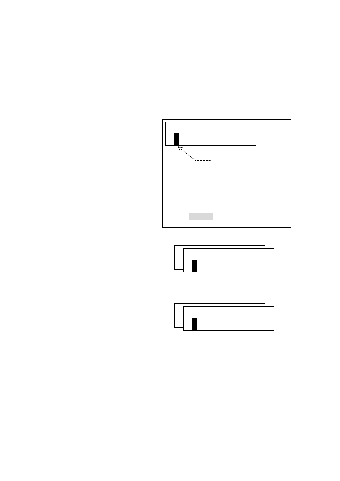
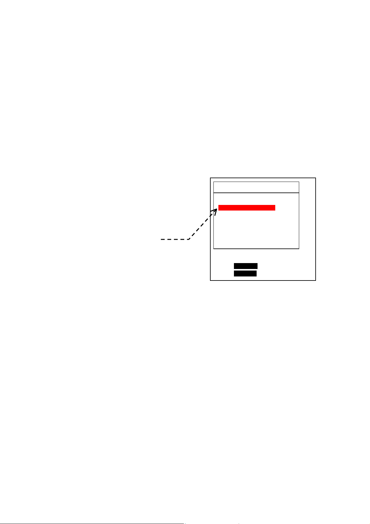
3.2. Setting a Password
It is assumed that a normal echogram screen is showing with no menu turned on.
Figure 3-1 Password Entry Window
① While holding down
beeps are heard, press both
and
password entry window should
then show up, as illustrated at
right.
simultaneously. A
② Enter the desired password
consisting of four (4) numerals, by
pressing the appropriate numeric
keys. Each character entered will
be replaced by an asterisk (
for security reasons.
An entry mistake can be erased
by pressing
Figure 3-2 Entering Password
③ Press
field should then change as
shown at right, asking you to
enter the same password again.
.
. The password entry
④ Re–enter the same password in
the same manner.
⑤ Press
If an incorrect password was entered at step
return.
. The window will then be turned off, allowing the echogram screen to return.
until two
*)
MENU NEW1 PASSWORD
[▲] = BS
PRESS I[PAGE]I TO EXIT ALL
MENU NEW1 PASSWORD
MENU NEW2 PASSWORD
*
MENU NEW1 PASSWORD
MENU NEW2 PASSWORD
*
****
Enter 4–digit passwor
starting here.
③, the first password entry field ( ①) will
to check
5
(continued on next page)
Page 14
Password Protecting the Menu Settings
CVR-010
3. Password–Protecting the Menu Settings (continued – 2/2)
3.3. Changing or Removing the Password
If you wish to change the current password or remove the password to allow free access to
the menu system, execute the following steps:
Figure 3-3 Password Initialization Window
① Display a password initialization
window by pressing both
simultaneously while holding
down
Figure 3-4 Changing/Removing Password Step – (1)
.
② Enter the current ( existing) pass–
word and then press
The password field will change as
shown at right.
Figure 3-5 Changing/Removing Password Step – (2)
③ Enter a new password if you wish
to change the current one, or
simply press
current password. The password
field will change as shown at right.
to remove the
④ Re–enter the new password and press
password). The password entry window will then be turned off.
This completes the menu password change/removal procedure.
.
and
MENU OLD PASSWORD
[▲] = BS
PRESS I[PAGE]I TO EXIT ALL
MENU NEW1 PASSWORD
MENU NEW1 PASSWORD
*
MENU NEW1 PASSWORD
MENU NEW2 PASSWORD
*
(or press one more time to remove the
Enter current password.
6
Page 15

Standard Components and Parts Supplied
CVR-010
4. Standard Components and Parts Supplied
The following components and parts are initially supplied as standard for each CVR–010
echo sounder, unless otherwise prearranged under a separate agreement with your dealer
or the manufacturer: Upon receipt of the package, check your delivery against the list below
and notify your dealer or the manufacturer immediately if any part is found missing.
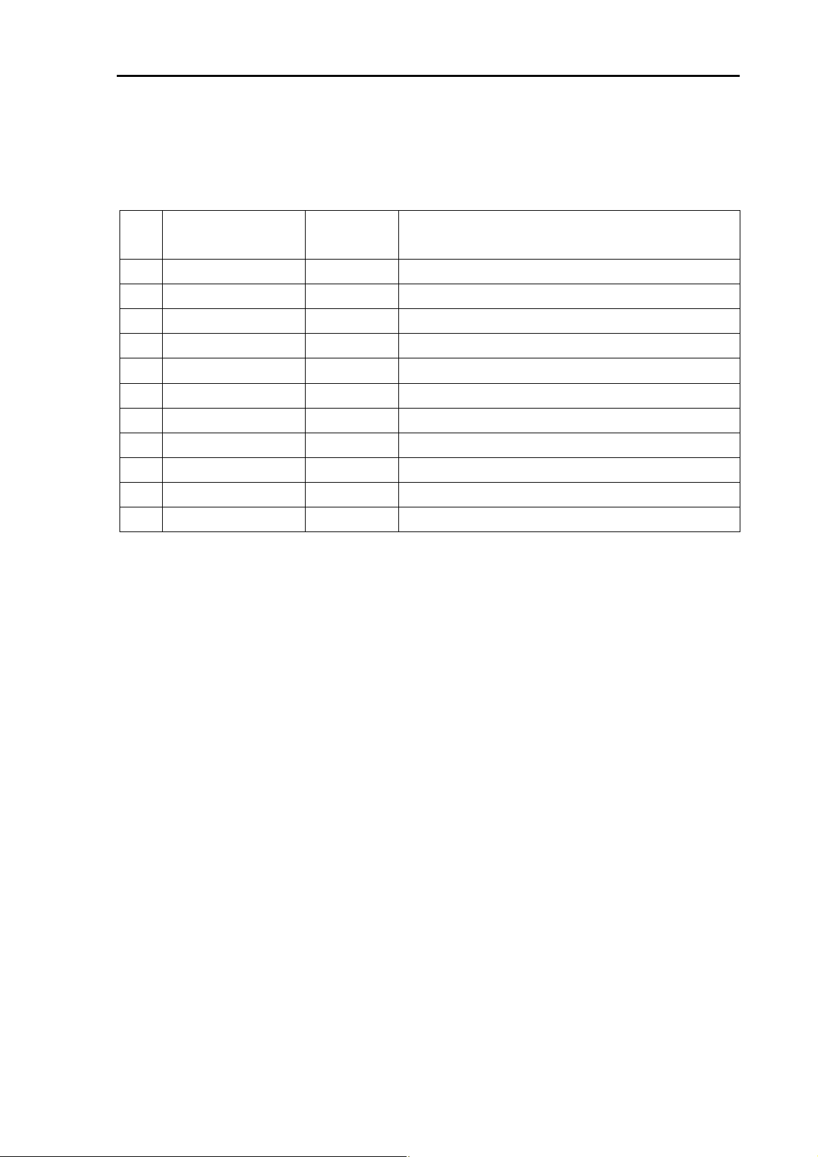
Table 4-1 List of Components and Parts Supplied as Standard
No. Name and Description Part No./Rating Q’ty
1 Echo sounder display unit CVR–010 1 pc
2 Mounting bracket SF–STD01 1 pc
3 Cabinet clamping knob
4 Power cable M402–PWR01/CW–272–3M 1 pc
5 Fuse (for 24V DC and up) 2A 2 pcs
6 Fuse (for 12V DC) 3A 2 pcs
7 2–pin plug (for ALARM ACK receptacle) CP111–2P 1 pc
2 pcs
8 6–pin plug (for ALARM OUT receptacle) CP111–6P 1 pc
9 8–pin plug (for I/O receptacle) CP111–8P 1 pc
10 3–pin plug (for TRANSDUCER receptacle) HS21P–3 1 pc
11 User’s manual (this manual) OPERATION MANUAL 1 copy
7
Page 16

Product Description
CVR-010
5. Product Description
The Model CVR–010 is a single–channel navigation echo sounder designed to comply fully
with IMO Resolution MSC.74( 69) Annex 4, and is type–approved by BSH on the basis of
compliance with the DIN EN ISO 9875 standards and pertinent IEC requirements for wheel
mark certification.
Featuring a 5.7–inch daylight–viewing, LED–backlit color TFT LCD screen, the equipment
displays the echogram using a total of seven user–definable ease–on–the–eye analog
strength–level colors that represent various layers of the bottom stratum. The display can be
set to show the bottom contour alone in a single color via a menu–guided procedure.
Digital depth readout is also available using easy–to–read large fonts with a clear on–screen
indication of the reference of measurement (from the waterline, the transducer or the keel),
and in meters, fathoms or feet. To comply with the IMO resolution, the depth reading must
be indicated in meters for navigational purposes.
With an optional GPS sensor plugged in or an onboard GPS data source connected, the
ship’s LAT/ LON coordinates, speed and heading data will also be displayed at the same
time.
A battery–backed realtime calendar clock is built in to indicate the date and time in UTC or in
the desired local time at all times. With an appropriate GPS sensor plugged in, the time is
automatically referenced to the atomic–precision GPS time.
Up to 12 hours of sounding data will be stored in non–volatile memory at approximately
two–second intervals, together with associated date and time, range in use plus position
coordinates (with an optional GPS sensor plugged in or a GPS source connected).
The user can review the stored data across any 15–minute segment at any point in time
over the past 12 hours through a specially designed window easily accessible with a
devoted key.
The depth sounding history can be graphically displayed to show how the depth varied over
the past hours. Detailed data is also available digitally via another window that can also be
accessed with a single keystroke.
The data can be output on demand in NMEA–0183 (IEC 61162 – 1 )–compatible format via
rear panel interface connectors for use in shore–based applications, and is protected
against a system reset.
An easy–to–use menu system is incorporated to set the transducer draft, depth reference,
echo threshold level, echo display mode, etc. in addition to operating parameters to be
selected mainly at installation time.
Unauthorized access to the menu system can be prevented with password entry, if desired.
For use with the CVR–010, high quality TOKIN 50 and 200 kHz transducers are
BSH–approved. A desired frequency should be specified at the time of ordering so that a
matched transceiver board is installed before shipping.
Both the receiver gain and TVG (anti–clutter) levels are automatically controlled for hands–
free operation when the equipment is operating in the fully automatic mode (AUTO). Manual
override of both functions is also possible. Interference from other echo sounders operating
in the vicinity can be effectively eliminated or reduced with a 3–step noise reduction
function.
The acquired data will also be output via the rear panel RS–422 connectors simultaneously
for use in other onboard applications requiring depth, date/time and position information.
The built–in alarms include depth alarm, bottom–missing alarm, power failure (low voltage)
alarm and power removal/shutoff alarm.
8
(continued on next page)
Page 17

Product Description
CVR-010
5. Product Description
(continued – 2/2 )
The depth alarm alerts the operator to decreasing depth ( shallow alarm). A variable depth
marker can be turned on to set the alarm depth graphically as well as digitally.
The bottom–missing alarm warns against the bottom echo being lost, becoming too weak or
exceeding the current range limit.
The power failure (low voltage) alarm will be activated if the power line voltage drops below
the factory–specified predetermined level.
The power removal/shutoff alarm will be triggered in the event power is accidentally
removed or shut off at the ship’s power source with the equipment operating, emitting
continuously a repeating beep for several minutes.
The alarm activation status, except for the power removal/shutoff alarm, will be indicated
both audibly and visually, and the alarm on/off switched outputs will be separately available
for driving externally connected alarm indicating devices through a devoted connector.
For use with onboard INS applications, the equipment outputs the NMEA–0183 (IEC
61162–1)–formatted alarm sentence for each alarm via one of the rear panel RS–422 ports
at specified intervals. When any of the alarms becomes active, the output’s status and
intervals will be changed accordingly, and an active alarm can be remotely acknowledged
and reset with an appropriate software command from an INS terminal or with a suitable
hardware on/off switch mounted at a different location.
The display cabinet has a rugged DC power supply built in that assures reliable operation
against a wide range of voltage fluctuations. In an installation where an AC power source is
available, the equipment can be operated primarily from the AC source through an optional
Model AC–2000 AC adapter for an automatic changeover to the DC power source in the
event of AC power outage.
9
Page 18

CVR-010
Specifications
6. Specifications
6.1. General Specifications
Display Screen: 5.7 inch 7–analog RGB-color LED–backlit TFT–LCD, QVGA
resolution, with backlighting level adjustable in 10 steps. LCD
module complies with IEC 62288 (Ed.1, 2008) standards.
Data Storage: Up to 12 hours of sounding data, depth range, associated
UTC date/time and
retained in flash memory protected from power shutoff or
system reset.
Data Retrieval: Stored sounding data (
of past 15 minutes, 1/3/6/12hours can be retrieved from flash
memory and can be graphically displayed in a devoted
soundings data history window, together with associated UTC
date/time, and
*
output in NMEA proprietary format on demand via
RS–422–A/B and I/O data connectors simultaneously.
Keypad Backlighting: Adjustable in 7 steps by front panel dimmer key
Cabinet
Size & Weight: 248/196(W)×216/196(H)×102(D) mm with/without mounting
bracket, 1.6 kg (cabinet) + 0.55 kg (mounting bracket)
Power Requirements: 11 – 40 VDC, 0.7A at 12V, 0.4A at 24V (typical)
Power consumption: approx. 10W
Ambient Temperature: –15 to +55
–40
Compass Safe Distance: 1.00m (standard compass), 0.55m (steering compass)
C (storage)
゚
C, 95% RH (operating, without condensation)
゚
1
*
Optional GPS sensor or GPS data source (NMEA–0183) required.
2
*
AC operation available with optional AC–2000 adapter connected
6.2. Echo Sounder Specifications
1
*
LAT/LON readouts are automatically
IEC 61162–1/NMEA–0183 DPT format)
1
LAT/LON coordinates. All stored data can be
Modes of Operation:
・ AUTO (default): Fully automatic selection and settings
(depth range, gain, TVG)
・ MANUAL: Manual selection and settings of above parameters
Depth Ranges (Maximum Range Limits):
A B C D E F G H
・ Meters (m,
default): 5 10 20 40 100 200 400 11800
・ Fathoms (FM): 2.5 15 15 20 40 100 200 400
・ Feet (FT ): 20 40 100 200 400 1000 2000 4000
Transducer Draft: Adjustable in 0.1–meter steps for each transducer.
10
(continued on next page)
Page 19

CVR-010
Specifications
6.2. Echo Sounder Specifications
(continued – 2/4)
Keel Offset: Adjustable in 0.1–meter steps for each transducer.
Transducer Frequencies (and BSH–Approved Matched Transducers):
・ 50 kHz (TOKIN TGM60–50–20L)
・ 200 kHz (TOKIN TGM80–200–20L)
Transmit Power: Approx. 600W
RMS max. to approved transducer
Transmit Pulse Lengths (
A B C D E F G H
in milliseconds):
・ Meters (m) : 0.14 0.3 0.6 1.1 2.7 5.4 5.4 5.4
・ Fathoms (FM): 0.14 0.3 0.6 1.1 2.7 5.4 5.4 5.4
・ Feet (FT): 0.14 0.3 0.6 1.1 2.7 5.4 5.4 5.4
Sounding Rates (
A B C D E F G H
per minute):
・ Meters (m) : 120 120 120 120 60 30 30 30
・ Fathoms (FM): 120 120 120 120 120 60 30 30
・ Feet (FT): 120 120 120 120 60 30 30 30
Velocity Standard: 1500.0 meters/second, fixed
Minimum Detectable Depth:
・ 50 kHz: 1 meter
・ 200 kHz: 50 centimeters
Accuracy of Measurement:
・ 20–meter range: Better than ±0.5 meters
・ 200–meter range: Better than ±5 meters
・ Other ranges: Better than ±2.5
% of digital depth readout
Range Discrimination:
・ 20 meter range: 5 mm/m
・ 200 meter range: 0.5 mm/m
chogram Presentation: The bottom echo is initially displayed in red only. It can be
E
displayed in up to 7 analog RGB colors through the menu
system, depending on strength, with red representing the
strongest echo level and blue, the weakest level (default
settings). Color–strength assignments can be user–defined.
Display Duration: The displayed echogram remains on screen for approximately
20 minutes.
Echogram Feed Rate: Once every 2 seconds, e.g. once every 4 soundings on range
below 40m, every 2 soundings on 100m range.
11
(continued on next page)
Page 20

CVR-010
Specifications
6.2. Echo Sounder Specifications
E
cho Dynamic Range: Change in echo indication to next stronger/weaker color
normally represents a 3–dB change in strength. Other
selectable dynamic ranges include 4, 5 and 6 dB.
Noise Reduction: 3 steps (low, mid and high), selectable via menu
Receiver Gain: Automatically adjusted for depth range in use; manually
adjustable in a total of 41 steps ( l evel 0 to level 40)
TVG (STC): Automatically adjusted for depth range in use; manually
adjustable in a total of 31 steps ( l evel 0 to level 30)
Audible and Visual Alarms:
The following alarms are available and enabled at all times, except for the
bottom–missing alarm:
● Depth: Warns against decreasing depth, with alarm triggering depth
user–presettable in 0.1–meter steps. Local alarm # 001
・ Audible: Beeps repeatedly at approximately 1–second intervals. The
sound can be muted by pressing
ACK command via one of the
・ Visual: Blinks repeatedly alarm symbol
value on red background at approximately 1–second intervals.
● Bottom–Missing: Warns if bottom echo is lost or too weak to measure depth, or
if depth exceeds the range limit, for 4 seconds or more.
Local alarm # 002, initially disabled
NOTE: To enable this alarm, see paragraph 8.12 for instructions.
(continued – 3/4)
or with an appropriate
RS–422 ports.
and on–screen preset
・ Audible: Beeps repeatedly at approximately 1–second intervals;
automatically muted in 5 seconds.
・ Visual: Blinks repeatedly on–screen depth readout unit (
FT) at approximately 1–second intervals.
● Power Failure: Warns against drop of power supply voltage below
factory–specified level (11.0 VDC). Local alarm # 003
・ Audible: Beeps repeatedly at approximately 1–second intervals. The
sound can be muted by pressing
ACK command via either of the RS–422 ports.
・ Visual: Blinks repeatedly alarm symbol
readout on red background at approximately 1–second
intervals.
● Power Removal/Shutoff: Warns against removal or shutoff of power source. (a udible
indication only, in the form of a beep occurring at approx.
1–second intervals for at least 5 minutes). The sound can be
silenced by pressing
12
.
or with an appropriate
and on–screen voltage
(continued on next page)
m, FM or
Page 21

CVR-010
Specifications
6.2. Echo Sounder Specifications
(continued – 4/4)
External I/O Interface Specifications
・
Online Data Outputs: IEC 61162–1/NMEA–0183–compatible data sentences
1
*
$SDDPT, $SDDBT, *2$PSKPDPT, $SDDBK) via all
(
rear–panel interface connectors ( RS–422–A/B and 8–pin I/O
data connectors) simultaneously.
With an optional GPS sensor plugged into the I/O data
connector, data sentences $GPGGA, $GPRMC and $GPZDA
will be appended to the above output strings. All sentences
can be separately turned on/off via the menu system.
1
*
output in meters only regardless of the depth readout unit in use
2
*
for use with SKIPPER IR 301 digital depth repeater
・ Output Interval: 1 second
Stored Data Output: IEC 61162–1/NMEA–0183–compatible proprietary format
・
3
*
$PJMCN) via all rear panel interface connectors
(
(RS–422–A/B and 8–pin I/O data connectors) simultaneously
3
*
Depth data will be output in meters only regardless of the depth readout unit
used in soundings.
Data Inputs: IEC 61162–1/NMEA–0183 sentences ( $GPGGA, $GPRMC,
・
GPVTG, $GPZDA) via rear–panel interface connectors
$
・ Alarm Outputs:
- Analog: 2 channels (for depth alarm and power failure/low voltage
alarm), by mechanical relay and solid–state relay via 6–pin
ALARM OUT connector
Mechanical Relay: Normally open pair of contacts for depth
alarm. Pins #3 and #4
Contact Ratings: 60V, 1A DC
Solid State Relay: Normally closed p air of cont acts for power
failure/low voltage alarm. Pins #1 and #2
Contact Ratings: 60V, 1A DC
Solid State Relay: Normally open pair of contacts for
acknowledgement output. Pins #5 and #6.
Contact Ratings: 60V, 1A DC
- Digital: Alarm sentence $SDALR via one of the RS–422–A/B
connectors for each of depth alarm (local alarm # 001),
bottom–missing alarm (local alarm # 002) and power
failure/low voltage alarm (local alarm # 003), compliant with
IEC 61162–1 format
-
Acknowledgement: Manually by pressing
or by shorting the two pins together
on the ALARM ACK connector with an external switch, or
remotely by entering NMEA–0183/IEC 61162–1 format
$__ACK command via one of the RS–422–A/B connectors.
NOTE: Specifications other than those stipulated in the pertinent IMO resolutions, IEC requirements or EN ISO 9875
standards are subject to change without notice or obligation.
13
Page 22
Basic Operating Instructions
A
*
1
CVR-010
7. Basic Operating Instructions
7.1. Interpreting Navigation Sounder Screen
The figure below illustrates a typical operating display showing a full–color bottom
topography. A brief description of on–screen readouts and objects is given in the following
pages.
Figure 7-1 Typical Full–Screen Full–Color Echogram Display
⑨ 1–Minute Time Calibrations
54゚31.314N
006゚52.717E
01/06/2010
06:35:47
② Color Scale
DFT= 0 . 0
iAUTO i
⑥ Control Mode
⑦ Transducer Draft
⑩ LAT/LON of
Present Position
⑪ Date & Time
① Bottom Echo
*
③ Depth Readout
GAIN=AT TVG =AT
NR=OFF
DBT10.5
11.9 m
BELOW
TRANSDUCER
⑭ Gain & TVG Levels,
⑬ Noise Reduction
Depth Alarm, set at 10.5m
⑫
T= automatic
④
m: meters
⑮ Transducer Location
Optional GPS sensor or GPS data source required.
⑧ Time Markers
0m
4m
1
8m
8m
12m
12m
16m
16m
20m
⑯ Zero Line
⑤ Depth Reference
Depth Readout Unit
14
(continued on next page)
Page 23
Basic Operating Instructions
CVR-010
7.1. Interpreting Navigation Sounder Screen
(continued – 2/5 )
① Bottom Echo
The bottom echo is shown in up to a total of seven different colors, depending on the
strength. The colors used to display the echoes are shown on the color scale (
②
) in
order of strength. Red, initially at the lower end of the scale, represents the strongest
part of the echo ( i.e. hardest layer of bottom stratum), and blue initially represents the
weakest part (i.e. softest layer of the bottom). It is possible to display only the contour
of the bottom in a single color via the menu–guided procedure. See paragraph 8.9 for
instructions.
② Color Scale
1
*
When the
echo display is set to show echoes in full colors, the colors used to display
various echo strength levels are listed here in order of relative strength. The color that
represents the strongest level is initially red, and the one that represents the weakest
level is initially blue. The intervening colors simulate various mid strength levels. See
paragraph 8.10.2 for related information.
An echo must be initially 3 decibels (dB) stronger or weaker than the adjace nt strength
level before it can be displayed in next stronger or weaker color. See paragraph 8.10.4
for greater details.
1
*
Paragraph 8.9, MAIN MENU → 8:ECHO DISPLAY → 2:NORMAL DISPLAY
Figure 7-2 Initial Assig nments of Echo Colors
Blue
Light Blue
Yellowish Green
Green
Yellow
Orange
Red
Strength Level 1 (weakest echo)
Strength Level 2
Strength Level 3
Strength Level 4
Strength Level 5
Strength Level 6
Strength Level 7 (strong est echo)
③ Depth Readout (1/2)
The depth to the bottom from the selected reference (⑤) is indicated here.
Readout Unit:
m=meters (initial setting), FM=fathoms, FT=feet
Refer to paragraph 8.10.3 for details.
< CAUTION >
To comply w ith IMO resolution MSC.74(69), measurements must be made in
meters for navigational purposes
.
To obtain a continuous readout, the bottom echo (① ) must be displayed in red, ora nge
or yellow (or three user–defined strongest echo colors). This is automatically
accomplished when you are operating the unit in the fully automatic control mode
(AUTO,
④
).
15
(continued on next page)
Page 24

Basic Operating Instructions
CVR-010
7.1. Interpreting Navigation Sounder Screen
(continue d – 3/5 )
③ Depth Readout (2/2)
If you are operating the unit in the manual control mode ( MANUAL, ④), adjust the
appropriate gain control accordingly. The TVG level may also have to be adjusted to
prevent surface clutters from disturbing depth reading. See paragraph
If the bottom echo is lost or too weak to measure depth continuous ly for 4 seconds or
more, ( or if the depth exceeds the current range limit continuously for 4 seconds or
more when in the manual control mode ), the bottom–missing alarm will be triggered,
blinking the current readout unit on a red background with digital readout turned off, and
emitting a beep at approx. 1–second intervals.
To rectify this situation, activate the manual control mode, and increase the receiver
gain or select a greater range. See paragraph 7.8.3 for details about the alarm function.
7.6.
④ Depth Readout Unit
The unit used in reading the current depth is indicated here.
・ m=meters (initial setting) ・ FM=fathoms ・ FT=feet
Refer to paragraph 8.10.3 for details. The stored soundings data will be in meters
regardless of the readout unit indicated.
< CAUTION >
To comply w ith IMO resolution MSC.74(69), measurements must be made in
meters for navigational purposes
.
⑤ Depth Reference
The reference to which measured depth is to be referred is indicated here.
・ BELOW TRANSDUCER: Depth referred to transducer (initial setting), DBT
・ BELOW SURFACE: Depth referred to surface (waterline), DBS
・ BELOW KEEL: Depth referred to ship’s keel, DBK
See paragraph 8.3 for details.
⑥ Control Mode (AUTO/MANUAL)
The control mode can be changed from/to AUTO/MANUAL by pressing
selected mode is indicated here.
・ AUTO =fully automatic control mode ・ MANUAL= manual control mode
. The
⑦ Transducer Draft (DFT= X.X)
The distance between the water surface and the transducer face, i.e. transducer draft,
is indicated. The draft can be entered directly by pressing
via the menu system (MAIN MENU → 1:TRANSDUCER DRAFT). See paragraph 8.2 for
details.
Figure 7-3 Time Marker Intervals – Example
, followed by
/, or
⑧ Time Markers
An orange marker and a yellow marker
alternately show up at 5–minute intervals on
any depth range, as in the example at right.
By counting the number of markers, you can check an approximate time period elapsed
across a particular horizontal segment on the echogram screen.
5 min. 5 min.
16
(continued on next page)
Page 25

Basic Operating Instructions
CVR-010
7.1. Interpreting Navigation Sounder Screen
(continued – 4/5 )
⑨ One–Minute Time Calibrations
These graduations are
displayed at one–minute
intervals, allowing you to
check the time passage to
one minute across a given
segment of the echogram.
Figure 7-4 One–Minute Time Calibrations
1 minute
⑩ LAT/LON of Present Position
When an optional GPS sensor is plugged into the rear panel I/O data connector or
when a position data signal from other GPS receiver is fed to that connector, the
equipment will display the latitude /longitude coordinates of your present position here
and will store the position data in non–volatile memory along with digital depth reading
and associated date/time data.
⑪ Date and Time
Date is shown in DD/MM/YYYY(month/ day/ year) format. Time is in 24–hour
HH:MM:SS ( hours: minutes: seconds) format, and is UTC unless a local time offset is
entered. See paragraphs 8.10.5 and 8.10.6 for date / time preset instructions. With an
optional GPS sensor plugged in, or a GPS data source connected, the time will be
automatically synchronized with the GPS time.
⑫ Depth Alarm
The alarm depth is indicated here. The abbreviation to the right of the
indicates the depth reference used in setting the alarm depth. See paragraph 8.3 for
more information on the reference.
・ DBT : depth below transducer (initial setting)
・ DBS: depth below surface
・ DBK: depth below keel
symbol
As soon as the current depth decreases beyond that value, the depth alarm will be
triggered. The alarm depth can be set via the following summarized steps. See
paragraph 7.8.3 for greater details.
(1) Turn on the Variable Range Marker (VRM) by pressing
(2) Repeatedly press
(3) Press
.
/ to place the VRM at the desired alarm depth.
.
⑬ Noise Reduction Level, NR = OFF/LOW/MID/HIGH
Echo sound ers operating nearby or other on board electronics can become a source of
interference. Noise reduction (NR) is the action of preventing such interfering signals
from cluttering the operating screen. The following NR levels can be selected via the
menu system
・ NR=LOW: Sets NR function at low reduction level.
・ NR=MID: Sets NR function at medium reduction level.
・ NR=HIGH: Sets NR function at high reduction level.
・ NR=OFF: Disables NR function. (initial setting)
* MAIN MENU → 4:NOISE REDUCTION
*:
17
(continued on next page)
Page 26

Basic Operating Instructions
CVR-010
7.1. Interpreting Navigation Sounder Screen
⑭ Gain and TVG Levels, GAIN=XX, TVG=XX
The receiver gain and TVG levels currently in use are indicated. When the equipment is
working in the automatic control (AUTO) mode, both indications read “AT.”
In the case of manual control ( MANUAL) mode of operation, the current levels are
numerically indicated (e.g. GAIN=18, TVG=30).
・ The receiver gain level can be manually changed by pressing
/ .
The indication GAIN is highlighted (GAIN ) during setting.
・ The TVG level can be manually changed by pressing
.
The indication TVG is highlighted (iTVG ) during setting.
⑮ Transducer Location
The relative location of the transducer is
See paragraph 8.10.7.2 for greater details.
Figure 7-5 Relative Location of Transducer
graphically indicated here.
(continued – 5/5 )
twice, followed by /
once, followed by
⑯ Zero Line
This (initially red) thick line is caused by a portion of transmitting energy leaking into the
receiver, and its upper edge represents the on–screen position of the transducer face.
When the transducer draft (
line shifts toward the bottom by the amount of the draft. See pa ragraph 8.2 for details on
draft entry. When the depth reference is set to “BELOW KEEL” with the correct keel
offset (
by the amount corresponding to the offset, and its display is suppressed intentionally.
See paragraph
distance from transducer to keel) entered, the zero line shifts above scale line 0
8.10.7.3 for details.
Aft
, depth from waterline to transducer) is entered, the zero
⑦
Middle
Fore
18
Page 27
Basic Operating Instructions
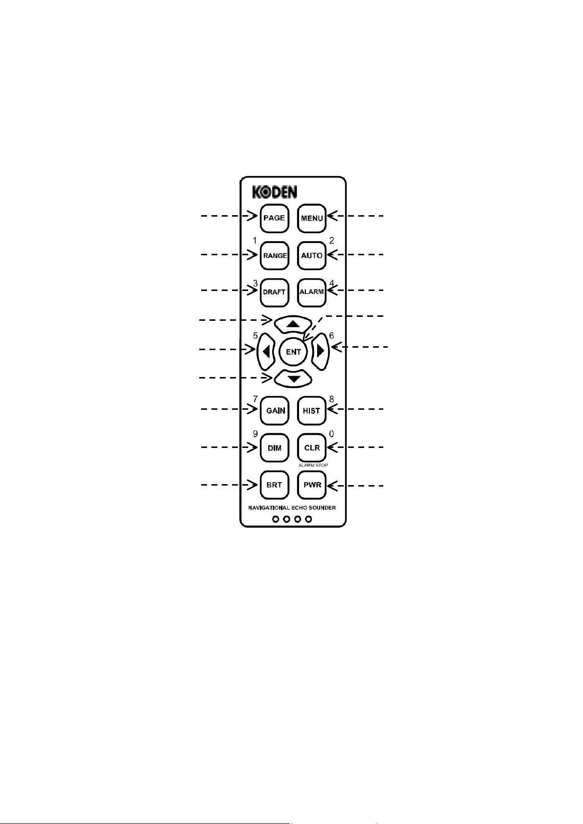
7.2. Control Panel Functions
The figure below shows the control panel of the equipment. A summary description of the
functions the keys and controls provide is given below and on the following pages.
Figure 7-6 Control Panel
① Page Key
・ Pressing this key opens a data log (LOG) window on the echogram screen to show
up to 17 pages of list of stored data including soundings and their associated dates
and times plus position coordinates (with a GPS sensor plugged in). Each page
carries a total of 9 sets of data. To turn the page forward, press
backward, press. See paragraph 7.7.4 for details.
①
②
③
④
⑤
⑥
⑦
⑧
⑨
⑩
⑪
⑫
⑬
⑭
⑮
⑯
⑰
CVR-010
. To turn it
A second keypress closes the window.
・ When a menu or a number of menus are currently open, pressing this key will close
all menus at a time, returning you to the normal echogram screen.
・ Turning the equipment on while holding down this key opens a SYSTEM MENU,
enabling you to select echogram background colors, perform a self–diagnostic test,
output stored data to a PC, select menu languages, and set the optimum TVG
response depending on the transducer installed. See paragraph 9.1 for details.
19
(continued on next page)
Page 28
Basic Operating Instructions
CVR-010
7.2. Control Panel Functions
② Depth Range Key
・ Pressing this key activates the function of
depth range selection, highlighting the lower
range limit calibration, like the example at
right.
. ・ To select a desired range, press
greater ranges) or
・ When a menu is open, this key acts as
numeric key “1” to enter value 1 or to
select menu option 1.
Figure 7-7 Indication of Activating Range Selection Function – Example
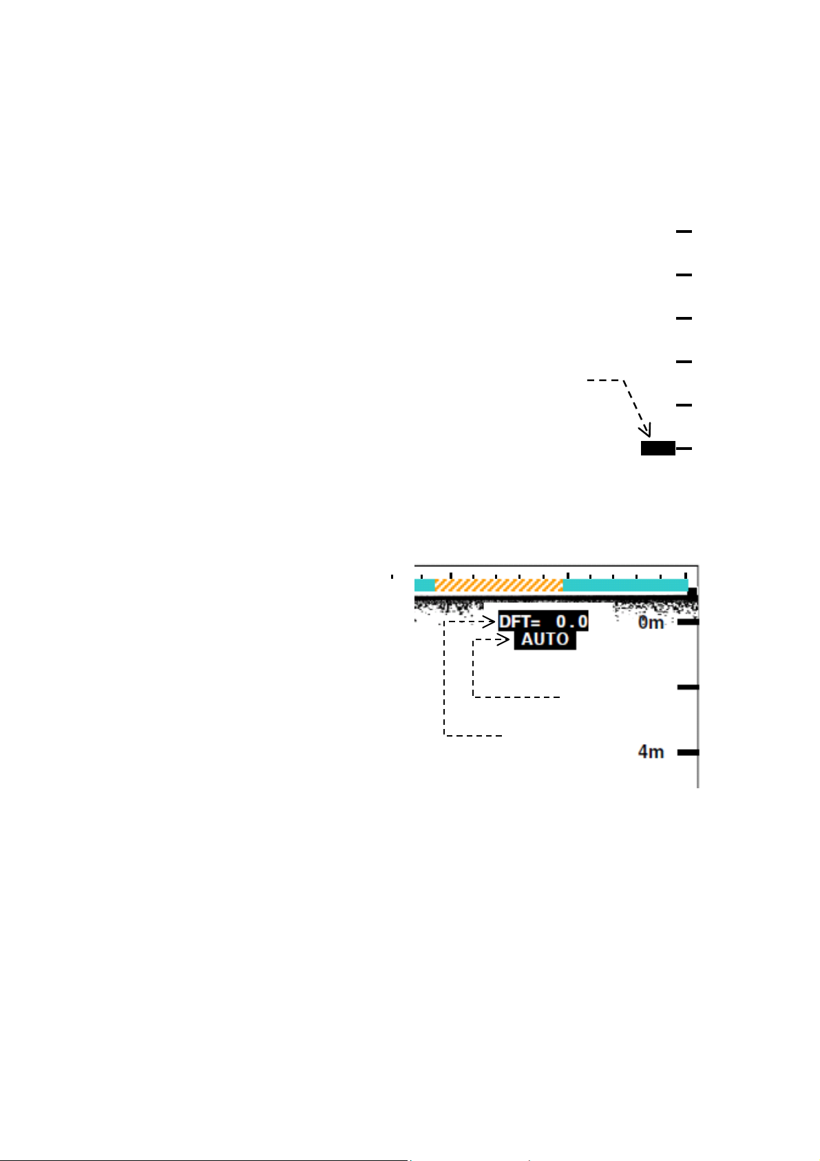
③ Transducer Draft Key
To read depth from the surface or from the keel, the appropriate transducer draft value
(i.e. the distance between the waterline and the transducer face) has to be entered. The
draft is initially set at 0.0 meter (DFT= 0.0).
Figure 7-8 On–Screen Operating Parameter Indications – Example
・ Pressing this key activates the
function of entering the transducer
draft. The legend “ DFT= 0.0” just
below the upper screen edge will
be highlighted, like the example at
right.
(continued – 2/7)
(for smaller ranges).
(for
Range selection
function activated
12m
16m
i20m
To enter the draft, press
To exit the mode, press
・ When a menu is being opened,
this key acts as numeric key “3” to
enter value 3 or to select menu
option 3.
④ Up Key
・ On normal echogram screen with no menu opened, pressing this key will result in an
operational error, causing the unit to beep three times in quick succession.
・ When the variable range marker (VRM) is turned on, pressing this key moves the
marker upward (i.e. in the shallowing direction).
・ When a menu with two or more options is being opened, pressing this key selects
those options downward.
To finalize selection, press
・ When selecting the depth ranges (②), pressing this key selects smaller ranges.
/.
again.
Control Mode
Transducer Draft
.
20
(continued on next page)
Page 29
Basic Operating Instructions
CVR-010
7.2. Control Panel Functions
⑤ Left Key
・ On normal echogram screen, pressing this key will result in an operational error,
causing the unit to beep three times in quick succession.
・ When a menu is being opened, this key acts as numeric key “5” to enter value 5 or
to select menu option 5.
・ When the soundings history window (HISTORY) is being opened (with
pressing this key moves the vertical line cursor to the left on the time passage scale,
showing the depth registered at the date and time (and the
shown just below the scale.
1
*
source plugged into the rear–panel
⑥ Down Key
・ On normal echogram screen with no menu opened, pressing this key will result in an
operational error, causing the unit to beep three times in quick succession.
・ When the variable range marker (VRM) is turned on, pressing this key moves the
marker downward (i.e. in the deepening direction).
・ When a menu with two or more options is being opened, pressing this key selects
those options downward. To finalize selection, press
・ When selecting the depth ranges (②), pressing this key selects larger ranges.
LAT / LON information is available with an optional GPS sensor or IEC 61162–1–compatible GPS data
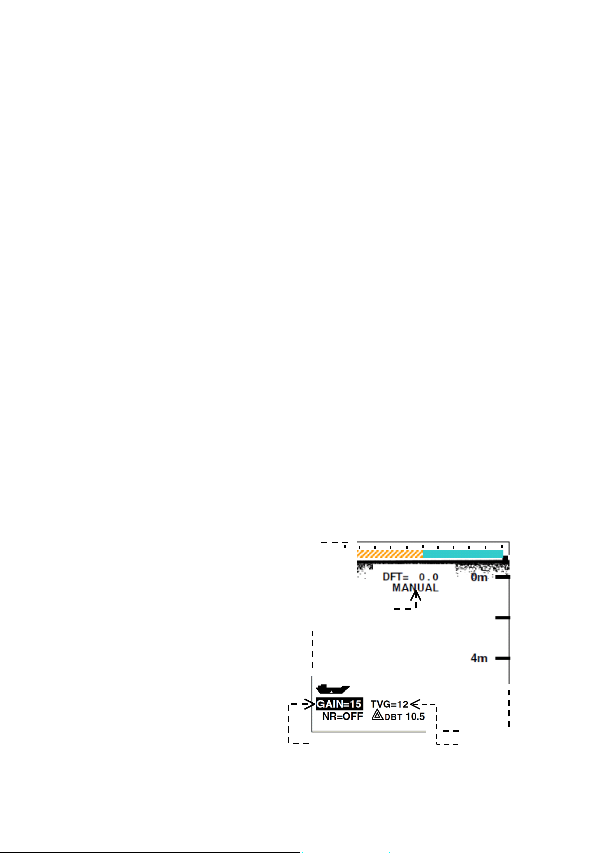
⑦ Receiver Gain/TVG Key
・ When the equipment is operating in t he automatic control (AUTO) mode, pressing
this key once changes the control mode to “ MANUAL, ” and highlights gain level
indication “GAIN=XX” as in the example below. You can then adjust the receiver
gain level manually by pressing
illustrated below.
To return to “AUTO,” press
Figure 7-9 Parameter Indication in Manual Control Mode – Example
・ Pressing the key twice highlights
TVG level indication “TVG=XX,”
allowing you to set the TVG (initial
gain suppression) using
・ When a menu is being opened,
this key acts as numeric key “ 7” to
enter value 7 or to select menu
option 7.
(continued – 3/7)
I/O data connector.
/. The gain level is numerically shown as
.
/.
Control Mode
1
*
LAT/LON coordinates)
.
),
Receiver Gain Level
21
TVG Level
(continued on next page)
Page 30
Basic Operating Instructions
CVR-010
7.2. Control Panel Functions
⑧ Dimmer Key
(continued – 4/7)
・ Pressing this key changes the backlighting level of the keypad in a total of 6 steps.
After the lowest level is reached, further keypress returns you to the highest level.
・ When a menu is being opened, this key acts as numeric key “ 9” to enter value 9 or
to select menu option 9.
⑨ Brightness Key
Pressing this key adjusts the screen brightness level in a total of 6 steps to suit the
ambient lighting condition.
⑩ Menu Key
Figure 7-10 MAIN MENU
A first keypress activates the menu system,
opening a main menu (MAIN MENU), as
illustrated at right. A second keypress turns
it off. The menu system allows you to make
various settings that suit your operational
requirements. Detailed instructions are
given in section 8 (Advanced Settings).
Option selected
(highlighted in red b ackground)
Menu options can be selected by pressing
appropriate numeric keys. The one that is
currently selected is shown highlighted in a
red background.
MAIN MENU
1:TRANSDUCER DRAFT
2:DEPTH REFERENCE
3:ECHO THRESHOLD
4:NOISE REDUCTION
5: WHITE LINE
6:HISTORY SCALE
7:SIMULATION
8:ECHO DISPLAY
9:INSTALLATION SETTINGS
PRESS i [MENU] TO PREVIOUS MENU
PRESS i [PAGE] TO EXIT ALL
● 1:TRANSDUCER DRAFT: Enters transducer draft.
● 2:DEPTH REFERENCE: Selects references to which measured depth is to be
referred (i.e., waterline, transducer face or keel).
● 3:ECHO THRESHOLD: Selects weak echo suppression levels.
● 4:NOISE REDUCTION: Selects noise reduction levels.
● 5: WHITE LINE: Selects while line gain levels.
● 6:HISTORY SCALE: Selects time scales when playing back stored data.
● 7:SIMULATION: Turns on/off built–in echo sounder simulator.
● 8:ECHO DISPLAY: Selects single color bottom contour only or full color
echoes for display
● 9:INSTALLATION SET TINGS: Opens a submenu with the following options:
.
・1:ECHO COLORS: Assigns desired colors to echo strength levels.
・2:DEPTH UNIT : Selects metric (m), fathom (FM) or footage (FT)
readout unit.
・3:DYNAMIC RANGE: Selects echo dynamic ranges.
・4:UTC/LST (offset): Selects UTC or local standard time (LST).
・5:CLOCK PRESET: Presets built–in clock and calendar.
・6:TRANSDUCER SETTINGS: Registers transducer location or keel offset.
・7:DATA OUTPUT PORT : Selects data outputs for use by external devices.
・8:BOTTOM MISSING ALM: Enables/disables bottom–missing alarm.
・9:DEPTH READOUT RESPONSE: Selects appropriate time periods for holding last valid
depth data in bottom–missing condition to avoid
frequent bottom searching operation.
・0:KEY BEEP SETTING: Turns on/off keypre ss beep.
22
(continued on next page)
Page 31

Basic Operating Instructions
A
CVR-010
7.2. Control Panel Functions
(continued – 5/7)
⑪ Auto/Manual Control Mode Key
・ Pressing this key selects the two control modes: AUTO and MANUAL. The
equipment is initially placed in the AUTO mode, selecting depth ranges and
adjusting receiver gain and TVG levels automatically so that the bottom echo is
always displayed in the lower half of the screen.
The illustrations below show an example of the on–screen parameters that indicate
which mode the unit is currently operating in.
Figure 7-11 Parameter Indications in AUTO and MANUAL Control Modes – Example
AUTO Control Mode
MANUAL Control Mode
uto Mode
Manual Mode
Gain and TVG levels automatically adjusted
Gain and TVG Levels manually adjusted
・ A first keypress changes the control mode to “MANUAL,” allowing manual selection
of depth ranges and manual setting of the gain/TVG level. See paragraphs
② and
⑦ for the relevant summarized instructions.
< CAUTION >
When in the manual mode, the receiver gain must b e adjusted so that
the bottom echo is displayed in red, orange or yellow (or one of the
three strongest echo colors, if you have changed the color
assignments) for successful digital depth reading.
・ If you change the gain or TVG level while in the AUTO mode, the unit will be placed
in the MANUAL mode. See paragraph
・ A second keypress changes the control back to “AUTO.”
・ When a menu is being opened, this key acts as numeric key “2” to enter value 2 or
to select menu option 2.
⑦ for related information.
23
(continued on next page)
Page 32

Basic Operating Instructions
A
CVR-010
7.2. Control Panel Functions
⑫ Alarm/VRM Key
・ Pressing the key once turns on the VRM
(variable range marker), a horizontal
dotted line with its current position
readout, as in the example at right.
A second keypress turns it off.
The VRM is used to set the depth for the
depth alarm, and can be shifted upward/
downward by pressing
Pressing
VRM position.
・ When a menu is being opened, this key
⑬ Enter Key
・ On normal echogram screen
1
*
Alarm depth below transducer (DBT)
acts as numeric key “ 4” to enter valu e 4
or to select menu option 4.
with no menu opened or
without VRM (⑫) on–screen,
pressing this key will result in
an operational error, causing
the unit to beep three times in
quick succession.
sets the alarm depth at the
(continued – 6/7)
/ .
Figure 7-12 Variable Range Marker – Example
GAIN=AT TVG=AT
NR=OFF
DBT 15.7
15.7
VRM placed at 15.7m
10m
20m
30m
40m
larm depth at 15.7m*
1
・ When the VRM is currently showing, pressing this key sets the alarm depth at that
position and activates the depth alarm.
・ When you are making a setting or selecting menu options, pressing the key
completes that setting or finalizes the selection of that option.
⑭ Right Key
・ On normal echogram screen, pressing this key will result in an operational error,
causing the unit to beep three times in quick succession.
・ When a menu is being opened, this key acts as numeric key “6” to enter value 6 or
to select menu option 6.
・ When the soundings history window ( HISTORY) is being opened (with
pressing this key moves the vertical line cursor to the right on the time passage
scale, showing the depth registered at the date and time (and the
coordinates) shown just below the scale.
2
*
LAT / LON information is available with an optional GPS sensor or IEC 61162–1–compatible GPS data
source plugged into the rear–panel
,⑮ ),
2
*
LA T/LON
I/O data connector.
24
(continued on next page)
Page 33

Basic Operating Instructions
*
1
r
CVR-010
7.2. Control Panel Functions
⑮ Soundings History Key
・ Pressing this key opens a
soundings history (HISTORY)
window in the left half screen, as in
the example at right, in which the
history of depth soundings over the
past 12 hours is shown graphically.
The various types of data at the
line cursor position are shown in
the bottom section of the window,
as in the example. The cursor can
be moved by pressing
To close the window, press
again or
*
The time span, 15 minutes in the above example, can be changed by pressing
・ When a menu is being opened, this key acts as numeric key “8” to enter value 8 or
1
Optional GPS sensor or GPS data source
required
.
. The following values are selectable: 5 minutes, 15 minutes, 30 minutes,1 hour,
2 hours, 3 hours, 6 hours and 12 hours. Refer to paragraph 7.7 for greater details.
to select menu option 8.
.
Date, time,
coordinates, depth, draft,
keel offset, depth range
in use, at Line Curso
position
⑯ Clear/Alarm Stop Key
・ This key is used to silence the currently active audible alarm(s), including the power
removal/shutdown alarm that will be triggered by unplugging the power cable or by
switching the power off at the source.
・ Pressing the key acknowledges and resets the currently triggered alarm in the same
manner as sending an ACK command from an INS device through the rear panel
interface connector RS–422–A/B. Refer to paragraph 13.3.4 for greater details.
NOTE: The pair of pins #5 and #6 on the ALARM OUT connector will also be closed for 3 seconds.
・ When a menu is being opened, this key acts as numeric key “9” to enter value 9 or
to select menu option 9.
⑰ Power Key
This key turns on/off the equipment. To turn it off, press and hold down the key for a few
seconds (until you hear a series of beeps – two slow beeps followed by two quick
beeps). This delayed action is intentional to prevent an accidental shutoff.
Do not turn the unit off by removing the power cable or shutting off the power source.
(continued – 7/7)
/
.
LAT/LON
Figure 7-13 Soundings History Window – Example
< CAUTION >
/
25
Page 34

7.3. Selecting Depth Ranges
7.3.1. Manual Selection
Basic Operating Instructions
CVR-010
A total of eight depth ranges are available in meters (m), fathoms (
illustrated below, and are automatically selected to display the bottom echo and read depth
when the unit is working in the automatic control ( AUTO) mode. In applications where you
wish to monitor depth on a certain fixed range scale or where you wish to select range
scales manually, press
in paragraph 7.2) and the desired range can be selected by pressing the following pair of
keys:
・
・
All depth ranges start at scale line zero (0), unless a
entered. Select depth ranges so that the bottom echo is displayed, preferably within the
lower half part of the screen for ease of monitoring the changing depth graphically. If the
depth exceeds the current range limit, a bottom–missing alarm will be triggered. See
paragraph 7.8.4
*
to selects smaller ranges ( in H–to–A direction).
to selects larger ranges ( in A–to–H direction).
for details.
1
Paragraph 8.2 *2Paragraph 8.10.7.3.
first. The control mode will then be switched to “ MANUAL,” (②
1
*
transducer draft or *2keel offset is
Figure 7-14 Depth Range Arrangement
FM) or feet (FT), as
26
Page 35

Basic Operating Instructions
A
7. 3. 2. Automatic Selection (Automati c Mode of Operation)
CVR-010
The equipment is initially in the automatic control (AUTO) mode, selecting depth ranges,
1
*
adjusting the receiver gain and
TVG levels (shallow gain suppression level) – all
automatically. The bottom echo will always be displayed in the lower half screen area
regardless of changes in depth.
Pressing
will switch the control to the manual mode (MANUAL). A second keypress will
switch it back to “AUTO.”
The figure below illustrates an example of how depth range selection occurs with this mode
activated, as you travel over a gradually deepening bottom. As soon as the bottom shows up
at the lower end of the scale lines on the current depth range, the next greater range will be
automatically selected. When traveling over a gradually shallowing bottom, the range
selection sequence is reversed. As soon as the bottom is registered in the upper half screen,
the next smaller range will be switched in.
1
TVG: Time–varied gain. This function, which sharply reduces the receiver gain at the start of each sounding and
*
gradually recovers the normal gain level with time, is used to prevent surface clutters and other noise–producing
reflections near the surface from disturbing depth measuring operation.
Figure 7-15 Automatic Dept h Range Selection – Example
Range D Range C Range B Range A
On–screen status indication “AUTO” will be turned on highlighted as in the example below
to indicate that the unit is currently operating in the automatic control mode.
Figure 7-16 On–Screen Indication of Automatic Control Mode
utomatic control mode
27
Page 36

Basic Operating Instructions
CVR-010
7.4. Interpreting Echo Display
7.4.1. Bottom Echo in Full Colors
The equipment normally shows only the strongest part of the bottom echo in a single color
(initially red).
Echoes including the bottom reflection can however be displayed in up to a total of seven
different colors – initially, red, orange, yellow, green, yellowish green, light blue and blue,
which represent the various layers of the bottom stratum in order of strength – via the
1
*
procedure given in paragraph 8.9; namely, red represents the strongest level, and blue,
the weakest one.
A colored bar (termed “ color scale” in this manual) located at the left end of the screen
indicates the colors that are currently assigned to display echoes, as in the illustration below.
1
*
MAIN MENU→8:ECHO DISPL AY→ 2:NORMAL DISPLAY
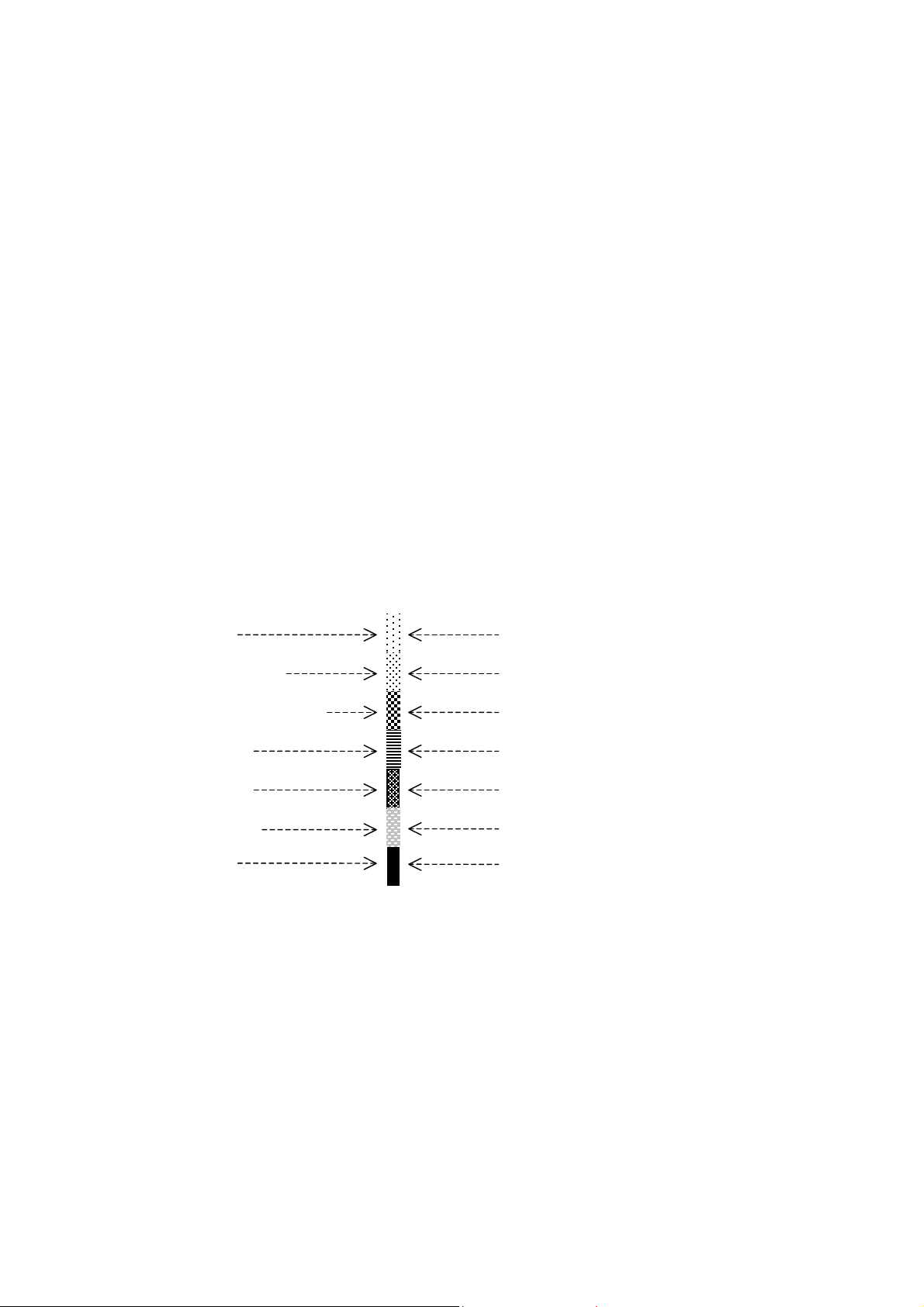
Figure 7-17 Initial Assignments of Bottom Echo Colors
Initial Color Assignments
Blue (weakest)
Light Blue
Yellowish Green
Green
Yellow
Orange
Red (strongest)
Figure 7-18 Initial Echo Dynamic Range
You can change those color assignments by
selecting from a total of 10 different colors provided.
See paragraph 8.10.2 for instructions.
There is initially an approximately 3 dB difference in
strength between two adjacent colors, as illustrated
in the figure at right, meaning that a particular color is
approx. 1.4 times stronger or weaker than either
adjacent color. This difference, called the echo
dynamic range, can be changed to suit various
bottom conditions (hard, soft, muddy, etc.). See
paragraph 8.10.4 for instructions.
Bottom Echo
3 dB
3 dB
3 dB
3 dB
3 dB
3 dB
28
Page 37

Basic Operating Instructions
CVR-010
7.4.2. Multiple Bottom Echoes
When navigating a shallow water area, you may observe a bottom–like echo at twice the
present depth, and sometimes also at three or four times the depth. This multiple echo
phenomenon occurs when the first echo is reflected back and forth a number of times
between the water surface and the bottom like reverberations.
In the case of the example below, a first reflection, which is used to register the depth, is
bounced back to the bottom, and then back again to the transducer as a second reflection,
thereby causing that echo to be recorded at twice the depth.
The appearance of multiple bottom echoes indicates that the bottom is relatively hard.
Figure 7-19 Display of Multiple Bottom Echoes – Example
1st Reflection
10
2nd Reflection
The effect of multiple reflections may be reduced by decreasing the receiver gain (through
gain and / or TVG adjustment, paragraphs 7.5 and 7.6) when you are operating the unit in
1
*
manual control (MANUAL) mode. Occasionally a large school of fish or a temperature
the
layer can also cause the equipment to lock onto it, thus producing an incorrect digital depth
readout.
1
Pressing
*
control
( AUTO) mode, attempting to change the receiver gain or TVG level also changes the mode to “ MANUAL.”
switches the control between automatic mode and manual mode. When the unit is in the automatic
20
Whenever you have any doubt about the validity of digital depth reading, check the depth
graphically against the on–screen scale calibrations to determine whether the current digital
readout is valid or not.
A special caution should be exercised when using digital depth information
while in shallow water operation because the second echo may be tracked for
depth measurement, resulting in a digital readout twice the actual depth.
29
Page 38

Basic Operating Instructions
A
CVR-010
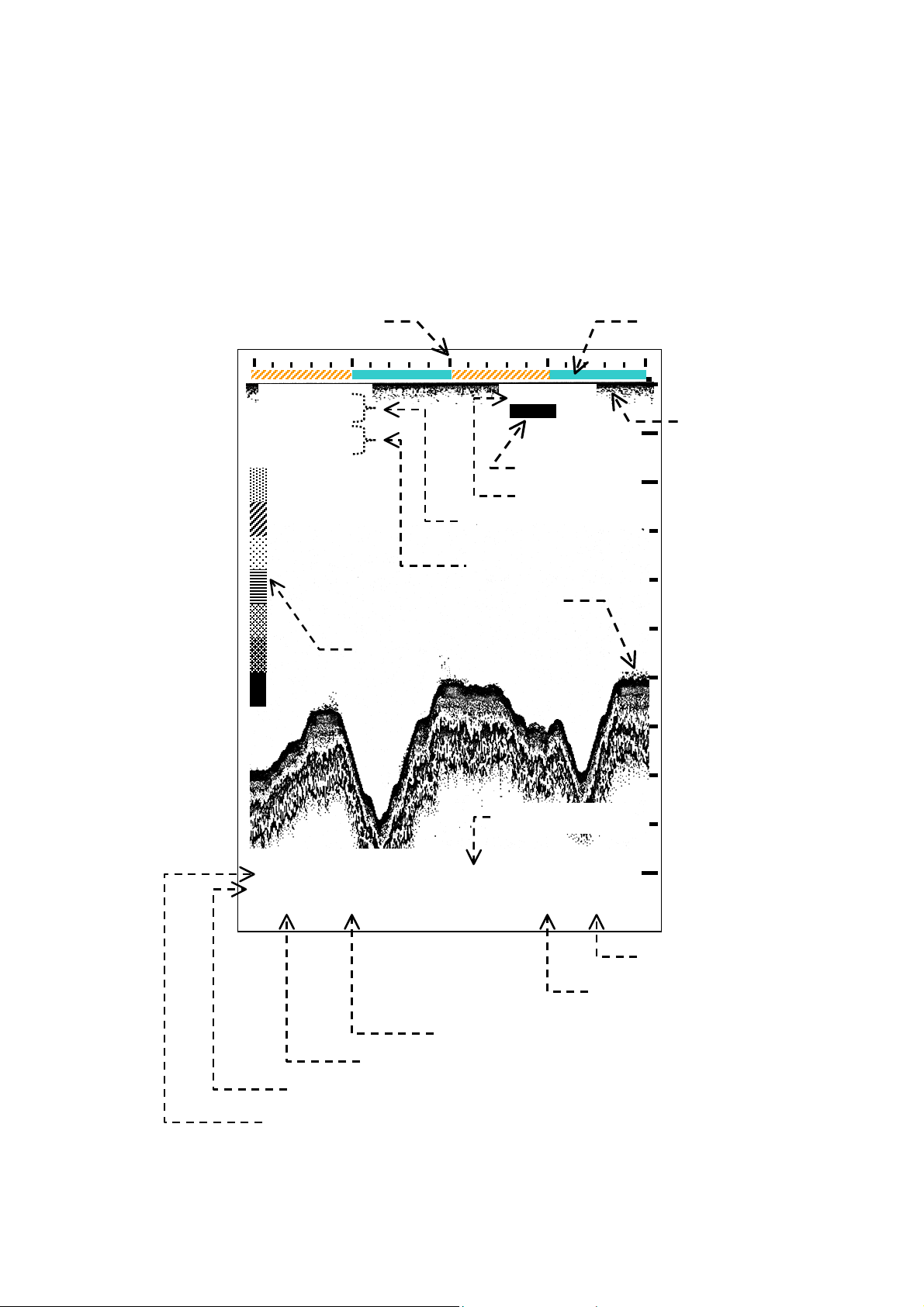
7.4.3. Other Echoes
1
*
When the
2
*
echoes from fish schools, temperature layers, and various tiny objects, like plankton
echo display is set to show echoes in full colors, the equipment will show
concentrations and air bubbles, in addition to the bottom echo. The figure below is an
example of how such echoes show up on the screen. A thick line appearing in the strongest
echo color at the upper edge of the echo display area is called a zero line, which is caused
by a portion of transmitted energy leaking into the receiver, and represents the on–screen
position of the transducer. When a transducer draft is entered ( paragraph 8.2 ), the zero
line shifts down from the top scale calibration ( scale 0) by the amount of the draft. When a
keel offset is entered (paragraph 8.10.7.3), the zero line occurs above scale 0, and its
display is suppressed.
1
*
Paragraph 8.9. (MAIN MENU→8:ECHO DISPLAY→2:NORMAL DISPLAY)
2
*
Those echoes are mostly suppressed by TVG with the unit in the automatic control mode.
Figure 7-20 Typical Display of Shallow Water Echoes
Zero Line
ir bubbles, plankton, etc.
Fish Schools
Fish Schools
Bottom
Current depth (14.8m in this example)
14.8m
BELOW
TRANSDUCER
< WARNINGS >
1. A LARGE FISH SCHOOL, ESPECIALLY ONE AT SHALLOW DEPTHS, CAN
OCCASIONALLY PRODUCE AN EXTREMELY STRONG ECHO, CAUSING THE
EQUIPMENT TO LOCK ONTO THAT ECHO AS THE BOTTOM. AN INCORRECT
DIGITAL READOUT WILL OCCUR AS A RESULT. BE SURE TO CONFIRM THE
READOUT BY COMPARING IT WITH ON–SCREEN BOTTOM ECHO LOCATION. TOTAL
RELIANCE ON THE DIGITAL DISPLAY IS DANGEROUS AND MUST BE AVOIDED,
ESPECIALLY WHEN TRAVELING IN SHALLOW AREAS.
2. WHEN TRAVELING OVER A SHALLOW BOTTOM, THE EQUIPMENT MAY
OCCASIONALLY LOCK ONTO THE SECOND BOTTOM ECHO, READING TWICE THE
ACTUAL DEPTH. BE SURE TO COMPARE THE BOTTOM ECHO POSITION WITH THE
DIGITAL DEPTH READOUT WHENEVER NAVIGATING SHALLOW WATER AREAS OR
WHENEVER THE DIGITAL REA DOU T IS QUE STI ONA BLE .
8.6 for related information.
See paragraphs 7.4.2 and
30
Page 39

Basic Operating Instructions
7.5. Adjusting Receiver Gain Level Manually
The appropriate receiver gain level is automatically maintained while the unit is operating in
the automatic control (AUTO)mode. In situations where greater gain is required for stable
depth reading operation, use the following steps:
① Press
will be indicated as in the example below.
② Repeatedly press
satisfactory results are obtained. Too high gain
may, however, result in cluttering the screen,
especially near the surface, leading to unstable
operation. Pressing
③ The *TVG level ( shallow gain suppression level )
may also have to be raised to prevent surface
clutters from disturbing depth reading.
7.6 for details
once to activate the manual control (MANUAL) mode. The current gain level
Figure 7-21 Parameter Indication for Manual Gain Adjustment – Example
to increase the gain until
decreases the level.
Manual Control
*Paragraph
.
CVR-010
To return to the AUTO mode, press
Lack of receiver gain will cause the bottom–missing
alarm to be triggered. See paragraph 7.8.4 for
information on the alarm.
7.6. Adjusting TVG Level Manually
TVG stands for time–varied gain, and is designed to sharply drop the receiver gain at the
start of each transmission, and then gradually recover the normal gain level as the
transmitted signal travels deeper toward the bottom. When the equipment is operating in the
automatic control (AUTO) mode (initial setting), TVG is also automatically adjusted.
Figure 7-22 Adjusting TVG Level – Example
Surface clutters ( plankton,
In situations where it is necessary to
air bubbles and other small
particles in suspension)
(a) Reflections near transducer face with no TVG effect
=
.
Current gain level
(b) with maximum TVG effect
TVG=30
control the receiver gain manually to
show the bottom in strong colors, for
instance when traveling over a soft
bottom giving a weak echo while in
automatic mode of operation, you will also
have to adjust the TVG level manually to
reduce the effect of surface clutters for
stable depth reading.
31
(continued on next page)
Page 40

Basic Operating Instructions
CVR-010
7.6. Adjusting TVG Level Manually
With the TVG set at its maximum level during shallow depth operation,
extremely weak bottom echo may result, triggering the bottom–missing
alarm.
Figure 7-23 Parameter Indication for Manual TVG Adjustment – Example
① Press
(MANUAL) mode. The TVG level indication will
then be highlighted as in the example at right.
twice to activate the manual control
(continued – 2/2)
< CAUTION >
② You can now select up to 31 TVG levels (TVG=0,
minimum to TVG=30, maximum) by pressing
. Repeatedly press
level until satisfactory results are obtained. Too
high level at shallow depths may, however,
weaken the bottom echo as well, leading to
unstable depth reading operation.
Pressing
decreases the suppression level.
③ To return to the AUTO mode, press
to increase the TVG
.
/
Current TVG level
Manual Control
32
Page 41

7.7. Retrieving Soundings Data History
7.7.1. Introduction
Basic Operating Instructions
CVR-010
The equipment automatically stores depth, UTC date and time, maximum depth range
used, and
instructions enable the user to retrieve such data via an on–screen graphical user interface
called the “HISTORY” window.
1
*
position data for a 12–hour period at intervals of two seconds. The following
*1: LAT / LON coordinates data will be stored when an appropriate GPS sensor is plugged into the rear panel I/O
d a t a connector.
7.7.2. Displaying History Window
To display the HISTORY window, simply press
display, as in the example below. A
the keys can be normally used to perform their assigned functions while the window is being
opened.
2
*
Pressing also closes the window.
A close–up view of a typical window is given in Figure 7–25. Data registered over the time
scales of past 5 minutes,15 minutes, 30 minutes,1 hour, 2 hours, 3 hours, 6 hours and 12
hours can be retrieved.
The history of depth soundings will be displayed graphically relative to the above time scales
as well as digitally via the procedures detailed in the following paragraphs.
Once shown in the window, the data will not be automatically updated, though the current
data will be continuously stored in memory. To update the data in the window, close the
window first by pressing
. It will show up over the echogram
2
*
second keypress turns the window off. The rest of
Figure 7-24 Echo Sounder Screen with HISTORY Window Opened – Example
(or
) and then open it again by pressing
HISTORY window
.
33
Page 42

Basic Operating Instructions
*
1
)
4
,
A
CVR-010
7.7.3. Retrieving Data Registered at Specific Date/Time
An example soundings data history window is illustrated below where the vertical axis
represents the depth scale and the horizontal axis, the time passage. The history of
soundings over the past 12 hours is displayed graphically , while the rest of the data stored at
the line cursor position are digitally shown at the bottom of the window, as in the example.
IMPORTANT
If, for any reason, the equipment was switched off before current operation, all previous data
saved until that moment will be displayed in blue, while the data collected during the current
operation will be in white, indicating that discontinuity in time exists in the data being
displayed.
To change the time passage scale, press
the upper edge of the window, as in the example.
or. The current scale is shown just above
Figure 7-25 Soundings Data History Window – Example
Time passage scale
Can be changed by pressing
or
.
HISTORY(12 HOURS
DBT
m
0
4
8
12
16
Line Cursor
Can be shifted to the left/right
by pressing
/
bbreviations in Window
DBK: depth below keel
DBS: depth below surface
DBT: depth below transducer
DFT: transducer draft
KL: keel offset
RNG: depth range in use
Date, time,
coordinates, depth, draft,
keel offset, depth range,
at Line Cursor position
.
LAT/LON
12 hours
Depth History
13/05/2010 5
13:40:08 006゚52.327E
DFT=00.0
31.012N
゚
KL=00.0 RNG=020
15.8
1
: Optional GPS sensor or GPS data source (NMEA-0183) required.
*
Sounding data stored at line cursor position
The various data at the line cursor position are shown in the bottom section of the window.
The line cursor can be moved by pressing
/
The time span, 12 hours in the above example, can be changed by pressing
following values are selectable: 5 minutes,15 minutes, 30 minutes,1 hour, 2 hours, 3 hours,
6 hours and 12 hours.
.
/
. The
To close the window, press
again or.
34
(continued on next page)
Page 43

Basic Operating Instructions
CVR-010
7.7.3. Retrieving Data Registered at Specific Date/Time
On a large time scale, such as 12 hours, the line cursor moves in large steps, such as
approx. 5 min. steps on the 12–hour scale or 2 min.24 sec. steps on 6–hour scale, making it
difficult to review the soundings history over a 15–minute section of a specific point in time.
This shortcoming can be corrected by first shifting the line cursor close to the desired point
in time, and then selecting the smallest time scale. You can now check the data in
2–second steps over the 15–minute section centered on the cursor position.
.
Deriving Stored Data for PC–Based Applications
The data stored in memory can be uploaded to PC–based applications. See section 10 for
instructions.
7.7.4. Reviewing Detailed Soundings Data History via LOG Window
In order to check the numeric data in detail around the line cursor position in the HISTORY
window, another window, titled “LOG,” is provided and can be opened by pressing
the example below.
Figure 7-26 Typical Echogram Screen with LOG Window Opened
● Up to a total of 17 pages of data can be
accessed by pressing
● Each page lists nine sets of data. Pressing
/
highlights those data sets. When either
the upper or lower edge of the window is
reached, further keypress reveals the next or
previous 9 sets of data.
● The time span, 12 hours in the example at right,
cannot be changed through this window. To
change it, open the HISTORY window first, and
then press
● To close the window, press
● Blue–colored data sets indicate that the data numbers are those stored until the
equipment was turned off last time, and are not part of the current soundings.
/.
/
LOG Window
.
again or
(continued – 2/2)
as in
35
Page 44

Basic Operating Instructions
7.8. Alarms
7.8.1. Introduction
1
*
To comply with the alarm
Echo Sounding Equipment, the following alarms are incorporated and enabled at all times
while the equipment is switched on, except for the bottom–missing alarm:
● Depth: Warns against decreasing depth. (Audible and visual indications)
Local alarm # 001 for INS applications
2
● *
Bottom–Missing: Warns against bottom echo being lost, becoming too weak for
● Power Failure: Warns against drop of power supply voltage below factory–
Local alarm # 003 for INS applications
● Power Removal: Warns against removal or shutoff of power source. (audible
1
*
Paragraphs 5.3.1 and 5.3.2. of IMO resolution MSC.74(69), Annex 4
2
*
Not a requirement in the above IMO resolution. Initially disabled. To enable it, see paragraph 8.12 for instructions.
7.8.2. Acknowledging Active Alarms
requirements stipulated in the IMO Resolution for Navigational
depth measurement, or exceeding current range limit. (Audible
and visual indications). The audible indication will be turned off in 5
seconds automatically. Local alarm # 002 for INS applications.
specified level (11.0V). (Audible and visual indications)
indication only).
CVR-010
The first three alarms (depth, bottom–missing, power failure), when they become active, can
be acknowledged directly or remotely via the following procedure:
7.8.2.1. Direct Acknowledgement
Simply press
exists, the visual indication will continue with the sound turned off. The bottom–missing
alarm cannot be turned off with this key; the sound will be muted automatically in 5 seconds.
NOTE: When the key is pressed, pins #5 and #6 on the rear panel ALARM OUT connector will be closed for 3 secon ds
as a signal to an external application that the active alarm is reset.
7.8.2.2. Remote Acknowledgement by Software Commands
This procedure applies when the echo sounder is linked to an onboard INS terminal via one
of the rear panel RS–422 connectors. To acknowledge an active alarm from the INS terminal,
enter the following format (NMEA–0183/IEC 61162–1) commands:
・ $__ACK
・ $__ACK
・ $__ACK
Refer to paragraph 13.3.4.4 for detailed information on the alarm outputs.
7.8.2.3. Remote Acknowledgement by External Switch
An active alarm can be acknowledged by a remotely mounted on/off switch connected to the
rear–panel “ALARM ACK” connector. Refer to paragraph 13.3.5 for details.
7.8.2.4. Acknowledging Power Removal/Shutoff Alarm
to reset the alarm and silence the audible alarm. If the alarm condition still
,001 ,
,002 ,
,003 ,
hh< CR>< LF> for depth alarm
*
hh< CR>< LF> for bottom–missing alarm
*
hh< CR>< LF> for power failure (low voltage) alarm
*
The Power Removal alarm can be reset only manually by pressing
NOTE: Since no power is fed to the equipment under such conditions, the echogram screen is turned off and a visual
alarm indication is not available.
36
.
Page 45

Basic Operating Instructions
A
A
*
1
7.8.3. Depth Alarm
7.8.3.1. Setting Alarm Depth
To utilize this function, you must set the alarm depth first, via the following steps.
Figure 7-27 Setting Alarm Depth – Example
① Turn on the Variable Range Marker *
by pressing
② Repeatedly press
the desired alarm depth.
③ Press
VRM position.
1
*
VRM is a horizontal dotted line with depth indication to the
right of its center, as in the example below. To tu rn i t off, press
again.
7.8.3.2. Depth Alarm Indications
As soon as the current depth decreases
beyond the preset depth, the alarm will be
triggered with the following audible and visual
indications and digital output.
・ Audible: Beeps at approximately 1–second intervals. The sound can be muted by
. This places the alarm depth at the
pressing
ACK connector with a remote switch. See paragraph 13.3.5 for details.
.
/ to place VRM at
or by shorting the two pins together on the rear–panel ALARM
1
(VRM)
TVG=AT
DBT 15.7
VRM placed at 15.7m
10m
15.7
20m
30m
40m
larm depth at 15.7m
CVR-010
・ Visual: Blinks alarm symbol
background at approximately 1–second intervals.
Figure 7-28 Visual Indication of Active Depth Alarm – Example
・ Digital: Outputs NMEA–0183/IEC 61162–1 format $SDALR sentences for local
alarm 001 via one of the rear panel RS–422 connectors at approx.
30–second intervals. See paragraph 13.3.4.4 for details.
37
together with on–screen preset value in red
DBT 15.7
larm symbol blinks in red background.
Page 46

Basic Operating Instructions
CVR-010
7.8.4. Bottom–Missing Alarm
This alarm will be triggered when one of the following situations occurs and continues for 4
seconds or more, making it impossible for the equipment to register depth reliably:
・ no bottom echo is received.
1
*
・ the bottom echo has become too weak, showing in
weaker colors.
・ the bottom echo has exceeded the present depth range limit. (This can happen when the
2
*
unit is operating in the
1
*
: yellow, green, blue, etc. or user–defined colors except two strongest ones
2:
*
Pressing
switches the control to the AUTO mode.
The bottom–missing alarm is initially disabled. To make the alarm available during the above
operating conditions, refer to paragraph 8.12
3
*
: MAIN MENU → 9:INSTALLATION SETTINGS → 8:BOTTOM MISSING ALM
The active alarm condition is indicated audibly and visually in the following manner:
・ Audible: Beeps at approximately 1–second intervals. The sound will be automatically
turned off in 5 seconds.
・ Visual: Blinks depth readout unit (
1–second intervals without a depth value.
・ Digital: Outputs NMEA–0183/IEC 61162–1 format $SDALR sentence for local alarm
002 via one of the rear panel RS–422 connectors at approx. 30–second
intervals. See paragraph 13.3.4.4 for details.
Figure 7-29 Visual Indication of Active Bottom–Missing Alarm
No digital readout
When you are operating the unit in the MANUAL mode,
MANUAL mode).
*
m, FM or FT) in red background at approximately
3
for instructions.
m
BELOW
TRANSDUCER
Readout unit blinks in red background
・ increase the receiver gain or select a greater depth range, or
・ switch to the AUTO mode
to remedy this condition.
If the problem persists, especially when traveling over a precipitously changing bottom, refer
4
*
to paragraph 8.13 and select a shorter readout response time
4
*
: MAIN MENU → 9:INSTALLATION SETTINGS → 9:DEPTH READOUT RESPONSE
(MEDIUM or FAST).
A continuing symptom indicates that the transducer in use is disconnected or has become
defective.
38
Page 47

Basic Operating Instructions
A
CVR-010
7.8.5. Power Failure (Low Voltage) Alarm
If, for any reason, the voltage of the power source drops below the specified level, the power
failure alarm will be triggered with the following audible and visual indications and digital
output:
・ Audible: Beeps at approximately 1 second intervals. The sound can be muted by
pressing
or by shorting the two pins together on the rear–panel ALARM
ACK connector with a remote switch. See paragraph 13.3.5 for details.
・ Visual: Displays both alarm symbol
and on–screen voltage readout blinking in
red background at approximately 1–second intervals at the location illustrated
below. This symbol is not displayed when no alarm condition exists.
・ Digital: Outputs NMEA–0183/IEC 61162–1 format $SDALR sentence for local alarm
003 via one of the rear panel RS–422 connectors at approx. 30–second
intervals. See paragraph 13.3.4.4 for details.
Figure 7-30 Visual Indication of Active Power Failure (Low Voltage) Alarm – Example
larm symbol blinks in red background
NOTE: In the event of a power outage, a power removal alarm will be triggered audibly. See paragraph 7.8.6 below for
details.
7.8.6. Power Removal/Shutoff Alarm
In the event that power is removed or shut off at the source (due, for instance, to accidental
unplugging of power cable or to power outage) with the equipment in nor mal operation, an
audible alarm will sound for several minutes to warn the operator of a power line trouble.
To silence this alarm, press
.
NOTE: Since no power is fed to the equipment under such conditions, the echogram screen is turned off and a visual
alarm indication is not available.
39
Page 48

Advanced Settings
g
)
CVR-010
8. Advanced Settings
8.1. Introduction
The following settings that affect the way the equipment operates can be made via a menu
system consisting of a main menu (MAIN MENU) and a number of associated submenus
accessible through main menu options:
・ settings that you do not have to change frequently , such as the transducer draft and echo
threshold level.
・ settings that should be made mainly at initial installation time, such as depth readout unit,
keel offset and local time offset.
To activate the menu system, simply press
. This opens the MAIN MENU, as illustrated
below. A second keypress turns it off.
Figure 8-1 MAIN MENU
Option selected
(highlighted in red
round
back
Menu options can be selected by
pressing
/, followed by
, or
by appropriate numeric keys. The one
that is currently selected is shown
highlighted in a red background.
MAIN MENU
1:TRANSDUCER DRAFT
2:DEPTH REFERENCE
3:ECHO THRESHOLD
4:NOISE REDUCTION
5:WHITE LINE
6:HISTORY SCALE
7:SIMULATION
8:ECHO DISPLAY
9:INSTALLATION SETTINGS
PRESS i [MENU] TO PREVIOUS MENU
PRESS i [PAGE] TO EXIT ALL
8.2. Entering Transducer Draft
8.2.1. Introduction
The transducer draft used in this manual refers to the depth from the water surface to the
transducer face, as defined in Figure 8–2. The de pth readout shown on the screen initially
represents the depth to the bottom, measured from the transducer face (depth below
transducer or DBT). If you wish to read depths from the waterline (to agree with spot
soundings or bathymetric data on official charts), you have to add the draft to the on–screen
depth readout. The following procedure will allow you to enter the desired draft in 0.1–unit
steps (0.1–meter/fathom/foot steps) so that both digital depth readout and graphical
indication reflect the draft, automatically reading depth from the waterline.
< WARNING >
WITH A TRANSDUCER DRAFT ENTERED, THE ON–SCREEN DIGITAL READOUT
SHOWS THE DEPTH FROM THE WATERLINE AND NOT FROM THE KEEL. GREAT
CARE SHOULD, THEREFORE, BE T AKEN IN USING DEPTH DATA WHEN NAVIGATING
SHALLOW WATER AREAS.
NOTE: To read depth from the keel, you must first register the keel offset (distance from the transducer face to the keel).
Refer to paragraph 8.10.7.3 for details.
40
Page 49

Advanced Settings
8.2.2. Draft Entry Procedure
Figure 8-2 Transducer Draft
① Press
the MAIN MENU.
, displaying
CVR-010
② Select menu option
“1:TRANSDUCER
DRAFT” by pressing
(numeric key “1”)
by pressing /
or
, followed by
This turns on the
TRANSDUCER DRAFT
submenu.
③ Enter the correct draft by repeatedly pressing
/
. Numeric keys cannot be used for
draft entry.
④ Press
to exit.
NOTE: The transducer draft can be directly entered using
/
while on the normal echogram screen. See paragraph
7.2, subparagraph
An example below indicates how the draft entry
affects the way the echogram shows up. Note that
the zero line occurs at the depth of the draft.
to complete the entry, and then
③.
.
Figure 8-3 Entering Transducer Draft – Example
1:TRANSDUCER DRAFT
X0.0m
and
1:TRANSDUCER DRAFT
X4.2m
/
Enter the correct value.
The digital depth readout will be the depth–below–transducer
Figure 8-4 On–Screen Indication of Transducer Draft – Example
The depth reference indication
must be changed accordingly
to “BELOW SURFACE” via the
procedure
WITH A TRANSDUCER DRAFT
ENTERED, THE DIGITAL READOUT
REPRESENTS THE DEPTH FROM THE
WATERLINE AND NOT FROM THE
TRANSDUCER OR FROM THE KEEL.
1
:
*
41
1
*
in paragraph 8.3.
< WARNING >
→ MAIN M ENU → 2:DEPTH REFERENCE → 1:BELOW SURFACE →
(DBT) value plus the draft.
Page 50

8.3. Selecting Depth Reference Indications
8.3.1. Introduction
Advanced Settings
CVR-010
The CVR–010 navigation sounder is designed to indicate one of the following types of depth
information at a time, depending on w hether or not transducer–related settings (
2
*
keel offset entries) were made in advance:
・ Depth below Transducer face (DBT,
・ Depth below Surface (DBS,
・ Depth below Keel (DBK,
1
*
See paragraph 8.2. *
NOTE: Depth data will be stored in IEC 61162–1 (NMEA–0183) DPT format, i.e. DBT value with separate draft and/or
keel offset regardless of whether DBS or DBK indication is chosen). See section 10 for details.
2
See paragraph 8.10.7.3.
depth below waterline, with transducer draft entered)
with keel offset entered)
initial setting)
1
*
draft and
8.3.2. Selection Procedure
① Press
, displaying the MAIN MENU.
Figure 8-5 Selecting Depth Reference Indications
② Select “2:DEPTH REFERENCE” by
pressing
pressing
(numeric key “2”) or
/, followed by
turns the DEPTH REFERENCE submenu
on, as shown at right. The options are
self–explanatory. Option “2:BELOW
TRANSDUCER” is initially selected.
by
. This
③ Select the desired indication by pressing
MAIN MENU
1:TRANSDUCER DRAFT
2:DEPTH REFERENCE
3:ECHO THRESHOLD
2:DEPTH REFERENCE
4:NOISE REDUCTION
5:WHITE LINE
1:BELOW SURFACE
6:HISTORY SCALE
2:BELOW TRANSDUCER
7:SIMULATION
3:BELOW KEEL
8:ECHO DISPLAY
9:INSTALLATION SETTINGS
the appropriate numeric key.
・ BELOW SURFACE:
・ BELOW TRANSDUCER:
・ BELOW KEEL:
Indicates the current depth value being referred to the
waterline. The correct transducer draft must be entered via
steps in paragraph 8.2 to utilize this indication.
Indicates the current depth value being referred to the face
of the transducer.
Indicates the current depth value being referred to the keel.
The correct keel offset must be entered via steps in
paragraph 8.10.7.3 to utilize this indication.
④ Press
to complete the selection, and then to exit the menu system
⑤ Enter the appropriate transducer draft (paragraph 8.2) or keel offset (paragraph
8.10.7.3), if “1:BELOW SURFACE” or “3:BELOW KEEL” is chosen.
Alarm Depth Indication
The reference of the alarm depth setting will change accordingly as you choose the desired
depth reference, as in the example below.
Figure 8-6 Alarm Depth Setting Indications – Example
42
Page 51

Advanced Settings
y
CVR-010
8.4. Echo Threshold Adjustment
8.4.1. Introduction
1
*
When the
echo display is set to show echoes in full colors, echoes including the bottom
reflection are shown in up to seven different colors depending on their relative strengths.
The color scale at the left edge on the echogram screen shows the colors that are used to
indicate echo strengths, with the bottom–end color ( initially red) representing the strongest
echo and the top–end color ( i nitially blue), the weakest echo. Echo threshold adjustment
consists of suppressing the display of weak color echoes, such as surface clutters, allowing
only strong echoes to show up on the screen without decreasing the receiver gain. The
three strongest echo col ors (initially, red, orange and yellow) cannot be suppressed.
1
*
Paragraph 8.9. MAIN MENU → 8:ECHO DISPLAY → 2:NORMAL DISPLAY
8.4.2. Adjusting Echo Threshold Level
① Press
, displaying the MAIN MENU.
② Select “3:ECHO THRESHOLD” by pressing
, followed by
. This turns the ECHO THRESHOLD submenu with a threshold
(numeric key “3”) or by pressing
level entry field, and a color scale to the right, as in the example below. The numeric
value in the entry field represents the current suppression level, and is initially zero,
allowing all echo colors to be displayed.
Figure 8-7 Adjusting Echo Threshold Level – Example
③ Enter the desired echo
threshold with
or appropriate numeric
key. The suppressed
colors are indicated
blank on the color sale,
as in the example at
right.
/
3:ECHO THRESHOLD
I3I
New threshold level
Can be changed b
pressing
/
3 weak colors are
suppressed. The
echoes of these
strength levels will
not be displayed on
echogram. The 3
strongest echo
.
colors cannot be
suppressed.
④ Press
to complete the entry, and then to exit the menu mode.
Figure 8-8 Effect of Echo Threshold on Echog ram – Example
The example at right shows
how the echo threshold
adjustment (with top 3
weak–strength echo colors
suppressed) affects the way
the echogram is displayed.
The receiver gain level
remains unaffected.
NOTE: Fish echoes can be
suppressed also by setting the
echo display to showing the bottom
echo in a single color via the
following path:
MAIN MENU → 8:ECHO DISPLAY →
1:BOTTOM CONTOUR”
/
43
Page 52

Advanced Settings
8.5. Reducing Noise Interference
The effect of noise interference coming from other onboard electronics or nearby echo
sounders can be reduced via the menu system in the following manner.
Figure 8-9 Selecting Noise Reduction Levels
① Press
, displaying the MAIN MENU.
② Select “4:NOISE REDUCTION” by pressing
(numeric key “4”) or
, followed by
REDUCTION submenu on, as shown at right.
The following levels of noise reduction ( NR)
are selectable:
・ NR=LOW: Selects low reduction level.
・ NR=MID: Selects medium reduction level.
・ NR=HIGH: Selects high reduction level.
・ NR=OFF: Terminates the function (initially selected).
Figure 8-10 Noise Reduction Level Indication – Example
③ Enter the desired echo threshold with
selected NR level is indicated as in the example above.
④ Press
8.6. White–Line Adjustment
to complete the entry, and then to exit the menu mode.
by pressing
. This turns the NOISE
Noise Reduction Level
/
/
MAIN MENU
1:TRANSDUCER DRAFT
2:DEPTH REFERENCE
3:ECHO THRESHOLD
4:NOISE REDUCTION
5:WHITE LINE
4:NOISE REDUCTION
6:HISTORY SCALE
7:SIMULATION
1:OFF
8:ECHO DISPLAY
2:LOW
9:INSTALLATION SETTINGS
3:MID
4:HIGH
or appropriate numeric key. The
CVR-010
8.6.1. Introduction
1
*
The
other objects lying on or close to the bottom by suppressing the strongest colors of the
bottom stratum without reducing the receiver gain on fish and other objects in suspension.
The purpose of the function is to facilitate detection of fish echoes that look like a part of the
bottom echo and, therefore, are difficult to detect on the normal echogram.
*
8.9.
44
white–line adjustment consists of separating the bottom echo from echoes of fish or
1
This function is available when the echo display is set to NORMAL DISPLAY via the procedure given in paragraph
Page 53

8.6.2. Adjusting White–Line Level
g
Advanced Settings
CVR-010
① Press
② Select “5:WHITE LINE” by pressing
followed by
field, and a color scale to the right. The numeric value in the entry field represents the
current level, and is initially zero, allowing all echo bottom colors to be displayed.
③ Pressing
followed by a blank area. As you press the key repeatedly, the colors that form the
bottom stratum will be erased one by one, allowing the blank area to widen (raising the
white–line level). This blank area is popularly known as the “white line” in a recording
echo sounder. The suppressed bottom echo colors are indicated blank on the color
scale, as in the example below. The two weakest colors cannot be suppressed.
④ Pressing
the suppressed bottom
echo colors, one at a
time, thus narrowing the
blank area (namely,
lowering the White–Line
level).
⑤ After the desired white line level is reached, press
to exit the menu mode.
NOTES:
(1) White Line level adjustment affects the bottom echo only, and should not be confused with echo threshold
adjustment described in the preceding paragraph.
(2) The last White Line level used will be stored in memory and will be recalled on next power–up.
, displaying the MAIN MENU.
. This turns on the WHITE LINE submenu with a white line level entry
Figure 8-11 Adjusting White–Line Level – Example
5:WHITE LINE
I3I
New white line level
Can be changed by pressin
/.
will change the bottom surface into a thin contour line immediately
Figure 8-12 Typical White–Line Echogram
will restore
4
(numeric key “5”) or by pressing
These colors in bottom echo
structure will be suppressed.
to complete the setting, and then
/
,
45
Page 54

Advanced Settings
CVR-010
8.7. Selecting Time Passage Scales
Figure 8-13 Selecting Time Scales
Selecting option “6:HISTORY” on the MAIN MENU
opens the HISTORY SCALE submenu as shown
below, allowing you to select the time passage scales
(HISTORY scales) for reviewing stored data via the
1
*
soundings data HISTORY window. The following
scales are selectable: 5 minutes, 15 minutes, 30
minutes,1 hour, 2 hours, 3 hours, 6 hours and 12
hours, as in the submenu.
The selected scale applies also when reviewing the
2
*
soundings data via the
1
*
See paragraph 7.7 for details.
2
*
See paragraph 7.7.4 for details.
LOG window.
To select the desired scale, proceed as follows:
① Using *
select the desired scale, and press
*
directly. See paragraph 7.7 for details
3
/
or the appropriate numeric key ,
.
3
:When the HISTORY window is already open, pressing either of these keys selects the time passage scales
.
MAIN MENU
1:TRANSDUCER DRAFT
2:DEPTH REFERENCE
3:ECHO THRESHOLD
4:NOISE REDUCTION
5:WHITE LINE
6:HISTORY SCALEi
7:SIMULATION
6:HISTORY SCALE
8:ECHO DISPLAY
9:INSTALLATION SETTINGS
1:15 MINUTESi
2:15 MINUTES
3:30 MINUTES
4: 1 HOUR
5: 2 HOURS
6: 3 HOURS
7: 6 HOURS
8:12 HOURS
② Press
to exit the menu mode.
Figure 8-14 Soundings Data History Window – Example
Current time passage scale
46
Page 55

Advanced Settings
8.8. Activating Echo Sounder Simulator
An echo sounder simulator program is built in to simulate actual sounding operation,
enabling you to learn how each control key or operating parameter affects the way the
echogram is drawn without having to connect an underwater transducer. The simulator can
be activated via the following menu steps:
Figure 8-15 Activating Echo Sounde r Simulator
① Press
② Select “7:SIMULATION” by pressing
(numeric key “7”) or by pressing
followed by
SIMULATION submenu, as shown at right.
③ Select “2:ON” *
“2”) or , followed by
the simulator, automatically selecting the 0–20
meter range
range) and starting to show an echogram.
To avoid the simulated echogram from being regarded as a “live ” echogram with the
equipment in actual service, the following caution message (SIMULATION) will be
displayed highlighted, blinking just above the digital depth readout:
1
*
This “ ON” setting will not be stored in memory. Once the equipment is turned off and then on again, the
simulator will be set back to
2
*
The range can be changed by first pressing
returns
④ Press
The gain and TVG settings cannot be changed and do not affect the echogram appearance
while the equipment is operating in the simulator mode.
Bottom–Missing Alarm
The bottom–missing alarm, which should be automatically triggered with no bottom echo or
weak bottom echo received, will be turned off as soon as you set the simulator to “ON.”
, displaying the MAIN MENU.
. This turns on the
1
by pressing
2
*
(or 0–15 fathom/0–100 foot
Figure 8-16 Indication of SIMULATION Mode – Example
“ OFF.”
.
to exit the menu mode.
2
. This activates
/
,
(numeric key
, followed by/ after the normal echogram screen
,
MAIN MENU
1:TRANSDUCER DRAFT
2:DEPTH REFERENCE
3:ECHO THRESHOLD
4:NOISE REDUCTION
5:WHITE LINE
6:HISTORY SCALE
7:SIMULATION
8:ECHO DISPLAY
7:SIMULATION
9:INSTALLATION SETTINGS
1:OFF
2:ON
CVR-010
The alarm sound will be automatically muted in 5 seconds. However, if you choose a
shallow range (5– or 10 –meter range) that does not cover the present depth, the alarm will
be triggered again. For more information about the alarm, see paragraph 7.8.3.
47
Page 56

Advanced Settings
p
8.9. Selecting Types of Echo Display
Initially the equipment shows only the strongest part of the bottom echo in a single color
( initially red ) with most of other echoes including fish echoes suppressed. If you wish to
show all echoes in full colors, proceed as follows:
① Press
② Select “8:ECHO DISPLAY” by pressing
This turns on the ECHO DISPLAY submenu, as shown below.
③ Press
NOTE: The strongest echo color (strength level 7, initially red) can be changed via the instructions given in paragraph
8.10.2.
, displaying the MAIN MENU.
Figure 8-17 Selecting Types of Echo Display
This color can be changed via
rocedure in paragraph 8.10.2.
Color sample scale is turned on.
by pressing
or
MAIN MENU
1:TRANSDUCER DRAFT
2:DEPTH REFERENCE
3:ECHO THRESHOLD
4:NOISE REDUCTION
5:WHITE LINE
6:HISTORY SCALE
7:SIMULATION
8:ECHO DISPLAY
9:INSTALLATION SETTINGS
8:ECHO DISPLAY
1:BOTTOM CONTOUR
2:NORMAL DISPLAY
then
④ Press
/
(numeric key “1”), and
.
to exit the menu mode.
, followed by
CVR-010
.
48
Page 57

Advanced Settings
CVR-010
8.10. Installation Settings
8.10.1. Introduction
The following settings that should be normally made after initial installation and does not
have to be changed frequently during normal operation are placed unde r the MAIN MENU
option “9:IN STALLATION SE TTINGS.”
・ Changing echo color assignments (1:COLOR)
・ Selection of depth readout units (2:DEPTH UNIT)
・ Selection of echo dynamic ranges (3:DYNAMIC RANGE)
・ Entry of time offset for local time readout (4:UTC/ LST (offset))
・ Setting built–in clock (5:CLOCK PRESET)
・ Registration of transducer sites and keel offset (6:TRANSDUCER SETTINGS)
・ Selection of types of data to be output (7:DATA OUTPUT PORT)
・ Enabling/disabling bottom–missing alarm (8:BOTTOM MISSING ALM)
・ Selection of digital depth readout response times (9:DEPTH READOUT RESPONSE)
・ Turning on/off of keypress beep (0:KEY BEEP SETTING)
Figure 8-18 Accessing INSTALLATION SETTINGS Options
MAIN MENU
1:TRANSDUCER DRAFT
2:DEPTH REFERENCE
3:ECHO THRESHOLD
4:NOISE REDUCTION
5:WHITE LINE
6:HISTORY SCALE
7:SIMULATION
8:ECHO DISPLAY
9:INSTALLATION SETTINGS
9:INSTALLATION SETTINGS
1:ECHO COLORS
2:DEPTH UNIT
3:DYNAMIC RANGE
4:UTC/LST(offset)
5:CLOCK PRESET
6: TRANSDUCER SETTINGS
7:DATA OUTPUT PORT
8:BOTTOM MISSING ALM
9:DEPTH READOUT RESPONSE
0:KEY BEEP SETTING
To gain access to the INSTALLATION SETTINGS submenu, simply press
key “9”).
The following instructions assume that the submenu is currently being opened.
(numeric
49
Page 58

Advanced Settings
A
CVR-010
8.10.2. Changing Echo Color Assignments
8.10.2.1. Introduction
1
*
When the
echo display is set to full color presentation, echoes will be displayed in up to
seven different colors – initially, red, orange, yellow, green, yellowish green, light blue and
blue in order of strength; namely, red represents the strongest level, and blue, the weakest
one.
The color scale located at the left end of the echogram screen indicates the colors that are
currently used to display the echogram, with the bottom end color assigned as the strongest
level. You can change those color assignments using a total of 10 different colors via the
menu–guided steps described below.
1
*
Paragraph 8.9, MAIN MENU → 8:ECHO DISPLAY → 2:NORMAL DISPLAY
Figure 8-19 Initial Echo Colors Assignments
Figure 8-20 Accessing EC HO C OLORS Submenu
Strength Levels
Can be selected with /
MAIN MENU
9:INSTALLATION SETTINGS
1:ECHO COLORS
2:DEPTH UNIT
1:ECHO COLORS
3:DYNAMIC RANGE
4:UTC/LST(offset)
1:LEVEL–1
5:CLOCK PRESET
2:LEVEL–2
6:TRANSDUCER LOCATION
3:LEVEL–3
7:DATA OUTPUT PORT
8:BOTTOM MISSING ALM
4:LEVEL–4
9:DEPTH READOUT RESPONSE
5:LEVEL–5
6:LEVEL–6
7:LEVEL–7
.
Original Assignments
Can be changed with
/
Original color
assignments
dditional
colors that
are selectable.
.
50
Page 59

Advanced Settings
8.10.2.2. Changing Assi gnments
CVR-010
① Selecting option “1:ECHO COLORS” opens the ECHO COLORS submenu with a color
scale consisting of 10 color samples to the right, as in Figure 8–20. The upper seven
color samples on the scale represent the original assignments.
② Options LEVEL–1 through LEVEL–7 in the submenu represents the seven echo
strength levels. The color sample to the right of each option is the original assignment.
Using
NOTE: Numeric keys cannot be used to select the options on the ECHO COLORS submenu.
③ Repeatedly press
/ , select the level for which you wish to change the color.
/
until the desired color shows up.
④ Repeat steps ② and ③ to change the color for other strength level.
The
⑤ Press
8.10.2.3. Returning to Original Assignments
The upper seven color samples on the 10–color sample scale in Figure 8–21 indicate the
original assignments.
To return to the original assignments, repeat the above steps
colors in the same order as on the color sample scale.
key does not have to be pressed to complete the setting.
to return to the echogram screen.
Figure 8-21 Color Sample Scale
Original Assignments
② through ④, selecting the
51
Page 60

8.10.3. Selecting Depth Readout Units
Advanced Settings
CVR-010
The on–screen depth readout is initially in meters (
m). You can read depth in fathoms (FM)
or feet (FT) via the steps described below. However, depth information to be stored in
memory for later off–line retrieval will be in meters regardless of the readout unit selected.
See paragraph 10.1 for greater details.
< CAUTION >
In order to operate the equipment in compliance with IMO Resolution
MSC.(69)74 Annex 4, the depth readout indication must be in meters.
Figure 8-22 Accessing DEPTH UNIT Submenu
① Select “2:DEPTH UNIT” by pressing
(numeric key “2”), opening the DEPTH
UNIT submenu as shown at right.
The options available on the submenu
should be self–explanatory.
② Select the desired unit by pressing the
MAIN MENU
1:TRANSDUCER DRAFT
2:DEPTH REFERENCE
3:ECHO THRESHOLD
4:NOISE REDUCTION
5:WHITE LINE
6:HISTORY SCALE
7:SIMULATION
8:ECHO DISPLAY
9:INSTALLATION SETTINGS
9:INSTALLATION SETTINGS
appropriate numeric key.
1:ECHO COLORS
For example, to read depths in fathoms,
select “2:FM” by pressing
.
③ Press
to complete the selection, and
to exit the menu mode.
2:DEPTH UNIT
3:DYNAMIC RANGE
2:DEPTH UNIT
4:UTC/LST(offset)
5:CLOCK PRESET
1:m
6:TRANSDUCER SETTINGS
2:FM
7:DATA OUTPUT PORT
3:FT
8:BOTTOM MISSING ALM
9:DEPTH READOUT RESPONSE
0:KEY BEEP SETTING
52
Page 61

8.10.4. Selecting Echo Dynamic Ranges
8.10.4.1. Introduction
Figure 8-23 Initial Echo Dynamic Range
Echoes are displayed using up to seven
different colors depending on their strengths.
The colors that are currently used to show
echoes are indicated in the form of a color
scale at the screen’s left edge, with the top
color ( initially blue ) and bottom end colors
( initially red ) representing the weakest and
strongest echoes, respectively. The echo
dynamic range refers to how much change
in echo strength must occur before an echo
can be displayed in adjacent stronger or
weaker color.
The following selectable dynamic ranges: 3
dB, 4 dB, 5 dB and 6 dB. Selecting a greater
dynamic range will require a greater change
in strength for an echo to be displayed in a
next strong color.
Weakest
Strongest
Advanced Settings
CVR-010
3 dB
3 dB
3 dB
3 dB
3 dB
3 dB
・3 dB:
・4 dB: optional setting, a compromise between 3 and 6 dB. A 4–dB change represents a
・5 dB: optional setting, suitable for operation at mid and greater depths or over hard grounds.
・6 dB: optional setting. Try this if 5 dB setting still produces majority of echoes in strong colors.
NOTE: The above information does not apply when the echo display is set to show only the bottom contour in a single
color (initially red). To display echoes in full colors, see instructions given in paragraph 8.9.
The following instructions will allow you to select the value that best suits your needs.
8.10.4.2. Dynamic Range Selection Procedure
Figure 8-24
① Select “3:DYNAMIC RANGE” by pressing
initial setting, suitable for working over soft grounds where the bottom echo shows in
weak colors. This dynamic range will cause otherwise weak echoes to show in strong
colors. Successful bottom tracking and digital depth readout requires the bottom echo
to be displayed in red or orange (or user–assigned colors). A 3–dB change represents
a change of approx. 1.4 times in strength.
change of approx. 1.6 times in strength.
If you experience situations where otherwise weak echoes, such as air bubbles and
plankton concentrations, show up in stronger colors at normal gain settings, try this
range or 6 dB. A 5–dB change represents a change of approx. 1.8 times in strength.
A 6
–dB change represents a change of approx. 2 times in strength.
,
opening the DYNAMIC RANGE submenu.
DYNAMIC RANGE Submenu
3:DYNAMIC RANGE
② Select the desired range by pressing the
appropriate numeric key.
③ Press
to complete the selection, and
.
1:3dB
2:4dB
3:5dB
4:6dB
53
Page 62

Advanced Settings
CVR-010
8.10.5. Entering Time Offset for Local Standard Time Readout
8.10.5.1. Introduction
The date and time readouts displayed at the screen’s upper left corner are initially UTC
(Universal Time Coordinated) date and time. To display the information referenced to your
local standard time ( LST ), enter the appropriate time offset ( time difference between LST
and UTC ) via the procedure described in the nex t paragraph. Major time offsets from UTC
are listed below:
・Bangkok: +7 hours ・Honolulu: –10 hours*1
1
*
・Djakarta: +7 hours ・New York: –5 hours
・Ho Chi Minh: +7 hours ・Houston: –6 hours
・Hong Kong: +8 hours ・San Francisco: –8 hours
1
*
1
*
・Kuala Lumpur: +8 hours ・Rio de Janeiro: –3 hours
・Mumbai
・Perth: +8 hours
(Bombay): +5.5 hours ・Lima: –5 hours
1
*
・Seoul: +9 hours ・Izmir: +2 hours
1
*
・Singapore: +8 hours ・Gdansk: +1 hour
1
*
・Sydney: +10 hours
・Hamburg: +1 hour*1
・Taipei: +8 hours ・Marseilles: +1 hour
・Tokyo: +9 hours ・Oslo: +1 hour
・Wellington: +12 hours ・St.–Petersburg
1
*
:Add 1 hour for Daylight Saving Time.
(Russia): +3 hours*
1
*
1
*
1
8.10.5.2. Time Offset Entry Procedure
Figure 8-25 Entering Time Offset
① Select option “4:UTC/LST (offset)” by
pressing numeric key
UTC/LST (offset) submenu, ready for
entering a time offset. Initially an offset of +00
hours 00 minutes (+00:00) is entered as
shown at right to display the UTC time.
The
+ sign should be initially highlighted and
blinking. The character highlight can be
edited by pressing
shifted to the right/left by pressing
, opening the
/, and can be
/
.
② Enter the desired time offset. The +/– sign is
switched by pressing
/
.
MAIN MENU
9:INSTALLATION SETTINGS
1:ECHO COLORS
2:DEPTH UNIT
3:DYNAMIC RANGE
4:UTC/LST(offset)
5:CLOCK PRESET
4:UTC/LST (offset)
6:TRANSDUCER LOCATION
7:DATA OUTPUT PORT
+00:00
8:BOTTOM MISSING ALM
9:DEPTH READOUT RESPONSE
0:KEY BEEP SETTING
Character highlight
③ Press
to complete the entry.
④ Press
to exit the menu mode.
To return to the UTC readout, enter 00:00 at step
②.
NOTE: Memory storage of data is done in UTC date/time regardless of on–screen LST readout. See paragraph 10.1 for
greater details.
54
Page 63

Advanced Settings
8.10.6. Setting Date and Time
After deciding which time reference to display, UTC or LST (local standard time ), via the
preceding procedure (paragraph 8.10.5), set the date and time via the steps outlined below.
< CAUTION >
If you plan to plug in a GPS sensor, be sure to enter the correct UTC time offset
before setting the date and time, or an incorrect date / time readout will result when
GPS–derived data ($GPRMC or $GPZDA) come in.
① Select option “5:CLOCK PRESET ” by pressing numeric key
PRESET submenu, ready for entering the current date and time.
, opening the CLOCK
CVR-010
・ The date must be entered in Day/Month/ Year (
・ The time must be entered in 24–hour (
Figure 8-26 Setting Date and Time
The highlighted and blinking character
(character highlight) can be edited.
② Enter the current date using
/.
・ Press
・ Press
③ Press
④ Press
The built–in clock is battery–backed, eliminating the need to set the date and time again
after the equipment is switched off and on again.
/
character to be edited.
character.
to complete the entry.
to shift the highlight to the
/
to exit the menu mode.
Figure 8-27 Entering Current Date and Time – Example
(Entering Date)
5:CLOCK PRESET
DD/MM /YYYY hh:mm:ss
13/06/2010 00:00:00
/
to edit the highlighted
Character highlight
hh:mm:ss) format.
and
DD /M M / YYYY) format.
MAIN MENU
9:INSTALLATION SETTINGS
1:ECHO COLORS
2:DEPTH UNIT
3:DYNAMIC RANGE
4:UTC/LST(offset)
5:CLOCK PRESET
6:TRANSDUCER SETTINGS
5:CLOCK PRESET
7:DATA OUTPUT PORT
8:BOTTOM MISSING ALM
DD/MM/YYYY hh:mm:ss
9:DEPTH READOUT RESPONSE
0:KEY BEEP SETTING
13/06/2010 00:00:00
Character highlight
(Entering Time)
5:CLOCK PRESET
DD/MM/YYYY hh:mm:ss
13/06/2010 14:30:00
Character highlight
55
Page 64

8.10.7. Making Transducer–Related Settings
56
8.10.7.1. Introduction
Figure 8-28 Accessing TR ANSDUCER SETTINGS Submenu
In order to read depth from the keel or to
graphically indicate the relative location of
the transducer, you must make the following
menu settings related to the transducer at
initial installation time.
・ Registering transducer location
・ Entering keel offset
These settings are grouped under option
“6:TRANSDUCER SETTINGS” accessible
via MAIN MENU option “ 9:INSTALLATION
SETTINGS,” as illustrated at right. The
following instructions assume that the
TRANSDUCER SETTINGS submenu is
being opened.
8.10.7.2. Registering Relative Transducer Locations
MAIN MENU
9:INSTALLATION SETTINGS
1:ECHO COLORS
2:DEPTH UNIT
3:DYNAMIC RANGE
4:UTC/LST(offset)
5:CLOCK PRESET
6:TRANSDUCER SETTINGS
7:DATA OUTPUT PORT
6:TRANSDUCER SETTINGS
8:BOTTOM MISSING ALM
9:DEPTH READOUT RESPONSE
1:LOCATION
0:KEY BEEP SETTING
2:KEEL OFFSET
Advanced Settings
CVR-010
The ship–shaped symbol (e.g.
readout near the lower left corner of the echogram screen indicates the relative location of
the transducer. Three symbols are selectable for the installation site, as illustrated below.
Figure 8-29 Indication of Relative Transducer Sites
To show the appropriate location of the transducer, register the site via the following steps:
Figure 8-30 Registering Transducer Site and On-Screen Indication
Aft
① Select “1:LOCATION” by pressing
(numeric key “1”), opening the
LOCATION submenu, as shown at right.
) shown to the right of the power supply voltage
Middle
1:LOCATION
1:FORE
2:MIDDLE
3:AFT
Fore
② Select the appropriate option by
pressing the corresponding numeric
key.
③ Press
.
④ Press
to exit the menu mode.
56
Page 65

Advanced Settings
p
CVR-010
8.10.7.3. Entering Keel Offsets
To read depth from the keel, you must first register the keel offset (distance from the
transducer face to the bottom end of the keel in the vertical plane, as defined in the example
below).
Figure 8-31 Keel Offset – Example
Transducer
Keel Offset
① Select *2:KEEL OFFSET” by pressing
(numeric key “2”), opening the KEEL
OFFSET submenu, as illustrated at right.
② Enter the correct keel offset by repeatedly
pressing
③ Press
④ Press
/.
to complete the entry.
to exit the menu mode.
⑤ Set the depth measurement reference to
“BELOW KEEL” via the procedure
described in paragraph 8.3.
Figure 8-33 Indication of Depth Reference with Keel Offset Entered – Example
An example at right indicates
how the keel offset entry affects
the status indicators in the
lower part of the screen with the
depth reference set to
“BELOW KEEL.”
Note that the zero line (i.e. start
of transmission) occurs above
scale line 0, but its display is
suppressed. The digital depth
readout and alarm depth will be
a depth–below–keel (DBK)
value.
57
Hull
Figure 8-32 Entering Keel Offset – Example
MAIN MENU
9:INSTALLATION SETTINGS
1:ECHO COLORS
2:DEPTH UNIT
3:DYNAMIC RANGE
4:UTC/LST(offset)
5:CLOCK PRESET
6:TRANSDUCER SETTINGS
7:DATA OUTPUT PORT
6:TRANSDUCER SETTINGS
8:BOTTOM MISSING ALM
9:DEPTH READOUT RESPONSE
1:LOCATION
0:KEY BEEP SETTING
2:KEEL OFFSET
Zero line above scale 0 and missing
Reference set to DBK
Alarm depth also changes to DBK.
Keel
2:KEEL OFFSET
X0.0m
Enter the correct offset by
ressing
/
.
Page 66

Advanced Settings
8.11. Selecting Data Outputs
Figure 8-34 Accessing D AT A OUTPUT PORT Submenu
You can select types of data, including those
from a GPS receiver, to be output via the
interface connectors. This function should
help reduce possible overloading problems
that may occur when an external device
connected is not capable of processing a
large amount of output data or when the
device receives a data type that is not
supported by the device’s software.
① Press
then select “
SETTINGS
② Select “7:DATA OUTPUT PORT” by
pressing
PORT submenu, as shown above The
options on the menu represent the data types
that can be output. The right–hand column
shows the on/off status of each output.
・ DEPTH (DPT): Depth data in $SDDPT sentence
・ DEPTH (DBT): Depth below transducer in $SDDBT sentence
・ DEPTH (DBK): Depth below keel in $SDDBK sentence
・ DEPTH (PSKDPT): Depth data in
・
・
1
: This data format is for use with SKIPPER IR 301 digital depth repeater only.
*
*2: These data sentences are available with an optional GPS sensor or GPS data source connected.
Initially, depth information (DPT) only is output, as indicated “ON” above. The rest of the
data are initially turned off, as indicated “OFF.” To allow other types of data to be output,
execute the following steps:
to open the MAIN MENU, and
” by pressing
9
, opening the DATA OUTPUT
2
*
GPS (RMC): Minimum recommended data in $GPRMC sentence
2
*
OTHERS: Any NMEA–0183 (IEC 61162–1) data other than above.
9:INSTALLATION
.
*
1
$PSKPDPT sentence
③ Highlight the desired data type by pressing
NOTE: Numeric keys cannot be used to select the menu options in this case.
MAIN MENU
9:INSTALLATION SETTINGS
1:ECHO COLORS
2:DEPTH UNIT
3:DYNAMIC RANGE
4:UTC/LST(offset)
5:CLOCK PRESET
6:TRANSDUCER SETTINGS
7:DATA OUTPUT PORT
8:BOTTOM MISSING ALM
7:DATA OUTPUT PORT
9:DEPTH READOUT RESPONSE
1:DEPTH (DPT)I ON
0:KEY BEEP SETTING
2:DEPTH (DBT) OFF
3:DEPTH (DBK) OFF
4:DEPTH (PSKDPT) OFF
5:L/L (GGA) OFF
6:GPS (RMC) OFF
7:OTHERS OFF
/.
CVR-010
④ Press either
⑤ Press
⑥ Press
To disable a particular data type, set its status to “OFF” at step
58
or
to complete the setting.
to exit the menu system.
so that the status changes from “OFF” to “ON.”
④.
Page 67

Advanced Settings
8.12. Enabling Bottom–Missing Alarm
Figure 8-35 Enabling Bottom–Missing Alarm
The bottom–missing alarm ( paragraph 7.8.4 ) is
initially disabled so that no warning beeps will be
heard and no visual alarm indication unavailable
when the equipment has failed to capture the
bottom echo. To enable the alarm, follow the
steps given below.
① Press
then press
SETTINGS.”
to open the MAIN MENU, and
to select “9:INSTALLATION
② Select “8:BOTTOM MISSING ALM” by
pressing
submenu will then be opened to show the
current enabled/disabled status. Initially, the
status should be set to “ 1:OFF,” indicating
that the function is disabled.
③ Press
④ Press
⑤ Exit the menu system by pressing
With the alarm enabled, the alarm sound will be heard for approximately 5 seconds after the
alarm is triggered and will then be automatically turned off, while the visual indication will
remain on–screen until the bottom echo is recovered with a reasonable strength.
The alarm output sentences ($SDALR) will, however, be continually available (at 30–second
intervals) via the rear panel RS–422 connectors while the alarm remains active. See
paragraph 13.3.4.4 for details.
. The BOTTOM MISSING ALM
, selecting “2:ON,” as shown above.
to complete the setting.
.
MAIN MENU
9:INSTALLATION SETTINGS
1:ECHO COLORS
2:DEPTH UNIT
3:DYNAMIC RANGE
4:UTC/LST(offset)
5:CLOCK PRESET
6:TRANSDUCER SETTINGS
7:DATA OUTPUT PORT
8:BOTTOM MISSING ALM
9:DEPTH READOUT RESPONSE
8:BOTTOM MISSING ALM
0:KEY BEEP SETTING
1:OFF
2:ON
CVR-010
59
Page 68

Advanced Settings
CVR-010
8.13. Selecting Depth Readout Response Times
8.13.1. Introduction
The equipment sometimes fails to receive a solid bottom signal due to turbulence or a layer
of bubbles covering the transducer or when traveling over a precipitously sloping bottom that
returns the echo to directions other than the transducer. If the lost–bottom condition occurs
only briefly, the equipment will hold
* the last measured depth readout until the echo is
recovered. However, if such a condition continues in excess of a certain period of time, the
echo sounder will reset the last data, starting to search for the bottom by switching the depth
ranges one by one, the smallest range first. During that period, no depth readout will be
available. This bottom searching operation can take up to approx. 30 seconds at a time.
If you wish to see the change in depth more quickly when navigating areas where the
bottom structure varies sharply over short distances, select shorter time periods (depth
readout response times) during which the equipment holds the last depth value, via the
following steps.
8.13.2. Selection Procedure
Figure 8-36 Selecting Depth Readout Response Times
① Press
and then press
to open the MAIN MENU,
to select
“9:INSTALLATION SETTINGS.”
② Highlight “9:DEPTH READOUT
RESPONSE” by pressing
The DEPTH READOUT RESPONSE
submenu will then be turned on as
shown at right.
Option “1:SLOW (STANDARD)”
should be initially selected. This
setting will suffice in most operating
conditions and will be suitable for
general navigation.
again.
MAIN MENU
9:INSTALLATION SETTINGS
1:ECHO COLORS
2:DEPTH UNIT
3:DYNAMIC RANGE
4:UTC/LST(offset)
5:CLOCK PRESET
6:TRANSDUCER SETTINGS
7:DATA OUTPUT PORT
8:BOTTOM MISSING ALM
9:DEPTH READOUT RESPONSE
9:DEPTH READOUT RESPONSE
1:SLOW (STANDARD)
2:MEDIUM
3:FAST
The equipment will hold the last sounding data for a period ranging from approximately
6 to 24 seconds depending on the range currently in use before resuming the bottom
searching process.
③ If a faster response is desired, select either “2:MEDIUM” or “3:FAST” using the
appropriate numeric key and
.
*NOTE: Approximate periods to hold the last depth measurement are as follows:
Table 8-1 Last Readout Holding Periods
Response
1:SLOW (STANDARD) 6 seconds 12 seconds 24 seconds
2:MEDIUM 5 seconds 10 seconds 20 seconds
3:FAST 3.5 seconds 7 seconds 14 seconds
Range
40 meters 100 meters 1000 meters
60
Page 69

8.14. Turning off Keypress Beep
Initially the unit responds to your keypress
with a beep. If you wish to turn this sound off,
follow the steps below.
① Press
then press
“9:INSTALLATION SETTINGS.”
to open the MAIN MENU, and
to select option
② Highlight “0:KEY BEEP SETTING” by
pressing
associated submenu will then be turned
on as shown at right.
③ Press
④ Press
“1:OFF.”
or
to return to the previous menu.
(numeric key “0”). The
(numeric key “1”) to highlight
to confirm the setting and then press
Advanced Settings
Figure 8-37 Turning off Keypress Beep
MAIN MENU
9:INSTALLATION SETTINGS
1:ECHO COLORS
2:DEPTH UNIT
3:DYNAMIC RANGE
4:UTC/LST(offset)
5:CLOCK PRESET
6:TRANSDUCER SETTINGS
7:DATA OUTPUT PORT
8:BOTTOM MISSING ALM
9:DEPTH READOUT RESPONSE
0:KEY BEEP SETTING
0:KEY BEEP SETTING
1:OFF
2:ON
to return to the echogram screen
CVR-010
61
Page 70

Making Settings via System Menu
CVR-010
9. Making Settings via SYSTEM MENU
9.1. Introduction
The following functions are available through a devoted menu called the SYSTEM MENU,
which is accessible by turning the equipment on while holding down
Figure 9-1 SYSTEM MENU
・ Selection of background colors for echogram screen
・ Execution of hardware integrity checks (self–
diagnostic function)
・ Uploading of stored data to PC–based applications
・ Selection of data output intervals
・ Selection of menu languages
・ Selection of TVG response characteristics
・ 1:BACKGROUND: Selects three background colors for echogram screen.
・ 2:SYSTEM CHECK: Executes hardware integrity checks.
・ 3:OUTPUT STORED DATA: Outputs stored data to PC applications via rear panel
serial data connectors (RS–422–A/B, I/O data). See
section 10 for details.
・ 4:OUTPUT INTERVAL: Selects intervals at which stored data is to be uploaded.
See section 10 for details.
・ 5:LANGUAGE: Selects languages to be used in menus. Current version
supports English and Russian.
・ 6:AUTO TVG RESPONSE: Selects optimum gain suppression characteristics for
transducer installed.
The following instructions assume that the SYSTEM MENU is being opened.
9.2. Selecting Background Colors
Figure 9-2 Selecting Screen Background Colors
① Selecting option “1:BACKGROUND” opens
the BACKGROUND submenu with three
options, as illustrated at right. Those options
are self–explanatory. Initially “BLUE” is
selected, so that the echogram shows on a
blue background.
SYSTEM MENU
1:BACKGROUND
2:SYSTEM CHECK
3:OUTPUT STORED DATA
4:OUTPUT INTERVAL
5:LANGUAGE
6:AUTO TVG RESPONSE
SYSTEM MENU
1:BACKGROUND
2:SYSTEM CHECK
1:BACKGROUND
3:OUTPUT STORED DATA
1:BLACK
4:OUTPUT INTERVAL
2:BLUE
5:LANGUAGE
3:WHITE
or
.
② Using the appropriate numeric key, select the
colors that suits the ambient lighting condition,
and press
③ Press
to complete the selection.
to exit the system menu mode.
62
Page 71

9.3. Performing Self–Diagnostic Function
Figure 9-3 Initiating Self–Diagnostic Function – Example
Selecting option “2:SYSTEM CHECK” (by
pressing
) opens the SYSTEM CHECK
submenu, initiating the self–diagnostic function
automatically, as in the example at right.
The following hardware components will be
checked for integrity:
・ VIDEO MEMORY: Memory for displaying text
SYSTEM MENU
1:BACKGROUND
2:SYSTEM CHECK
3:OUTPUT STORED DATA
2:SYSTEM CHECK
4:OUTPUT INTERVAL
VIDEO MEMORY . . . . .
5:LANGUAGE
PROGRAM MEMORY . . OK!!
WORK MEMORY . . . .
T/R UNIT . . . . . . . . . . . .
and graphics data
・ PROGRAM MEMORY: Flash memory storing software
・ WORK MEMORY: CPU’s work area for program
execution and data processing
・ T/R UNIT: Transceiver board
The result of each check will be indicated as follows:
Making Settings via System Menu
CVR-010
. OK!!
. OK!!
OK!!
Result of check
Hardware to be checked
・ OK!!: Hardware is functioning normally.
・ ERR!! : Hardware malfunction is detected.
Press
to exit the system menu mode, or any other key to return to the SYSTEM MENU.
9.4. Outputting Stored Data
Figure 9-4 Executing St ored Data Output Function
Selecting option “ 3:OUTPUT STORED DATA”
allows stored sounding data to be output via the
rear panel interface connectors. See paragraph
10.3 for a detailed description of the function
available by executing this option.
SYSTEM MENU
1:BACKGROUND
2:SYSTEM CHECK
3:OUTPUT STORED DATA
4:OUTPUT INTERVAL
5:LANGUAGE
6:AUTO TVG RESPONSE
9.5. Selecting Intervals for Data Output from Memory
Figure 9-5 Selecting Stored Data Output Intervals
Selecting option “4:OUTPUT INTERVAL”
allows you to select the time intervals at which
the stored data strings are to be output via the
rear panel interface connectors. See paragraph
10.3.2 for a detailed description of the function
available by executing this option.
NOTE: Selection of a desired interval does not affect the
output interval (1 sec.) of realtime depth data (DBT, DPT, DBK
and PSKPDPT).
4:OUTPUT INTERVAL
1: 2 SEC
2: 6 SEC
3: 10 SEC
4: 20 SEC
5: 60 SEC
63
Page 72

Making Settings via SYSTEM MENU
9.6. Selecting Menu Languages
Figure 9-6 Selecting Menu Languages – Example
Selecting option “5:LANGUAGE” displays the
languages that you can select to indicate various
options in the menu system. The current
software version supports English and Russian,
as in the example at right. Other languages may
be added in later versions.
Initially English is selected as the menu
language.
If you wish to display the menu options in
Russian (or other available language), proceed
as follows:
① Select option “5:LANGUAGE” by pressing
SYSTEM MENU
1:BACKGROUND
2:SYSTEM CHECK
3:OUTPUT STORED DATA
4:OUTPUT INTERVAL
5:LANGUAGE
6:AUTO TVG RESPONSE
5:LANGUAGE
1:ENGLISH
2:RUSSIAN
(numeric key “5”).
② Highlight the desired option by pressing the appropriate numeric key.
CVR-010
③ Press
④ Press
settings on the SYSTEM MENU.
9.7. Selecting AUTO TVG Characteristics for 50 & 200 kHz Transducers
To take full advantage of the automatic TVG
function, two sets of initial gain suppression
curves (i.e. initial gain suppression
level–versus–depth or TVG response
characteristics) are incorporated and optimized
for each of the approved 50 kHz and 200 kHz
transducers.
Selecting option “6: AUTO TVG RESPONSE”
displays the list of the transducers that can be
used for your echo sounder, as in the example at
right. The following procedure assumes that a
TOKIN 50 kHz transducer (TGM60–50 series) is
mounted in your installation.
① Select option “2:TGM–60–50” by pressing
② Press
③ Press
settings on the SYSTEM MENU.
NOTE: In the case of a 200 kHz installation, the menu options will be LSE 313 and TGM–80–200.If your system uses a
TOKIN unit, choose “TGM–80-200.”
to complete the selection. The SYSTEM MENU should then return.
to return to the normal echogram screen, unless you wish to make additional
Figure 9-7 Selecting Auto TVG Characteristics – Example
SYSTEM MENU
1:BACKGROUND
2:SYSTEM CHECK
3:OUTPUT STORED DATA
4:OUTPUT INTERVAL
5:LANGUAGE
6:AUTO TVG RESPONSE
6:AUTO TVG RESPONSE
1:LSE297
2:TGM–60–50
(numeric key “2”).
to complete the selection. The SYSTEM MENU should then return.
to return to the normal echogram screen, unless you wish to make additional
64
Page 73

Outputting Stored Data for PC-Based Applications
CVR-010
10. Outputting Stored Data for PC–based Applications
10.1. Introduction
V arious types of data stored in non–volatile memory can be output via rear panel connectors
(RS–422–A/B and I/O data ports) for processing or analysis in PC–based applications. The
soundings information retrieved from memory is in meters and in NMEA–0183 DPT format
( consisting of depth–below–transducer, draft and keel offset), regardless of whether oth er
readout unit (FM or FT) is selected via the procedure in paragraph 8.10.3, and the
date /time information is in UTC even if a local time offset was entered. The echo sounder
functions are disabled while the stored data are being uploaded to a PC or other host
system, thereby preventing the saved data from being altered or updated.
10.2. Data Output Format
The data sets are output with the latest one first, and in the manufacturer’s proprietary
format complying with IEC 61162–1/NMEA–0183 data sentence specifications, as detailed
below:
Figure 10-1 Output Format of Stored Data
$PJMCN, X.X,X.X, X.X, 50, ddmmyy,hhmmss,(continued to next line)
① ② ③ ④ ⑤ ⑥ ⑦
IIII.III,a,yyyy.yyy,a
⑧ ⑨ ⑩ ⑪ ⑫ ⑬ ⑭
①: Talker Identifier (proprietary)
②:
③:
④: Depth range used, in meters
1
*
Depth below transducer in meters, varying in length ; null if depth information was
temporarily unavailable.
1
*
Offset; positive (+) = transducer draft, negative (–) = offset from transducer to keel.
Null if no data is entered.
hh<CR><LF>
*
2
*
⑤: Transceiver frequency, in kHz; 50 = 50 kHz, 200 = 200 kHz
⑥: Date (day/month/year) referenced to UTC, fixed in length.
⑦: UTC time ( hours/ minutes/ seconds), derived from internal clock or from GPS time
when a valid position fix was available. Fixed in length.
⑧: Latitude coordinate ( to 1/1000 minutes ), varying in length; null when a valid GPS
position fix was temporarily unavailable.
⑨: Latitude sign (N/S); null when a valid GPS position fix was temporarily unavailable.
⑩: Longitud e coordinate ( to 1/1000 minutes ), varying in length; null when a valid GPS
position fix was temporarily unavailable.
⑪: Longitude sign (E/W); null when a valid GPS position fix was temporarily unavailable.
⑫: Checksum
⑬: Carriage return
⑭: Line feed
1
*
:If both offsets were entered, two $PJMCN sentences will be output with the same depth–below–transducer
value; one contains the transducer draft, and the other, the keel offset
65
.
Page 74

Outputting Stored Data for PC-Based Applications
CVR-010
10.3. Outputting Stored Data
10.3.1. Introduction
Figure 10-2 SYSTEM MENU
The function of outputting stored data sentences
3
*
can be initiated through the
SYSTEM MENU
described in section 9.
3
: The menu can be opened by first turning the equipment off
*
and then turning it on again while holding down
.
SYSTEM MENU
1:BACKGROUND
2:SYSTEM CHECK
3:OUTPUT STORED DATA
4:OUTPUT INTERVAL
5:LANGUAGE
6:AUTO TVG RESPONSE
The following SYSTEM MENU options are related to the function:
・ 3:OUTPUT STORED DATA: Outputs stored data to PC applications via rear panel
serial data connectors (RS–422–A/B, I/O data).
・ 4:OUTPUT INTERVAL: Selects intervals at which data are to be uploaded.
The following instructions assume that the SYSTEM MENU is being opened, and a suitable
PC is plugged into one of the RS
–422 ports or I/O data port with appropriate data logging
software running, such as the Windows’ hyper terminal (set to text capture mode).
10.3.2. Selecting Output Intervals
Figure 10-3 Selecting Data Output Intervals
The time interval at which stored data are to be
output is selectable from 2, 6, 10, 20 and 60
seconds, and is initially set to 20 seconds. At this
rate, it will take up to approx. 8 minutes to upload
all data stored to capacity. If the application
requires data at a shorter or longer interval,
select the desired one via the following steps.
① Select option “4:OUTPUT INTERVAL” by
pressing
INTERVAL menu, as shown below.
, opening the OUTPUT
② Using the appropriate numeric key, select
SYSTEM MENU
1:BACKGROUND
2:SYSTEM CHECK
3:OUTPUT STORED DATA
4:OUTPUT INTERVAL
5:LANGUAGE
4:OUTPUT INTERVAL
6:AUTO TVG RESPONSE
1: 2 SEC
2: 6 SEC
3:10 SEC
4:20 SEC
5:60 SEC
the time interval that best serves the current
purpose.
③ Press
to complete the selection. The OUTPUT INTERVAL menu will then be
closed.
④ Proceed to the next paragraph to activate the data uploading function.
66
Page 75

Outputting Stored Data for PC-Based Applications
10.3.3. Uploading Stored Data
After choosing the desired output interval via the preceding procedure, activate the data
uploading function in the following manner:
Figure 10-4 Uploading Stored Data – Step (1)
① Select “3:OUTPUT STORED DATA” by pressing
SYSTEM MENU
. The equipment is now ready to start
1:BACKGROUND
2:SYSTEM CHECK
3:OUTPUT STORED DATAi
The key symbol [ENT] in the “ PRESS [ENT]
4:OUTPUT INTERVAL
5:LANGUAGE
6:AUTO TVG RESPONSE
PRESS i[MENU] TO PREVIOUS MENU
PRESS i[ENT]i TO START
② Press
then show up in the middle between the menu and two message lines, as in the
example at left. The counter reading becomes 0 upon completion of uploading, when
the counter will be turned off.
Figure 10-5 Uploading Stored Data – Step (2)
③ To terminate the uploading before it
43097
④ Press
PRESS i[MENU] TO PREVIOUS MENU
PRESS i[CLR]i TO BREAK
1
*
: The number of counter digits represents the number of output data sentence blocks terminated by carriage return
(CR) and line feed (LF) codes, and its approximate maximum value varies with the output interval selected, as follows:
to start the data uploading process. A 4–to–5 digit down counter*1 should
Down counter (example)
43,200 (2 secs), 14,400 (6 secs), 8,640 (10 secs), 4,320 (20 secs), 1,440 (60 secs)
Blinking
uploading data.
TO START ” message below the menu should
start blinking highlighted, prompting you to press
to execute the function.
completes, press
to exit the SYSTEM MENU
mode, returning to the normal echo
sounder screen.
.
CVR-010
67
Page 76

User-Level Trouble Shooting
CVR-010
11. User–Level Trouble Shooting
11.1. Introduction
A list of common troubles the user may experience while operating the equipment is given
below along with recommended remedies for such troubles. If a problem persists, contact
your dealer for assistance, giving as much information as possible about the symptom,
operating frequency, control and menu settings used, serial number of, and
version installed in the equipment.
1
*
: The software version number can be displayed by switching the equipment off first and then switching it on again
while holding down
.
< WARNING >
DANGEROUS HIGH RF VOLTAGE PULSES ARE PRESENT ON THE TRANSDUCER
CONNECTOR PINS WHEN THE EQUIPMENT IS SWITCHED ON. THE USER MUST NOT
TOUCH, OR CONNECT ANY TEST TOOL TO, THOSE CONNECTOR PINS.
11.2. Depth Readout
Symptom Suggested Solution
1
*
software
No depth readout
1. Check if transducer is properly plugged into
No bottom echo or very weak bottom
shows, triggering the bottom–missing
alarm at all times.
Intermittent depth readout
Digital readout is intermittent regardless of
the bottom display in one of the strongest
colors.
Impossible to measure depth
2. Activate automatic control (AUTO) mode by
3. If AUTO mode still does not correct
Bottom echo is often lost when ship is:
・ heavily pitching or rolling,
・ in the wake of another vessel,
・ going astern, or
・ traveling over steeply changing bottom
over short distances.
Select shorter readout response time, e.g.
1. Activate automatic control (AUTO) mode by
shallower than 5 meters
The zero line (thick line below the top
scale line ) is too thick, blocking reception
of the bottom echo from shallow depths
immediately below the transducer.
2. If AUTO mode still does not correct
rear panel TRANSDUCER connector.
pressing
mode now.
problem, check current AUTO TVG
response characteristics via the instructions
given in paragraph 9.7, and select
appropriate option that matches your
transducer.
MEDIUM or FAST.
pressing
manual control (MANUAL) mode.
problem, check current AUTO TVG
response characteristics via the instructions
given in paragraph 9.7, and select
appropriate option that matches your
transducer.
, if unit is in manual control
(ref. paragraph 8.13)
, if unit is currently operating in
68
(continued on next page)
Page 77

User-Level Trouble Shooting
CVR-010
11. User–Level Trouble Shooting
11.2. Depth Readout
(continued – 2/2)
Symptom Suggested Solution
Depth readout is twice actual
depth.
The digital depth indication is twice the
actual depth in shallow water soundings.
11.3. Automatic Range Selection
Symptom Suggested Solution
Erratic operation regardless of
strong bottom echo
Automatic depth range selection is erratic
regardless of the bottom display in one of
the strongest colors.
(continued – 2/4 )
Symptom indicates that second bottom echo is
displayed at twice true depth, with second echo
being locked onto for depth measurement. (
paragraph 7.4.2
If unit is operating in manual control
(MANUAL) mode, reduce receiver gain by
pressing
increase TVG level by pressing twice, followed
by
instructions
Bottom echo is often lost when ship is:
・ heavily pitching or rolling,
・ in the wake of another vessel,
・ going astern, or
・ traveling over steeply changing bottom
over short distances.
Select shorter readout response time, e.g.
MEDIUM or FAST. (ref.
).
first, followed by
. See paragraphs 7.5 and 7.6 for
and/or
.
paragraph 8.13)
ref.
11.4. Bottom Echo Appearance
Symptom Suggested Solution
Only thin bottom contour is visible.
The bottom contour is shown in a dotted
line, followed by a blank area
.
Only strong echo colors are
visible.
The bottom echo is shown in a few strong
colors only.
Symptom indicates that whiteline has been
activated. (
ref. paragraph 8.6).
To see bottom echo in full colors, set white line
level to 0 using
LINE submenu via (MAIN MENU→5:WHITE
LINE).
See also paragraph 8.9 if you wish to see
echoes in full colors, and check to be sure echo
display option is set to
Symptom indicates that echo display threshold
is set at high level. (
To see bottom echo in full colors, set
threshold level to 0 using
accessing ECHO THRESHOLD submenu via
(MAIN MENU→3:ECHO THRESHOLD).
See also paragraph 8.9, and check to be sure
display option is set to
69
/ after accessing WHITE
2:NORMAL DISPLAY.
ref. paragraph 8.4)
/
2:NORMAL DISPLAY.
(continued on next page)
after
Page 78

User-Level Trouble Shooting
CVR-010
11. User–Level Trouble Shooting
11.4. Bottom Echo Appearance
(continued – 2/2)
Most echoes are visible in strong
colors.
Most of the echoes remain in strong colors
regardless of gain and TVG adjust ments.
11.5. Alarms
Symptom Suggested Solution
Bottom–missing alarm is on at all
times
The missing bottom alarm is triggered
and no depth readout is available
regardless of the presence of the bottom
echo
.
(continued – 3/4)
Symptom indicates that small echo dynamic
range is selected. Check current setting via
(
MAIN MENU→ 9:INSTALLATION SETTINGS →
3:DYNAMIC RANGE). (ref. paragraph 8.10.4).
Select 5 dB or 6 dB, if other value is currently
selected.
Symptom indicates that bottom echo is
displayed in weak colors.
1. Activate automatic control (AUTO) mode by
2. If you wish to continue MANUAL mode
pressing
control (MANUAL) mode.
operation, increase the receiver gain by
pressing
, if unit is currently in manual
first, followed by.
Bottom–missing alarm remains
inactive at all times
The missing–bottom alarm does not get
activated regardless of the absence of the
bottom echo
.
Unable to set depth alarm
The alarm depth cannot be set at a new
VRM position
.
Bottom–missing alarm is initially disabled.
To enable it, see paragraph 8.12 for
instructions.
After shifting VRM to new position, press
ref. paragraph 7.8.3)
(
11.6. Soundings Data History Window
Symptom Suggested Solution
Soundings data HISTORY window
is not updated.
The various data showing in the HISTORY
window are not updated.
HISTORY window is designed to show past 12
hours of data from moment
Data shown in window are not updated
automatically, though current data are
continuously stored in memory.
To update displayed data, turn window off by
pressing
(ref. paragraph 7.7)
is pressed.
and then turn it on by pressing.
.
70
Page 79

User-Level Trouble Shooting
CVR-010
11. User–Level Trouble Shooting
(continued – 4/4)
11.7. Settings through Menu System
Symptom Suggested Solution
Operation does not reflect settings
made through menu system.
Press each time a setting is made, before
closing current submenu.
11.8. Date/Time Indication
Symptom Suggested Solution
Last date and time readouts are not
remembered on next power–up.
The date and time information you set
through the menu system is lost after the
equipment is switched off
.
Symptom indicates that internal backup battery
(type CR2025) for built–in real time clock is
dead.
Ask your dealer or authorized engineer to
replace existing battery installed on internal
main PCB.
HIGH VOLTAGES EXIST INSIDE THE
CONSOLE CABINET. THE USER MUST NOT
OPEN THE CABINET.
(ref. paragraph 8.1)
< WARNING >
Incorrect local date/standard time
Incorrect local date and time readouts
result after a GPS sensor is plugged in
.
11.9. GPS–Derived Data Outputs
Symptom Suggested Solution
No GPS–derived data outputs are
available with a specified GPS sensor
plugged into I/O data connector.
Symptom indicates that correct UTC time offset
is not entered or no time offset is entered.
1. Check current offset via:
MAIN MENU → 9:INSTALLATION
SETTINGS → 4:UTC/LST (offset).
(ref. paragraph 8.10.5)
2. Enter correct time offset.
Be sure to press
submenu.
GPS data outputs (LAT / LON, speed, heading,
etc.) from this equipment are initially turned off.
See paragraph 8.11 for instructions to make
them available.
(ref. paragraph 8.10.6)
before exiting current
71
Page 80

User-Level Maintenance
CVR-010
12. User–Level Maintenance Instructions
To ensure long–term trouble–free operation, the user should regularly follow the
maintenance instructions described in this section.
12.1. Maintenance on the Equipment Cabinet
Keep the equipment away from sea splashes, direct sunlight and other heat–generating
sources, and make sure that air around the cabinet is circulating freely. If the equipment is
not going to be used for prolonged periods of time, dismount the cabinet from the vessel and
place it in dry storage. Be sure to switch the equipment off before removing electrical
connections from the rear panel.
< WARNING >
CHEMICAL SOLVENTS, SUCH AS PAINT THINNERS AND BENZENES, MUST NOT
BE USED TO CLEAN THE CABINET OR SCREEN FILTER, OR PERMANENT
DAMAGE TO THOSE PARTS WILL RESULT.
To clean the cabinet surface, a neutral–type household detergent intended for office
equipment is recommended.
Cleaning the acrylic filter on the LCD screen should be a maintenance routine to avoid using
a high brightness level. To clean the screen filter, use a piece of slightly wet cloth. If stains
persist, the cloth may be moistened with a neutral type detergent.
12.2. Maintenance on Electrical Connections
The high humidity marine environment can cause electrical contacts in the rear panel
connectors to corrode over time. Vibrations and shocks normally encountered on the vessel
in motion can cause the electrical contacts to become loosened. Corroded or loose contacts
will become responsible for erratic, intermittent operation or poor performance. To avoid
such possible problems, conduct the following maintenance operations at least once a year:
● Unplug all the cables from the rear panel, and check to be sure that contact surfaces,
including the pins in the rear–panel mounted receptacles are free from corrosion.
● Check the connections at the power source for freedom from any sort of corrosion.
● Correct any problem using a high quality contact–cleaning agent (contact rejuvenator).
< WARNING >
SANDPAPER WILL DAMAGE THE CONTACT SURFACE AND MUST NOT BE
USED.
12.3. Maintenance on The Transducer
Marine growth on the transducer face will cause the sensitivity (ability to detect weak
echoes) to drop over time. Whenever there is an opportunity to access the installed
transducer, check for any growth of barnacles or weed on the face. Carefully remove such
growth using a piece of wood or sandpaper, taking care not to score the face material.
< CAUTION >
Painting the transducer face will degrade the sensitivity.
12.4. Servicing the Equipment
If the equipment shows any sign of malfunction, contact your dealer for assistance. High
voltages are present inside the equipment cabinet. Do not open the cabinet in an attempt to
correct the problem. There are no user–serviceable parts inside.
72
Page 81

User-Level Maintenance
A
12.5. Temporary Display of A–Scope
The A–scope is a format of echo presentation, showing various echo strength levels in the
form of horizontal deflections, as well as in colors.
This function is provided mainly for ease of performance checks, maintenance or alignment
by authorized service engineers and can be activated via the following keystrokes:
CVR-010
① Turn the equipment off.
② Turn it on again while holding down the combination of
Figure 12-1 Typical Echogram Screen with A–Scope Turned on
An example display is shown at right. The
size of deflection represents a relative
strength level, i.e. the greater the
deflection, the stronger the echo. The
display will remain for approx. 5 minutes
and will then be turned off automatically.
The A–scope display will help estimate
instantly an approximate size of an object
as soon as it is detected, thereby
eliminating the need to wait for the whole
block of echoes to become visible across
the screen when operating on deep
ranges or at slow echogram feed rates.
To turn it off quickly, shut down the unit.
and
–Scope Display
.
73
Page 82

Installation Instructions
CVR-010
13. Installation Instructions
13.1. Display Cabinet Installation
13.1.1. General Precautions
The display cabinet is constructed to withstand the humid and corrosive marine environment,
but is designed to be installed or operated inside the wheelhouse or chartroom. Serious
damage will result to the electronics inside the cabinet when it is exposed to salt water spray
or splash.
Additional Requirements
For long term trouble–free service, the proposed site for installation should be:
・ dry, well–ventilated and free as much as possible from shocks and engine vibrations.
・ away as much as possible from high temperature outlets ( such as exhaust fans and
heaters ), and as much as possible from areas where the unit is likely to be constantly
exposed to direct sunlight.
13.1.2. Mounting
13.1.2.1. Mounting the Cabinet
The display cabinet is primarily designed to be mounted on a tabletop with the mounting
bracket supplied and weights approximately 2.2 kg in total. The dimensions necessary for
installation are given in Figure 13–1. Provide sufficient clearance behind the cabinet for
cabling termination and maintenance checks.
Using a total of five appropriate wood screws or bolt/nut combinations through its four
mounting holes (7 mm in diameter each), secure the bracket to the selected site.
Make sure that the mounting surface is strong enough to support the unit against shocks or
vibrations that are likely to be encountered with the ship in motion.
< WARNINGS >
1. EXTREMELY HIGH VOLTAGE PULSES ARE PRESENT ON THE PINS IN THE
REAR–PANEL TRANSDUCER CONNECTOR WITH THE EQUIPMENT
SWITCHED ON. TO PREVENT AN ACCIDENTAL CONTACT WITH ANY OF
THOSE PINS WHENEVER THE TRANSDUCER IS UNPLUGGED, THE
CONNECTOR MUST BE COVERED W IT H THE PROTECTIVE CAP SUPPLIED.
BE SURE TO LOCK THE CAP WITH THE TWO SCREWS ATTACHED.
2. DO NOT PLACE THE UNIT IN AN UNVENTILATED, SEALED ENCLOSURE,
SUCH AS A THEFT–DETERRENT CABINET, OR OVERHEATING AND
MALFUNCTION WILL RESULT.
3. DAMAGE CAUSED BY EXPOSURE TO WATER SPRAY OR TO DIRECT
SUNLIGHT WILL NOT BE COVERED BY THE MANUFACTURER’S WARRANTY.
Be sure to attach a serrated plastic washer to the inside of each arm before placing the
cabinet in the bracket. This pair of washers is supplied separately in the plastic bag that
contains the power cable, fuses, plugs, etc., and prevents the cabinet from leaning forward
or backward with the clamping knobs tightened.
After tilting the cabinet to a desired viewing angle, tighten the clamping knob firmly.
74
(continued on next page)
Page 83

Installation Instructions
CVR-010
13.1.2.1. Mounting the Display Cabinet
Figure 13-1 Installation Dimensions of Display Cabinet
(
Dimensions in millimeters)
(continued – 2/2)
・ Weight: 1.6 kg (cabinet) + 0.55 kg (mounting bracket)
・ Ambient Temperature
–40
・ Compass Safe Distance: 1.00m (standard compass), 0.55m (steering compass)
75
: –15 to +55
C (storage)
゚
C, 95% RH (operating, without condensation)
゚
Page 84

Installation Instructions
CVR-010
13.2. Transducer Installation
13.2.1. General Precautions
The installation should be planned in advance, keeping in mind the standard cable length
integrally connected to the transducer. In an installation where a longer cable is required, it
is recommended that the transducer be ordered with the desired cable length instead of
extending the existing cable with an additional cable. If the existing cable has to be extended,
be sure to use the same type of cable supplied by the manufacturer.
< WARNINGS >
1. DO NOT LIFT THE TRANSDUCER BY HOLDING ITS CABLE OR THE
INTERNAL CABLE WIRING WILL BE DAMAGED DUE TO ITS WEIGHT.
2. THE TRANSDUCER IS A DELICATE PIECE OF ELECTRONICS, AND MUST NOT
BE HIT, DROPPED OR HANDLED ROUGHLY. DAMAGE TO THE TRANSDUCER FACE CAN RESULT IN SERIOUS PERFORMANCE DEGRADATION.
< CAUTION >
Use of extension cable not approved by the manufacturer will seriously
degrade the transducer per formance. Coaxial cables cannot be used.
13.2.2. Choosing Installation Location
The transducer location and method of installation will greatly affect the bottom detecting
capability of any echo sounding equipment. Careful consideration must be given to selecting
the mounting location and deciding the method of installation that best suit the vessel.
Air bubbles and turbulent streams generated by the vessel in motion will most seriously
degrade the bottom tracking performance. Each transducer should be located away from,
and forward of, the propellers and shafts, well clear of any water intake/discharge line, hull
openings, outlets, sea chests, and any other projections along the hull that might disturb the
smooth flow of water around the transducers. It is recommended that the transducer be
located on the side where the ship’s propellers will move downwards to prevent them from
pushing air bubbles up against the hull.
CAUTIONS >
<
・ Inside–the–hull mounting w ill cause a serious impedance mismatch between the
transducer and the transceiver. The manufacturer will not guarantee depth
detection performance, if such a mounting method is employed.
・ Do not paint the transducer face, or performance degradation will result.
Although the appropriate location depends on the type of hull and cruising speeds, a
practical choice will be somewhere between 1/3 and 1/2 of the vessel’s length from the fore.
A second transducer may be mounted in the aft third of the vessel.
The transducer should be installed on, or close to, the vessel’s centerline. On deep–keeled
vessels, care must be taken to ensure that the energy beam (paragraph 13.2.3 ) of the
transducer will not be blocked by the keel. If depth from the keel ( DBK) is to be read, be
sure to measure, and take a note of, the keel offset (distance from the transducer face to the
keel in vertical plane) at this step. See paragraph 8.10.7.3 for related information.
There should be sufficient space inside the hull to allow access to the transducer housing,
cable, stuffing tube, etc.
76
Page 85

Installation Instructions
CVR-010
13.2.3. Matched Transducers
The equipment is designed to operate properly with one of the following BSH–approved
transducers:
・ TOKIN TGM60–50 series 50 kHz transducers (600W
RMS, standard: 20m cable)
・ TOKIN TGM80–200 series 200 kHz transducers (600W
RMS standard 20m cable)
The dimensions of those transducers are given in the following page. For installation in a
steel–hulled vessel, the user ( or the shipyard) must design and prepare an appropriate
housing/blister that may have to be certified by the applicable ship’s classification society or
a notified body to comply with the relevant requirements for wheel mark certification.
< WARNINGS >
1. USE OF TRANSDUCER OTHER THAN THE ABOVE IS PROHIBITED UNDER
THE RELEVANT BSH TYPE APPROVAL REGULATIONS, AND CAN RESULT
IN EITHER SERIOUS DAMAGE TO THE TRANSDUCER/TRANSCEIVER OR
EXTREMELY POOR DEPTH DETECTION PERFORMANCE.
2. DO NOT SWITCH THE EQUIPMENT ON UNTIL THE TRANSDUCER IS
IMMERSED IN WATER, OR DAMAGE TO THE TRANSDUCER CRYSTALS
CAN RESULT.
1 3.2.4. Selection of AUTO TVG Response Characteristics for Transducers
IMPORTANT
Figure 13-2 Selecting AUTO TVG Characteristics for 50 kHz Transducers
To maximize the automatic TVG (AUTO TVG)
function, two sets of optimized TVG response
characteristics (initial gain suppression
level–versus–depth response curves) are
incorporated for each of the approved 50 kHz
and 200 kHz transducers. Be sure to select the
TVG response that matches the installed
1
*
transducer via the
SYSTEM MENU. See
paragraph 9.7 for instructions.
*1 To display the menu, turn the unit on while holding down
SYSTEM MENU
1:BACKGROUND
2:SYSTEM CHECK
3:OUTPUT STORED DATA
4:OUTPUT INTERVAL
5:LANGUAGE
6:AUTO TVG RESPONSE
6:AUTO TVG RESPONSE*2
.
1:LSE297
2:TGM–60–50
*2 If 200 kHz transducer is to be used, the options will be LSE
313 and TGM–80–200.
77
Page 86

13.2.5. Transducer Dimensions
Figure 13-3 TOKIN TGM Series Transducer Dimensions
Table 13-1 Installation Dimensions of TOKIN TGM Series Transducers
Specifications TGM60–50 (50 kHz) TGM80–200 (200 kHz)
Installation Instructions
CVR-010
Two–conductor shielded cable
Jacket: Chloroprene
Beam Width (@–3dB points) 33 degrees 7 degrees
Cable Length (standard) 20m
Cable Diameter 11 mm
a (diameter)
b (diameter)
c
d
e
f (diameter)
69.5 mm 100 mm
89.5 mm 120.0 mm
5.0 mm 7.0 mm
60.0 mm 45.0 mm
60.6 mm 30.0 mm
11 mm 11 mm
78
(continued on next page)
Page 87

Installation Instructions
CVR-010
13.2.5. Transducer Dimensions
(continued – 2/2)
Figure 13-4 Recommended S t eel Housing (Blister) Structure – Example
< CAUTION >
Each housing must be approved in construction and material by the relevant
ship’s classification society or EU notified body before it is permitted to be
installed through the hull.
Flat washers
Rubber gasket placed
between flat washers
79
Page 88

Installation Instructions
④ ② ①
13.3. Electrical Connections
13.3.1. Introduction
Figure 13-5 Rear Panel Connectors
All electrical connections to the
equipment are to be made via the
connector receptacles (jacks) installed
on the rear panel (illustrated at right).
Some of the cables supplied with the
equipment or with optional components
have already been terminated in plugs,
ready for immediate plugging into the
cabinet. For the cables that require
installation of plugs by soldering,
appropriate plugs are separately
supplied.
A summary description of the pin
assignments on each connector is given
below. Detailed wiring instructions are
described in the following pages.
① Power Supply Receptacle (POWER)
・Pin #1: DC Input 11–40V+ ・Pin #2: Ground ・Pin #3: DC Input (–)
⑦ ⑧
③
CVR-010
⑤
⑥
② Fuse Holder (FUSE)
・
Ratings: 3A (12V), 2A (24V & up) ・Fuse Size & Type: 5.2 dia. X20 mm, slow– blow
③ Cabinet Ground Terminal (CABINET GND)
NOTE: This terminal is isolated from the negative power line.
④ Transducer Receptacle (TRANSDUCER)
・Pins #1 & #3: Transmit/Receive
WARNING: HIGH VOLTAGE RF PULSES ARE PRESENT WITH THE EQUIPMENT SWITCHED ON.
(to crystals) ・Pin #2: Ground (to cable’s shielding)
I/O Data Receptacle (I/O)
⑤
・Pin #1: NMEA In (+) ・Pin #2: NMEA In (–) ・Pin #3: NMEA Out
・Pins #4, #5, #6: Reserved ・Pin #7: 12V/200 mA output ・Pin #8: Ground
WARNING: DO NOT MAKE ANY CONNECTIONS TO PINS #4–#6 OTHER THAN SPECIFIED DEVICE.
⑥ RS–422 Receptacles (RS–422–A, RS–422–B)
・Pins #1–#4: Not in use ・Pin #5: Ground ・Pin #6: RX (+)
・Pin #7: RX (–) ・Pin #8: TX (+) ・Pin #9: TX (–)
⑦ Alarm Output Receptacle (ALARM OUT)
・Pins #1 & #2: Solid–state relay output
・Pins #3 & #4: Mechanical relay output
・Pins #5 & #6: Alarm acknowledgement output
(normally open) for Power Failure Alarm
(normally closed) for Depth Alarm
(shorting of these pins)
⑧ Alarm Acknowledgement Receptacle (ALARM ACK)
・Pins #1 & #2: To external on/off (SPST) switch to acknowledge and reset active alarm.
80
Page 89

Installation Instructions
CVR-010
13.3.2. Power Supply Connections
13.3.2.1. Power Supply Requirements and Power Cord Routing
The equipment is powered by a DC power source between 11 and 40 volts, floating ground.
The ship’s power source must be capable of continuously supplying at least 5A at 12 VDC or
3A at 24 VDC for proper start–up and reliable operation.
To minimize the chance of picking up extraneous electrical interference, it is highly
recommended that the power cord be connected direct to the ship’s power source, and not
via other terminals or power distribution board that are used in common with other on–board
electronics. Ideally, the equipment cabinet should be powered by an independent power
supply for best results.
13.3.2.2. Connections
< WARNING >
REVERSING THE POWER CORD POLARITY WILL BLOW THE FUSE THE INSTANT
THE CORD IS PLUGGED INTO THE UNIT, EVEN IF IT IS SWITCHED OFF.
(1) Connect the cable’ s conductors to the ship’s power source as follows:
・ White (or red) conductor: to positive (
・ Black conductor: to negative (
+) terminal (11 to 40 VDC)
–) terminal (DC In –)
・ Shield (braid, green) : to ship’s earth–grounding point (Ground)
Figure 13-6 POWER Receptacle Pin Assignments
Pin #1: DC In (–)
Pin #3: 11–40V+
(2) Plug the other end of the cable into the
3–pin receptacle marked “POWER” on
the equipment’s rear panel. Be sure to
tighten the coupling ring on the plug body.
Pin #2: Ground
13.3.2.3. Installing the Fuse
< WARNING >
AN INCORRECTLY RATED FUSE OR INCORRECT TYPE FUSE WILL BLOW AT
POWER–UP OR WILL NOT PROTECT THE EQUIPMENT IN THE REMOTE
EVENT OF A TROUBLE OVERLOADING ITS POWER SUPPLY.
The equipment is usually delivered without a fuse installed in the rear panel fuse holder
marked “FUSE.” The appropriate fuse rating depends on the nominal power supply voltage,
as follows:
Figure 13-7 Fuse Holder
・ 3A (3 amperes) for operation off 12 VDC nominal
・ 2A (2 amperes) for operation off 24 VDC or above (40V max.)
Two pieces of each rating are separately supplied. Remove the
fuse cap, install the correctly rated fuse in place, and replace the
cap.
Fuse Size: 5.2 dia.X20 mm
81
Page 90

Installation Instructions
CVR-010
13.3.2.4. Grounding the Display Cabinet
Figure 13-8 Ground Terminal
The display cabinet, which is electrostatically coated
inside, can be grounded to the ship’s earth ground without
grounding the negative line of the power source. In
situations where it is required, or desirable, to ground the
cabinet for safety reasons or
from the wing–nut–fitted ground terminal on the rear panel
to an appropriate earth ground using a thick wire. The
ground wire should be as short as possible to reduce the
chance of picking up interference from other electronics.
*EMC compliance, connect
*EMC = electromagnetic compatibility
13.3.3. Connections to Transducer
The transducer is supplied with its integral cable. A three–hole female–type plug is
separately supplied for terminating the cable for connection to the equipment cabinet. With
the aid of the illustration below, disassemble the plug, taking care not to lose the small
screws.
< WARNING >
DO NOT TURN THE EQUIPMENT ON WITH THE TRAN SDUCER PLACED IN THE
AIR, OR DAMAGE TO THE TRANSDUCER CRYSTAL WILL RESULT.
Cable Extensions
In installations where the existing integral cable must be extended, be sure to use the same
type of cable supplied by the manufacturer. Use of additional cable not approved by the
manufacturer will seriously degrade the depth detection performance. All joints must be
made by soldering and properly insulated. “Twist–and–tape” connections must be avoided.
Coaxial cables are electricall y unbalanced and cannot be used
Slide the plug shell over the cable first, and solder the conductors to the three pins on
the plug body as follows:
・ One conductor to: pin
・ Shield (braid) to: pin
・ Other conductor to: pin
.
Figure 13-9 Terminating Transducer Cable
#1
#2
#3
82
(continued on next page)
Page 91

Installation Instructions
CVR-010
13.3.3. Connections to Transducer
(continued –2/2)
The pin ID numbers are marked in raised letters on the face of the plug body . Pins #1 and #3
are balanced, and may be reversed.
Care should be taken to ensure that no stray strands of wires or excess solder on any pin
touches the inside wall of the plug shell when the plug is reassembled.
Reassemble the plug, tightening the screws firmly.
The transducer can now be plugged into the three–pin receptacle (TRANSDUCER , Figure
13–10) on the rear panel. Observe the WARNING below.
< WARNING >
EXTREMELY HIGH RADIO–FREQUENCY VOLTAGE PULSES ARE PRESENT
ACROSS PINS #1 AND #3 ON THE TRANSDUCER RECEPTACLE WHEN THE
EQUIPMENT IS SWITCHED ON, EXCEPT FOR THE SIMULATION MODE.
BE SURE TO AV OID C OMING I NTO CONTACT WITH THOSE PINS AND TO PLACE
THE PROTECTIVE RUBBER CAP OVER THE CONNECTOR WHENEVER THE
TRANSDUCER IS UNPLUGGED FROM THE CABINET.
Turn the equipment off, push the plug into the receptacle as far as it goes, and then screw
the coupling ring onto the threaded part of the receptacle until it stops.
Receptacle Pin Assignments
・ Pin No.
・ Pin No.
・ Pin No.
1: Transmitter Output/Receiver Input
2: Cabinet Ground (isolated from power line)
3: Transmitter Output/Receiver Input
Figure 13-10 TRANSDUCER Receptacle Pin Assignments
Pin #2:
Ground
Pin #1:
Pin #3:
Transmit/Receive
NOTE: Pins 1 and 3 are electrically balanced and may be
reversed without affecting performance.
Transmit/Receive
83
Page 92

Installation Instructions
13.3.4. Connections through Digital I/O Interface Connectors
The equipment is designed to interface with various external devices that output or accept
digital data signals in the
“RS–422–A/B” and “I/O” data are provided for this purpose.
13.3.4.1. Approved Digital Displays
The following digital display units are approved by BSH as options to the echo sounder:
・ Plath UDR
・ SKIPPER IR 301
・ 9205T/ELAC DAZ 25/DEBEG 4650 T /FI LIA 522
・ Consilium SD 2–3
・ SAM 4900
13.3.4.2. Input Data and Command Sentences
Input Data
The following IEC 61162–1/NMEA–0183 data sentences can be input via one of the above
interface connectors for display on–screen:
・ $GPGGA (derives LAT/LON position fix only)
・ $GPRMC (derives UTC date and time only, if $GPZDA sentence is not available)
・ $GPVTG (derives speed–over–ground and course–over–ground)
・ $GPZDA (derives UTC date & time)
Input Command – Alarm Acknowledgement
The following IEC 61162 –1 / NMEA–0183 format command sentence can be input from an
INS terminal via one of the RS–422 connectors to remotely acknowledge a currently active
alarm:
● $––ACK,xxx
IEC 61162–1/NMEA–0183 format. Rear panel interface connectors
:
hh<CR><LF>
*
CVR-010
① ② ③ ④ ⑤
①: Talker identifier (e.g. IN for INS terminal, RA for radar)
②: Local alarm number:
・ 001: Depth alarm
・ 002: Bottom–missing alarm
・ 003: Low voltage alarm (power failure alarm)
③: Checksum (hex). User must calculate the appropriate value.
Exclusive OR’ing of 8 data bits of each character between “$” (not included) and “
included)
④: Carriage return code (OD hex)
⑤: Line feed code (OA hex)
[Example]:
To acknowledge the active depth alarm (local alarm number 001) from a radar system (e.g.
RA), the following command must be sent to the echo sounder:
● $RAACK,001
For the alarm output sentence format, see paragraph 13.3.4.4.
47< 0D>< 0A>
*
” (not
*
84
Page 93

Installation Instructions
CVR-010
13.3.4.3. Navigational Output Data Sentences
Realtime Output Data (1/2)
The following IEC 61162–1/NMEA–0183 formatted data sentences can be output in real
time at 4800 baud via all three connectors at the same time. No hand–shaking protocol is
used to control data transfer. Some of the outputs are initially disabled. Refer to the
relevant instructions given in paragraph 8.11 to enable the desired outputs to become
available through the connectors.
● $SDDPT (depth with transducer draft or keel offset)
$SDDPT, x.x,x.x, x.x
① ② ③ ④
①: Depth below transducer, in meters
②: Positive value represents transducer draft (
negative value represents keel offset (
③: Range scale in use
④: Checksum
● $PSKPDPT (proprietary depth data for SKIPPER IR 301 digital depth re peater)
$PSKPDPT, x.x,x.x, x.x, , ,FWD
① ② ③ ④ ⑤ ⑥
①: Depth below transducer, in meters
②: Positive value represents transducer draft (
negative value represents keel offset (
③: Range scale in use
④: Null fields (
⑤: Transducer location; FWD=forward, AFT=aft,
⑥: Checksum
NOTES:
(1) Depth output data ($PSKPDPT) required for depth–indicating operation of the IR 301 is initially disabled. Be sure to
(2) The IR 301 has only two transducer location indicator LEDs (forward and aft) on its display. When your system has
● $SDDBT (depth below transducer)
$SDDBT, x.x,f,x.x,M,x.x,F
① ② ③ ④
①: Depth below transducer, in feet
②: Depth below transducer, in meters
③: Depth below transducer, in fathoms
④: Checksum
*
turn the output ( abbreviated “ PSKDPT” on the menu) on via the procedure given in paragraph 8.11 when that
remote unit is plugged into the rear panel 8–pin I/O data connector.
one transducer mounted in the middle of the hull, the output includes location data “MID” in its string, which is not
supported by the IR 301. Therefore the position of the selected transducer, when installed in the middle, will not be
indicated on the IR 301. See paragraph 13.3.4.2 for data format information.
E/S channel number, bottom echo strength, etc. are not output)
2
Not supported by SKIPPER IR 301
hh<CR> <LF>
*
transducer to waterline, in meters), and
transducer to keel, in meters)
transducer to waterline, in meters), and
transducer to keel, in meters)
hh<CR> <LF>
*
hh<CR> <LF>
*
2
*
MID=middle
85
(continued on next page)
Page 94

Installation Instructions
CVR-010
13.3.4.3. Navigational D a t a S e n t e n c e s
Realtime Output Data
● $SDDBK (depth below keel)
$SDDBK, x.x,f,x.x,M, x.x,F
① ② ③ ④
①: Depth below keel, in feet
②: Depth below keel, in meters
③: Depth below keel, in fathoms
④: Checksum
● Other IEC 61162–1/NMEA–0183 Sentences
The same sentences that are input to the equipment from an external GPS data source
will be
*NOTE: Those output sentences are initially turned off. To make them available, see paragraph 8.11 for instructions.
*output without modification (e.g. $GPGGA, $GPRMC, $GPVTG & GPZDA).
(2/2)
(continued – 2/3)
hh<CR> <LF>
*
86
(continued on next page)
Page 95

Installation Instructions
CVR-010
13.3.4.3. Navigational D a t a S en t e n c e s
On–demand Output Data
The following IEC 61162–1/
demand from the non–volatile (flash) memory at 4800 baud. Refer to paragraph 10.2 for
details. No hand–shaking protocol is used to control data transfer. Detailed format is given
below.
NMEA–0183–compliant proprietary sentence can be output on
(continued – 3/3)
$PJMCN, X.X,X.X, X.X, 50,ddmmyy,hhmmss,(continued to next line)
① ② ③ ④ ⑤ ⑥ ⑦
IIII.III,a,yyyy.yyy,a
⑧ ⑨ ⑩ ⑪ ⑫
①: Talker Identifier (proprietary)
3
②:
*
Depth below transducer in meters, varying in length ; null if depth information was
unavailable (i.e.
3
*
③:
④: Maximum depth range us ed, in meters
⑤: Transducer frequency; 50 = 50 kHz, 200 = 200 kHz
⑥: Date (day/month/year) referenced to UTC, fixed in length.
⑦: UTC time ( hours / minutes / seconds), derived from internal clock or from GPS time if
⑧: Latitude coordinate ( to 1/ 1000 minutes), varying in length ; null if valid GPS position
⑨: Latitude sign (
⑩: Longitude coordinate (to 1/1000 minutes), varying in length; null if valid GPS position
⑪: Longitude sign (
⑫: Checksum
*
transducer draft, and the other, the keel offset.
*
maximum depth range in use:
Offset; positive (+) = transducer draft, negative (–) = offset from transducer to keel
valid position fix was available. Fixed in length.
fix was temporarily unavailable.
fix was temporarily unavailable.
3
:If both offsets were entered, two $PJMCN sentences will be output with the same DBT value; one contains the
4
: If the depth measurement was made in fathoms or feet, the following metric values are used to represent the
Table 13-2 Equivalent Maximum Range Scales in Fathoms and Feet
Value (m) ④ Max. range in fathoms Value (m) ④ Max. range in feet
4.5m 2.5 6.1m 20
9.0m 5 12.2m 40
18.2m 10 30.6m 100
36.5m 20 61.2m 200
91.4m 50 122.5m 400
182.8m 100 306.4m 1000
365.7m 200 612.8m 2000
914.4m 500 1225.6m 4000
if bottom was not received in one of two strongest echo colors).
N/S); null if valid GPS position fix was temporarily unavailable.
E/W); null if valid GPS position fix was temporarily unavailable.
hh<CR><LF>
*
4
*
87
Page 96

Installation Instructions
CVR-010
13.3.4.4. Alarm Output Data Sentences
13.3.4.4.1. Introduction
The following NMEA–0183/IEC 61162–1 formatted alarm output sentences will be
available via the RS–422 ports
except for the power–removal/shutdown alarm, depending on whether the alarm becomes
active or is acknowledged manually on the equipment’s control panel or by the
corresponding software command (paragraph 13.3.4.2, Input Command – Alarm
Acknowledgement).
1
*
for each alarm type, every 60 seconds or 30 seconds,
*1:The same data output is available simultaneously from both connectors.
$SDALR,xxxxxx,xxx,A,V,ECHO SOUNDER:Depth alarm
① ② ③ ④ ⑤ ⑥
①: UTC in hours, minutes and seconds
e.g. 141200 = 14 hours, 12 minutes, 00 seconds
②: Local alarm number:
・ 001 = Depth alarm
2
*
・ 002 = Bottom–missing alarm
・ 003 = Power Failure (Low voltage) alarm
2
*
: The bottom–missing alarm function is initially disabled, and no output data will be available even if the alarm
condition exists. To enable the function, see paragraph 8.12 for instructions.
③: Alarm activity status:
hh<CR><LF>
*
・ A = active (i.e. alarm condition exists)
・ V = inactive (i.e. alarm condition is non–existent)
④: Alarm acknowledgement status:
・ A = acknowledged
・ V = unacknowledged
⑤: Alarm description text
・ ECHO SOUNDER:Depth alarm
・ ECHO SOUNDER:Bottom missing alarm
・ ECHO SOUNDER:Low voltage (or power failure) alarm
⑥: Checksum
88
Page 97

Installation Instructions
13.3.4.4.2. Alarm Sentence Output Intervals
(1) None of the alarms is currently active.
The echo sounder will output the following sentences every 60 seconds:
CVR-010
・ $SDALR
・ $SDALR
・ $SDALR
(2) Alarm condition occurs.
Depth alarm (local alarm # 001)
(a) The instance the depth registers at, or above, the user–preset depth, the echo sounder
will output the following sentence:
・ $SDALR
(b) The above sentence will be repeated every 30 seconds.
(c) Upon pressing of
INS, the echo sounder will change the alarm acknowledgement status as follows:
・ $SDALR
(d) The above sentence will be repeated every 30 seconds.
(e) The instance the depth registers below the preset limit again, the sounder will change
the alarm status back to its normal condition again, as follows:
,xxxxxx,001,V,V,ECHO SOUNDER:Depth alarm
,xxxxxx,002,V,V,ECHO SOUNDER:Bottom missing alarm
,xxxxxx,003,V,V,ECHO SOUNDER:Low voltage alarm
, xxxxxxx, 001, A,V,ECHO SOUNDER:Depth alarm
or receiving an *1ACK command for local alarm #001 from the
, xxxxxxx, 001, A,A,ECHO SOUNDER:Depth alarm
hh<CR><LF>
*
hh<CR><LF>
*
hh<CR><LF>
*
hh<CR><LF>
*
hh<CR><LF>
*
・ $SDALR
(f) The above output will be repeated every 60 seconds.
1
*
:
$
__ACK ,001 ,
, xxxxxxx, 001, V,V,ECHO SOUNDER:Depth alarm
hh<CR><LF> to acknowledge depth alarm
*
hh<CR><LF>
*
89
(continued on next page)
Page 98

Installation Instructions
CVR-010
13.3.4.4.2. Alarm Sentence Output Intervals
Bottom–missing alarm (local alarm # 002)
The output will be available only when the relevant function setting (MAIN MENU →
9: INSTALLATION SETTINGS → 9: BOTTOM MISSING ALM) is set to ON.
(a) The instant the bottom echo is lost, the audible alarm will be activated, and at the same
time the following sentence will be output every 30 seconds:
・
(b) Five seconds later, the alarm sound alone will be automatically turned off, but the above
NOTE: The sound cannot be silenced with during the above 5–second period, but can be turned off with an
(c) After receiving an
・
(d) The above sentence will then be repeated at 30–second intervals.
(e) Upon recovering of the bottom echo, the sounder will change the alarm
$SDALR, xxxxxxx, 002, A,V,ECHO SOUNDER:Bottom missing alarm
sentence will continue at 30–second intervals.
2
*
ACK command.
2
*
ACK command for local alarm 002 from the INS, the echo sounder
will output the following sentence:
$SDALR, xxxxxxx, 002, A,A,ECHO SOUNDER:Bottom missing alarm
acknowledgement status to the normal condition as follows:
(continued – 2/2)
hh<CR><LF>
*
hh<CR><LF>
*
・
(f) The above sentence output will then be repeated at 60–second intervals.
*
Low voltage alarm/ Power Failure Alarm (local alarm # 003)
(a) The instance the DC power source voltage falls to, or below, the factory–preset level
・ $SDALR
(b) The above sentence will be repeated every 30 seconds.
(c) Upon pressing of
・ $SDALR
(d) The above sentence will be repeated every 30 seconds.
(e) The instance the voltage rises again above the preset limit, the sounder will change the
・ $SDALR
(f) The above output will be repeated every 60 seconds.
*
$SDALR, xxxxxxx, 002, V,V,ECHO SOUNDER:Bottom missing alarm
2
:
$
__ACK,002,
(11V) , the sounder will output the following sentence:
hh<CR><LF> to acknowledge active bottom–missing alarm
*
, xxxxxxx, 003, A,V,ECHO SOUNDER:Low voltage alarm
or receiving an *3ACK command for local alarm #003 from the
INS, the sounder will change the alarm acknowledgement status as follows:
, xxxxxxx, 003, A,A,ECHO SOUNDER:Low voltage alarm
alarm status as follows:
, xxxxxxx, 003, V,V,ECHO SOUNDER:Low voltage alarm
3
:
$
__ACK ,003,
hh<CR><LF> to acknowledge active low voltage alarm
*
hh<CR><LF>
*
*
hh<CR><LF>
*
hh<CR><LF>
*
hh<CR><LF>
90
Page 99

Installation Instructions
CVR-010
13.3.4.5. Connector Pin Assignments
● RS–422 Connector Pin Assignments
Connections from an IBS /INS device are to be plugged into this receptacle. A D–Sub 9
female–type plug mates with this connector. The pin assignments are illustrated below.
Figure 13-11 RS–422 Connector Pin Assignments
Pin #5 Pin #1
Pin #9 Pin #6
Of the nine pins, the following are used for data communication, and the rest, left unused:
・ Pin #5: Ground
・ Pin #6: RX+ (RX DATA +)
・ Pin #7: RX– (RX DATA –)
・ Pin #8: TX+ (TX DATA +)
・ Pin #9: TX– (TX DATA –)
91
(continued on next page)
Page 100

Installation Instructions
CVR-010
13.3.4.5. Connector Pin Assignments
(continued – 2/2)
● I/O Data Connector Pin Assignments
The eight pins are identified as illustrated below. The mating plug is separately supplied.
Figure 13-12 I/O Data Connector Pin Assignments
Pin #1
Pin #7
Pin # 4
Pin # 8 (center pin)
The pins are assigned the following functions.
・ Pin #1: RXD + (
IEC 61162–1/NMEA–0183 input from GPS data source)
・ Pin #2: RXD – / TXD– (Common to RXD–/TXD–)
・ Pin #3: TXD + (
IEC 61162–1/NMEA–0183 output)
・ Pin #4: FWE Enables programming mode. (Do not connect any device
except when updating software). See < CAUTION> below.
・ Pin #5: TXD
Programming data I/O, with hand–shaking
・ Pin #6: RXD
・ Pin #7: 12 VDC output, 200 mA maximum
See NOTE and <WARNING> below.
・ Pin #8: Chassis Ground
Connections should be made using a short length of good quality two–conductor shielded
cable. To avoid interference, the shield should be grounded at both the equipment cabinet
and the external device connected. Use pin #8 for grounding on the cabinet side.
NOTE: A 12V regulated DC voltage is available from pins #7 (+ ) and #8 (ground) for powering light-duty external devices,
such as a GPS sensor. See <WARNING> below.
< WARNING >
THE DC OUTPUT IS CURRENT–LIMITED TO 1A FOR PROTECTION AGAINST A
MOMENTARY SHORT. HOWEVER THE CURRENT DRAIN MUST NOT EXCEED 200
MA AT ANY TIME FOR CONTINUOUS–DUTY APPLICATIONS.
< CAUTION >
Connecting any device other than the specified programmer to this pin can
cause the equipment to be locked or to work erratically.
92
 Loading...