

Page 1
KODAK
PROFESSIONAL
RFS 3600 Film Scanner
USER’S MANUAL
© Eastman Kodak Company, 2000
This manual and the accompanying software are protected by United States and international copyright laws. You may make one backup copy of the enclosed software and one copy of this manual. Do
not make additional copies of the software or copies of the manual or electronically transmit them in
any form whatsoever, in whole or in part, without the prior written permission of Eastman Kodak
Company.
Page 2

USING THIS PDF FILE
This PDF file has been developed to make access to different sections as
easy as possible.
Any words that appear in red underline can be clicked to link you to
another part of this document.
All listings in the table of Contents are links — click on any entry to
jump to that section in this document.
All entries in the Index are links — click on a page number to jump to
that page number.
An Icon Index allows you to click directly from a picture of an icon to
the reference section explaining the function of that icon.
Any words that appear in blue underline can be clicked to link you to
an address on the World Wide Web.
2
Page 3

Contents
Using this PDF File ________________________________ 2
Important Safeguards and Precautions _______________ 7
Electromagnetic Emissions __________________________ 9
VCCI Statement _______________________________ 10
Disposal Statement _______________________________ 10
Energy Star® Statement ___________________________ 11
Before You Begin _______________________________ 12
Macintosh Computer _____________________________ 12
Required Hardware _____________________________ 12
Required Software ______________________________ 12
PC-compatible Computer _________________________ 12
Required Hardware _____________________________ 12
Required Software ______________________________ 13
Optional Printers ________________________________ 13
Connecting the Scanner to Your Computer ___________ 14
Connecting the Scanner to a Power Source ____________ 14
Making a SCSI Connection_________________________ 16
If No External SCSI Devices Are Connected __________ 17
If External SCSI Devices Are Connected_____________ 18
Setting the Scanner SCSI Identification Number ______ 21
Making a USB Connection _________________________ 23
Installing Scanner Software _______________________ 25
Loading Filmstrips and␣ Slides _____________________ 26
Filmstrips ______________________________________ 26
Slides __________________________________________ 28
3
Page 4

Tutorial: Using␣ Scanner␣ Software ___________________ 29
Open Scanner Software____________________________ 29
Produce Scanned Images __________________________ 31
A. Establish Scanner Settings (Settings Tab) __________ 32
B. Prescan Your Film ____________________________ 33
C. Rotate, Flip, Crop ____________________________ 35
D. Set Output Size (Width/Height, Magnify, Resolution) 36
E. Adjust Color (Click Balance, Auto Balance, Default
Balance, Sharpening) ________________________ 38
F. Fine-tune Color (Color Balance and Levels & Curves
Tabs) _____________________________________ 41
G. Generate Scans ______________________________ 44
H. Save Settings and Quit ________________________ 45
Reference – Hardware____________________________ 47
Power Connector and On/Off Switch _________________ 47
Four Operating Buttons ___________________________ 47
Computer Connections (SCSI and USB) ______________ 48
SCSI Connectors and SCSI ID Controller ___________ 48
SCSI ID Switch ________________________________ 48
USB Port _____________________________________ 48
Reference – Software_____________________________ 49
General Screen Layout ____________________________ 49
Thumbnail Images _____________________________ 49
Total Number of Prescanned Images _______________ 50
Scroll Left and Scroll Right Buttons (Scroll Filmstrip
Thumbnails) _______________________________ 50
Selecting/Deselecting Thumbnails _________________ 50
Film Motion (Reverse Eject, Reverse, Forward, Forward
Eject) _____________________________________ 51
Zoom In and Zoom Out _________________________ 51
Move ________________________________________ 52
Image Rotation (90° Counterclockwise, 180°,
90° ␣ Clockwise) _____________________________ 52
Flip Horizontal and Flip Vertical __________________ 52
Black Pointer, Gray Pointer, and White Pointer _______ 52
CMYK or RGB Values ___________________________ 54
Auto Balance __________________________________ 54
4
Page 5

Default Balance ________________________________ 55
Auto-Focus Slide _______________________________ 55
Undo ________________________________________ 56
Image Window ________________________________ 56
Prescan Frame_________________________________ 58
Prescan Strip __________________________________ 58
Scan_________________________________________ 58
Scan to File ___________________________________ 59
Calibration (Light Source) _______________________ 60
About (Version Numbers and Firmware Upgrade) ____ 60
Help ________________________________________ 61
Exit _________________________________________ 61
Status Bar ____________________________________ 61
Settings Tab _____________________________________ 62
Image Area ___________________________________ 62
Units and Rulers _______________________________ 63
Cropping _____________________________________ 63
Film Type (Negative, Reversal, B&W, and Film Terms) _ 64
Profiles (Monitor and Output) ____________________ 64
Color Depth __________________________________ 65
Sharpening ___________________________________ 66
Output Size and Input Values (Width, Height, Lock,
Magnify, Resolution, File Size) _________________ 66
Formulaic Relationships______________________ 68
Numeric Examples __________________________ 69
Relationships Between Variables________________ 70
Manage Scan Profile ____________________________ 71
Scan Resolution _______________________________ 72
Scan Area ____________________________________ 72
Color Balance Tab ________________________________ 73
Brightness, Contrast, Saturation, Cyan/Red, Magenta/
Green, and Yellow/Blue _______________________ 74
Reset ________________________________________ 74
Levels & Curves Tab ______________________________ 75
Channel, Histogram, and Curves __________________ 76
Reset ________________________________________ 77
Working with Multiple Selected Images _______________ 77
Selecting Multiple Images ________________________ 77
Scanning Multiple Images________________________ 78
5
Page 6

Software License Agreement_______________________ 79
Warranty______________________________________ 83
Troubleshooting ________________________________ 86
Hardware ______________________________________ 86
Software _______________________________________ 87
Image _________________________________________ 87
Messages ______________________________________ 90
Updating the KODAK␣ Driver ______________________ 96
Downloading Software Drivers Electronically __________ 96
Installing and Updating Software/Firmware____________ 97
Repacking Instructions __________________________ 98
Specifications __________________________________ 99
Glossary _____________________________________ 104
Icon Index____________________________________ 106
General Screen Icons_____________________________ 106
On the Settings Tab ______________________________ 109
On the Color Balance Tab _________________________ 110
On the Levels & Curves Tab _______________________ 110
Technical Assistance ____________________________ 111
Index ________________________________________ 112
6
Page 7

Important Safeguards
and Precautions
33
3
WARNING: To prevent fire or shock hazard, do not expose the equip-
33
ment to rain or moisture and use only the recommended accessories or
attachments.
CAUTION
RISK OF ELECTRIC SHOCK.
DO NOT OPEN.
CAUTION: TO REDUCE THE RISK OF ELECTRIC SHOCK, DO NOT
REMOVE COVER.
NO USER-SERVICEABLE PARTS INSIDE.
REFER SERVICING TO QUALIFIED SERVICE PERSONNEL.
Read and Follow Instructions. Read and follow all the safety, operating,
and use instructions before operating the equipment.
Retain Instructions. Retain the safety and operating instructions for
future reference.
Retain Packing Materials. Retain the packing case for use if the equipment must be shipped.
Heed Warnings. Heed all warnings on the equipment and in the operating instructions.
Controls. Adjust only those controls that are covered by the operating
instructions.
Cleaning. Unplug the equipment before cleaning. Clean only the outside case with a damp cloth. Do not use liquid cleaners or aerosol cleaners.
7
Page 8

Attachments. Do not use attachments that are not recommended. The
use of such attachments may cause hazards and serious damage to the
equipment.
33
3
WARNING: Water and Moisture. Do not use the equipment near water
33
— for example, near a sink, or in a wet room, or in a basement, and so
on. Do not expose the equipment to rain or moisture and do not immerse the equipment in water or other liquids; contact Kodak for servicing if this occurs.
Dust. Avoid operating the equipment in areas with excessive dust levels.
Power Sources. You should operate the equipment only from the type of
power source indicated on the unit. If you are not sure of the type of
power supply that will be used, consult a dealer or local power company.
Grounding. The AC adapter is equipped with a grounding-type plug.
The plug will fit into a grounding-type power outlet. This is a safety
feature. If you are unable to insert the plug into an outlet, contact an
electrician to replace the obsolete outlet. Do not defeat the safety purpose of the grounding-type plug in any way.
Power-Cord Protection. Route power-supply cords so that they are not
likely to be walked on or pinched by items placed on or against them;
pay particular attention to cords at plugs, receptacles, and the point
where they leave the unit.
Operating Range. If the equipment has been stored or transported
outside its operating ambient temperature range (refer to Specifica-
tions), allow it to return to within its operating range before turning it
on.
Lightning. For added protection during a lightning storm, or any time
when you will leave the equipment unattended and unused for long
periods of time, unplug the equipment from the power outlet and the
computer. This will protect the scanner from damage caused by lightning or power-line surges.
Overloading. Do not overload power outlets and extension cords; this
can result in a risk of fire or electric shock.
Object or Liquid Entry. Never push foreign objects of any kind into the
equipment openings. Never spill liquid of any kind on the equipment;
contact Kodak for servicing if this occurs.
Servicing. Do not attempt to service the equipment yourself. Opening
or removing covers voids your warranty and may expose you to dangerous voltage or other hazards.
8
Page 9

Damage Requiring Service. Unplug the unit from the wall outlet and the
computer and refer all servicing to the manufacturer under the following conditions. (Refer to the Warranty for additional information.)
When the AC adapter or adapter plug is damaged.
If liquid has been spilled on the equipment or if objects have fallen
into the equipment.
If the equipment has been exposed to rain or water.
If the equipment does not operate normally according to the operating instructions.
If the equipment has been dropped or the housing has been damaged.
When the equipment exhibits a distinct change in performance.
Accessories. Do not place the equipment on an unstable cart, stand,
bracket, or table. It can fall, causing serious injury to persons and
serious damage to the equipment. Use only with a stable cart, stand,
bracket, or table.
Handling. Handle the equipment with care; do not drop the equipment.
ELECTROMAGNETIC EMISSIONS
This equipment has been tested and found to comply with the limits for a
Class B digital device, pursuant to Part 15 of the FCC Rules. These limits
are designed to provide reasonable protection against harmful interference
in a residential installation. This equipment generates, uses and can radiate
radio energy and, if not installed and used in accordance with the instructions, may cause harmful interference to radio communications. However,
there is no guarantee that interference will not occur in a particular installation. If this equipment does cause harmful interference to radio or television reception, which can be determined by turning your scanner off and
on, you can try to correct the interference by one or more of the following
measures:
Reorient or relocate the receiving antenna.
Increase the separation between your scanner and receiver.
9
Page 10
Connect your scanner into an outlet on a circuit different from that to
which the receiver is connected.
Consult the dealer or an experienced radio/TV technician for help.
This equipment conforms with the requirements of European Standard
EN55022 with respect to radio interference for a Class B device.
Le present appareil numérique n’émet pas de bruits radioélectriques
dépassant les limites applicables aux appareils numériques de la Classe B
prescrites dans les règlements sur le brouillage redioélectrique édictés par
le Ministère des Communications du Canada.
This digital apparatus does not exceed the class B limits for radio noise
emissions from digital apparatus set out in the radio interference regulations of the Canadian Department of Communications.
VCCI Statement
DISPOSAL STATEMENT
The KODAK PROFESSIONAL RFS 3600 Film Scanner contains lead and
mercury. Disposal of these materials may be regulated due to environmental considerations. For disposal or recycling information, please contact
your local authorities or contact Kodak Environmental Services at 716-4773194 or http://www.kodak.com/go/kes.
10
Page 11

ENERGY STAR® STATEMENT
ENERGY STAR® is a U.S. registered mark.
As an ENERGY STAR® Partner, Eastman Kodak Company, has determined
that this product meets ENERGY STAR® guidelines for energy efficiency.
11
Page 12

Before You Begin
Before you continue, complete and submit the enclosed Warranty Registration card. You should also read the Software License Agreement and War-
ranty in this manual.
MACINTOSH COMPUTER
Required Hardware
Apple Power Macintosh Computer, 300 MHz or greater. A faster processor will result in faster scan times and increased performance.
At least 128 megabytes (MB) dynamic random access memory (DRAM).
Use 256 MB DRAM or more to improve performance when using the
scanner software.
At least 200 MB of available hard disk space.
USB or SCSI II connector.
High quality monitor with at least a 24-bit display card, with the monitor resolution set to at least 800 by 600 pixels.
Required Software
Apple Macintosh OS 8.5.1 or later.
Adobe Photoshop 5.0 or later. Refer to your Adobe Photoshop manual
for hard disk and DRAM requirements for that software.
PC-COMPATIBLE COMPUTER
Required Hardware
PC-compatible computer, 300 MHz or greater. A faster processor will
result in faster scan times and increased performance.
12
Page 13

At least 128 megabytes (MB) dynamic random access memory (DRAM).
Use 256 MB DRAM or more to improve performance when using the
scanner software.
At least 200 MB of available hard disk space.
USB or SCSI II connector. A USB connection requires Microsoft Windows 98 SE or Windows 2000. A SCSI connection is supported on
Microsoft Windows 98 SE, Windows 2000, and Windows NT 4.0. For a
SCSI connection, the scanner is compatible with Adaptec 2906, 2930,
and 2940 Advanced SCSI Programming Interface (ASPI) host adapter
cards, running EZ-SCSI 5.0 or later software.
High quality monitor with at least a 24-bit display card, with the monitor resolution set to at least 800 by 600 pixels.
Required Software
Microsoft Windows 98 SE, Windows 2000, or Windows NT 4.0.
Adobe Photoshop 5.0 or later. Refer to your Adobe Photoshop manual
for hard disk and DRAM requirements for that software. May also work
with other software applications that support TWAIN specifications.
A SCSI connection requires EZ-SCSI 5.0 or later software.
OPTIONAL PRINTERS
In the United States, contact Kodak at 1-800-CD-KODAK (1-800-235-
6325) for detailed information on printer options and accessories and to
obtain ordering catalog numbers; in Canada call 1-800-465-6325, and
elsewhere outside the United States contact your local Kodak representative.
13
Page 14
Connecting the Scanner
to Your Computer
CONNECTING THE SCANNER TO A POWER
SOURCE
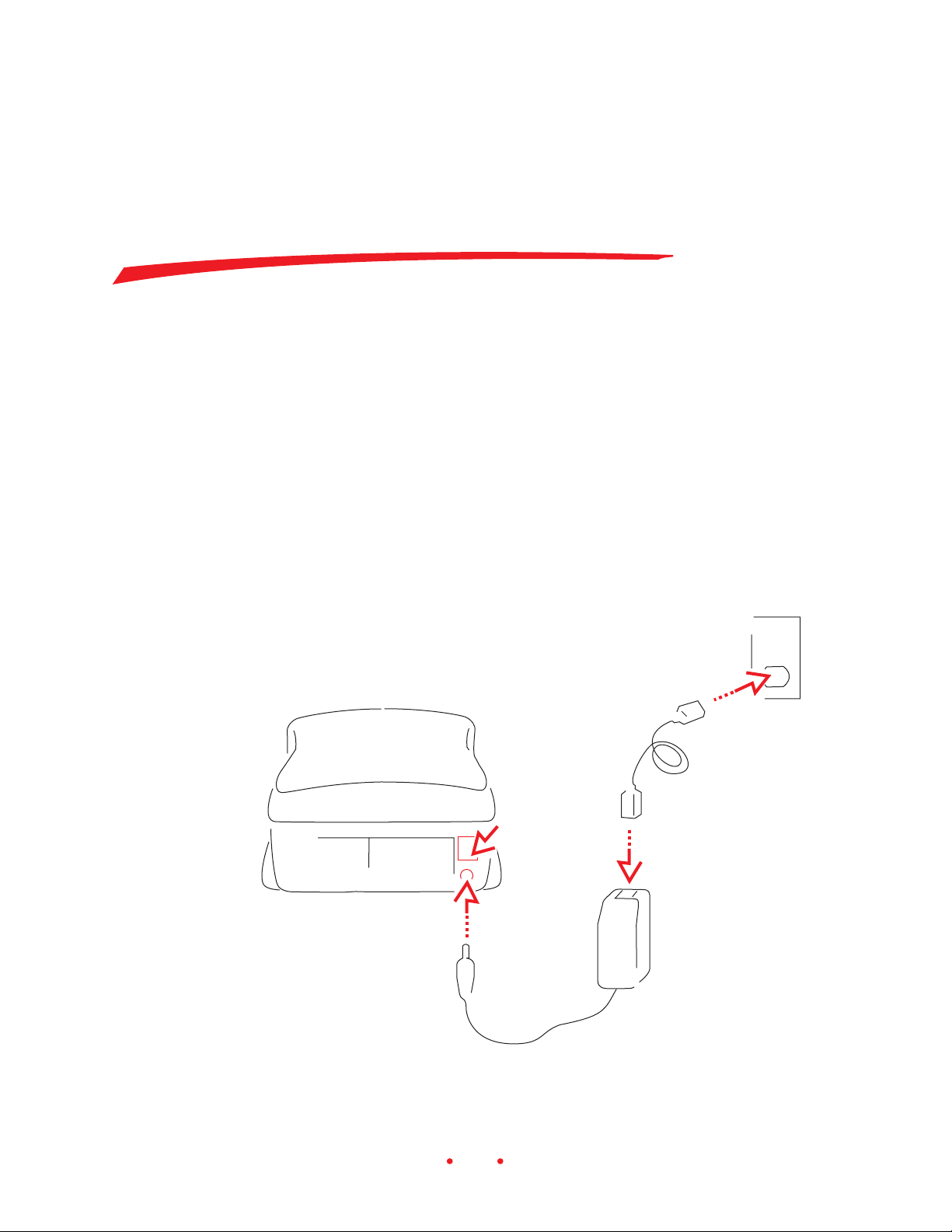
Follow the steps below to connect your scanner to a power source; the
numbers in the artwork correspond to the numbered steps that follow.
5
6
3
4
14
Page 15

1. Remove the scanner from its box and save any packing material.
2. Place the scanner near your computer.
3. Press the off end (O) of the power switch on the back of the scanner to
ensure that the switch is in its off position.
4. Connect the power cable that matches your local power supply to the
AC adapter.
5. Plug the end of the AC adapter cable into the plug on the scanner.
33
3
CAUTION: Use only the AC adapter supplied with the scanner; using
33
any other adapter will void your warranty.
6. Plug the other end of the power cable into a power source.
You are now ready to connect your scanner to your computer using either
the SCSI connection or the USB connection. If you are using a USB connection, skip to Making a USB Connection. Instructions for making SCSI
connections follow.
15
Page 16
MAKING A SCSI CONNECTION
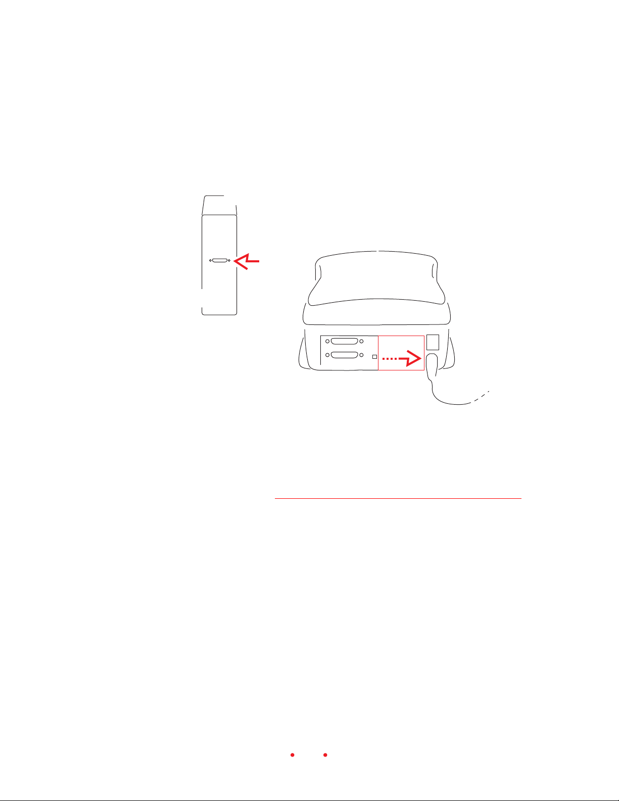
Follow these steps to make a SCSI connection between your scanner and
your computer; the numbers in the artwork correspond to the numbered
steps that follow.
4
3
1. Shut down your computer and all peripherals.
2. PC-compatible customers only. You computer must have a supported
SCSI host adapter card and SCSI software installed to complete the
following steps. The Before you Begin (PC-Compatible Computer)
section of this manual lists supported adapter cards. If a card must be
installed, only trained and qualified technical personnel should install
and configure it.
3. Slide the cover on the back of the scanner to the right to reveal the two
SCSI ports, also called SCSI connectors.
4. Find the SCSI port on the back of the computer (not the scanner), and
determine whether or not one or more external devices such as a disk
drive are already attached to that port in a chain.
5. Select the appropriate instructions from the two sets that follow, according to whether or not other external SCSI devices are connected.
16
Page 17
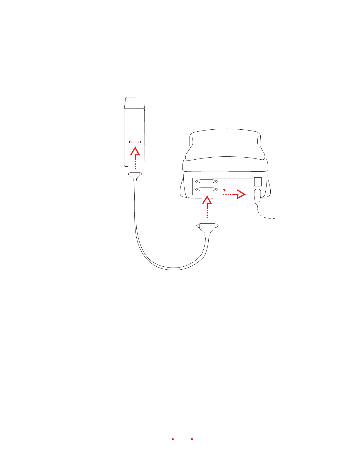
If No External SCSI Devices Are Connected
The numbers in the artwork correspond to the numbered steps that follow.
3
4
5
2
1. Be sure power is turned off to your computer and scanner.
2. Select the SCSI II cable supplied with the scanner.
3. Attach the appropriate end of the SCSI cable to the SCSI port on the
computer; make sure the cable connector is well seated.
Note: If the connectors at the ends of the supplied cable do not allow
you to complete this step, you will need to purchase a SCSI cable that
will complete this connection. Cables are widely available from computer retailers; if you must purchase a cable, be certain to obtain a high
quality cable with a continuous EMI shield over the cable and connectors.
17
Page 18

4. Attach the other end of the cable to either of the identical SCSI ports on
the back of the scanner; again make sure the cable connector is well
seated.
5. Set the SCSI termination switch on the back of the scanner to the on
position.
6. Continue at Setting the Scanner SCSI Identification Number later in
this chapter.
If External SCSI Devices Are Connected
Continue here if multiple SCSI devices are connected to your computer in
a chain. The following steps will help you determine where you should
place the scanner in that chain — either at the end of the chain, or in the
middle of the chain.
The total cable length connecting all devices must not exceed 15 feet (4.6
meters).
1. Be sure power is turned off to your computer, to the scanner, and to all
devices in the SCSI chain (turn off the computer first).
2. Select the SCSI II cable supplied with the scanner.
Note: If the connectors at the ends of the supplied cable do not allow
you to complete the following steps, you will need to purchase a SCSI
cable will complete the chain described below. Cables are widely available from computer retailers; if you must purchase a cable, be certain to
obtain a high quality cable with a continuous EMI shield over the cable
and connectors.
3. Determine if the already connected SCSI devices are terminated or not.
To do so:
A. First look for an external SCSI terminator on the devices; if you find
one (it should be on the last device in the chain), remove it.
B. Because some devices contain internal terminators, also check the
instructions for your devices to determine if they are terminated
internally.
18
Page 19
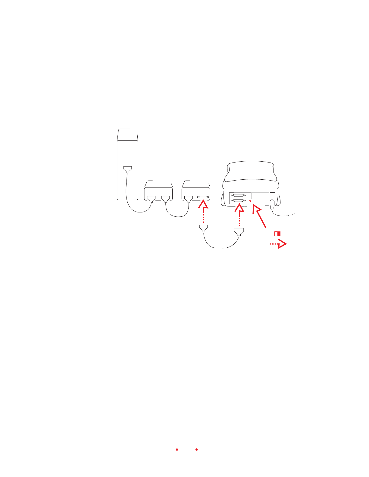
4. If an external terminator has been removed or if none of the connected
devices is terminated internally, follow the directions in this step;
otherwise continue at the next step. In this step, you will place the
scanner at the end of the chain of connected devices; however, you can
place the scanner anywhere in the chain as long as the last device in the
chain is terminated.
A
B
C
A. Attach one end of your SCSI cable to the empty SCSI port on the last
device in the chain; make sure the connector is well seated.
B. Attach the other end of the cable to either of the identical SCSI ports
on the back of the scanner; make sure the connector is well seated.
C. Set the SCSI termination switch on the back of the scanner to the on
position.
D. Continue at Setting the Scanner SCSI Identification Number next in
this chapter.
19
Page 20
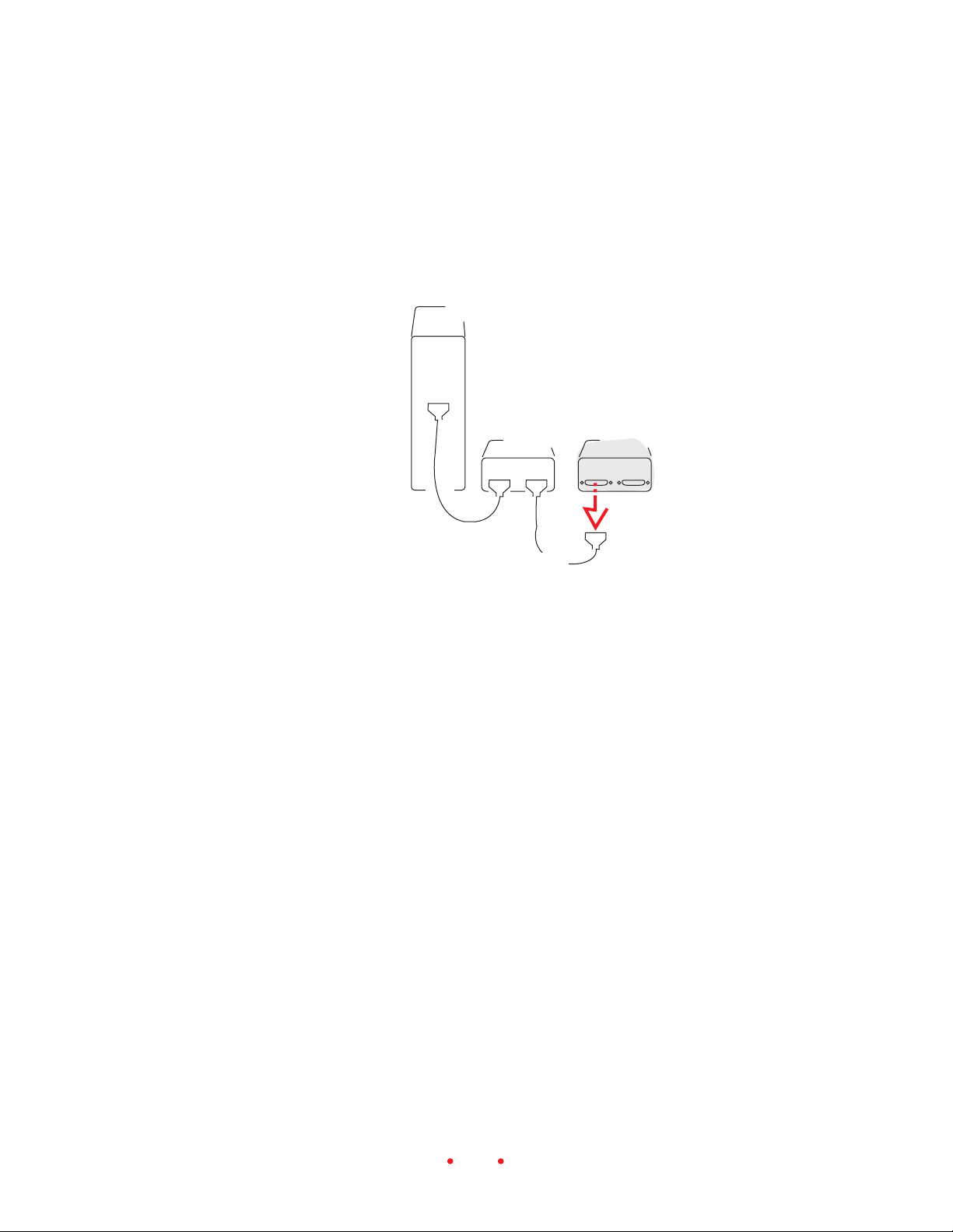
5. Follow this step if one of the connected devices is terminated internally.
In this step, you will place the scanner in the chain just before the
terminated device; however, you can place the scanner anywhere in the
chain between the terminated device and the computer. (The terminated device is shaded in the artwork below.)
B
A
A. Locate the cable leading to the internally terminated device; this
should be the last device in the chain.
B. Disconnect the end of that cable from the internally terminated
device; do not disconnect the other end of the cable.
20
Page 21
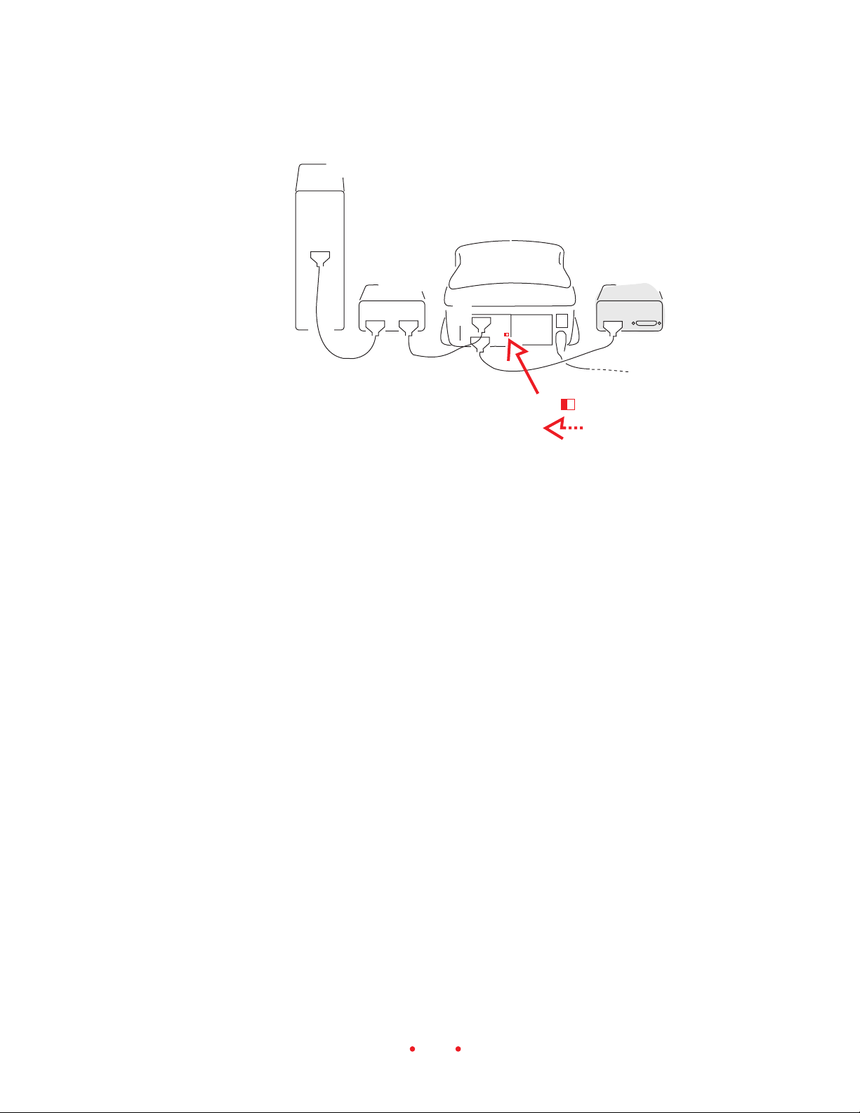
C
D
F
E
G
C. Position the scanner so that you can connect it in the chain before
the terminated device.
D. Attach the end of the cable you just disconnected to either of the
identical SCSI ports on the back of the scanner; make sure the connector is well seated.
E. Attach one end of your SCSI cable to the empty SCSI port on the
scanner; make sure the connector is well seated.
F. Attach the other end of your cable to the empty SCSI port on the
internally terminated device; make sure the connector is well seated.
G. Set the SCSI termination switch on the back of the scanner to the off
position.
Setting the Scanner SCSI Identification Number
Each SCSI device connected to the same computer must have a different
SCSI ID number. Be certain that the number is unique, and assign high ID
numbers to devices used most frequently.
1. If SCSI devices other than the scanner are connected to your computer,
determine their SCSI identification numbers so that you can select a
21
Page 22
different number for the scanner. If necessary, refer to the documentation for those devices to determine how to find their numbers.
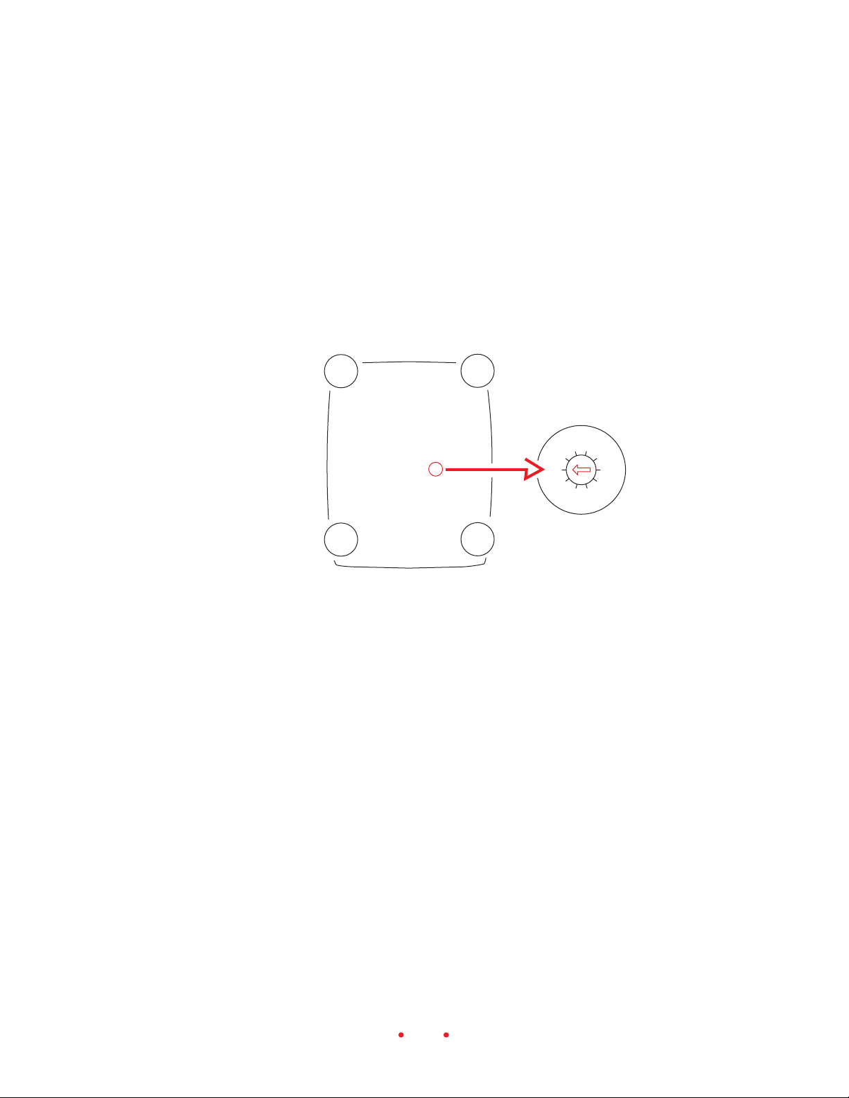
2. Double-check to make sure that the power to the scanner is off; the off
end (0) of the switch should be pressed in and the light near the front
right corner of the scanner should be off. (Make sure the power to the
scanner is off if you change its SCSI ID number at a later time.)
3. Using the guidelines below set the SCSI ID number by turning the SCSI
ID dial on the bottom of the scanner with a small screwdriver.
8
7
9
6
5
0
1
4
2
3
A. Macintosh. If you are working on a Macintosh Computer and are un-
certain of what number to choose, avoid numbers 0, 3, and numbers 7
and above, as well as any other number that has been assigned to another connected device.
B. PC-Compatible. Do not choose 0 or numbers 7 and above. Do not
choose the number of your SCSI host adapter; consult your SCSI host
adapter manual to see if other SCSI IDs should not be used. Do not
choose any other number that has been assigned to another connected
device.
22
Page 23

MAKING A USB CONNECTION
1. If you have not already done so, follow the steps earlier in this chapter
in Connecting the Scanner to a Power Source.
2. Macintosh. Be certain that a USB connector is available on your com-
puter and functioning properly.
3. PC-compatible. Follow this step if you are uncertain if a USB connector
is available and working properly; if all of the conditions below are met,
your computer supports a USB connection.
A. Right-click the My Computer icon on your desktop.
B. Choose Properties from the pop-up menu that appears.
C. Verify that the operating system listed on the Properties screen is
Microsoft Windows 98 or Windows 2000; if it is not, you will not be
able to use the USB port with the scanner.
D. Click the Device Manager tab.
E. Verify that the Universal Serial Bus Controller is listed as a device
and that it appears without any yellow or red indicators.
F. Click the plus sign (+) to the left of the Universal Serial Bus Con-
troller list item to expand it.
G. Verify that a both a controller and a USB Root Hub are listed.
H. Double-click USB Root Hub.
I. Verify that the Device Status in the center of the screen is “The
device is working properly.”
J. Close these dialog boxes.
4. Shut down your computer and all peripherals.
23
Page 24
5. Be sure power is turned off to the scanner.
USB
USB
9
6
7
5
8
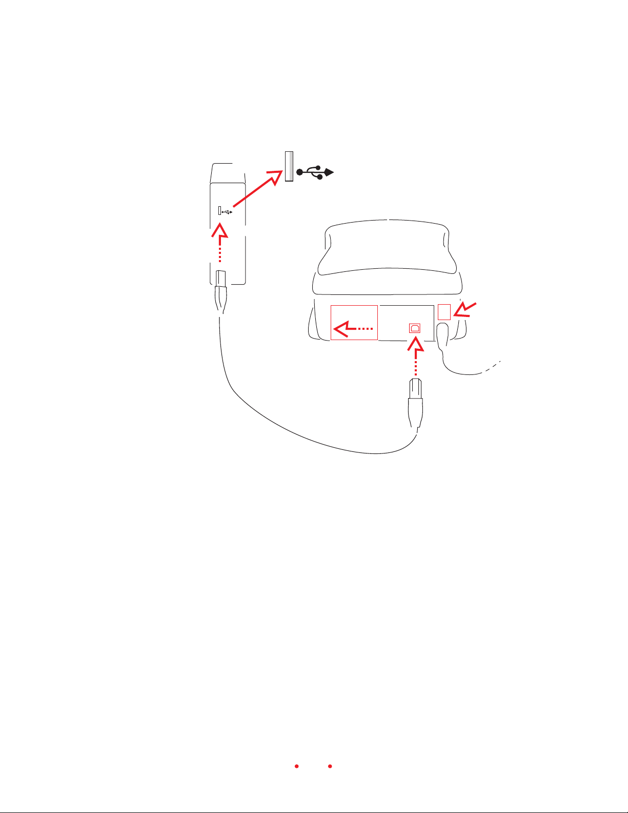
6. Slide the cover on the back of the scanner to the left to reveal the USB
port.
7. Select the USB cable supplied with the scanner.
8. Notice that the included USB cable has different connectors at each
end; attach the appropriate end of the USB cable to the scanner.
9. Connect the other end of the USB cable to the computer.
24
Page 25

Installing Scanner
Software
1. Turn on the scanner and then turn on all other components of your
computer system.
2. Install your copy of Adobe Photoshop if you have not already done so.
3. Make sure the gamma for your monitor is calibrated properly by following instructions in the Photoshop manual.
4. Locate the CD enclosed with the scanner that contains this software:
KODAK PROFESSIONAL RFS 3600 Film Scanner Acquire Module /
for Macintosh.
KODAK PROFESSIONAL RFS 3600 Film Scanner TWAIN Data
Source / for WINDOWS Systems.
5. Close all open programs.
6. Place the CD into your computer.
7. If the installation does not start automatically:
A. Macintosh. Open the window for the CD and run the installer pro-
gram.
B. PC-Compatible. Click Start and click Run. In the Run dialog box,
type D:\setup, and then click OK. (If your CD-ROM drive is not “D”
use its letter instead.)
8. Complete the on-line instructions that appear on the screen.
9. Eject and store the CD; although installing the files is a onetime action,
you may need to reinstall them at a later time.
25
Page 26

Loading Filmstrips
and␣ Slides
FILMSTRIPS
The scanner accepts 35 mm filmstrips from 3-36 frames in length, and
accepts color negatives, color reversals (slide film), and black and white
negative film.
33
3
CAUTION: Never load a single or two-frame film negative. Additionally,
33
spliced film is not supported, and should not be used with the scanner.
Follow these steps to load a filmstrip into the scanner; the computer and
scanner should both be powered on.
1. Since you will be handling film, you may wish to wear protective gloves
when loading the filmstrips.
2. If numbered identification labels of any kind are stuck on either end of
the film, cut those off, as long as the remaining filmstrip will be at least
three frames in length. (The scanner does not accept filmstrips shorter
than three frames.)
3. If the film has a blank leader at either end cut the leader off, as long as
the remaining filmstrip will be at least three frames in length.
4. Be certain the filmstrip is clean and dust free; if not, clean it as needed.
26
Page 27

5. Orient the filmstrip as follows:
The film should be fed from the left of the scanner.
The highest frame number should enter the scanner first.
Data on the edge of the filmstrip should be at the top of the film.
These actions should result in the emulsion side of the film being face
down.
7A
7B
7C
6
6. Gently move the filmstrip into the scanner from the left until the scanner detects the film and pulls the film into the scanner.
7. Use the buttons on top of the scanner to reposition the filmstrip as
follows:
A. Eject. This button ejects the filmstrip to the left, out of the scanner.
As we’ll explain later, this button has the same function as the Eject
Reverse button in the scanner software.
B. Reverse. This button performs two different functions. Tap the
button to move the filmstrip to the left (reverse) in fine increments
over the current frame. Press and hold this button for approximately
one-half second to move the filmstrip one full frame to the left. (As
we’ll explain later, this button performs the same two functions as
the Reverse button in the scanner software.)
27
Page 28

SLIDES
The scanner accommodates one mounted 35 mm slide at a time; no slide
holder is used.
C. Forward. This button performs two different functions. Tap the
button to move the filmstrip to the right (forward) in fine increments over the current frame. Press and hold this button for approximately one-half second to move the filmstrip one full frame to
the right. (As we’ll explain later, this button performs the same two
functions as the Forward button in the scanner software.)
1. Be certain the slide is clean and dust free; if not, clean it as needed.
2. Orient the slide as follows:
The top of the slide should enter the scanner first.
The image should be oriented so that the image is facing you, as you
would see it in real life (not mirror-imaged).
3. Hold the slide mount with your thumb and forefinger, and gently push
the slide into the slot on the front of the scanner until the slide is at the
rear of the slot.
4. When you are ready to remove the slide, extend your thumb and forefinger into the opening and pull the slide from the scanner.
IMPORTANT: The Eject button on top of the scanner does not function with slides.
28
Page 29

Tutorial:
Using␣ Scanner␣ Software
There is no one ‘correct’ way of using the scanning software; instead, there
are many different paths, depending on your individual requirements. This
section provides one possible path, and provides an overview of software
features. For more details on each software feature refer to Reference –
Software.
This manual assumes that you are familiar with the operation of your
computer and of Adobe Photoshop, and that you have your scanner connected properly to your computer as described in Connecting the Scanner
to Your Computer. It also assumes that you have read and are familiar with
the material in this manual in these sections: Important Safeguards and
Precautions, Installing Scanner Software, and Loading Filmstrips and
Slides.
The initial sections of this part of the manual discuss how to scan a single
image. However, it is also possible to select multiple images and scan them
in a batch; the concepts involved are discussed later in Working with Mul-
tiple Selected Images.
OPEN SCANNER SOFTWARE
Follow the steps in this section each time that you want to use the scanner.
1. With your computer, scanner, and other devices (if present) turned off,
turn on the scanner by pressing the on (|) end of the power switch on
the back of the scanner. The light on the top of the scanner turns on.
The scanner performs a start-up procedure and then is ready for use.
33
3
CAUTION: If you are using a SCSI connection for the scanner, always
33
turn on the scanner before you turn on your computer.
29
Page 30

2. Turn on other devices if present.
3. Turn on your computer.
4. Open Adobe Photoshop.
5. Open the scanner window on your Macintosh or PC-compatible as
follows. (If the scanner choices do not appear as expected, repeat the
steps in Installing Scanner Software to reinstall the scanner software.)
Macintosh. Choose KODAK RFS 3600 from the Import submenu of the
Adobe Photoshop File menu; the scanner software window appears.
PC-compatible. Follow these steps:
A. Choose Select TWAIN_32 Source on the Import submenu of the
Adobe Photoshop File menu; the Select Source dialog box appears.
B. Click RFS 3600 TWAIN Data Source.
C. Click Select; you are returned to Adobe Photoshop.
Note: You do not need to repeat steps A through C each time you
use the software; instead, on future uses of the software just follow
part D of this step.
D. Choose TWAIN_32 on the Import submenu on the File menu; the
scanner software window appears.
30
Page 31

6. You see this screen; it has a central set of three tabs (Settings, Color
Balance, and Levels & Curves) surrounded by general controls.
(Refer to Messages if a message indicates that the scanner was not
found.)
PRODUCE SCANNED IMAGES
In a typical work session you might follow these summary steps. After the
listing below, each step is explained in tutorial form.
A. Establish scanner settings — film type, profiles, color depth, etc. — on
the Settings tab.
B. Prescan your filmstrip or slide; image thumbnails appear across the top
of the screen.
C. Rotate, flip, and crop as needed.
31
Page 32

D. Set the output size — including width and height, magnification, and
resolution.
E. Adjust color with the controls on the right of the screen.
F. Fine-tune color on the Color Balance and Levels & Curves tabs.
G. Generate scans of images.
H. Save settings and quit the software.
Note: If you follow these steps on your computer, and wish to quit in the
middle of the tutorial, you can click the Exit button to close the scanner
software window.
A. Establish Scanner Settings (Settings Tab)
1. Load a filmstrip or slide into the scanner as described in Loading Film-
strips and Slides; in this section the manual will assumes that you have
loaded a filmstrip.
2. Set the Film Type.
A. Choose color Negative, color Reversal (slide film), or B&W (black
and white) negative.
B. Select the specific film type from the choices on the drop-down
menu.
3. Set Profiles.
A. Select your color monitor from the drop-down Monitor list; if your
monitor is not listed, choose Generic Monitor. The color of previews performed by the scanner software will be adjusted based on
the monitor you choose.
32
Page 33

B. Select your output space (for example a specific printer), from the
drop-down Output list of International Color Consortium (ICC)
profiles. If your desired output color space is not listed, choose
KODAK sRGB Display.
4. Set Color Depth by choosing either 8 Bit or 12 Bit per channel from the
Color Depth drop-down list. Refer to Reference – Software, Color
Depth for additional information.
B. Prescan Your Film
With a filmstrip, you can select a single image to prescan (step 1 below), or
you can prescan the filmstrip in its entirety (step 2 below), which requires
considerably more time for a long filmstrip. Both options are explained,
but it is suggested that even if you will prescan a full strip, that you start
with step␣ 1 to ensure proper frame alignment.
1. Prescan a single image.
A. Advance the filmstrip to the desired image using the Reverse and
Forward buttons in the Film Motion area of the software. From left
to right the buttons below are Reverse Eject, Reverse, Forward, and
Forward Eject. (You can also use the buttons on top of the scanner
to reposition the filmstrip as described earlier.)
B. Prescan the single frame currently located in the scan position in the
scanner by clicking the Prescan Frame button.
33
Page 34

C. If the frame is not centered properly in the scan position, tap the
Reverse or Forward buttons on top of the scanner as needed to move
the filmstrip in fine increments over the current frame. As you do,
you can watch the film movement through the viewer on the top of
the scanner to ensure that the frame is properly centered. Then click
the Prescan Frame button again. You can perform the same function
in the software as described in Reference – Software (Film Motion).
2. Prescan the full filmstrip.
Click the Prescan Strip button; the entire filmstrip is prescanned,
thumbnails appear across the top of the screen, and the first image
scanned automatically appears in the image area in the center of the
screen. The screen examples in the remaining portions of this chapter
assumes you have prescanned a filmstrip rather than a single image.
(If you wish, you can press the cancel button you see in the dialog box
at any time to cancel the prescan strip action before it prescans all
frames on the filmstrip.)
34
Page 35

3. Scroll the thumbnails by clicking the arrows at either end of the thumbnails until the image you want to scan is visible.
4. Click the thumbnail of the image you intend to scan in a later step; a
red border surrounds the thumbnail and the image appears in the
preview image window in the center of the screen.
C. Rotate, Flip, Crop
1. (Optional.) Use the image rotation buttons to rotate the image, and its
thumbnail, 90 degrees counterclockwise, 180 degrees, or 90 degrees
clockwise.
2. (Optional.) Use the flip buttons to flip the image, and its thumbnail,
horizontally or vertically.
3. (Optional.) Crop the image by dragging the pointer from corner to
corner across the area you want to crop; a crop box surrounds the
selected area. The effect of the crop takes place later when the image is
scanned.
4. (Optional.) Resize the crop box by moving the pointer over any edge or
corner of the crop box, then drag to the desired size. To move an existing crop box, move the pointer inside the crop box, then drag to the
desired location. To remove the crop box, click outside of the crop box
on the preview image.
35
Page 36

D. Set Output Size (Width/Height, Magnify, Resolution)
This section provides a brief explanation of several of the items in the
Output Size area of the Settings tab. For a full explanation refer to the
Output Size and Input Values section of this manual.
You control what portion of the frame will be scanned and at what resolution. One way you control the part of the frame to be scanned is by dragging a crop box as explained above; this results in changing the Scan Area
(Width and Height) shown on the screen to the right of the image. You
control the scanning resolution (also to the right of the image, as the Input
Res) indirectly as explained below.
You control the dimensions of the resulting image by changing the Width
and Height (Output Size). Finally, you control the output resolution by
changing the Resolution (Output Size).
The translation from Scan Area and Input Res to the dimensions and resolution of the scanned image is controlled by the same magnification (Input
Size Magnify). But magnification affects the translation of dimension and
resolution differently. The more you increase the dimension of the output
image, the smaller the output resolution will be because the scanned image
has to be spread over a larger area than on the film. The more you decrease
the dimension of the output image, the higher the output resolution will be
because the scanned image has to be compressed into a smaller area than
on the film.
Because of the interrelationships between width, height, resolution and
magnification of input and output, whenever you change one of these
values, the software will automatically change one or more of the other
values to compensate. Also, the Output Size Lock box, when on, freezes the
output dimensions, and therefore the Scan Area is forced to maintain the
aspect ratio defined by the Output Size Width and Height.
36
Page 37

The following table lists the guidelines the software follows for changing
values.
If you change .␣ .␣ . The software will change this .␣ .␣ .
Output Size Resolution Scan Resolution (Input Res on the screen)
Output Size Width Scan Area Width
Output Size Height Scan Area Height
Scan Area Height Output Size Height
(by dragging a crop box) (if Output Size Lock is off)
Scan Area Width, Magnify, and Output Size Resolution
(if Output Size Lock is on)
Scan Area Width Output Size Width
(by dragging a crop box) (if Output Size Lock is off)
Scan Area Height, Magnify, and Output Size Resolution
(if Output Size Lock is on)
Magnify Output Size Width, Height, and Resolution
(if Output Size Lock is off)
Scan Area Width, Height, and Input Res
(if Output Size Lock is on)
The general rule is that the software will try to change a width or height
(output or scan) first, and avoid changing the Magnify value. The only time
the software needs to change the magnification is when you have the Output Size Width and Height locked, and you crop. This also results in a
change to the Output Size Resolution.
With these considerations in mind we’ll establish a global measurement
unit preference for the software and then present two simple examples
involving these settings.
1. Select the desired measurement unit — centimeters (cm), inches (in),
or pixels (px) — by clicking on the small button at the intersection of
the rulers at the top left corner of the preview image. With each click,
you are rotated through the three measurement units. The units you
select here are used throughout the software.
37
Page 38

2. Cropping the image.
A. Drag a crop box.
B. As needed, change Magnify. This changes the output dimensions
without affecting the Scan Area.
3. Maintaining a specific Output Size.
A. Enter the desired values for the Output Size Width and Height.
B. Check Lock on to ‘freeze’ the Output Size Width and Height. If the
Output Size aspect ratio (width vs. height) doesn’t match the aspect
ratio of a 35 mm frame, a crop box will appear that has the aspect
ratio. One dimension of the crop box will be set to its maximum,
while the other dimension will be less than its maximum and centered in the frame.
C. Drag the crop box to a different area of the image as needed.
This will create a scan that’s twice the length and width of the 35 mm
frame. As you enter values for different parameters in this area of the
software, other values change automatically. Note that the File Size
appears on the screen, as does the Scan Area. The scan resolution also
appears; in this case it is 3000 dpi, the value that will result in an output
Resolution of 1500 dpi with a Magnify value of 200%.
As you change these values, you may encounter messages indicating that
the scanner cannot complete the scan at the parameters you’ve established.
For additional information on the interactions of these parameters, refer to
the Output Size and Input Values section of this manual.
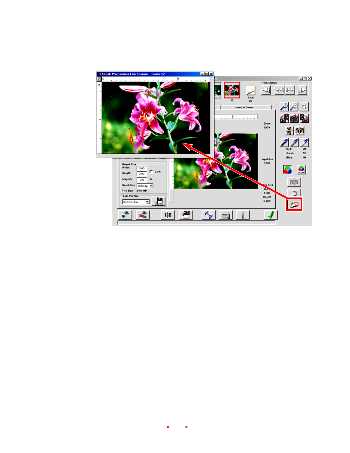
E. Adjust Color (Click Balance, Auto Balance, Default Balance,
Sharpening)
1. (Optional.) Click the Image Window button to display a second window
— the image window — that floats on top of the main window. You’ll
use this window to enhance the view of color changes made to the
image; if you work with this window you should enlarge the window for
a better preview.
38
Page 39

Note: Opening this window is a convenience for you, and is therefore
optional; the same functionality is available whether this additional
window is opened or closed.
2. (Optional.) Use the two zoom buttons to zoom in or out on the image.
Clicking a zoom button turns it on, then click the image; turn it off by
clicking the button again (or it turns off automatically when it reaches
its limit).
3. (Optional.) Once you zoom in, you can use the Move button to drag to
a different area of the image in the window; click Move to turn it on,
drag the image, then click the button again to turn it off.
39
Page 40

4. (Optional.) Use the color balance buttons on the main window to
adjust color in the image as described in this step. The results of these
actions are visible on the large image, but not on the thumbnail. (The
thumbnail only reflects changes to rotation and flipping; other image
adjustments are not shown on the thumbnail.)
Note that as you move the pointer over the image, the CMYK or RGB
color values for the single pixel below the current pointer location
appear to the right of the image screen. Whether you see CMYK or RGB
values depends on the Output choice you have made in the Profiles area
of the Settings tab.
or
Click the Auto Balance button on/off (button down/button up) to
control whether the Scene Balance Algorithm is applied or not. The
Kodak-developed Scene Balance Algorithm (SBA) optimizes color
balance and density. It is automatically on (down) for a Film Type
of Negative or B&W; however, you can then click the button to turn
it off, thereby removing the effects of the SBA. If you prescan with a
Film Type of Reversal, the SBA is not applied by default and the
button remains off (up); however, you can click it to activate the
SBA.
Use the Black, Gray, and White pointer buttons for rapid, automatic
adjustment of the color balance of images. Two clicks are required
for this feature to be performed. First you click on one of these
buttons, for example the White Pointer button, at which time the
pointer changes to an eyedropper representing the button. Then the
second click should be on a spot in the image that you know should
be white. The image is automatically adjusted for color balance
based on forcing the spot you clicked to become white, and the
results are immediately evident on the displayed image. If necessary,
40
Page 41

click the button again to cancel the adjustment. You can also
double-click on the Black or White pointer buttons for even more
control of this function as explained in the Reference – Software
(Black Pointer, Gray Pointer, and White Pointer) section of this
manual.
After the second click, the button remains down, a visual indication
that this click-balance feature has been applied to the image.
Click the Default Balance button to apply the default color balance,
thereby undoing any changes you’ve made with the Black, Gray,
and/or White pointer buttons. However, this button does not undo
the Scene Balance Algorithm applied with Auto Balance.
5. (Optional.) Click the Undo button to undo the last function performed;
one level of undo is supported.
6. (Optional.) Choose a Sharpening level of Off, Low, Medium, or High to
adjust the level of edge definition between image elements (pixels); high
provides the most definition.
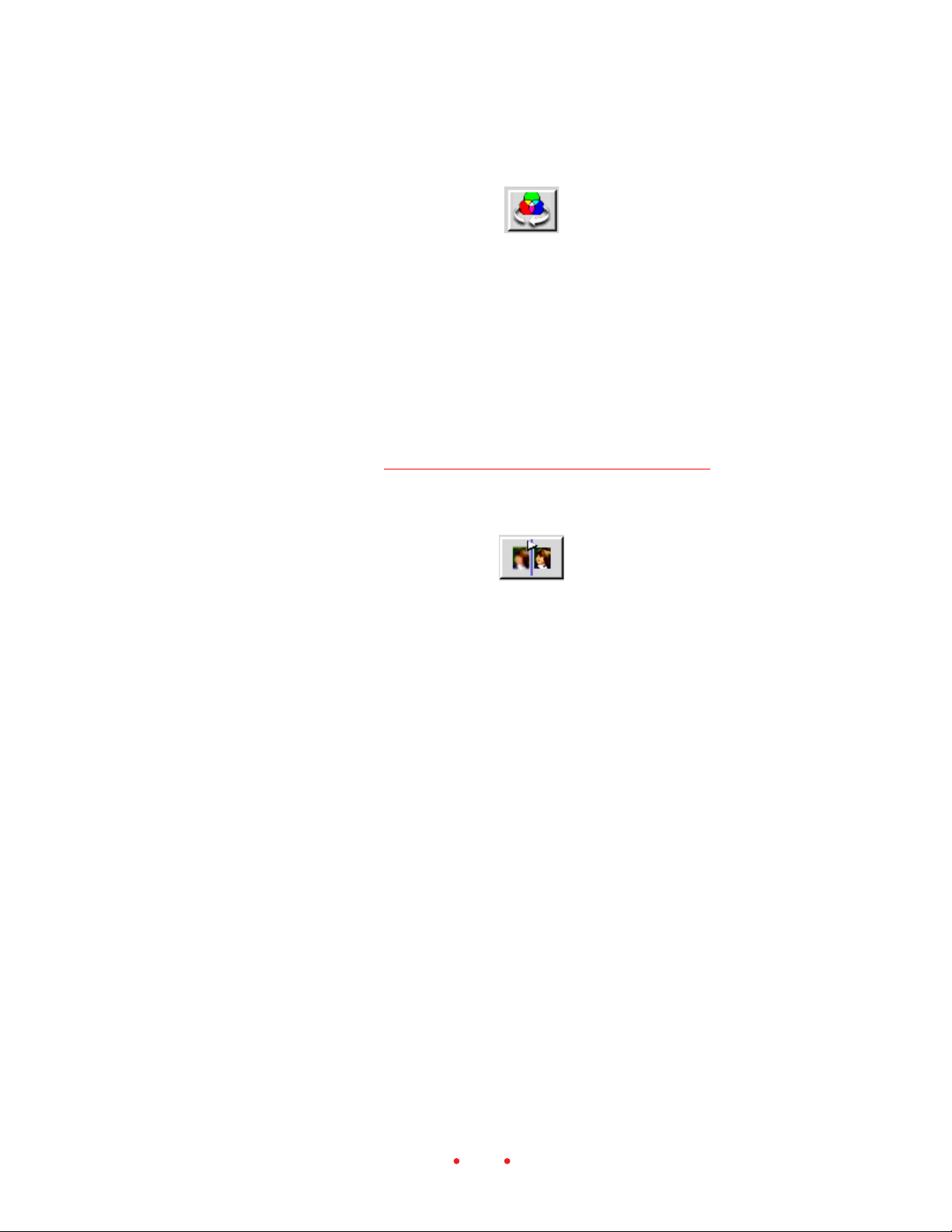
F. Fine-tune Color (Color Balance and Levels & Curves Tabs)
1. (Optional.) Click the Color Balance tab to access controls for color
balance, brightness, contrast, and saturation. Note that a Before and an
After version of the current image appear on this tab; they are identical
41
Page 42

when you enter the tab. When you leave this tab, the image in the After
position becomes the updated image on all screens.
2. (Optional.) Adjust the values for Brightness, Contrast, and Saturation
by dragging their sliders or by entering an integer from -100 to +100
into the field next to the slider; the numbers represent percentage
values.
3. (Optional.) Adjust the values Cyan/Red, Magenta/Green, and Yellow/
Blue by dragging their sliders or by entering an integer from -100 to
42
Page 43

+100 into the field next to the slider; the numbers represent percentage
values.
4. (Optional.) If necessary, click the Reset button to undo all color balance
adjustments made to the image using the sliders during this visit to this
tab. (The Undo button reverses only the last slider change while this
Reset button will undo all slider changes you’ve made since entering
this tab.)
5. (Optional.) Click the Levels & Curves tab for more advanced tools for
adjusting color. On this tab, the Before and After versions of the image
work as described just above for the Color Balance tab.
43
Page 44
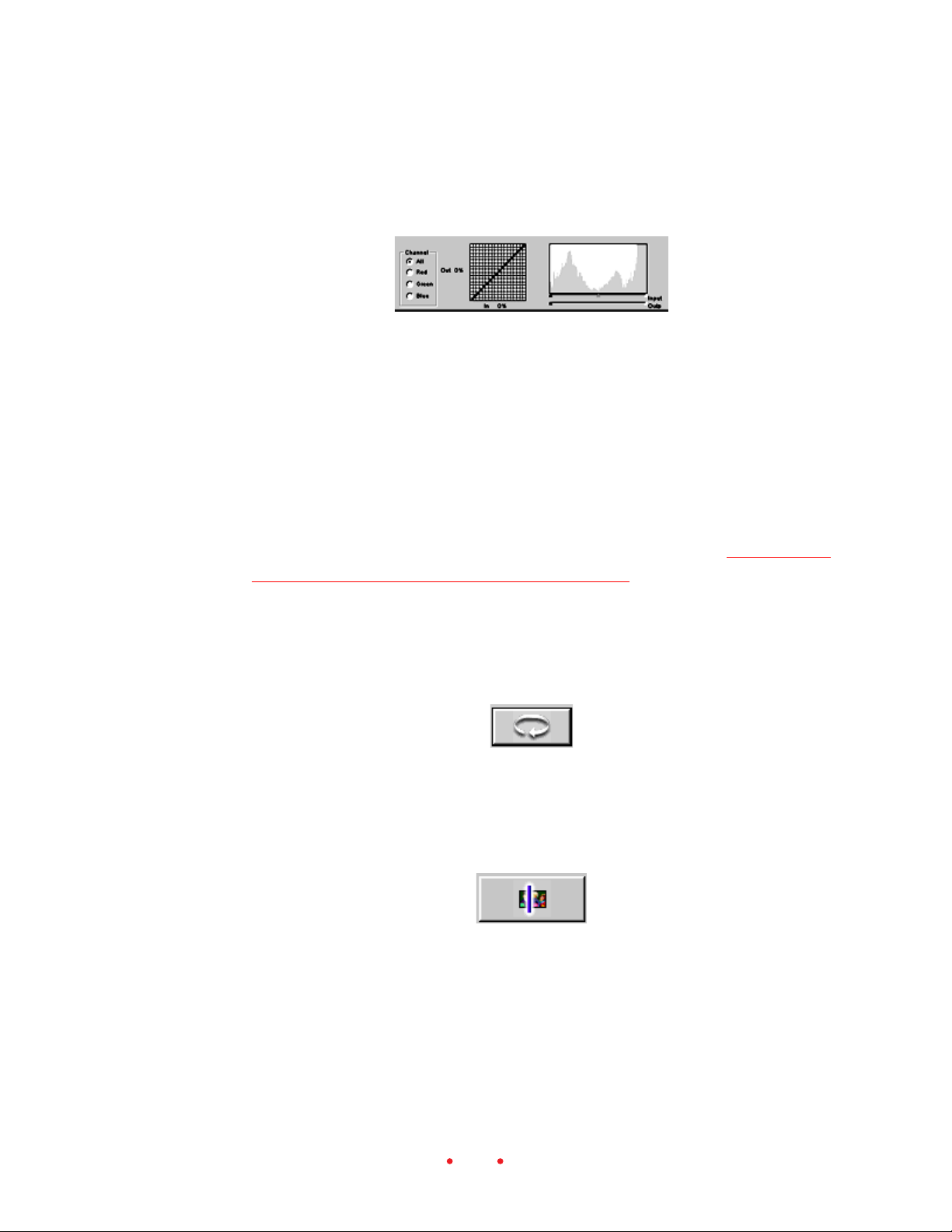
6. (Optional.) Set the channel to All, or separately to Red, Green, or Blue;
the histogram and tone curve choices (see just below) apply to your
Channel selection.
7. (Optional.) Create up to 4 new points on the tone curve by clicking in
the grid or Control-clicking (Windows) or Command-clicking
(Macintosh) on the desired position on the Before image. Points on the
curve are fixed until you move or delete them. Move a point by dragging it to a new location; delete a point by dragging it off the side of the
curve.
The histogram and tone curve functions behave consistently with their
implementations in Photoshop version 5.0 and later.
For information on the Input and Output sliders refer to Reference —
Software (Channels, Histograms, and Curves).
8. (Optional.) If necessary click the Reset button to undo all color adjustments made to the image during this visit to this tab. (The Undo button
reverses only the last change while this Reset button will undo all
changes you’ve made since entering this tab.)
G. Generate Scans
1. Click the Scan button to perform a scan on the selected frame. The
result of this scan will be an image in a Photoshop window.
44
Page 45

2. (Optional.) As an alternate to the Scan button, you can click the Scan to
File button. The resulting image from this scan is saved directly as a
file, without the intermediate step of opening the image in a Photoshop
window. In the dialog box that appears, select a location for the file and
the file type, and enter a filename.
H. Save Settings and Quit
Finally, you will save the current settings and leave the scanner software.
1. (Optional.) Click the Manage Scan Profile button to save current settings from all three tabs; this provides a method you can use to recall a
setup for future scanning tasks. Enter a name for the current profile on
the dialog box that appears.
This feature allows you to create custom profiles (for example “Winter
Outdoors”) for specific or unique shooting conditions. Then, in a later
work session, you can select these profiles by name from the drop-down
list box that appears in this area.
2. Remove the filmstrip from the scanner by pressing the Eject button on
the top of the scanner, or by clicking the Reverse Eject or Forward Eject
buttons in the Film Motion area of the scanner software.
3. Quit the scanner software by clicking the Exit button. If you have
prescanned images but not scanned them, you’re asked to confirm that
you want to leave the software. Even if you do not save settings with a
name, as described above, the current scanner setting are saved, and
become the default settings the next time the scanner software is
opened.
45
Page 46

4. You are returned to Photoshop where you can work with the image as
needed (assuming you have scanned the image to a Photoshop window).
5. Edit and save the image in Photoshop as needed.
6. Quit Photoshop.
7. Turn off your computer.
8. Turn off the scanner.
46
Page 47

Reference – Hardware
The KODAK PROFESSIONAL RFS 3600 Film Scanner includes the following hardware features.
POWER CONNECTOR AND ON/OFF SWITCH
The power connector accepts the plug at the end of the AC adapter cable.
33
3
IMPORTANT: Use only the AC adapter supplied with your KODAK PRO-
33
FESSIONAL RFS 3600 Film Scanner.
The On/Off switch turns the scanner on or off.
The green LED at the top right of the scanner indicates scanner status as
follows:
The LED is on, but not flashing. The scanner is on.
The LED flashes. This occurs during a variety of normal scanner actions
such as completing a self-test, calibrating the light source, moving a
filmstrip, or scanning your film.
The LED flashes in an unending, repeated pattern. A problem has been
detected with the scanner; turn off your computer system and scanner,
and restart.
FOUR OPERATING BUTTONS
Eject. This button ejects the filmstrip to the left, out of the scanner; this
button has the same function as Eject Reverse in the scanner software.
There is no eject button for a slide; a slide must be removed by hand.
Reverse. This button performs two different functions. Tap the button
to move the filmstrip to the left (reverse) in fine increments over the
current frame. As you do, you can watch the film movement through
47
Page 48

the viewer on the top of the scanner to ensure that the frame is properly
centered. Press and hold this button for approximately one-half second
to move the filmstrip one full frame to the left. This button performs
the same two functions as the Reverse button in the scanner software.
Forward. This button performs two different functions. Tap the button
to move the filmstrip to the right (forward) in fine increments over the
current frame. As you do, you can watch the film movement through
the viewer on the top of the scanner to ensure that the frame is properly
centered. Press and hold this button for approximately one-half second
to move the filmstrip one full frame to the right. This button performs
the same two functions as the Forward button in the scanner software.
Scan. Press this button to perform a scan on all selected frames (thumbnails with a red border in the scanner software); if no images are selected (you have created no previews), this button creates a scan from
the current frame positioned in the scanner. To use this button,
Photoshop must be open, and the scanner software must be running.
The resulting image from each scan appears in a separate Photoshop
window. This button performs the same function as the Scan button in
the scanner software.
COMPUTER CONNECTIONS (SCSI AND USB)
The scanner can be connected to your computer with either a SCSI II
connection or a USB connection.
SCSI Connectors and SCSI ID Controller
The scanner is equipped with two SCSI II connectors; this allows the scanner to be connected at any point in a SCSI chain. A switch on the back of
the scanner allows you to turn the internal terminator on or off. Refer to
Connecting the Scanner to Your Computer for complete details.
SCSI ID Switch
The SCSI ID dial allows you to set the desired SCSI ID for the scanner.
USB Port
The USB-ready scanner includes a USB port.
48
Page 49

Reference – Software
Note that the software screen consists of a central area displaying three
tabs, as well as additional buttons and controls that surround the tabbed
area.
This software reference is divided into five sections:
General Screen layout.
The Settings tab.
The Color Balance tab.
The Levels & Curves tab.
Working with Multiple Selected Images.
GENERAL SCREEN LAYOUT
Thumbnail Images
This area displays thumbnails of frames you have prescanned. To generate
thumbnails, click either the Prescan Frame button or Prescan Strip button.
When working with a filmstrip (rather than a film slide), up to 6 sequential
thumbnails can be displayed in this area, while with slides only a single
image is displayed. This area of the screen is empty if you have not
prescanned any images.
As you use the features of the software, only rotation and flipping are
shown on the thumbnail; other image adjustments, although shown in the
image area, are not reflected on the thumbnail.
49
Page 50

The scanner software assigns sequential frame numbers to filmstrip thumbnails. These numbers, which appear below the thumbnails, do not necessarily match the frame numbers on the filmstrip. For example if the first
image you prescan is from the middle of a filmstrip, it will still be numbered “1” under its thumbnail.
Total Number of Prescanned Images
The total number of images that have been prescanned from this filmstrip
appears beneath the word “Total” on the screen, as shown above. If you
have not prescanned the entire filmstrip, then this number will not match
the total number of frames on the filmstrip.
Scroll Left and Scroll Right Buttons (Scroll Filmstrip
Thumbnails)
If more than six images have been prescanned, you can use the Scroll Left
and Scroll Right buttons (one is at each end of the strip of thumbnails) to
scroll through the thumbnail images. They do not move the filmstrip in the
scanner; instead, they control the display of thumbnails for the frames you
have already prescanned. Each click on one of these buttons scrolls thumbnails one frame to the left or to the right respectively. Scrolling does not
affect the selection of thumbnails (those with a red outline), nor does it
change the preview image displayed in the main image area in the center of
the screen.
Selecting/Deselecting Thumbnails
By default, the first image prescanned is ‘selected,’ meaning that a red
outline surrounds its thumbnail, and that a larger version of this image
appears in the preview image area in the center of the screen.
You select a different image by clicking on its thumbnail, at which point
the red outline surrounds the new thumbnail and is removed from the
previously selected thumbnail. The new image replaces the previous image
in the preview image area.
You can also select and work with more than one thumbnail at a time, as
explained in Working with Multiple Selected Images.
50
Page 51

Film Motion (Reverse Eject, Reverse, Forward, Forward Eject)
From left to right these four buttons represent Reverse Eject, Reverse,
Forward, and Forward Eject; they generate commands that move the filmstrip in the scanner. Clicking Reverse or Forward moves the filmstrip one
frame at a time in the designated direction. Clicking Reverse Eject or Forward Eject moves the filmstrip in the designated direction until the film is
clear of the scanner. The buttons are not enabled unless there is a filmstrip
in the scanner. There is no eject button for a slide; a slide must be removed
by hand.
You can also move the filmstrip in either direction in fine increments,
rather than a full frame at a time. This helps you ensure that an individual
frame is properly positioned in the scanner. To do so:
Macintosh. Option-click (hold down the Option key, click Reverse or
Forward, release the key).
PC-Compatible. Control-click (hold down the Ctrl key, click Reverse or
Forward, release the key).
You can verify the positioning of the film by watching the frame through
the view window on top of the scanner as you use these buttons. Once you
have properly positioned the filmstrip, you can create thumbnails by clicking Prescan Frame or Prescan Strip, or you can scan images directly without creating a thumbnail by clicking Scan or Scan to File.
Zoom In and Zoom Out
Use these two buttons to zoom in or out on the preview image as follows:
1. Click either zoom button to turn it on.
2. Click a spot in the preview image; the image is zoomed (in or out, depending on which button you clicked) and centered on the spot you
click.
51
Page 52

3. Click the same zoom button to turn it off (or it turns off automatically
when it reaches its limit).
The current zoom percentage is displayed on the main window to the
upper-right of the preview image; for example “Zoom 100%” indicates that
the image is displayed at full size.
Move
Click this button to turn the pointer into a hand icon, which when dragged
on the preview image, changes the portion of the image displayed. Click the
button again to turn this function off. This action is useful when the image
has been enlarged with the zoom function.
Image Rotation (90° Counterclockwise, 180°, 90°␣ Clockwise)
Click the appropriate button to rotate the preview image, and its thumb-
nail, 90° counterclockwise, 180°, or 90° clockwise.
Flip Horizontal and Flip Vertical
Click the appropriate button to flip the previewed image, and its thumbnail, horizontally or vertically.
Black Pointer, Gray Pointer, and White Pointer
Use these buttons — Black, Gray, and White pointers — to adjust the color
balance of images. These buttons can be used on the preview image on the
Settings tab, or in the Image Window, or with the After images on the
Color Balance and Levels & Curves tabs. (If the Image Window is opened,
52
Page 53

you must apply these features to the image in that window and not in the
preview image or the After image beneath.)
As you use these buttons with one of those images, two clicks are required
for this feature to be performed. First you click on one of these buttons, for
example the White Pointer button; the pointer changes to an eyedropper
representing the button. Suppose that you click the White Pointer; then the
second click should be on a spot in the Settings tab image (or the After
image on the other tabs), that you know should be white. The color balance
of the image is automatically adjusted based on forcing the spot you clicked
to become white, and the results are immediately evident on the After
image. If necessary, click the button again to cancel the adjustment.
The Black Pointer and Gray Pointer perform the same function, but your
second click should be on an area that should be black for the Black
Pointer or an area that should be gray (also referred to as neutral) for the
gray Pointer. With all three buttons, do not click a dark shadow or a bright
highlight or an overexposed area.
Once you click on the image, the button remains down, an indication that
you have performed that particular color balance.
You can also double-click on the Black or White pointer buttons to display
a dialog window in which you can define numeric values for black or white.
For example, if you know that the value 230 should indeed be white, you
can double-click on the White Pointer button and enter 230 in the dialog
box.
Let’s explain how this button works in conjunction with the Auto Balance
button.
First, Auto Balance is turned on (the button is down) automatically for
a Film Type of color Negative or B&W, and is turned off (the button is
up) automatically for a Film Type of Reversal. However, you can then
turn Auto Balance off or on manually if you wish.
Now, you can use any of the three click balance buttons while Auto
Balance is either on or off. If Auto Balance is on, the results of each
click balance button is “added” to the existing effect of the Auto Balance button. However, while Auto Balance is off, just the result of your
action with each click balance button is applied.
53
Page 54

You can click the Default Balance button to cancel the effect of your work
with the three separate click balance buttons.
For an explanation of the effect of these buttons when more than one
image is selected, refer to Working with Multiple Selected Images.
CMYK or RGB Values
These fields display the color values for the single pixel below the current
pointer location. (The Output Profile you have previously chosen on the
Settings tab determines whether CMYK or RGB values appear.)
Auto Balance
or
Toggle this button on/off (button down/button up) to control whether the
Scene Balance Algorithm is applied or not; the result of this action is immediately apparent on the image. The Kodak-developed Scene Balance
Algorithm (SBA) optimizes color balance and density during first-time
scans of color negative and B&W films.
If you select a Film Type of color Negative or B&W, the SBA is activated by
default and this button will automatically appear in the on position
(down); however, you can then click the button to turn it off, thereby
removing the effects of the SBA. If you select a color Reversal (slide film)
film type, the SBA is not applied by default and the button remains off
(up); however, you can click it to activate the SBA.
You can use this button in concert with any of the click balance buttons
(Black, Gray, and/or White pointers), in which case they work together,
rather than one of them canceling the effect of the other.
For an explanation of the effect of this button when more than one image
is selected, refer to Working with Multiple Selected Images.
54
Page 55
Default Balance
Click this button to apply the default color balance, thereby undoing any
changes you’ve made with the Black, Gray, and/or White pointer buttons.
However, this button does not undo the Scene Balance Algorithm applied
with the Auto Balance feature; instead, turn off Auto Balance by clicking its
button. Additionally, Default does not undo changes you have made on the
Color Balance tab or on the Levels & Curves tab, since those two tabs have
their own reset buttons.
For an explanation of the effect of this button when more than one image
is selected, refer to Working with Multiple Selected Images.
Auto-Focus Slide
Auto-Focus Slide only applies to slides (filmstrips are automatically positioned at the optimal focus point of the scanner). If there is a crop box on
the image, then focusing is concentrated over that area; otherwise a general
focus occurs.
Click this button and an auto-focus occurs for the mounted slide in the
scanner. Since the thickness of slide mounts can vary, use this feature to
determine the correct plane of the film in the scanner.
Once auto-focus is complete, a new prescan is performed automatically.
If you are not satisfied with the results of the auto-focus function, you can
make additional incremental adjustments to the position of the slide in the
scanner. To do so, click on the Auto-Focus Slide button again; a dialog box
appears indicating that auto-focus has already been run, and asking if you
want to override that with a manual focus. If you click No, auto-focus is
performed again; however, if you click Yes, a box appears showing the
current focus position, an integer from 1 to 30. You can now change the
focus position by entering another integer focus value. For example, if the
dialog box displays the value 17, you might try changing the focus in one
55
Page 56

Undo
step increments, in this case by changing it to 16 or to 18. When you click
OK, a new prescan is performed.
The focus position is maintained from slide to slide until you change it at
some later point.
Click this button to undo the last function performed; one level of undo is
supported. If you click this button a second time before you take another
action, it reverses the effect of the first click.
This Undo button functions differently from the Reset button on the Color
Balance and the Levels & Curves tabs. If you enter one of these tabs and
make multiple changes there, the Undo button will only reverse the last
change while the Reset button will undo all changes you’ve made since
entering the tab.
Image Window
Click this button to display a second window — the Image Window — that
always floats on top of the main window. Since it can be larger than the
image area on the main screen, it allows you to view the results of your
image editing in greater detail, and therefore helps you to determine if
additional adjustments are required before you perform a final scan. All of
the editing functions of the main window — including all functions on the
tabbed areas — remain accessible in the background, and the results of
your image edits appear both in the Image Window and in the tabbed area.
When you are working on the Color Balance tab or the Levels & Curves
tab, this Image Window displays the After version of the image.
56
Page 57
You may need to resize and reposition the Image Window to allow access
to the needed controls on the main window. To resize the Image Window
move the pointer to an edge of the window; when the pointer changes to a
resizing pointer, drag to resize the window. You can also use the normal
window controls found in the Macintosh operating system or in Microsoft
Windows.
If the Image Window is opened, controls that interact with an image —
Black, Gray, and White pointer buttons, Move, Crop, Zoom, and some
features on the Levels & Curves tab — must be performed on the image in
that window, not in the After image beneath.
Only one Image Window is available, and if you change the selected image
in the main window, the image in the Image Window also changes to match
the selected image below.
57
Page 58

Prescan Frame
Click this button to perform a prescan and create a preview of the single
frame currently located in the scan position in the scanner.
The resulting thumbnail replaces any thumbnails already displayed in the
main window; for that reason, you may wish to complete final scans of any
frames currently represented by displayed thumbnails before you click this
button to perform a new prescan.
Prescan Strip
Click this button to create a preview scan of each of the ‘remaining’ frames
in the filmstrip. This action advances the film from left to right through
the scanner from its current position to the end of the filmstrip. The resulting thumbnails replace any thumbnails already displayed in the main
window; for that reason, you may wish to complete final scans of any
currently displayed thumbnails before you click this button to prescan the
strip.
Scan
The scanner software assigns sequential frame numbers to filmstrip thumbnails. These numbers, which appear below the thumbnails, do not necessarily match the frame numbers on the filmstrip. For example, if the first
image you prescan is from the middle of a filmstrip, it still will be numbered “1” under its thumbnail.
Click the cancel button that appears on the dialog window to cancel this
action; the prescan of the current frame is completed.
Click this button to perform a scan on all selected frames (thumbnails with
a red border). The resulting image from each scan appears in a separate
Photoshop window.
58
Page 59

If no images are selected (you have created no previews), this command
scans the single film frame positioned in the scanner.
Because the scanner accepts filmstrips from 3 to 36 frames in length, you
can select all images (click the thumbnail at one end of the filmstrip, scroll
thumbnails, then shift-click the thumbnail at the other end) and then click
the Scan button to batch scan up to 36 frames.
To stop a scan that is already in progress, click the cancel button in the
dialog box.
For an explanation of the effect of this button when more than one image
is selected, refer to Working with Multiple Selected Images.
Scan to File
Click this button to perform a scan on all selected frames (thumbnails with
a red border). The resulting image from each scan is saved directly as a file,
without the intermediate step of opening the image in a Photoshop window.
If no images are selected (you have created no previews), this command
scans the single film frame positioned in the scanner.
When you click this button, you are presented with a dialog window on
which you select the desired file format for all scanned images and the
location where the files should be saved. Available file formats include TIF
and JPEG (available in several quality and resolution levels). Additionally
when multiple images are selected, you provide information from which
the filename of saved images is generated. You provide a base filename, like
“smithwedding,” and the software will append sequential numbers, resulting in filenames such as smithwedding001.tif, smithwedding002.tif,
smithwedding003.tif, etc.
Because the scanner accepts filmstrips from 3 to 36 frames in length, you
can select all images (click the thumbnail at one end of the thumbnail strip,
scroll thumbnails, then shift-click the thumbnail at the other end) and then
click this one button to batch scan up to 36 frames.
To stop a scan that is already in progress, click the cancel button in the
dialog box.
59
Page 60

For an explanation of the effect of this button when more than one image
is selected, refer to Working with Multiple Selected Images.
Calibration (Light Source)
The light source is calibrated each time you turn on the scanner. However,
you can also control the frequency of the light source calibration. Click this
button, and on the dialog window that appears, indicate whether calibration should be performed before every frame scanned, or whether it should
be performed once for each filmstrip. If it is performed once for each
filmstrip, the calibration occurs when the first prescan is performed for
that filmstrip.
When scanning slides, the calibration is performed before each scan.
About (Version Numbers and Firmware Upgrade)
Click this button to display scanner information (including the software
and firmware version numbers), and an Upgrade button.
Click Upgrade to initiate a firmware upgrade; firmware is the software
within the scanner. You begin this process by receiving a new version of the
firmware, perhaps by downloading it from http://www.kodak.com. Downloading places a file on your hard disk. When you run that file, the firmware is extracted and saved to the default location our your hard disk.
Then you use this button to copy that firmware file from your hard disk
into the scanner. When you click the button, a dialog window appears
allowing you to select the firmware file named 3600_nnn.bin, where nnn
represents version number. For example, if nnn is 101, it indicates firmware version number 1.01. If you have followed the default installation
procedure, that filename should appear in the dialog box; otherwise locate
the firmware file in the location at which you saved it during initial software installation. Initiate the upgrade and the new firmware will be downloaded to your scanner; wait while the upgrade procedure is completed.
33
3
CAUTION: It is important that you wait and allow the upgrade to com-
33
plete before performing any other computing activity. During the upgrade
60
Page 61

Help
Exit
you should not switch to any other computer program. You should not
attempt to run any other programs. You should not load or unload any
film from the scanner. You should not press any buttons on the scanner.
You should not disconnect the scanner until the upgrade is complete.
Click to open an electronic version (in PDF format) of this user manual.
The file opens in Adobe Acrobat Reader. Once in this manual, you can
click on entries in the Contents or the Index, or on cross-references in the
text, to jump directly to that material in the manual.
Click to close the scanner software window.
When you click Exit to close the scanner software, if you have prescanned
frames and have not performed a final scan on all of those frames, a confirmation box is displayed.
If you choose not to save the settings with a name (refer to Reference –
Software, Manage Scan Profile for additional information), the current
settings are still retained by the software and become the opening software
settings the next time you enter the software. However, in this case you will
not be able to recall them at a later time as you can by saving them with a
name.
For an explanation of the effect of this button when canceling prescans or
scans of multiple images, refer to Working with Multiple Selected Images.
Status Bar
The status bar is located across the bottom of the window. It displays
scanner status messages and a brief description of each control appears
here when the pointer is passed over the control.
61
Page 62

SETTINGS TAB
The Settings tab presents general controls for the scanning process.
All of the settings you choose on this tab are automatically saved from
work session to work session. Therefore, when you’ve completed your
scanning and returned to Photoshop, the next time you use the scanner,
your most recent settings will be in effect.
In addition, as explained later in this section, you can save settings – called
a profile – from all three tabs with a name of your choice (for example
“Winter Outdoors”); you can then recall those named settings. This feature
allows you to quickly reset all values on this tab to a set of values that you
previously saved.
Image Area
The preview image area allows you to determine if additional adjustments
are required before you perform a final scan.
When you perform a prescan, either by clicking Prescan Frame or Prescan
Strip, the first image prescanned is selected and displayed in the preview
62
Page 63

image area of this tab. If you select another image by clicking on its thumbnail in the filmstrip thumbnail area at the top of the window, the first
image is deselected and that new image replaces the image previously
displayed here.
As you make changes — for example adjusting color with the click pointers, or making changes on any of the three tabs — the results of those
changes are reflected in this image.
For an explanation of working with multiple selected thumbnails, refer to
Working with Multiple Selected Images.
Units and Rulers
The Units button appears to the upper-left of the image area, at the intersection of the vertical and horizontal rulers. Click the Units button to
toggle between centimeters (cm), inches (in), and pixels (px). The units
you choose here are used in all software fields that use a unit of measure.
Cropping
You crop an image before scanning by dragging the pointer from corner to
corner across the area you want to crop; a crop box surrounds the selected
area. You can resize, move, or remove a crop box as follows:
To resize an existing crop box, move the pointer over any edge or cor-
ner of the crop box; then drag to the desired size.
To move an existing crop box, move the pointer inside the crop box;
then drag the box to the desired location.
To remove the crop box, click outside of the crop box on the preview
image.
For an explanation of how the crop box works with Width, Height, Lock,
Magnify, Resolution, and File Size, refer to Output Size and Input Values.
63
Page 64

For an explanation of how the crop box works with multiple selected
thumbnails, refer to Working with Multiple Selected Images.
Film Type (Negative, Reversal, B&W, and Film Terms)
Use the radio buttons to select color Negative, color Reversal (slide film),
or B&W negative (black & white). The Scene Balance Algorithm (SBA) is
automatically applied for color and B&W negatives, but is not automatically applied for a Reversal. However, you can turn on/off the SBA for any
film type by toggling the Auto Balance button on/off (button down/button
up).
Select the film term from the range of Kodak-developed film types that
appear in the drop-down list provided with the scanner software; a different list of film types is presented for each of the three Film Type radio
buttons.
As new or updated film terms become available, you can download them
from the Kodak web site, http://www.kodak.com, and install them using by
following the procedures posted at that web site.
Profiles (Monitor and Output)
Select your color monitor from the drop-down Monitor list provided with
the scanner software; if your monitor is not listed, choose Generic Monitor. The previews scans created by the scanner software will be adjusted
based on the monitor you choose.
Select your output space (for example a specific printer, or a monitor if the
output is intended to be viewed only on a monitor), from the drop-down
Output list of International Color Consortium (ICC) profiles provided
with the scanner software. ICC profiles help reproduce colors accurately on
64
Page 65

different devices and in different applications. If your desired output color
space is not listed, choose KODAK sRGB Display.
The Output Profile you choose determines whether color values on the
right of the screen appear as CMYK or RGB values.
Note: If your Monitor or Output profile is not available, you may be able
to download that profile from the web site of the vendor of that device.
Doing so allows you to add other RGB, Lab, and/or CMYK profiles. If you
are working on a Macintosh, when you download a new ICC profile (its
filename will have a ‘.icm’ filename extension), place that profile in the
ColorSync Profiles folder in the System Folder. On a PC-compatible, when
you download a new ICC profile, if you are working with Windows 98 SE
place it into location C:\WINDOWS\SYSTEM\COLOR, but if you are
working with Windows 2000 or Windows NT 4.0 place it into
C:\WINNT\system 32\color.
Color Depth
Set Color Depth by choosing either 8 Bit or 12 Bit per channel from the
Color Depth drop-down list. With either setting the scanner performs a 12bit scan (or prescan). However, the setting you choose determines how
much data are then transferred from the scanner to the scanner software;
with 12 Bit selected, the full 12 bits of data per pixel are transferred, while
with 8 Bit only 8 bits are transferred. Transferring less data (8 bits) requires less time; however, transferring more data (12 bits) means the data
reaching the scanner software are of higher quality.
Even if you select 8 Bit, once the data are transferred to the scanner software, they are expanded to 12 bits; therefore with either choice (8 Bit or 12
Bit), further image processing in the scanner software is done in 12-bit
mode.
Finally, with either choice, when the data are moved into Photoshop from
the scanner software, Photoshop converts the data into a single 8-bit byte
per pixel.
When you are working in CMYK, there are 4 channels of data, while in
RGB there are 3. When working with black and white film, there are 3
channels, each containing the same data.
65
Page 66

Sharpening
Use these choices to adjust the level of edge definition between image
elements (pixels). Choose Off, Low, Medium, or High as the sharpening
level; high provides the most definition. You may need or want to scan the
image, and then return to Photoshop to view the image and determine if
you are satisfied with the effect of a revised Sharpening value. After scanning an image you can drag the scanner window to the side to view (but
not modify) the image in Photoshop without leaving the scanner software;
in this way, you can ensure the correct Sharpening selection.
Output Size and Input Values (Width, Height, Lock, Magnify,
Resolution, File Size)
NOTE: A brief explanation of these features appears in the tutorial section
of this manual in Set Output Size.
The input values and output values in the red boxes above are all interrelated. This means that a change in one of the parameters may change another parameter, even if you have entered a value for the second setting.
66
Page 67

Rather than explaining these choices one-by-one, they are explained together in this section. A helpful way to consider the relationship between
these elements is to understand that some of these parameters are part of
the input settings to the scan while others are part of the output from the
scan. Let’s look at each separately; note that red boxes have been added to
the screen above. The input values are shown within the red box on the
right side of the preview image above, and the output values are shown
within the red box on the left side of the preview image above.
Input. “Input values” are the Input Res (scan resolution), and the
Height and Width of the area to be scanned.
The scan resolution is displayed in dots-per-inch (dpi). You do not
control the value of the scan resolution directly and you cannot enter
its value; instead its value (from 72 dpi to 3600 dpi) is determined as a
function of other values as explained in this section.
If no crop box is present, then the input Height and the input Width
height begin as the full size of the 35 mm frame, although they may
change based on other settings. If a crop box is present then it defines
the input Height and Width.
The units of measurement for the Height and Width — centimeters
(cm), inches (in), or pixels (px) — are displayed in the button at the
intersection of the rulers at the top left corner of the preview image —
within the red circle in the figure above. Change the measurement unit
as desired by clicking on the units button at the intersection of the
rulers.
Output. “Output values” are the desired Width and Height of your
image for the scan (in the Output Size area above), as well as the output
Resolution.
Again the units of measure for the Width and Height — centimeters
(cm), inches (in), or pixels (px) — are displayed in the units button at
the intersection of the rulers at the top left corner of the preview image
— within the red circle in the figure above.
The output resolution appears in the Resolution drop-down list with
units in dots-per-inch (dpi). You select the output Resolution from the
drop down list of values. A Custom choice allows you to enter a numeric value of your choice from 72 dpi to 7200 dpi that is not found on
the drop down list.
67
Page 68

Let’s discuss the other values in the Output Size area.
Lock, when on, freezes the output dimensions (width and height), and
therefore the aspect ratio of the crop box if present. However, you can
still move or remove the crop box.
For example suppose you are working in inches and have specified an
output of 6-inches wide by 4-inches high. If you check Lock on, then
the Width and Height fields will not change as you change other parameters.
The Magnify field contains the magnification value, stated as a percentage; its relationship to other values is explained below.
The File Size area displays the estimated size of the final image file in
megabytes (MB) that will result from a scan using the current settings.
Now let’s look more closely at the relationship between these items. It’s
important to realize that if you change one of these values, the software
may change other values in order to keep their relationship intact. Also
changing one or more values may result in a situation that would force
another setting beyond of the range of the scanner; when this happens the
software warns you that it cannot accept your change.
Formulaic Relationships
Several formulas show the relationship between these parameters.
1. Scan resolution = Output resolution x Magnification
This formula relates resolution with magnification. Consider the common example in which the size of the output image is larger than the
size of the 35 mm frame. Then the resolution of the input scan must be
spread out to cover the larger area of the desired output image. Therefore as the magnification increases (the output image gets larger), the
output resolution must decrease or the scan resolution must increase.
Whether it is the scan resolution that changes, or the output resolution,
is described below.
2. Output Width = Input Width x Magnification
Output Height = Input Height x Magnification
These formulas relate output and input width (and height) with magnification. Here, as an example, if we double the magnification then the
output width (and height) will double.
68
Page 69

Numeric Examples
Let’s look at several numeric examples of the relationships between these
items. You’ll note below that the software will change some parameters in
the formulas, but not others. A table following the examples provides the
specifics of how a change in one parameter will change other parameters.
1. Suppose that you choose a Magnify value of 200%, and an output Resolution of 1500 dpi. In this case the scanning software uses formula
number 1 above to compute the scan resolution at 3000 dpi, that is
1500 dpi x 200%.
If you change the output Resolution to 1000 dpi, the scan Resolution
changes to 2000 dpi and the magnification stays at 200%.
However, suppose that you change the output Resolution to 2000 dpi.
This means that the scan resolution would have to be 4000 dpi; however, that exceeds the 3600 dpi capability of the scanner. In this case
you will see a message and then the software would reduce the output
Resolution to 1800 dpi, causing the scan Resolution to go 3600 dpi.
2. Suppose that you enter an output Height of 30 mm and a Magnify value
of 200%. Here the software uses the formula to compute an input
height of 15mm; since this is smaller than the frame size, a crop box
will appear automatically over the image. Move the crop box as desired.
If you change the output Height to 20 mm, the software changes the
input height to 10mm, and changes the size of the crop box.
However, suppose that you change the output Height to 50mm. This
means that the input height should be 25 mm; however, that exceeds
the height of 35 mm film (24 mm assuming the image has not been
rotated). In this case you will see a message and then the software
would reduce the output Height to 44 and set the input height to 22.
3. Suppose you set the Magnify value to 200%, the output resolution is
900 dpi, the output height to 30 mm, and the output Width is 50mm.
The scan Resolution will be computed to 1800 dpi, the input height will
be 15mm, and the input Width will be 25 mm.
Assume the output Width and Height are unlocked. If you double the
magnification to 400%, the output data are changed to resolve the
formulas. Here the output Resolution is halved to 450 dpi, the output
Height is doubled to 60mm, and the output Width is doubled to
100␣ mm.
69
Page 70

Suppose that at the start of this example you had locked the output
Width and Height. If you then double the magnification to 400%, now
the input data change to resolve the formulas. In this case the scan
resolution is changed to 3600 dpi, the input Height changes to about
7mm, and the input Width is halved to 15 mm.
Suppose that with Lock still on, you change the Magnify value to 800%;
again input data change to resolve the formula. Input Height changes to
about 3mm and input width changes to about 7 mm. However, these
conditions would require a resolution of 7200 dpi, which is beyond the
maximum capability of the scanner (3600 dpi). In this case you see a
message, and the software would reduce input and output.
4. Finally, assume an input Height of 22 mm, a Magnify value of 200%,
and an output Height of 44 mm.
Assume the output Width and Height are unlocked (Lock is unchecked). If you draw a crop box on the image that changes the input
height to 11 mm, the output height is reduced to 22 mm.
However, if output Width and Height are locked (Lock is checked), and
you draw the same crop box, now the magnification is doubled to
400%. This causes the output Resolution to be halved and the input
width to be halved (to maintain the locked aspect ratio).
Relationships Between Variables
In general the following rules apply to these computations:
If you change an output value (Height, Width or Resolution), the associated input value (Height, Width or Resolution respectively), is automatically adjusted. An exception to this occurs when a limitation on the
input value would be broken, that is when the change would result in
exceeding the physical dimension of the frame or the maximum or
minimum resolution.
If you change the magnification, the output Width, Height, and Resolution are automatically adjusted if Lock is off; otherwise if Lock is on,
the input Width, Height, and Resolution are automatically adjusted.
(Changing input Width and Height means the crop box changes.)
If you change the crop box (therefore changing the input Width and
Height), the associated output Width and Height are changed if Lock is
off; otherwise if Lock is on, the magnification is changed.
70
Page 71

If the software cannot complete the scan with the settings you’ve entered, it presents a message indicating the choices you have to resolve
the conflicting data.
The rules above are presented in a different format in the following table.
Will changing the parameter in the left column change the parameter
below?
Output Output Output Mag. Crop Input Input Scan File
Res. Height Width % Box Height Width Res Size
Output Yes Yes
Res.
Output Yes Yes Yes
Height
Output Yes Yes Yes
Width
Mag. Yes, if Lock is off. Yes if Lock is on. Yes
%
Crop Yes
Box
Input Yes, Yes, if lock Yes, Yes, to match Yes
Height
Input Yes
Width
Scan
Res. (You cannot change these items directly.)
File
Size
if
Lock
is on.
Manage Scan Profile
Click the Manage Scan Profile button above to save current settings; this
provides a method you can use to recall settings for future scanning tasks.
Values are saved for all items on the Settings, Color Balance, and Levels &
Curves tabs.
is off.
if
Lock
is on.
the crop box.
71
Page 72
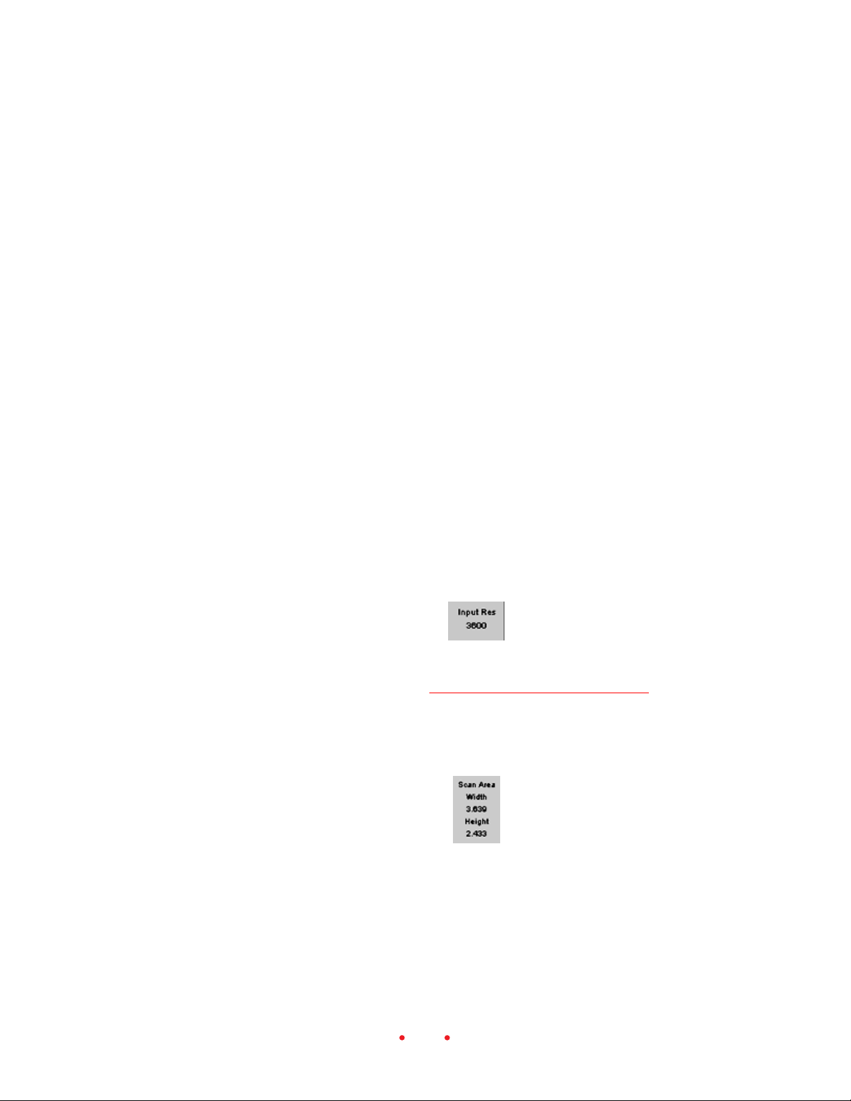
To save these settings, enter a name for the current settings on the dialog
box that appears. This feature allows you to create custom settings (for
example “Winter Outdoors”) for specific or unique shooting conditions.
You then retrieve one of your saved settings from the drop-down list. You
can also retrieve the original settings shipped with the scanner by choosing
Default from the drop-down list. Finally, you can also delete existing scan
profiles as needed while working on this dialog box.
This feature is useful for saving and recalling settings while working on
different filmstrips or slides across work sessions.
It may also be helpful to save settings during the same work session while
working on a single filmstrip or slide. You can use this feature to save a
variety of interim setups as you work with one image; when you decide on
the “best” settings from those you have saved, recall and use those for the scan.
Then you can use the Delete feature to delete your interim setups.
You can also use this feature while working your way through scans on one
filmstrip; you can establish and save a base set of controls for the whole
filmstrip. Then for different images on the filmstrip, recall that base set,
make necessary alterations and scan.
Scan Resolution
This field, to the right of the image, displays the scan resolution, a value
from 72 to 3600 dpi. Refer the Output Size and Input Values for more
detailed information.
Scan Area
This area displays the current width and height of the area of the frame to
be scanned. If a crop box appears, its dimensions are reflected here; otherwise it’s the full frame size. The units of measurement — centimeters,
inches, or pixels — for these values are displayed at the intersection of the
72
Page 73

rulers at the top left corner of the preview image on the Settings tab.
Change that unit as desired by clicking on the units button at the intersection of the rulers.
Refer to Output Size and Input Values for more detailed information on
Scan Area.
COLOR BALANCE TAB
The Color Balance tab displays a Before and an After version of the current
image, as well as slider controls.
When you enter this tab, the Before and After versions of the image are
identical. Then, as you make changes while viewing this tab, the Before
image remains unchanged, but the After image shows the results of the
changes. The After image reflects changes from controls on this tab, as well
as changes made with controls on the right of the screen outside of the
tabbed area (White, Gray and/or Black pointers, zooming, flipping, rotat-
73
Page 74

ing, and so on). When using the White, Gray, and/or Black pointers you
can click only on the After image.
When you leave this tab, the image in the After position becomes the updated image on all screens.
Brightness, Contrast, Saturation, Cyan/Red, Magenta/Green,
and Yellow/Blue
You can make adjustments on this tab for Brightness, Contrast, Saturation,
Cyan/Red, Magenta/Green, and Yellow/Blue. Adjust these controls by
dragging their sliders or by entering an integer from -100 to +100 into the
field next to the slider. The numbers represent percentage values; the
minimum value is -100% and the maximum value is +100%.
Reset
Click the Reset button to undo color balance adjustments made to the
image with the sliders during the current visit to this tab. When you click
this button, the After image is replaced with the image it displayed when
you entered this tab.
The Undo button functions differently from this Reset button. If you make
multiple changes to the sliders on this tab, the Undo button reverses only
the last slider change while the Reset button will undo all slider changes
you’ve made since entering this tab.
74
Page 75

LEVELS & CURVES TAB
The Levels & Curves tab provides access to the more advanced tone curve
and histogram functions, and displays a Before and an After version of the
current image.
When you enter this tab, the Before and After versions of the image are
identical. Then, as you make changes while viewing this tab, the Before
image remains unchanged, but the After image shows the results of the
changes. The After image reflects changes from controls on this tab, as well
as changes made with controls on the right of the screen outside of the
tabbed area (White, Gray and/or Black pointers, zooming, flipping, rotating, and so on). When using the White, Gray, and/or Black pointers you
can click only on the After image.
When you leave this tab, the image in the After position becomes the updated image on all screens.
75
Page 76

Channel, Histogram, and Curves
These functions behave consistently with their implementations in
Photoshop version 5.0 and later.
Adjustments to the curve and the use of the White, Gray, and/or Black
pointer buttons and Auto Balance functions cause the histogram to change;
but changes to the histogram do not cause the curve to change.
The X- and Y-axis tone curves are based on brightness, with shadows at 0%
and highlights at 100%. You create up to 4 new points on the tone curve
by:
Clicking in the grid.
Command-clicking (Macintosh) or control-clicking (Windows) on the
desired position on the Before image. The brightness value for the pixel
you’ve clicked appears on the curve at that input brightness level.
Points on the curve are fixed until you move or delete them. Move a point
by dragging it to a new location; delete a point by dragging it off the side of
the curve.
Make the appropriate Channel choice to perform the histogram and curve
functions on All colors, or separately on the Red, Green, or Blue channel.
(If you are working in CMYK, these channel values are still shown in RGB.)
In the histogram, above the Input and Output sliders, the x-axis range
contains values from 0-255, and the y-axis is the relative number of pixels
with each of these values. Suppose you had an image that was “flat” in
color, but nicely exposed; you would have a histogram with a hump in the
middle. Perhaps the lowest value on x-axis is 40 and the highest is 200,
indicating that the image does not have a lot of dynamic range.
You can now use the Input and Output sliders to increase your contrast
range to a full range of values as follows:
Drag the white slider on the Input scale to the position where the hump
in the curve in this example ends at 200 on the x-axis. This causes the
software to take the values at 200 and remap them to a new value of
255. This action remaps all the values from 40-200 to a new range of 40-
255.
76
Page 77

Reset
Now drag the black slider on the Input scale to 40, the other end of the
hump in this example. This remaps 40 to the value 0.
You now have an image that has the full range the system can display, all 8
bits from 0-255.
The opposite actions are true for the Output sliders. If you drag them in,
you decrease your contrast because you are no longer using the full output
range of your output device.
Click the Reset button to undo all levels and curve adjustments made to the
image during the current visit to this tab. When you click this button, the
After image is replaced with the image it displayed when you entered this
tab.
The Undo button functions differently from this Reset button. If you make
multiple changes to the levels and curve on this tab, the Undo button
reverses only the last change while the Reset button will undo all levels and
curve changes you’ve made since entering this tab.
WORKING WITH MULTIPLE SELECTED IMAGES
This section explains the action of the scanning software when you work
with multiple selected images.
Selecting Multiple Images
First we’ll describe how to select multiple images; after completing the
steps below, a red border will appear around each of the thumbnails of all
selected images. If you select multiple images, the last thumbnail you click
is displayed in the main image area.
You can select contiguous or noncontinuous frames by following standard selection methods for your operating system (PC or Macintosh).
As you do, you can use the Scroll Left and Scroll Right buttons to move
additional thumbnails into view before selecting additional frames.
You can deselect a single image by clicking on another thumbnail.
77
Page 78

You can deselect multiple images by clicking on another thumbnail.
Scanning Multiple Images
If you select multiple images and then scanned them, the settings you have
previously established for each image are applied individually to each of
those images during the scan. Therefore you can select a single image and
establish its settings, select another image and establish its settings, and so
on. Then you can select all of these images at one time and scan them in
one operation; each image will have its own settings applied.
NOTE: When discussing ‘settings’ here, we mean all parameters in the
tabbed areas as well as the parameters outside of the tabbed area, except for
Film Type, Profiles, Color Depth and Sharpening on the Settings tab.
As you change settings, the results of those changes are visible in the image
area; thumbnails are not updated (except for rotating and flipping).
You can also select multiple images and establish settings in one step to be
applied to all of the images; these common settings are retained individually for each of the selected images, just as if you had selected them one-byone and given each the same settings. You can then select another group of
images and establish common settings for them. Then, if you select some of
the images from the first group and some from the second group, and then
scan the images in one operation, the software applies the separate settings
you have established for each image.
When multiple frames are selected, the values displayed on the screen are
those for the frame shown in the image area. Since each selected image may
have different settings, the screen settings may not be the settings applied
to all selected images.
Finally, if you click the Exit button on the dialog box when scanning multiple images, the scanning is completed for the current film frame, scanned
images completed to this point are retained, and then the scanning is
cancelled for any remaining frames.
78
Page 79

Software License Agreement
EASTMAN KODAK COMPANY
WE ASSUME YOU HAVE CAREFULLY READ THE FOLLOWING TERMS
AND CONDITIONS DURING SOFTWARE INSTALLATION AND USE
OF THIS FILM SCANNER.
Eastman Kodak Company (Kodak) provides this software and licenses its
use worldwide.
You assume responsibility for selection of the software to achieve your
intended results, and for installation, use, and results obtained from the
software.
LICENSE
You may:
a. use the software;
b. copy the software onto one or more computers only for the purpose of
operating the equipment with which this software was provided (the
“Related Equipment”) or into any machine-readable form for backup
purposes in support of your use of the software;
c. transfer the software and license to another party to whom you also
transfer the Related Equipment, if the other party agrees to accept the
terms and conditions of this Agreement. If you transfer the software,
you must at the same time either transfer all copies to the same party or
destroy any copies not transferred.
79
Page 80

You must reproduce and include the copyright notice on any copy of the
software.
YOU MAY NOT USE, COPY OR TRANSFER THE SOFTWARE, OR ANY
COPY, IN WHOLE OR IN PART, EXCEPT AS EXPRESSLY PROVIDED
FOR IN THIS LICENSE.
IF YOU TRANSFER POSSESSION OF THE RELATED EQUIPMENT OR
ANY COPY OF THE SOFTWARE TO ANOTHER PARTY, YOUR LICENSE
IS AUTOMATICALLY TERMINATED.
TERM
The license is effective until terminated. You may terminate it at any time
by destroying the software together with all copies in any form. It will also
terminate upon conditions set forth elsewhere in the Agreement or if you
fail to comply with any term or condition of this Agreement. You agree
upon such termination to destroy the software together with all copies in
any form.
LIMITED WARRANTY
Kodak warrants the CD on which the software is furnished to be free from
defects in materials and workmanship under normal use for a period of
ninety (90) days from the date of delivery to you as evidenced by a copy of
your receipt.
Kodak does not warrant that the functions contained in the software will
meet your requirements or that the operation of the software will be uninterrupted or error free.
THE SOFTWARE IS PROVIDED ‘AS IS’ WITHOUT WARRANTY OF ANY
KIND, EITHER EXPRESSED OR IMPLIED, INCLUDING, BUT NOT
LIMITED TO, THE IMPLIED WARRANTIES OF MERCHANTABILITY
AND FITNESS FOR A PARTICULAR PURPOSE. THE ENTIRE RISK AS
TO QUALITY AND PERFORMANCE OF THE SOFTWARE IS WITH
YOU. IF THE SOFTWARE PROVES DEFECTIVE, YOU (AND NOT
80
Page 81

KODAK OR YOUR DEALER) ASSUME THE ENTIRE COST OF ALL
NECESSARY SERVICING, REPAIR, OR CORRECTION.
Some states do not allow the exclusion of implied warranties, so the above
exclusion may not apply to you. This warranty gives you specific legal
rights and you may also have other rights that vary from state to state.
LIMITATIONS OF REMEDIES
Kodak’s entire liability and your exclusive remedy shall be:
1. the replacement of any CD not meeting Kodak’s “Limited Warranty”
that is returned to Kodak or your dealer with a copy of your receipt, or
2. if Kodak or the dealer is unable to deliver a replacement CD that is free
of defects in materials or workmanship, you may terminate this Agreement by returning the software.
IN NO EVENT WILL KODAK BE LIABLE TO YOU FOR ANY DAMAGES,
INCLUDING ANY LOST PROFITS, LOST SAVINGS, OR OTHER INCIDENTAL OR CONSEQUENTIAL DAMAGES ARISING OUT OF THE USE
OR INABILITY TO USE THE SOFTWARE EVEN IF KODAK OR YOUR
DEALER HAS BEEN ADVISED OF THE POSSIBILITY OF SUCH DAMAGES, OR FOR ANY CLAIM BY ANY OTHER PARTY.
Some states do not allow the limitation or exclusion of liability for incidental or consequential damages, so the above limitation or exclusion may not
apply to you.
GENERAL
You may not sublicense, assign, or transfer the license or the software,
except as expressly provided in this Agreement. Any attempt otherwise to
sublicense, assign, or transfer any of the rights, duties, or obligations
hereunder is prohibited.
This Agreement will be governed by the laws of the State of New York.
Should you have any questions concerning this Agreement, contact Kodak
at 1-800-CD-KODAK (1-800-235-6325).
81
Page 82

YOU ACKNOWLEDGE THAT YOU HAVE READ THIS AGREEMENT,
UNDERSTAND IT, AND AGREE TO BE BOUND BY ITS TERMS AND
CONDITIONS. YOU FURTHER AGREE THAT IT IS THE COMPLETE
AND EXCLUSIVE STATEMENT OF THE AGREEMENT BETWEEN US,
WHICH SUPERSEDES ANY PROPOSAL OR PRIOR AGREEMENT, ORAL
OR WRITTEN, AND ANY OTHER COMMUNICATIONS BETWEEN US
RELATING TO THE SUBJECT MATTER OF THIS AGREEMENT.
82
Page 83

Warranty
THIS WARRANTY IS LIMITED TO THE UNITED STATES. THIS WARRANTY APPLIES ONLY FOR SERVICING EQUIPMENT ORIGINALLY
PURCHASED IN THE UNITED STATES.
WARRANTY TIME PERIOD
Kodak warrants your KODAK PROFESSIONAL RFS 3600 Film Scanner to
be free from malfunctions and defects in both materials and workmanship
for 12 months from the date of purchase.
WARRANTY REPAIR COVERAGE
If this equipment does not function properly during the warranty period,
due to defects in materials or workmanship, Kodak will at its option, either
repair or replace the equipment, without charge, subject to the conditions
and limitations stated herein. Such repair service will include all labor as
well as any necessary adjustments and/or replacement parts in order to
maintain the equipment in an operating condition consistent with Kodak’s
specifications. Kodak will also provide telephone assistance during the
warranty period.
Unless a specific Kodak warranty is communicated to the purchaser in
writing by a Kodak company, no other warranty or liability exists beyond
the information contained above, even though defect, damage or loss may
be by negligence or other act.
If replacement parts are used in making repairs, these parts may be
remanufactured, or may contain remanufactured materials. If it is neces-
83
Page 84

sary to replace the entire system, it may be replaced with a remanufactured
system. If it should become necessary to repair or replace a malfunctioning
or defective system, the provisions of this warranty shall apply to the repaired or replaced system until 30 days from the date of return, or until the
end of the original 12 month warranty period, whichever is later.
Please save your proof of purchase (sales receipt) as Kodak reserves the
right to confirm the date of purchase BEFORE permitting any repairs to be
made.
OUTSIDE THE UNITED STATES
In countries other than the United States, terms of this warranty may be
different. Unless a specific Kodak warranty is communicated to the purchaser in writing by a Kodak company, no other warranty or liability exists
beyond the information contained above, even though defect, damage or
loss may be by negligence or other act.
HOW TO OBTAIN SERVICE
In the United States, call Kodak at 1-800-CD-KODAK (1-800-235-6325).
In Canada call 1-800-465-6325.
In other countries, call your nearest Kodak representative.
If service is required, your Kodak representative will instruct you to return
the unit to the nearest service center for repair and will issue a return
authorization number. You will be responsible for providing dated proof of
purchase to verify warranty coverage.
DO NOT RETURN ANY DEFECTIVE EQUIPMENT TO KODAK WITHOUT PRIOR AUTHORIZATION FROM KODAK.
When shipping the KODAK PROFESSIONAL RFS 3600 Film Scanner, the
defective equipment shall be packed in its original packing material and
shipping is the customer’s responsibility. If the original packing material is
unavailable, then repacking will be at the owner’s expense. The owner is
84
Page 85

responsible for the shipping charges to Kodak, and Kodak is responsible for
the return shipping charges. (Refer to Repacking Instructions for additional information.)
Repair turnaround is anticipated to be approximately five working days
from receipt of the unit at a service center.
LIMITATIONS
This warranty does not cover circumstances beyond Kodak’s control;
service or parts to correct problems resulting from the use of attachments,
accessories or alterations not marketed by Kodak; service required as a
result of relocation; unauthorized modifications or service; failure to pack
your scanner according to repacking instructions; misuse, abuse, or failure
to follow Kodak’s operating instructions; failure to use Kodak-supplied
items.
KODAK MAKES NO OTHER WARRANTIES, EXPRESS, IMPLIED, OR OF
MERCHANTABILITY OF THIS EQUIPMENT. Repair or replacement
without charge are Kodak’s only obligation under this agreement.
Kodak will not be responsible for any consequential or incidental damages
resulting from the purchase, lease, use, or improper functioning of this
equipment, even if loss or damage is caused by the negligence or other fault
of Kodak.
Such damages for which Kodak will not be responsible include, but are not
limited to, loss of revenue or profit, downtime costs, loss of use of the
equipment, cost of any substitute equipment, facilities or services or claims
of your customers for such damages.
This limitation of liability will not apply to claims for injury to persons or
damage to property caused by the sole negligence or fault of Kodak or by
persons under its direction or control.
EASTMAN KODAK COMPANY
KODAK Professional Imaging
Global Customer Service & Support
85
Page 86

Troubleshooting
HARDWARE
There is no power to the scanner; the status light on the top of the scanner is
not on.
Make sure all plugs are securely seated. Make sure the scanner power
button is on at the rear of the scanner. Try another power outlet.
Your computer will not start properly. You have just connected the scanner (or
you have just connected another SCSI device to the computer).
If you are using the SCSI connection, there may be a SCSI ID conflict.
All SCSI devices connected to the computer must have unique ID numbers. Refer to Connecting the Scanner to Your Computer, and reset the
SCSI ID on the scanner as described there (or reset the SCSI ID on the
newly connected device).
Your SCSI cables may be too long. The total length of all SCSI cables in
the chain must be less than 15 feet (4.6 meters).
A filmstrip with a splice in it will not move properly through the scanner.
Spliced film is not supported, and should not be used with the scanner.
The USB connection on a PC-Compatible is not working.
Follow the steps in Making a USB Connection to ensure that your
computer system is locating the scanner.
The green LED at the top right of the scanner flashes in an unending, repeated
pattern.
A problem has been detected with the scanner; turn off your computer
system and scanner, and restart.
86
Page 87

SOFTWARE
The scanner window does not open.
Be certain the software has been installed as described in Installing
Scanner Software.
The scanner does not appear as a choice on the Photoshop File, Import menu
as expected.
Quit Photoshop. Run the installation program again, and click Repair.
Try again to reach the scanner software.
If the same problem occurs, quit Photoshop. Run the installation program, but this time click Remove. Run the installation program again,
which will reinstall the scanner software. Try again to reach the scanner
software.
The scanner software does not work properly the first time you try it on a PCcompatible, and you are using the SCSI connection.
Be certain that you have installed the Windows ASPI files that accompany your ASPI compliant SCSI host adapter. The scanner software will
not work properly unless these files have been installed. This software is
intended for use with applications that are ASPI compliant for Windows, and not for use with applications that are ASPI compliant for
other operating platforms.
IMAGE
You are scanning multiple selected images, and the results of color balancing
are not as expected for each image.
Refer to the section Working with Multiple Selected Images for an
explanation of the effect of color balancing when scanning multiple
selected images.
87
Page 88

The image appears blank after scanning.
An unexposed portion of a 35 mm filmstrip is being scanned; move the
filmstrip in the scanner and try again.
Or the Contrast slider on the Color Balance tab is set so that the image
cannot be seen.
Or the histogram sliders on the Levels & Curves tab are set so that the
image cannot be seen.
The previewed or scanned image is not properly centered, or parts of two
images are obtained.
Shift the film in the scanner in small increments until it is properly
positioned. To accomplish this, tap the Reverse or Forward buttons on
top of the scanner, or option-click (Macintosh) or control-click (Windows) the Reverse or Forward buttons in the scanner software.
Images scanned from slides are not focused properly.
Assuming the camera was focused properly when the film was exposed,
you can use the scanner focus control to focus on a slide. Since the
thickness of slide mounts can vary, this feature is needed to determine
the correct plane of the film in the scanner. Click the Auto-Focus Slide
button once to perform auto-focus.
If the focus is still not correct, click the Focus button again; a dialog
box appears asking if you want to perform a manual focus adjustment.
If you click no, auto-focus is performed again. If you click yes, you see a
dialog box that shows the current focus position. You can now change
the focus position (an integer from 1 to 30), by entering another focus
value. For example, if the dialog box displays the value 17, you might
try changing the focus in one step increments, in this case by changing
it to 16 or to 18.
The previewed image is the negative of the actual image.
An incorrect film type is selected; choose the correct data from the Film
Type area of the Settings tab.
88
Page 89

Only a small portion of the full image was acquired in the scan.
The crop rectangle is in place over the preview image; remove the crop
box by click outside of the crop box on the preview image.
Other image problems occur.
Light in the area of the scanner is interfering with scanner operation.
Do not have a high level of direct light around the scanning area.
The contrast of your scanned images with consistently too-high or too-low in
Adobe Photoshop.
The monitor gamma may not be calibrated properly; calibrate it per
instructions in your Photoshop manual.
89
Page 90

Messages
A Base File Name of base filename does not follow the operating system rules
for naming files. Many special characters, such as * and @, may not be used in
a filename. Please refer to the operating system’s rules for naming files, change
the Base File Name, and try saving the images to files again.
You have used improper characters in the scan profile filename. Try
again with a filename that meets requirements for your operating system.
Or the filename does not meet other requirements of the operating
system, for example it is too long.
A final scan has not been performed on the Prescanned frames. Do you really
want to close the film scanner software?
Make an appropriate choice, to continue your scanning activity or to
close the software, from the dialog box.
A Preview scan has not been performed. Do you want to continue with the
final scan?
Make an appropriate choice, to perform the scan or to cancel, from the
dialog box.
A Scan Profile already exists with that name. Do you want to replace the
existing profile?
Make an appropriate choice.
A Scan Profile name of filename does not follow the operating system rules for
naming files. Many special characters, such as * and @, may not be used in a
filename. Please refer to the operating system’s rules for naming files, change
the Scan Profile name, and try saving the scan profile again.
You have used improper characters in the scan profile filename. Try
again with a filename without any of those characters.
90
Page 91

Are you sure you want to delete the scan profile name Scan Profile?
Use this confirmation dialog box to indicate whether or not you wish to
delete the scan profile.
Auto-focus has already been performed on this slide. Select Auto to perform
auto-focus again, or select Manual to fine tune the existing focus.
For a detailed explanation of the Auto-Focus Slide button, refer to
Reference – Software (Auto-Focus Slide).
Based on your Output and Magnification values, the Scan [Height/Width] is
larger than a 35mm frame. Therefore, the Scan [Height/Width] will be set to
the maximum, the Scan [Width/Height] will be adjusted to maintain the
locked aspect ratio. This also requires the Magnification and Output Resolution to be adjusted.
For a detailed explanation of these relationships, refer to Reference –
Software (Output Size and Input Values).
Based on your Output and Magnification values, the Scan Resolution would
need to be #### dip, which is [higher than the maximum 3600 dpi/lower than
the minimum 72 dpi]. The Scan Resolution will be set to 3600dpi/72dpi] and
the Output Resolution will be set to #### dpi.
For a detailed explanation of these relationships, refer to Reference –
Software (Output Size and Input Values).
Do you want to cancel the [Prescan/Final Scan] currently in progress?
Make an appropriate choice, to stop scanning after the current frame
and retain all scans to this point, or to continue scanning.
If Output Width & Height are not locked: Based on your Output and Magnification values, the Scan [Height/Width] is larger than a 35mm frame. Therefore, the Scan [Height/Width] will be set to the maximum and the Output
[height/width] will be adjusted.
If Output Width & Height are locked: Based on your Output and Magnification values, the Scan [Height/Width] is larger than a 35mm frame. Therefore,
the Scan [Height/Width] will be set to the maximum, the Scan [Width/
91
Page 92

Height] will be adjusted to maintain the locked aspect ratio, and the Magnification will be adjusted.
For a detailed explanation of these relationships, refer to Reference –
Software (Output Size and Input Values).
Scanning frame ##. NOTE: ## is the sequence number of the frame and not
the frame number from the film strip.
This message appears when you are scanning a frame or frames. If you
cancel from this message, the current scan is completed, and completed
scans to this point are retained.
The Black Balance value must be between 0 and 255, inclusive.
You have entered a balance value that is outside of the range. As
prompted, try again with a value from 0 to 255.
The directory directory name does not exist. Would you like to create it?
The directory specified in the Save to File dialog box does not exist.
Indicate that you want to create a new directory with this name, or
cancel the save and indicate a new directory.
The directory directory name is inaccessible. Please review and change the
directory name, or use the Browse function to search for and select a directory.
There is a problem with the directory specified in the Save to File dialog
box. As indicated enter a new name or use specify a new directory via
the Browse button.
The file directory and file name already exists. Do you want to replace the
existing file?
You have specified the directory and filename of an existing file. Make
the appropriate choice.
The film scanner is unable to transfer scanned image data to software title.
Please verify that software title is running and select OK to continue. Or select
Cancel to discard the image data and stop any remaining film scanning.
This message appears when the scanner software is running and the film
scanner is scanning film, but the host software (typically Photoshop)
has closed, not permitting the scanned image data to be transferred to
the host software. Make the appropriate choice.
92
Page 93

The film scanner is warming up. Please wait.
Wait as indicated.
The Film Type was changed after the Prescan. You may want to perform a
Prescan Frame or Prescan Strip to update the prescan images. But, this will
discard all other image adjustments you have made while previewing the
current images.
As indicated, you have changed the Film Type setting after performing a
prescan. If you have already performed image adjustments based on the
previous Film Type, they are probably incorrect and you may wish to
perform a prescan and then begin image adjustment again.
The Output Resolution must be between 72 dpi and 7200 dpi inclusive. The
value you entered is too [low/high] and will be automatically set to [72/7200]
dpi.
The output resolution you have entered is not within the range of the
scanner software. As indicated, a value from the closest end of the range
will be substituted. If that is not your intention, enter another value
within range of the scanner software.
The resolution of your monitor is too low. Increase the resolution by choosing
Start > Settings > Control Panel > Display > Settings tab. Move the Screen
Area slider to at least 800 x 600 pixels and select the OK button. Then retry
accessing the film scanner.
PC-compatible only. As indicated the monitor resolution is too low to
run the scanner software. Change the resolution as described and try
again.
The resolution of your monitor is too low. Increase the resolution by going to
the Apple Menu, selecting Control Panels and then Monitors & Sound. Click
the Resolution icon and in the Resolution listing, select a resolution setting
which is at least 800 x 600 pixels. Close the Multiple Scan Display panel and
then retry accessing the film scanner.
Macintosh only. As indicated the monitor resolution is too low to run
the scanner software. Change the resolution as described and try again.
93
Page 94

The value you entered is too [low/high]. The value must be between 0 and
255.
Try again, but this time enter a white or black balance value from 0
to␣ 255.
The value you entered is too low/high. The value must be between -100% and
+100%.
Try again, but this time enter a value from -100 to +100.
The White Balance value must be between 0 and 255, inclusive.
You have entered a balance value that is outside of the range. As
prompted, try again with a value from 0 to 255.
Unable to access ICC Profile [profile name]. Close and restart the scanner
software, and try again. If the problem persists, try another ICC Profile or, if
you must use this ICC Profile, reinstall the scanner software and try again.
There is a problem with the ICC profile. If the file was installed with the
scanner software, quit Photoshop, then run the installation program
again, and click Repair. Try the software again.
If the same problem occurs, quit Photoshop again. Run the installation
program, but this time click Remove. Then run the installation program
again, which will reinstall the scanner software. Try the software again.
If you obtained the file from another source, such as through a download from the web, obtain and reinstall a fresh copy of that file.
Unable to communicate with the RFS 3600 Film Scanner. Try the following:
Make sure the scanner power is on
Check all cables
With a SCSI connection (not USB), check for a SCSI ID conflict or improper termination of the SCSI chain. Refer to the User’s Manual on the
CD as needed.
For assistance with a SCSI connection refer to Making a SCSI Connec-
tion in this manual.
94
Page 95

Unable to display the User’s Manual. Please install Adobe Acrobat Reader
from the CD or directly from Adobe’s web site, and try accessing the User’s
Manual again.
Install Adobe Acrobat reader, and try again.
Unable to open Film Term [film term name]. Close and restart the scanner
software, and try again. If the problem persists, try another Film Term or, if
you must use this Film Term, reinstall the scanner software and try again.
There is a problem with the Film Term file. Run the installation program again, and click Repair. Try again to reach the scanner software.
If the same problem occurs, quit Photoshop. Run the installation program, but this time click Remove. Run the installation program again,
which will reinstall the scanner software. Try again to reach the scanner
software.
Unable to open Scan Profile [profile name]. You may try again or, if possible,
recreate these scanning parameters and save the Scan Profile again.
There is a problem with file you are trying to open. As suggested, you
may need to recreate the scan settings if possible and save the setting
again.
Unable to transfer image data from the film scanner to the computer. Try the
following:
Make sure the scanner power is on
Check all cables
With a SCSI connection (not USB), check for a SCSI ID conflict or improper termination of the SCSI chain. Refer to the User’s Manual on the
CD as needed.
For assistance with a SCSI connection refer to Making a SCSI Connec-
tion in this manual.
95
Page 96

Updating the
KODAK␣ Driver
This appendix provides information on obtaining and installing updated
scanner software including:
Directions for downloading the software electronically. We recommend
this as the preferred method of obtaining driver updates.
Directions for installing the updated software.
DOWNLOADING SOFTWARE DRIVERS
ELECTRONICALLY
The availability of software downloading service described in this section
may vary from area to area.
When Kodak prepares updated versions of the scanner software (for example new scanner software, new firmware control programming for the
scanner, or new film terms to support new film releases), it makes those
updates available electronically. Downloading an update is the quickest
way to obtain the most current software. You receive the software immediately, and at your convenience. However, it is your responsibility to check
the web site for updates.
Downloading a driver requires communications access, for example a
modem, communications software, and a telephone line - items not supplied by Kodak.
You access updated software at the Kodak web site at:
http://www.kodak.com/go/professional
96
Page 97

That page contains links to software updates listed by product type. Find
and download the scanner software by following the appropriate links.
Once you have obtained the software, continue below.
INSTALLING AND UPDATING SOFTWARE/
FIRMWARE
1. Double-click on the icon of the file you have downloaded and follow
the directions that appear.
2. Refer to the Reference – Software (About/Version Numbers and Firm-
ware Upgrade) for directions on completing a firmware update of the
scanner.
97
Page 98

Repacking Instructions
If you are having difficulties using your KODAK PROFESSIONAL RFS
3600 Film Scanner, please contact a Kodak representative before returning
your unit for service. In the United States, call Kodak at 1-800-CD-KODAK
(1-800-235-6325). In Canada call 1-800-465-6325. In other countries, call
your nearest Kodak representative. If service is required, your Kodak representative will tell you how to return the unit to the nearest service center
for repair and will issue a return authorization number.
Please make sure that you have filled out and returned your Warranty
Registration card; warranty service will not be provided without return of
the Warranty Registration card or dated proof of purchase.
Please follow these instructions if you need to repack your scanner to ship
it to Kodak.
1. Prepare a written enclosure including: your name, complete address,
telephone number, email address, date, scanner serial number, return
authorization number, and a description of the problem you have
encounter in complete detail.
2. Shut down the computer and scanner.
3. Disconnect all cables from the scanner.
4. Place the scanner into a plastic bag, seal the bag, and place it into the
original shipping carton. The plastic bag is important because it protects the Scanner from dirt and scuffing during shipment. If the original
packing materials have been discarded or are not available, you must
provide the packing materials at your expense.
5. Pack all remaining items that shipped with the scanner – the AC
adapter, all cables, and the scanner CD-ROM – in the box with the
scanner.
6. Place your written enclosure into the carton.
7. Close and seal the shipping carton with tape.
8. Ship to Kodak as instructed by your Kodak representative.
98
Page 99

Specifications
FILM
Filmstrip and Slides
Accepts 35 mm filmstrips, 3 to 36 frames in length
Accepts single standard 35 mm slides from 1.0 to 3.5 mm in thickness
Scans color Negative, color Reversal (slide film), and B&W negative 35 mm
film
33
3
CAUTION: Never load a single or two-frame film negative. Additionally,
33
spliced film is not supported, and should not be used with the scanner.
Film Loading and Ejecting
Hand feed filmstrip from left of scanner with auto-advancing of filmstrip;
automatic ejection of filmstrip
Single slide inserted/removed by hand from front of scanner
Filmstrip Movement through Scanner
Software and hardware control of filmstrip movement through the scanner
on a frame-by-frame basis or in fine movements over a single frame
Software and hardware control to eject a filmstrip from scanner
Scan Area
36.5 mm width x 24.3 mm height
99
Page 100

SCANNER HARDWARE
Safety
Refer to the dataplate on the bottom of the scanner
Power
Refer to the dataplate on the AC adapter
Color Separation
CCD (charge coupled device) sensor
Light Source
Cold cathode fluorescent lamp
Computer Interface (USB and SCSI II)
Connects to either a PC-compatible or a Power Macintosh via either a SCSI
II or a USB connection as supported by the hardware and operating system
PC-compatible SCSI connection requires supported SCSI host adapter
cards and software
Switch selectable SCSI termination
Operating Buttons
Filmstrip movement with three buttons: Eject, Reverse, and Forward
Scan of image in scanning position with Scan
Approximate Dimensions
11.50 in. (29.2 cm) long x 7.75 in. (19.7 cm) wide x 4.25 in. (10.8 cm) high
Approximate Weight (Scanner alone)
3.4 lbs. (1.5 kg)
Operating Ambient Temperature Range
50° to 104°F (10° to 40°C)
Note: Do not turn on the Scanner unless it is within this range. If the
Scanner has been stored or transported outside of this range, allow it to
return to within this range before turning it on.
100
 Loading...