

Page 1

Operator's Manual A-62032
Part No. 3C4923
KODAK
IMAGELINK
TM
Printer 7
BUSINESS IMAGING SYSTEMS
Page 2
The
Kodak Imagelink
Paper Supply, CAT No. 859 1943, the
and the
with the following standards and bear therefore a CE mark:
following the provisions of the applicable directives:
Kodak Imagelink
Printer 7, CAT No. 887 9405, with the
Kodak Imagelink
Printer 7 Sorter Interface, CAT No. 199 7964, are in conformance
EN 55022 Class B/1987
EN 50082-1/1992
EN 60555-2/1987
EN 60950/1993
89/336/EEC and amendments
73/23/EEC and amendments.
Printer 7 Sorter, CAT No. 864 6754,
Kodak Imagelink
Printer 7
LE PRESENT APPAREIL NUMERIQUE N’EMET
PAS DE BRUITS READIOELECTRIQUES
DEPASSANT LES LIMITES APPLICABLES AUX
APPAREILS NUMERIQUES DE LE CLASSE A
PRESCRITES DANS LE REGLEMENT SUR LE
BROUILLAGE RADIOELECTRIQUE EDICTE
PAR LE MINISTERE DES COMMUNICATIONS
DU CANADA.
This equipment complies with the requirement in part 15 of FCC Rules for a class A
computing device. Operation of this equipment in a residential area may cause unacceptable
interference to radio and TV reception requiring the operator to take whatever steps may be
necessary to correct the interference.
(Canada only)
This digital apparatus does not exceed the Class A limits for radio noise emissions from
digital apparatus as set out in the interface - causing equipment standard entitled “Digital
Apparatus,” ICES - 003 of the Department of Communications.
THIS DIGITAL APPARATUS DOES NOT
EXCEED THE CLASS A LIMITS FOR RADIO
NOISE EMISSIONS FROM DIGITAL
APPARATUS AS SET OUT IN THE RADIO
INTERFERENCE REGULATIONS OF
THE CANADIAN DEPARTMENT OF
COMMUNICATIONS.
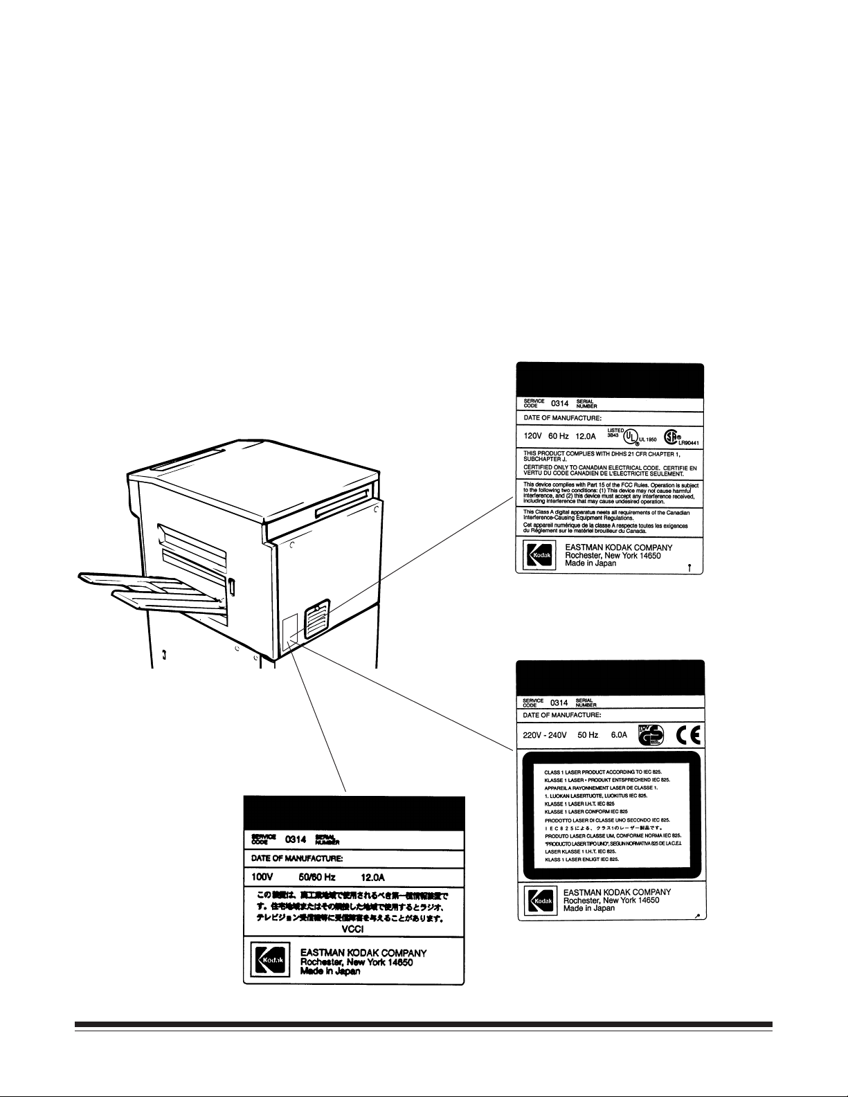
WARNING: The use of controls or adjustments or the performance of procedures other than
those specified in this publication may result in hazardous radiation exposure. This product
complies with 21 CFR, Chapter 1, Subchapter J, as indicated on the label located on the rear
cover of the printer.
A-62032 November 1996 i
Page 3
Warning and safety information
Locate the printer in a well-ventilated room.
A negligible amount of ozone is generated during
normal operation of this printer. An unpleasant
odor may, however, be created in poorly ventilated
rooms during extensive printer operations. For a
comfortable, healthy, and safe operating
environment, it is recommended that the room be
well-ventilated.
A dedicated electrical socket-outlet shall be
installed near the printer and shall be easily
accessible.
KODAK
IMAGELINKTM Printer 7
KODAK
IMAGELINKTM Printer 7
KODAK
IMAGELINKTM Printer 7
ii November 1996 A-62032
Page 4
Section 1 Overview
Introduction
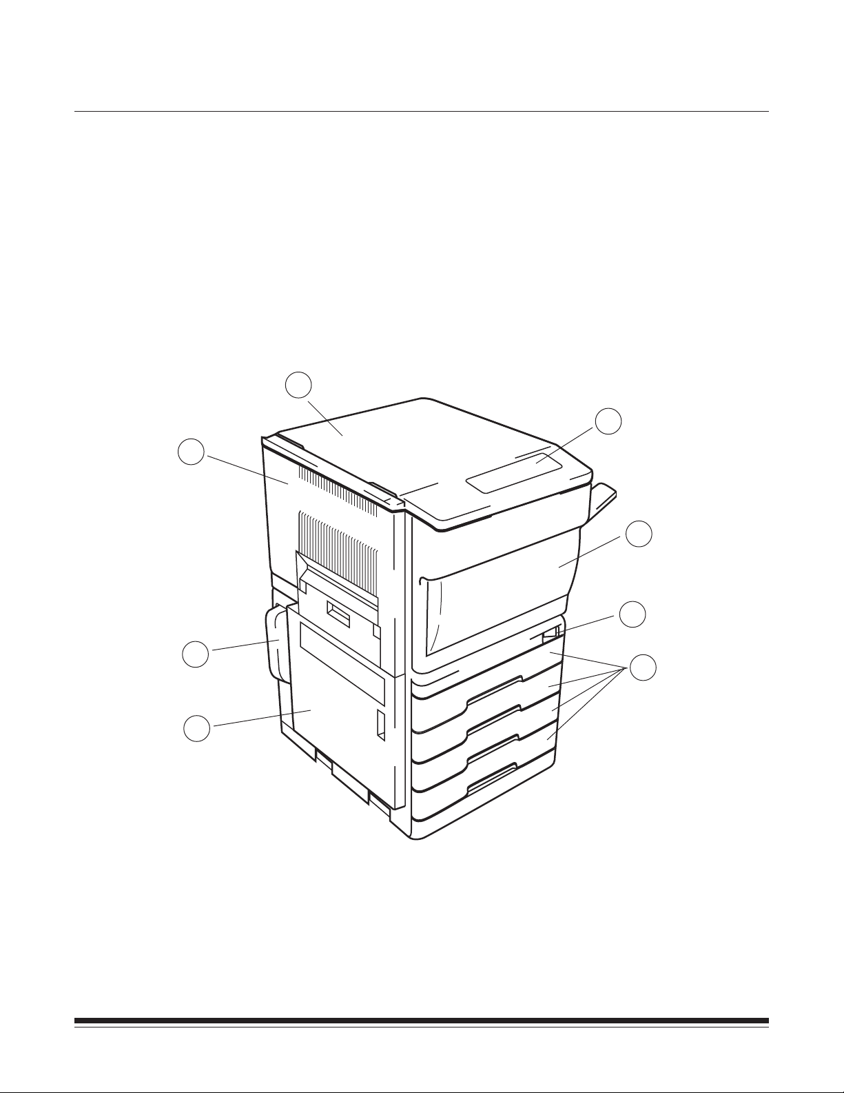
Location/Description of parts—Front
3
We are pleased that you have purchased the
Printer 7. We feel confident that you will find your new laser printer
more than adequate to meet your printing needs.
In order to make the best use of the printer, we recommend that
you read the information in this manual carefully and follow the
instructions contained herein. This manual, along with the
appropriate
Node manuals, provides information on operating the printer,
setting up the printer, operator maintenance, and instructions on
how to clear a jam.
4
Kodak Imagelink
Digital Workstation and Network
Kodak Imagelink
5
6
2
1
1. Paper Supply Cabinet Door
2. Toner Collection Bottle
3. Printer Left Cover
4. Printer Top Cover
5. Operation Panel (See page 2-1 for detailed
drawing.)
7
8
6. Printer Front Cover
7. Power ON/OFF Switch
8. Paper Cassette (Universal Cassette)
A-62032 November 1996 1-1
Page 5
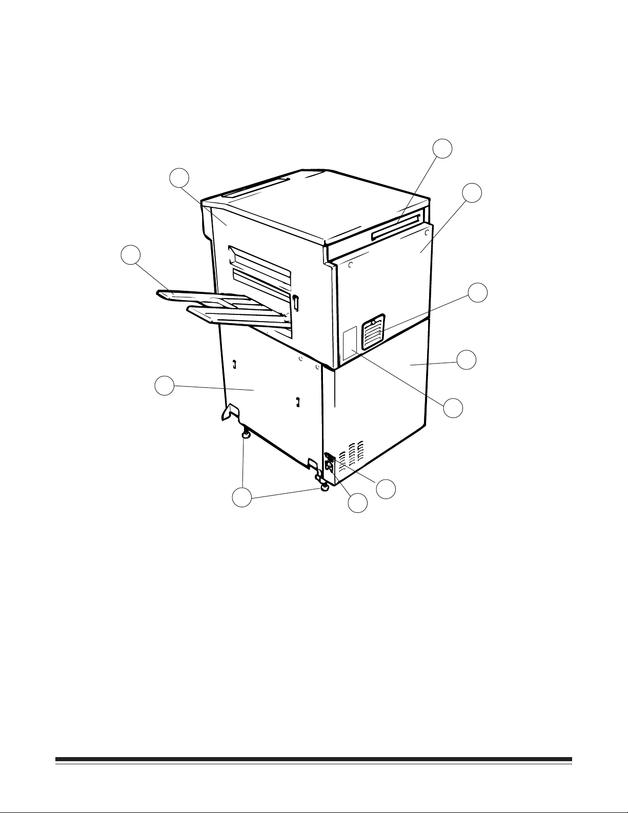
Location/Description of parts—Back
11
10
12
13
14
15
9
19
9. Paper Supply Cabinet Right Cover
10. Paper Exit Tray
11. Printer Right Cover
12. Printer Cable Interface Socket
13. Printer Rear Cover
14. Image Transfer/Paper Separator Ozone
Filter Cover
16
17
18
15. Paper Supply Cabinet Rear Cover
16. Dataplate
17. Circuit Breaker
18. Power Cord Socket
19. Adjustable Feet
1-2 November 1996 A-62032
Page 6
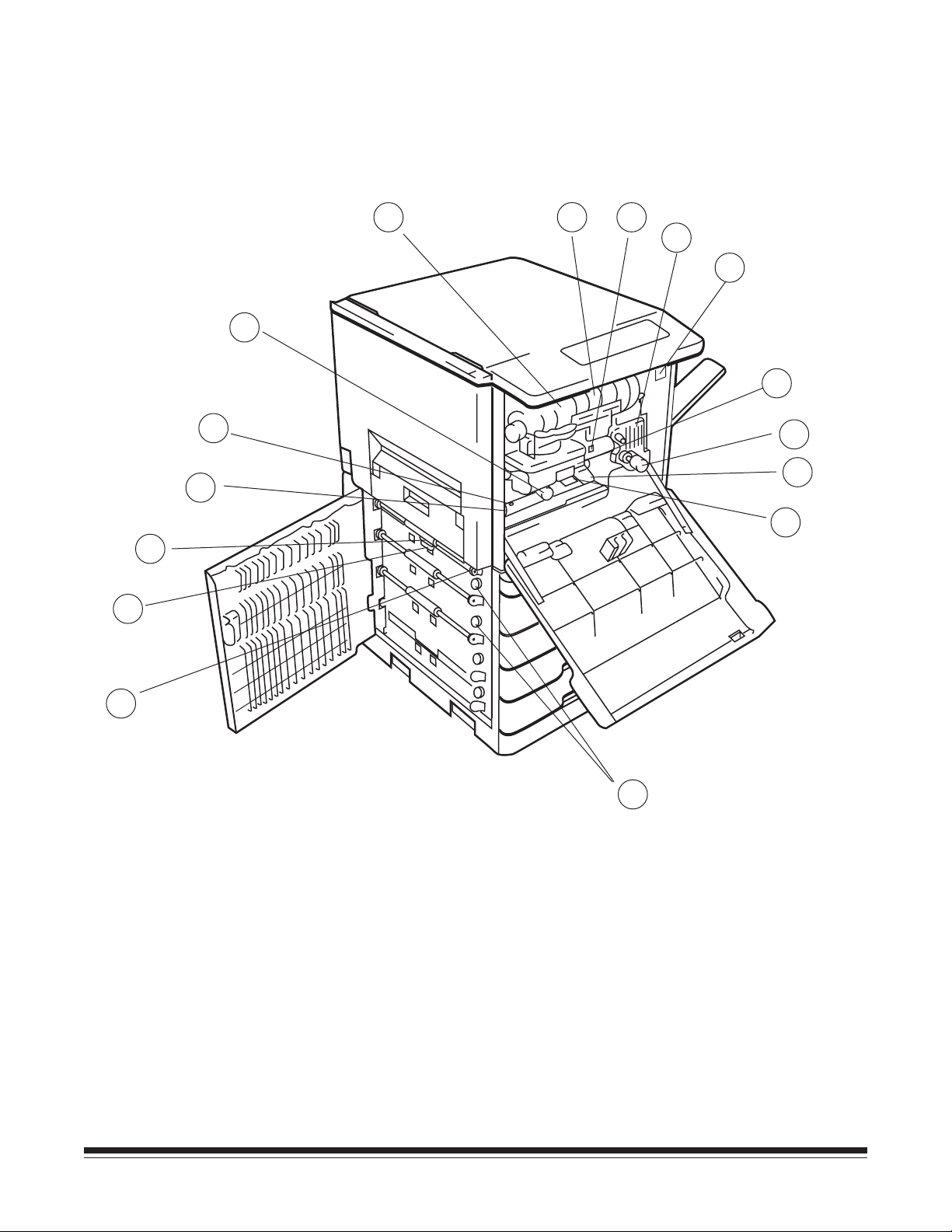
Location/Description of parts—Inside
21
22
23
24
25
26
27
28
29
30
31
32
33
34
20
20. Vertical Transport Roller Knob (M6)
21. Separator Roller
22. Feed Roller
23. Transport Roller Knob (M5)
24. Transport Section Release Plate (M4)
25. Synchronizing Roller Knob (M3)
26. Toner Bottle Holder
27. Toner Bottle
35
28. Drum Charge Ozone Filter
29. Fusing Unit
30. Mechanical Print Counter
31. Electrophotographic (EP) Unit
32. Fusing Roller Knob (M1)
33. Release Lever (M2)
34. Image Transfer/Paper Separator Charger
35. Paper Take-Up Section Release Knob
A-62032 November 1996 1-3
Page 7
Section 2 Operation
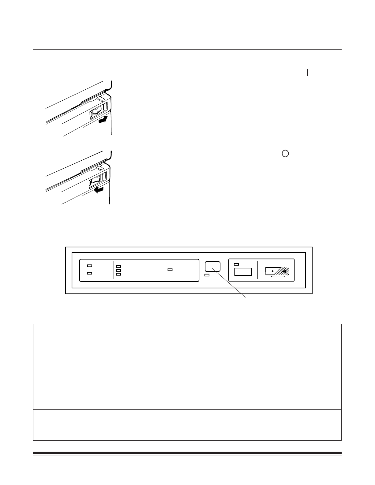
Turning the printer on and off
Operation panel
Check that the power cord has been connected to the printer and
outlet; turn the power ON/OFF switch to its right side ( side) to
turn the power on.
Turn the power ON/OFF switch to its left side ( side) to turn the
power off.
The operation panel contains the Printer Status and Error Code
displays, and the Test controls.
Printer Status
Ready
Busy
Paper Jam
READY
BUSY
PAPER JAM
TONER EMPTY
USED TONER BOTTLE FULL
Indicates
Printer able
to accept
new print
commands
Currently printing,
unable to accept
new print
commands
Clear paper jam
PAPER EMPTY
SELECTED
TRAY
Printer Status
Toner Empty
Used Toner
Bottle Full
Paper Empty
Selected
Tray
CHECK
Error Code Display
(2 characters appear,
see Appendix C)
Indicates
Replace with a
new Toner Bottle
Replace with a
new Used Toner
Collection Bottle
Paper cassette you
are using is empty,
refill paper.
TEST
CANCEL
Test Control
Test
Cancel
Functions
Press to start Test
Print function only
when the Ready
indicator is lit.
Press to cancel
Test Print
function.
A-62032 November 1996 2-1
Page 8
Loading paper
This laser printer supplies paper to the printer by feeding paper into
the unit automatically from one of four universal cassettes.
Universal cassette
The universal cassette can be used to feed the following paper
sizes: A3T, B4T, A4T/Y, A5T, B5T/Y, B6T, LedgerT, LegalT,
LetterT/Y, ExecutiveT/Y, InvoiceT, 7 x 8 1⁄2". (T means lengthwise
feeding and Y means crosswise feeding.) See Appendix A for more
information on paper sizes. 350 sheets of paper can be loaded in
each of the 4 universal cassettes.
NOTE: B5Y and B6T feed from upper 3 cassettes only.
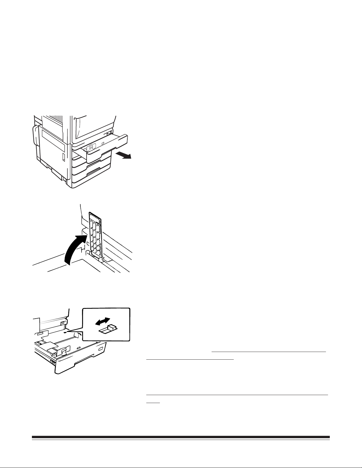
1. Pull the universal cassette out as far as it will go from the
cabinet.
Inch
Metric
USA only
Swing up the lift-up plate release lever to lower the paper lift-up
plate in the cassette.
2. Change the switch position located on the rear right side in
the cassette, depending on the paper size to be used.
Switch to “Metric” when paper size is A3T, B4T, A4T/Y,
B5T/Y, A5T, or B6T.*
All trays must be set to “Metric” if the
previous paper sizes are used.
Switch to “Inch” when paper size is 11 x 17" (LedgerT),
8-1/2 x 14" (LegalT), 8-1/2 x 11" (LetterT/Y), 7-1/4 x 10-1/2"
(ExecutiveT/Y), 5-1/2 x 8-1/2" (InvoiceT), or 7 x 8 1/2".*
All trays must be set to “Inch” if the previous paper sizes are
used.
*All trays must have the same size paper to use the Digital Workstation or
Network Node AUTO feature.
2-2 November 1996 A-62032
Page 9
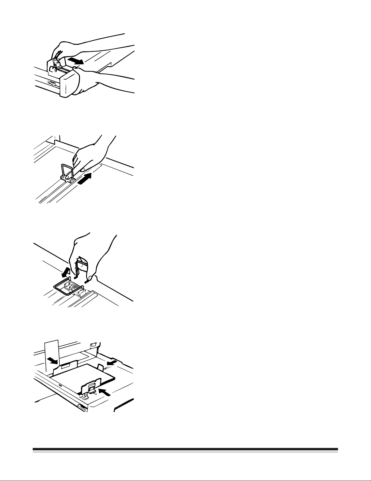
3. While holding the cassette, depress and spread the front paper
guide wider than the paper size to be used.
4. Slide the green resin plate of the right paper guide toward the
right side wider than the paper size to be used.
NOTE: Be sure to slide the resin plate and not to hold the lever
part, as that may bend it.
5. When you load the ledgerT size paper, slide the right paper
guide all the way to the right side and remove the lever by
depressing it from the both sides. And insert the edges of the
lever in the position shown in the illustration.
6. Align the stack of paper and set the paper in the cassette with
the sealed surface down. While holding the cassette, slide
and fit the front and right paper guides to the paper edges.
NOTE: Be sure to slide the resin plate to move the right paper
guide. Check that the top level of the paper does not
exceed the line marked on the rear paper guide.
A-62032 November 1996 2-3
Page 10
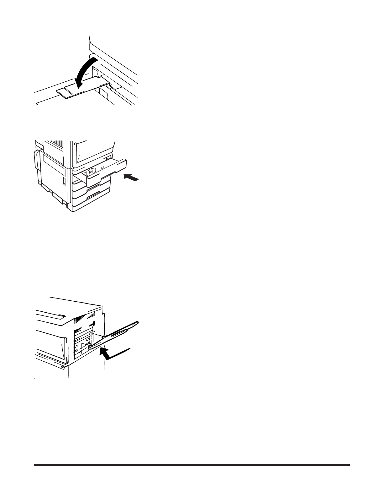
USA only
Swing the lift-up plate release lever back into position to lift up the
paper lift plate.
7. Push the universal cassette back into position.
Installing the paper exit tray
To attach the paper exit tray, insert the two hooks of the paper exit
tray into the lower holes of the paper exit section.
2-4 November 1996 A-62032
Page 11
Clearing paper jams
When a paper jam occurs, remove the paper jammed in each
section according to the following procedures.
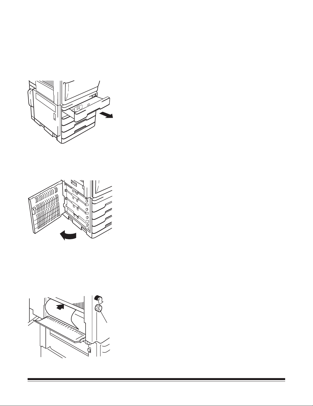
Inside the paper supply cabinet (J1 error)
1. Pull the paper cassettes out from the printer and check if the
paper in each cassette is stored correctly. If the paper is not
stored correctly, remove the jammed piece of paper. Push the
paper cassettes back into position.
2. Open the paper supply cabinet door (C2) and remove any
paper. Close the paper supply cabinet door.
3. If the leading edge of jammed paper has been fed into the
printer, open the front cover, send the paper into the printer
by rotating the transport roller knob (M5), and remove the
paper. (Refer to the “Jam Removal Diagram” label inside the
M5
A-62032 November 1996 2-5
printer front cover.) Close the front cover.
Page 12

Inside the printer (J2 or J3 error)
M2
1. Open the front cover and release lever M2 to unlock the
vacuum unit.
M5
M4
2. Open the transport section release plate (M4). Remove the
paper by rotating the transport roller knob (M5) or the
synchronizing roller knob (M3) in the direction of the arrow.
M3
3. When the leading edge of jammed paper has reached into the
fusing unit, remove the paper toward the inside of the printer
while depressing and rotating the roller knob (M1) in the
direction of the arrow.
NOTE: Rotate the roller knob (M1) only in the direction of the
arrow and do not remove the paper by pulling it into the
paper exit direction.
M1
2-6 November 1996 A-62032
Page 13

Inside the sorter and sorter interface unit (J4 or J6 error)
Lock Release Lever
1. Press the lock release lever of the 20-bin sorter to open the
sorter.
“Removing Jammed
Paper” diagram
2. Open the transport guide plates (upper and lower) of the
sorter to check if the paper is jammed inside the option. If the
paper has jammed, remove the paper. Close the transport
guide plates. (Refer to “Removing Jammed Paper” diagram
label as shown in illustration.)
NOTE: Open the lower transport guide plate for the 20-bin
sorter to check if the paper jammed inside. (Refer to
“Removing Jammed Paper” diagram label as shown in
illustration.)
A-62032 November 1996 2-7
Page 14

3. Open the upper cover of the sorter interface unit and check to
be sure there is no jammed paper. If there is paper, remove it
and close the upper cover again.
4. Close the 20-bin sorter.
2-8 November 1996 A-62032
Page 15

Changing a toner bottle
A toner bottle will print approximately 6,000 pages of A4 size
paper when the black-to-white ratio on the prints is 12%. When
the cartridge is out of toner, the toner empty indicator will light on
the operation panel. Replace the toner bottle by following the steps
below.
NOTE: Do not replace the toner bottle except when the toner
empty indicator appears.
1. Open the front cover.
1
2
Toner Bottle
Holder Lever
2. Pull the toner bottle holder lever to swing the toner bottle out
of the printer (1). Remove the toner bottle from the toner
holder (2).
3. Turning the toner seal right side up, insert the new toner
bottle into the holder so that the protrusions of the bottle fit in
the cutouts of the holder.
NOTE: Do not peel off the toner seal yet.
A-62032 November 1996 2-9
Page 16

4. Check that the triangle marks on the toner bottle and the toner
bottle holder face each other as in the illustration. Holding
the toner bottle with your left hand, gently pull the toner seal
out of the toner bottle.
5. Swing the toner bottle holder back into position.
6. Close the front cover.
2-10 November 1996 A-62032
Page 17

Changing the toner collection bottle
The used toner full indicator will appear on the operation panel
approximately every 100,000 prints when the black-to-white ratio
on the prints is 12%. When this indicator appears, follow the steps
below to replace the toner collection bottle.
1. Take out the toner collection bottle and cover the mouth with
the cap attached on the bottle.
2. Insert the new toner collection bottle into the printer.
A-62032 November 1996 2-11
Page 18

Appendix A Specifications
General specifications
Type.....................Console-type dry electrophotographic printer
Resolution ............ 400 DPI
Print method ........Laser diode, polygon mirror system
-3
Laser ....................Maximum power: 1.1 x 10
(W)
Wavelength: 785 +10, -15 nm
Dimensions .......... Width : 36" (860 mm) x depth : 27" (684 mm) x
height : 40" (1,006 mm)
Weight ................. 253 lb (115 kg)
Print speed ...........– First print
A4Y: 8 seconds or less
A3T: 8.3 seconds or less
– Multi print of same image
A4Y: 30 prints per minute
A3T: 18 prints per minute
Warmup time .......Within 3 minutes
Power supply .......120 V 60 Hz, 100 V 50/60 Hz,
220-240 V 50 Hz
Power
consumption (W)
Area Mode Printer
100/120 V warmup
standby
printing
220-240V warmup
standby
printing
alone
1220
270
1040
1440
270
1040
with
options
1240
290
1080
1460
290
1080
Acoustic noise......Printer alone
53 dB (A) or less (operation)
40 dB (A) or less (idle)
With options
58 dB (A) or less (operation)
40 dB (A) or less (idle)
Environment.........Temperature: 10–35°C (50–95°F)
Humidity: 15–85% RH
NOTE: Best performance will be obtained within the temperature
range of 15–25°C at a humidity range of 15–70% RH. Some
reduction of performance can be expected around 30°C
with RH above 70%.
Monthly prints......75,000 prints on average (150,000 prints
maximum)
Machine life ......... 4,800,000 prints or 5 years (whichever
occurs first)
A-62032 November 1996 A-1
Page 19

Option .................20-Bin Sorter with Sorter Interface Unit
Top Bin of sorter: 100-sheet capacity
Bins 2–20: 50-sheet capacity each
Paper feeding ....... Four Universal Cassettes each holding 350 sheets
Paper types .......... Standard paper: 60-90g/m
2
(16–24 lb)
Paper sizes
Paper Cassette
Size A B
A3 297 mm
(11.7 in.)
A4* 210 mm
(8.27 in.)
A5 148 mm
(5.83 in.)
JIS B4 257 mm
(10.12 in.)
JIS B5*
†
182 mm
(7.17 in.)
†
B6
129 mm
(5.08 in.)
Ledger 11.0 in.
(279.4 mm)
Legal 8.5 in.
(215.9 mm)
Letter* 8.5 in.
(215.9 mm)
420 mm
(16.5 in.)
297 mm
(11.7 in.)
210 mm
(8.27 in.)
364 mm
(14.3 in.)
257 mm
(10.12 in.)
182 mm
(7.17 in.)
17.0 in.
(431.8 mm)
14.0 in.
(355.6 mm)
11.0 in.
(279.4 mm)
Invoice 5.5 in.
(139.7 mm)
Executive* 7.25 in.
(184.2 mm)
7.0 x 8.5 in. 7.0 in.
(177.8 mm)
*These papers can be fed in either direction (i.e.,
dimensions are interchangeable for these sizes).
†
Feeds from upper 3 cassettes only.
A
NOTE:
• Dimension A cannot be greater than 11.7 in.
(297 mm).
B
Feed
Direction
• Dimension B
greater.
Smaller sizes may cause paper jams.
must
Paper output ........ Face up output system
8.5 in.
(215.9 mm)
10.5 in.
(266.7 mm)
8.5 in.
(215.9 mm)
be 8.25 in. (209.6 mm)
or
A-2 November 1996 A-62032
Page 20

Appendix B Installation considerations
Space requirements
The figures and illustrations below show the minimum space
required for the installation of your printer.
— Installed without sorter option
100 (4) 860 (34) 100 (4)
Unit: mm (inch)
1006 (39 5/8)
Top
684 (27) 100 (4)
A-62032 November 1996 B-1
Page 21

Installed with sorter option
Unit: mm (inch)
100 (4)
540 (21 1/4)
1093 (43)
100 (4)
553 (21 3/4)
1006 (39 5/8)
500 (19 3/4)
684 (27)
B-2 November 1996 A-62032
Page 22

Installation environment
Select the proper environment for using the printer to obtain the
optimum service from your printer. It should NOT be placed in a
location:
— which is exposed to direct sunlight.
— which is in the direct air stream of a cooler, heater, or
ventilator.
— where the temperature and the humidity are extremely high or
low. The room temperature should be 10–35°C (50–95°F) and
humidity should be 15–85% RH.
— which does not have a stable, level floor.
— which could easily get wet.
— which has poor ventilation and where ammonia gas might be
generated.
— which is far from a power supply.
NOTE: Please contact your service representative when you need to
move the printer to another place.
Power source
Before connecting the power cord of the printer to the outlet, check
the following items:
— Only connect to a dedicated electrical socket-outlet.
— Use the printer in a place which is near an electrical outlet
and where there is little voltage fluctuation. (The power
supply voltage should be specified voltage ±10% for imaging
and +10% or -15% for feeding. The power supply frequency
should be specified ±1 Hz.)
— Do not plug the power cord into a multi-socket extension
cord.
— At frequent intervals, check to see that the power plug is not
abnormally hot, that there are not any cracks or scrapes on
the cord, and that the power plug is fully inserted into the
socket.
— Be sure to use an outlet made for a 3-pin plug.
A-62032 November 1996 B-3
Page 23

Ordering information for the Printer 7 and accessories
CAT
No.
Kodak Imagelink
Kodak Imagelink
Kodak Imagelink
Kodak Imagelink
100 V, 50/60 Hz 128 5733
Kodak Imagelink
Kodak Imagelink
220-240 V, 50 Hz 859 1943
Kodak Imagelink
Kodak Imagelink
Kodak Imagelink
for Extension, Multiplexor or Printer 7 170 5268
Kodak Imagelink
for Extension, Multiplexor or Printer 7 143 3929
Kodak Imagelink
Printer 7 / 100 V, 50/60 Hz 104 8131
Printer 7 / 120 V, 60 Hz 159 9646
Printer 7 / 220-240 V, 50 Hz 887 9405
Printer 7 Paper Supply /
Printer 7 Paper Supply / 120 V, 60 Hz 852 6428
Printer 7 Paper Supply /
Printer 7 Sorter 864 6754
Printer 7 Sorter Interface 199 7964
Printer Cable, 10-foot /
Printer Cable, 20-foot /
Printer 5/7 Interface Board 173 0316
Ordering information for consumables for the Printer 7
Handling of consumables
CAT No.
Kodak Imagelink
Kodak Imagelink
Consumables such as paper and toner could affect the printer
condition. Before using any consumable, please carefully read the
label.
For paper and toner
— Do not keep paper and toner where they will be exposed to
direct sunlight, or in a place which is close to any kind of
heating device.
— To prevent absorption of moisture, paper which has been
removed from its wrapper but not loaded in the cassette
should be stored in a sealed plastic bag in a cool, dark place.
Printer 7 Toner 877 2220
Printer 7 Toner Collection Bottle 899 6670
— Never use the toner used for any other model of printer.
B-4 November 1996 A-62032
Page 24

Appendix C Printer 7 error, maintenance, and
caution codes
Error Codes
Code Explanation Action Needed
A0 No used toner collecting bottle. Seat the toner bottle properly; install one if
necessary.
A1 No EP unit. Seat the EP unit properly; install a new one if
necessary*; or call service. See page 1-3.
A2 No fuser. Seat the fuser correctly; install a new one if
necessary*; or call service. See page 1-3.
A3 Unacceptable paper at the sorter interface. Use paper specified for this printer. See page A-1.
E0 Unacceptable paper at the sorter. Use paper specified for this printer. See page A-1.
E1 The front cover is open. Close the front cover. See page 1-1.
E2 Cabinet door cover open Close the cabinet door. See page 1-1.
E3 The sorter bin cover is open. Close the sorter bin cover.
E4 The sorter interface cover is open. Close the sorter interface cover.
E5 The sorter bins are full of print paper. Empty all the sorter bins.
E6 Fuser web is empty. Install a new fuser unit* or call service.
E8 The sorter has been improperly installed in
the printer.
E9 Manual paper inserted. Remove the paper causing the jam.
J1 A paper jam has occurred between the
cassette and the synchronizing roller.
J2 A paper jam has occurred at the EP unit. Clear the jam. Open the front cover and clear the
J3 A paper jam has occurred between the
synchronizing roller and the fusing unit.
J4 A paper jam has occurred at the sorter. Clear the jam. Open sorter cover and clear the
J6 A paper jam has occurred at the sorter
interface.
20 The drum-charge erase lamp has
malfunctioned.
Correctly set the sorter to the printer.
Clear the jam. Open the front cover and cabinet
door and clear jam in stack. See page 2-5.
jam at the EP unit. See page 2-6.
Clear the jam. Open the front cover and clear the
jam. See page 2-6.
jam. See page 2-7.
Clear the jam. Open the sorter cover and sorter
interface cover and clear the jam. See page 2-7.
Turn the printer off and then on again. If the
problem persists, call for service.
* These maintenance procedures are to be performed by Kodak authorized and fully trained persons only. These
errors (for the EP unit and fuser unit) normally appear every 150,000 prints. At this time, an Image Quality Kit needs
to be installed. This kit includes: a new EP unit, a fuser unit, a transfer/separator corona, and feed rollers. Customers
with a Shared Maintenance Agreement will install the Image Quality Kit. Other customers should call Service
immediately.
A-62032 November 1996 C-1
Page 25

Error Codes (continued)
Code Explanation Action Needed
21 The drum-charge corona has malfunctioned. Turn the printer off and then on again. If the
problem persists, call for service.
22 The thermistor has malfunctioned. Turn the printer off and then on again. If the
problem persists, call for service.
23 An excessively high temperature has been
detected.
24 A heater lamp has malfunctioned. Turn the printer off and then on again. If the
25 The main drive motor has malfunctioned. Turn the printer off and then on again. If the
26 The transfer corona or separator has
malfunctioned.
27 The polygon drive motor has malfunctioned. Turn the printer off and then on again. If the
28 The S-SCAN-out has malfunctioned. Turn the printer off and then on again. If the
38 Command overflow. Call for service.
44 There is an error in the external
communications system.
46 The TSCR communications malfunctioned. Turn the printer off and then on again. If the
47 The sorter communications malfunctioned. Turn the printer off and then on again. If the
48 The sorter interface unit communications
malfunctioned.
Turn the printer off and then on again. If the
problem persists, call for service.
problem persists, call for service.
problem persists, call for service.
Turn the printer off and then on again. If the
problem persists, call for service.
problem persists, call for service.
problem persists, call for service.
Turn the printer off and then on again. If the
problem persists, call for service.
problem persists, call for service.
problem persists, call for service.
Turn the printer off and then on again. If the
problem persists, call for service.
49 Developing bias error. Turn the printer off and then on again. If the
problem persists, call for service.
50 PC drum drive malfunctioned Turn the printer off and then on again. If the
problem persists, call for service.
51 The develop roller drive malfunctioned. Turn the printer off and then on again. If the
problem persists, call for service.
52 The develop sleeve malfunctioned. Turn the printer off and then on again. If the
problem persists, call for service.
53 The toner supply motor malfunctioned. Turn the printer off and then on again. If the
problem persists, call for service.
54 Elevator tray 1 malfunctioned. Open paper cassette #1. Check paper position,
and close paper cassette. If the problem persists,
call for service.
C-2 November 1996 A-62032
Page 26

Error Codes (continued)
Code Explanation Action Needed
55 Elevator tray 2 malfunctioned. Open paper cassette #2. Check paper position,
and close paper cassette. If the problem persists,
call for service.
56 Elevator tray 3 malfunctioned. Open paper cassette #3. Check paper position,
and close paper cassette. If the problem persists,
call for service.
57 Elevator tray 4 malfunctioned. Open paper cassette #4. Check paper position,
and close paper cassette. If the problem persists,
call for service.
58 The ozone fan malfunctioned. Turn the printer off and then on again. If the
problem persists, call for service.
59 The power supply fan malfunctioned. Turn the printer off and then on again. If the
problem persists, call for service.
80 There is a problem with the sorter. Turn the printer off and then on again. If the
problem persists, call for service.
Preventive Maintenance Codes
Code Explanation Action Needed
P0 EP unit needs replacement. Install a new EP unit*, or call for service.
P2 The toner collection bottle is full. Replace with a new collection bottle. See
page 2-11.
Caution Codes
Code Explanation Action Needed
C0 The toner collection bottle is near full. The
printer will shut down approximately 500
Replace the toner collection bottle with a new
one. See page 2-11.
prints after this error is posted.
C1 The toner bottle is almost empty. Replace the toner bottle with a new one.
See page 2-9.
C2 The fuser web is almost used up. The printer
Replace with a new fuser unit* or call for service.
will shut down approximately 500 prints
after this error is posted.
* These maintenance procedures are to be performed by Kodak authorized and fully trained persons only.
These errors (for the EP unit and fuser unit) normally appear every 150,000 prints. At this time, an Image
Quality Kit needs to be installed. This kit includes: a new EP unit, a fuser unit, a transfer/separator corona,
and feed rollers. Customers with a Shared Maintenance Agreement will install the Image Quality Kit. Other
customers should call Service immediately.
A-62032 November 1996 C-3
Page 27

Appendix D Maintenance
Before conducting any maintenance procedures, follow these
precautions:
—Before beginning the maintenance procedures, be sure to turn
OFF the power ON/OFF switch and unplug the printer’s
power cord.
— Do not put any equipment that produces a magnetic field near
the printer.
— Do not attempt to remove the units other than those described
in the manual.
Use the mechanical print counter to check the number of prints
made to determine when certain maintenance procedures should
be performed.
Mechanical
Print Counter
Every 75,000 prints
Cleaning the image transfer/paper separator charger wires
The image transfer/paper separator charger wires should be cleaned
every 75,000 prints. Follow the steps described below to clean the
unit. Before cleaning the wire, be sure to turn OFF the power ON/
OFF switch and unplug the power cord.
1. Open the front cover. Release the lock of the vacuum unit
release lever (M2) and lower the vacuum unit. Push down on
the front edge of the image transfer/paper separator charger
and pull the charger out of the printer.
A-62032 November 1996 D-1
Page 28

2. Remove the (4) paper guides by lifting them straight up. Clean
the outside of housing with a soft cloth.
3. Carefully clean the wires using the cleaning pen contained in
the accessories for the machine as in the illustration.
4. Reinstall the four paper guides. Insert the image transfer/paper
separator charger onto the guides of the suction unit until the
charger is locked by the front edge of the guides. Lift up the
vacuum unit release lever (M2) and lock it into the EP unit.
Close the front cover.
NOTE: Be sure the charger is installed correctly. If the vacuum
unit will not lock into place or if there are printing
problems, reinstall the charger.
D-2 November 1996 A-62032
Page 29

Cleaning the printer
External cleaning
Internal cleaning
The printer should be cleaned on a regular basis to prevent
potential malfunctions. Before cleaning the printer, be sure to turn
off the power ON/OFF switch and unplug the power cord from the
outlet.
1. Wipe the cover and external parts of the printer with a dry,
soft cloth. If the cover is extremely dirty, use a cloth that has
been dampened slightly in a neutral cleaning solution.
1. Release the lock of the unit release lever (M2) and lower the
vacuum unit.
2. Wipe the belt of the vacuum unit with a dry and soft cloth.
A-62032 November 1996 D-3
Page 30

New equipment warranty—
Kodak Imagelink
Printer 7
Kodak warrants this equipment to function properly for three
months from date of shipment. However, certain requirements
may dictate a different warranty period. This warranty covers
the purchaser of this equipment as well as anyone else who
owns it during the warranty period.
Warranty repair coverage
Days and hours of coverage
How to obtain service
Limitations
If this equipment does not function properly during the
warranty period, Kodak will provide on-site repair service
during Kodak’s normal working hours. Such repair service will
include any adjustments and/or replacement of parts necessary
to maintain the equipment in an operating condition which is
consistent with Kodak’s specifications.
Warranty coverage is available Monday through Friday
during Kodak’s normal working hours (usually 8:00 a.m. to
5:00 p.m.), excluding holidays celebrated locally.
Any on-site service performed after normal working hours will
be billed at prevailing overtime rates.
In the U.S. call (800) 356-3253; or call your local Kodak
Service Office.
Standard warranty service is limited to the contiguous United
States, Hawaii, and certain areas of Alaska.
This warranty does not cover: circumstances beyond Kodak’s
control (such as Customer overriding, bypassing or defeating
interlock switches on equipment or devices sold by Kodak);
problems due to failure of Customer to conform to Kodak’s site
specifications; service or parts to correct problems resulting
from the use of attachments, accessories or alterations not
marketed by Kodak; relocation of equipment or service
required as the result of relocation; unauthorized modifications
or service; misuse; abuse; failure to follow Kodak’s operating
instructions; or supply items (such as glass and projection
lamps).
A-62032 November 1996
KODAK MAKES NO OTHER WARRANTIES, EXPRESS,
IMPLIED, OR OF MERCHANTABILITY OR FITNESS FOR A
PARTICULAR PURPOSE FOR THIS EQUIPMENT.
Repair or replacement without charge are Kodak’s only
obligations under this warranty. KODAK WILL NOT BE
RESPONSIBLE FOR ANY CONSEQUENTIAL OR INCIDENTAL
DAMAGES RESULTING FROM THE SALE, USE, OR
IMPROPER FUNCTIONING OF THIS EQUIPMENT,
REGARDLESS OF THE CAUSE. Such damages for which Kodak
will not be responsible, include, but are not limited to, loss of
revenue or profit, downtime costs, loss of use of the
equipment, cost of any substitute equipment, facilities or
services or claims of your customers for such damages.
Page 31

This limitation of liability will not apply to claims for injury to
persons or damage to property caused by the sole negligence
or fault of Kodak or by persons under its direction or control.
The
Kodak Imagelink
of 4.8 million print actuations or 5 years, whichever
occurs first. Kodak reserves the right to discontinue
service agreements or increase the service agreement
price when the life expectancy of the printer is reached.
Printer 7 has a rated machine life
A-62032 November 1996
Page 32

Index
A
Acoustic noise, A-1
Adjustable feet, 1-2
B
C
Cassettes (see also paper or
universal cassettes)
Caution codes, C-3
Circuit breaker, 1-2
Consumables
handling, B-4
ordering of, B-4
Mechanical print counter, 1-3,
D-1
“Metric” paper position switch,
2-2
N
O
Ordering information
accessories, B-4
consumables, B-4
Printer 7, B-4
Operation panel, 1-1, 2-1
Overview, 1-1–1-3
D
Dataplate, 1-2
E
Electrophotographic unit (see
EP unit)
Environment, A-1, B-3
EP unit, (See electrophoto-
graphic (EP unit), 1-3
Error codes, C-1–C-2
F
Feed roller, 1-3
Fusing roller knob (M1), 1-3
Fusing unit, 1-3
G
H
I
“Inch” paper position switch,
2-2
Installation
considerations, B-1
environment, B-2
Image transfer/paper separator
charger, 1-3
Image transfer/paper separator
ozone filter cover, 1-2
M
Machine life, A-1, Warranty
Maintenance, D-1–D-3
P
Paper,
clearing jams, 2-5–2-8
feeding, A-2
loading, 2-2
sizes, A-2
types, A-2
Paper cassette 1-1, 2-2–2-4
Paper exit tray, 1-2
installing, 2-4
Paper supply cabinet door, 1-1
Paper supply cabinet rear
cover, 1-2
Paper supply cabinet right
cover, 1-2
Paper take-up section release
knob, 1-3
Power
consumption, A-1
source, B-3
supplies, A-1
Power cord socket, 1-2
Power ON/OFF switch, 1-1,
2-1
Preventive maintenance codes,
C-3
Printer
installation
considerations, B-1
location/description of
parts, 1-1–1-3
overview, 1-1
print method, A-1
speed, A-1
A-62032 November 1996 Index-1
Page 33

status, 2-1
test print function, 2-1
turning on and off, 2-1
Printer cable interface socket,
1-2
Printer front cover, 1-1
Printer left cover, 1-1
Printer rear cover, 1-2
Printer right cover, 1-2
Printer top cover, 1-1
T
Test control, 2-1
Toner bottle, 1-3
changing, 2-9, 2-10
Toner bottle holder, 1-3
Toner collection bottle, 1-1
changing, 2-11
Transport roller knob (M5), 1-3
Transport section release plate
(M4), 1-3
Q
R
Release lever (M2), 1-3
S
Safety information, ii
Separator roller, 1-3
Sorter, 2-7, A-2, B-2
Sorter interface unit, 2-7, B-2
Space requirements, B-1, B-2
Specifications, A-1
Synchronizing roller knob
(M3), 1-3
U
Universal cassette (see paper
cassette)
V
Vertical transport roller knob
M6, 1-3
W
warnings, i, ii
warranty, IBC
Index-2 November 1996 A-62032
Page 34

A-62032 Part No. 3C4923 11/96©Eastman Kodak Company, 1996 Printed in U.S.A.
Business Imaging Systems
EASTMAN KODAK COMPANY
Rochester, New York 14650
Kodak and Imagelink are trademarks of
Eastman Kodak Company.
Printed on recycled paper.
 Loading...