

Page 1

Page 2

Contents
1 Introduction . . . . . . . . . . . . . . . . . . . . . . . . . . . . . . . . . . . . . . . . . . . . . . . . . 1
Scanner features . . . . . . . . . . . . . . . . . . . . . . . . . . . . . . . . . . . . . . . . . . . . . . 1
Safety information . . . . . . . . . . . . . . . . . . . . . . . . . . . . . . . . . . . . . . . . . . . . . 2
User precautions. . . . . . . . . . . . . . . . . . . . . . . . . . . . . . . . . . . . . . . . . . . . . 2
Environmental information . . . . . . . . . . . . . . . . . . . . . . . . . . . . . . . . . . . . . . 3
European Union . . . . . . . . . . . . . . . . . . . . . . . . . . . . . . . . . . . . . . . . . . . . . 3
EMC statements . . . . . . . . . . . . . . . . . . . . . . . . . . . . . . . . . . . . . . . . . . . . . . 3
United States . . . . . . . . . . . . . . . . . . . . . . . . . . . . . . . . . . . . . . . . . . . . . . . 3
Japan . . . . . . . . . . . . . . . . . . . . . . . . . . . . . . . . . . . . . . . . . . . . . . . . . . . . . 4
Korean . . . . . . . . . . . . . . . . . . . . . . . . . . . . . . . . . . . . . . . . . . . . . . . . . . . . 4
Acoustic emission . . . . . . . . . . . . . . . . . . . . . . . . . . . . . . . . . . . . . . . . . . . . . 4
Power system connection . . . . . . . . . . . . . . . . . . . . . . . . . . . . . . . . . . . . . . . 4
2 Getting Started . . . . . . . . . . . . . . . . . . . . . . . . . . . . . . . . . . . . . . . . . . . . . . 5
What’s in the box . . . . . . . . . . . . . . . . . . . . . . . . . . . . . . . . . . . . . . . . . . . . . 5
System requirements . . . . . . . . . . . . . . . . . . . . . . . . . . . . . . . . . . . . . . . . . . 5
Installing the scanner . . . . . . . . . . . . . . . . . . . . . . . . . . . . . . . . . . . . . . . . . . 5
Attaching the input and output trays . . . . . . . . . . . . . . . . . . . . . . . . . . . . . . . 6
Installing the Kodak Driver Software . . . . . . . . . . . . . . . . . . . . . . . . . . . . . . . 7
Connecting the power cord to the scanner . . . . . . . . . . . . . . . . . . . . . . . . . . 9
Disconnecting the power cord . . . . . . . . . . . . . . . . . . . . . . . . . . . . . . . . . . . . 9
Connecting the USB cable. . . . . . . . . . . . . . . . . . . . . . . . . . . . . . . . . . . . . . 10
Turning on the scanner and finalizing Kodak Driver Software installation . . 10
Installing application software . . . . . . . . . . . . . . . . . . . . . . . . . . . . . . . . . . . 12
Scanner components . . . . . . . . . . . . . . . . . . . . . . . . . . . . . . . . . . . . . . . . . . 12
Front view . . . . . . . . . . . . . . . . . . . . . . . . . . . . . . . . . . . . . . . . . . . . . . . . . 12
Inside view . . . . . . . . . . . . . . . . . . . . . . . . . . . . . . . . . . . . . . . . . . . . . . . . 13
Side views. . . . . . . . . . . . . . . . . . . . . . . . . . . . . . . . . . . . . . . . . . . . . . . . . 14
3 Using the Scanner . . . . . . . . . . . . . . . . . . . . . . . . . . . . . . . . . . . . . . . . . . 15
Turning the scanner on and off . . . . . . . . . . . . . . . . . . . . . . . . . . . . . . . . . . 15
Adjusting the input and output trays . . . . . . . . . . . . . . . . . . . . . . . . . . . . . . 15
Tray extenders and side guides . . . . . . . . . . . . . . . . . . . . . . . . . . . . . . . . 16
Adjusting the output tray . . . . . . . . . . . . . . . . . . . . . . . . . . . . . . . . . . . . . . 17
Start and stop scanning . . . . . . . . . . . . . . . . . . . . . . . . . . . . . . . . . . . . . . . . 18
Document preparation . . . . . . . . . . . . . . . . . . . . . . . . . . . . . . . . . . . . . . . . . 18
Verifying your scanner installation . . . . . . . . . . . . . . . . . . . . . . . . . . . . . . . . 19
Viewing test images . . . . . . . . . . . . . . . . . . . . . . . . . . . . . . . . . . . . . . . . . . . 21
Smart touch functionality . . . . . . . . . . . . . . . . . . . . . . . . . . . . . . . . . . . . . . . 22
Configuration dialog box . . . . . . . . . . . . . . . . . . . . . . . . . . . . . . . . . . . . . . 23
Scan To settings . . . . . . . . . . . . . . . . . . . . . . . . . . . . . . . . . . . . . . . . . . . . 24
Scan As settings . . . . . . . . . . . . . . . . . . . . . . . . . . . . . . . . . . . . . . . . . . . . 26
Configuring function numbers . . . . . . . . . . . . . . . . . . . . . . . . . . . . . . . . . . 27
Smart touch edit window. . . . . . . . . . . . . . . . . . . . . . . . . . . . . . . . . . . . . . 29
Using function numbers . . . . . . . . . . . . . . . . . . . . . . . . . . . . . . . . . . . . . . 30
Scanning your documents . . . . . . . . . . . . . . . . . . . . . . . . . . . . . . . . . . . . . . 31
Automatic feeding . . . . . . . . . . . . . . . . . . . . . . . . . . . . . . . . . . . . . . . . . . . . 31
Continuous feeding . . . . . . . . . . . . . . . . . . . . . . . . . . . . . . . . . . . . . . . . . . . 32
Manual feeding . . . . . . . . . . . . . . . . . . . . . . . . . . . . . . . . . . . . . . . . . . . . . . 32
Damaged documents. . . . . . . . . . . . . . . . . . . . . . . . . . . . . . . . . . . . . . . . . . 32
A-61550 May 2007 i
Page 3

4 Image Processing . . . . . . . . . . . . . . . . . . . . . . . . . . . . . . . . . . . . . . . . . . . 33
Overview . . . . . . . . . . . . . . . . . . . . . . . . . . . . . . . . . . . . . . . . . . . . . . . . . . . 33
Terminology and features. . . . . . . . . . . . . . . . . . . . . . . . . . . . . . . . . . . . . . . 33
Starting the Scan Validation Tool . . . . . . . . . . . . . . . . . . . . . . . . . . . . . . . . . 33
Scan Validation Tool dialog box . . . . . . . . . . . . . . . . . . . . . . . . . . . . . . . . . . 34
Using the TWAIN datasource. . . . . . . . . . . . . . . . . . . . . . . . . . . . . . . . . . . . 36
How do I begin? . . . . . . . . . . . . . . . . . . . . . . . . . . . . . . . . . . . . . . . . . . . . . . 36
Selecting Image settings. . . . . . . . . . . . . . . . . . . . . . . . . . . . . . . . . . . . . . 37
Selecting Device settings . . . . . . . . . . . . . . . . . . . . . . . . . . . . . . . . . . . . . 39
The main Kodak Scanner window . . . . . . . . . . . . . . . . . . . . . . . . . . . . . . . . 40
The Image Settings window. . . . . . . . . . . . . . . . . . . . . . . . . . . . . . . . . . . . . 43
Preview area . . . . . . . . . . . . . . . . . . . . . . . . . . . . . . . . . . . . . . . . . . . . . . . 44
General tab . . . . . . . . . . . . . . . . . . . . . . . . . . . . . . . . . . . . . . . . . . . . . . . . 45
Size tab . . . . . . . . . . . . . . . . . . . . . . . . . . . . . . . . . . . . . . . . . . . . . . . . . . . 47
Adjustments tab: black and white . . . . . . . . . . . . . . . . . . . . . . . . . . . . . . . 51
Adjustments tab: color or grayscale . . . . . . . . . . . . . . . . . . . . . . . . . . . . . 53
Enhancements tab . . . . . . . . . . . . . . . . . . . . . . . . . . . . . . . . . . . . . . . . . . 55
Defining custom dropout colors using the Color Dropout Configuration
window . . . . . . . . . . . . . . . . . . . . . . . . . . . . . . . . . . . . . . . . . . . . . . . . . . . 57
Color Dropout Configuration window - Single tab . . . . . . . . . . . . . . . . . . . . 59
Color Dropout Configuration window - Multiple tab . . . . . . . . . . . . . . . . . . . 62
Color Dropout Configuration window - Advanced tab . . . . . . . . . . . . . . . . . 65
Advanced Image Setup . . . . . . . . . . . . . . . . . . . . . . . . . . . . . . . . . . . . . . . . 67
The Advanced tab. . . . . . . . . . . . . . . . . . . . . . . . . . . . . . . . . . . . . . . . . . . 67
Content Settings tab . . . . . . . . . . . . . . . . . . . . . . . . . . . . . . . . . . . . . . . . . 70
Creating color/grayscale or black and white images based on the
contents of your documents, Example 1. . . . . . . . . . . . . . . . . . . . . . . . . . 72
Creating multiple images for each side of a document, Example 2. . . . . . . 74
Creating different settings for each side of a document, Example 3 . . . . . . 76
Creating a new shortcut . . . . . . . . . . . . . . . . . . . . . . . . . . . . . . . . . . . . . . . . 78
Changing Image settings . . . . . . . . . . . . . . . . . . . . . . . . . . . . . . . . . . . . . . . 80
Creating a custom dropout color to drop a single color . . . . . . . . . . . . . . . . 81
Creating a custom dropout color to drop multiple colors . . . . . . . . . . . . . . . 82
The Device Settings window . . . . . . . . . . . . . . . . . . . . . . . . . . . . . . . . . . . . 83
Device - General tab . . . . . . . . . . . . . . . . . . . . . . . . . . . . . . . . . . . . . . . . . 84
Device - Printer tab . . . . . . . . . . . . . . . . . . . . . . . . . . . . . . . . . . . . . . . . . . 86
Device - Multifeed tab . . . . . . . . . . . . . . . . . . . . . . . . . . . . . . . . . . . . . . . . 89
Changing Device settings . . . . . . . . . . . . . . . . . . . . . . . . . . . . . . . . . . . . . . 91
The Diagnostics window . . . . . . . . . . . . . . . . . . . . . . . . . . . . . . . . . . . . . . . 92
Diagnostics - General tab . . . . . . . . . . . . . . . . . . . . . . . . . . . . . . . . . . . . . 93
Diagnostics - Debug tab . . . . . . . . . . . . . . . . . . . . . . . . . . . . . . . . . . . . . . 95
Diagnostics - Logs tab . . . . . . . . . . . . . . . . . . . . . . . . . . . . . . . . . . . . . . . 97
ii A-61550 May 2007
Page 4

Using the ISIS Driver . . . . . . . . . . . . . . . . . . . . . . . . . . . . . . . . . . . . . . . . . . 98
The main ISIS Driver window. . . . . . . . . . . . . . . . . . . . . . . . . . . . . . . . . . . . 98
Main tab . . . . . . . . . . . . . . . . . . . . . . . . . . . . . . . . . . . . . . . . . . . . . . . . . . 99
Layout tab . . . . . . . . . . . . . . . . . . . . . . . . . . . . . . . . . . . . . . . . . . . . . . . . 102
Image Processing tab . . . . . . . . . . . . . . . . . . . . . . . . . . . . . . . . . . . . . . . 103
Scanner tab. . . . . . . . . . . . . . . . . . . . . . . . . . . . . . . . . . . . . . . . . . . . . . . 105
Auto Color Detect tab . . . . . . . . . . . . . . . . . . . . . . . . . . . . . . . . . . . . . . . 107
Adjustments tab . . . . . . . . . . . . . . . . . . . . . . . . . . . . . . . . . . . . . . . . . . . 109
Dropout tab . . . . . . . . . . . . . . . . . . . . . . . . . . . . . . . . . . . . . . . . . . . . . . . . 111
Logs tab . . . . . . . . . . . . . . . . . . . . . . . . . . . . . . . . . . . . . . . . . . . . . . . . . .112
About tab. . . . . . . . . . . . . . . . . . . . . . . . . . . . . . . . . . . . . . . . . . . . . . . . . .112
Scan Area dialog box . . . . . . . . . . . . . . . . . . . . . . . . . . . . . . . . . . . . . . . .113
5 Document Printing
Printer specifications . . . . . . . . . . . . . . . . . . . . . . . . . . . . . . . . . . . . . . . . . .116
Installing/Replacing the ink cartridge . . . . . . . . . . . . . . . . . . . . . . . . . . . . . .117
Enhanced Printer . . . . . . . . . . . . . . . . . . . . . . . . . . . . . . . . . . . . . . . . . . . . .118
Document Printer . . . . . . . . . . . . . . . . . . . . . . . . . . . . . . . . . . . . . . . . . . . . 120
Changing print positions . . . . . . . . . . . . . . . . . . . . . . . . . . . . . . . . . . . . . . 122
Changing the print position . . . . . . . . . . . . . . . . . . . . . . . . . . . . . . . . . . . . 122
Replacing the ink blotter strips. . . . . . . . . . . . . . . . . . . . . . . . . . . . . . . . . . 123
Supplies . . . . . . . . . . . . . . . . . . . . . . . . . . . . . . . . . . . . . . . . . . . . . . . . . . . 124
Problem solving . . . . . . . . . . . . . . . . . . . . . . . . . . . . . . . . . . . . . . . . . . . . . 125
6 Maintenance . . . . . . . . . . . . . . . . . . . . . . . . . . . . . . . . . . . . . . . . . . . . . . 126
Supplies and consumables . . . . . . . . . . . . . . . . . . . . . . . . . . . . . . . . . . . . 127
Cleaning the separator module . . . . . . . . . . . . . . . . . . . . . . . . . . . . . . . . . 128
Cleaning the feed module . . . . . . . . . . . . . . . . . . . . . . . . . . . . . . . . . . . . . 130
Cleaning the drive rollers and transport area . . . . . . . . . . . . . . . . . . . . . . 132
Cleaning the imaging guides . . . . . . . . . . . . . . . . . . . . . . . . . . . . . . . . . . . 133
Cleaning the paper path . . . . . . . . . . . . . . . . . . . . . . . . . . . . . . . . . . . . . . 134
Replacing parts . . . . . . . . . . . . . . . . . . . . . . . . . . . . . . . . . . . . . . . . . . . . . 134
Replacing the feed module and feed module tires. . . . . . . . . . . . . . . . . . . 135
Replacing the separator module and separator module tires . . . . . . . . . . 137
Replacing the pre-separation pad . . . . . . . . . . . . . . . . . . . . . . . . . . . . . . . 139
Replacing the imaging guides . . . . . . . . . . . . . . . . . . . . . . . . . . . . . . . . . . 140
7 Troubleshooting . . . . . . . . . . . . . . . . . . . . . . . . . . . . . . . . . . . . . . . . . . . 143
Indicator lights and error codes . . . . . . . . . . . . . . . . . . . . . . . . . . . . . . . . . 143
Service indicator lights . . . . . . . . . . . . . . . . . . . . . . . . . . . . . . . . . . . . . . . . 143
Lamps . . . . . . . . . . . . . . . . . . . . . . . . . . . . . . . . . . . . . . . . . . . . . . . . . . . . 143
Clearing document jams . . . . . . . . . . . . . . . . . . . . . . . . . . . . . . . . . . . . . . 144
Problem solving . . . . . . . . . . . . . . . . . . . . . . . . . . . . . . . . . . . . . . . . . . . . 145
Appendix A Specifications 147
Appendix B TWAIN Image Processing Terminology . . . . . . . . . . . . . . . . . 148
A-61550 May 2007 iii
Page 5

Appendix c Warranty - US and Canada only . . . . . . . . . . . . . . . . . . . . . . . 150
Limited warranty for Kodak Scanners . . . . . . . . . . . . . . . . . . . . . . . . . . . . 150
Warranty exclusions. . . . . . . . . . . . . . . . . . . . . . . . . . . . . . . . . . . . . . . . . . 151
Installation Warning and Disclaimer. . . . . . . . . . . . . . . . . . . . . . . . . . . . . . 152
How to obtain limited warranty service . . . . . . . . . . . . . . . . . . . . . . . . . . . 152
Packaging and shipping guidelines . . . . . . . . . . . . . . . . . . . . . . . . . . . . . . 153
Return procedure . . . . . . . . . . . . . . . . . . . . . . . . . . . . . . . . . . . . . . . . . . . . 153
Customer responsibility . . . . . . . . . . . . . . . . . . . . . . . . . . . . . . . . . . . . . . . 153
Warranty Service description . . . . . . . . . . . . . . . . . . . . . . . . . . . . . . . . . . . 153
On-site service . . . . . . . . . . . . . . . . . . . . . . . . . . . . . . . . . . . . . . . . . . . . . . 154
AUR . . . . . . . . . . . . . . . . . . . . . . . . . . . . . . . . . . . . . . . . . . . . . . . . . . . . . . 154
Depot service . . . . . . . . . . . . . . . . . . . . . . . . . . . . . . . . . . . . . . . . . . . . . . . 155
Important restrictions . . . . . . . . . . . . . . . . . . . . . . . . . . . . . . . . . . . . . . . 156
Contacting Kodak. . . . . . . . . . . . . . . . . . . . . . . . . . . . . . . . . . . . . . . . . . . . 156
iv A-61550 May 2007
Page 6
1 Introduction
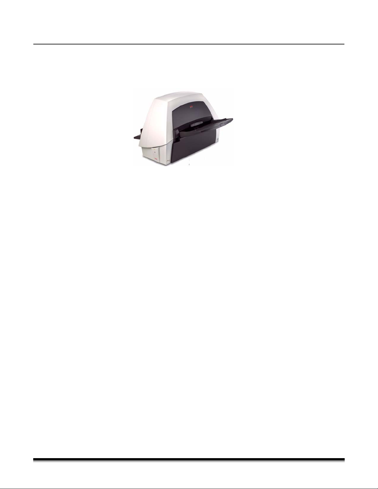
The Kodak i1400 Series Scanners include the following models:
Kodak i1410 Scanner — desktop
simplex color scanner that scans
up to 60 ppm (300 dpi, black and
white, landscape orientation) lettersize documents.
Kodak i1420 Scanner — desktop
duplex color scanner that scans up
to 60 ppm (300 dpi, black and
white, landscape orientation) lettersize documents.
Kodak i1440 Scanner — desktop duplex color scanner that scans up
to 75 ppm (300 dpi, black and white, landscape orientation) letter-size
documents.
This User’s Guide provides information and procedures for using and
maintaining the Kodak i1400 Series Scanners. The information in this
guide is for use with all scanner models unless otherwise noted.
Scanner features • Easy to use
• Small, compact size
• Scans up to
document feeder
• Simultaneous black and white and color/grayscale image output
• Document printing capabilities for the Kodak i1420 and i1440
Scanners
• Smart touch functionality allows you to send documents to file, email,
printers, fax printers or desktop applications that support TIFF, JPEG,
RTF, PDF and searchable PDF
• Easily replaceable feed and separator modules
• Output resolutions from 75 to 1200 dpi
• Image processing features include Kodak’s Perfect Page technology
for black and white, grayscale and color images
• Bundled ISIS and TWAIN drivers
• High speed USB 2.0 interface
• Optional A3 flatbed easily connects and disconnects to the scanner
30.5 x 86 cm / 12 x 34 inches using the automatic
A-61550 May 2007 1
Page 7
Safety information • When placing the scanner, make sure that the electrical power outlet
is located within 1.52 meters (5 feet) of the scanner and is easily
accessible.
• Use only the power supply that was provided with the Kodak i1400
Series Scanner. Do not substitute another power supply model or
another manufacturer’s power supply.
• This product is designed for connection to IT power systems.
• The printer access door must be in place and closed during scanner
operation, except when changing the print head location or replacing
the ink cartridge. When the printer access door is removed, do not
allow loose clothing, jewelry, hair or other objects to enter the printer
opening.
• Material Safety Data Sheets (MSDS) for chemical products are
available on the Kodak website at: www.kodak.com/go/msds. When
accessing the MSDSs from the website, you will be required to
provide the catalog number of the consumable you want the Material
Safety Data Sheet for. See the section entitled, “Supplies and
consumables” later in this guide for supplies and catalog numbers.
Warning labels
CAUTION: Moving parts, avoid contact.
CAUTION: Hot surface, avoid contact.
User precautions Users and their employer need to observe the common sense
precautions applicable to the operation of any machinery. These
include, but are not limited to, the following:
• Do not wear loose clothing, unbuttoned sleeves, etc.
• Do not wear loose jewelry, bracelets, bulky rings, long necklaces, etc.
• Hair length should be kept short, using a hair net if needed, or tying
long hair up in a bundle.
• Remove all other loose objects from the area that could be drawn into
the machine.
• Take sufficient breaks to maintain mental alertness.
• Use only the recommended cleaning supplies.
• Do not use canned/compressed air.
Supervisors should review their practices and make compliance with
these precautions a part of the job description for operation of the
scanner or any mechanical device.
2 A-61550 May 2007
Page 8

Environmental information
• The Kodak i1400 Series Scanners are designed to meet worldwide
environmental requirements.
• Guidelines are available for the disposal of consumable items that
are replaced during maintenance or service; follow local regulations
or contact Kodak locally for more information.
• The product packaging is recyclable.
• The Kodak i1400 Series Scanners are Energy Star compliant and are
shipped from the factory with the default time set to 15 minutes.
European Union This symbol indicates that when the last user wishes to discard this
product, it must be sent to appropriate facilities for recovery and
recycling. Please contact your local Kodak representative or refer to
www.kodak.com/go/recycle for additional information on the collection
and recovery programs available for this product.
EMC statements
United States This equipment has been tested and found to comply with the limits for
a Class B digital device pursuant to Part 15 of the FCC rules. These
limits are designed to provide reasonable protection against harmful
interference in a residential installation. This equipment generates,
uses, and can radiate radio frequency energy and, if not installed and
used in accordance with the instruction manual, may cause harmful
interference to radio communications. However, there is no guarantee
that interference will not occur in a particular installation. If this
equipment does cause harmful interference to radio or television
reception, which can be determined by turning the equipment off and
on, the user is encouraged to try to correct the interference by one or
more of the following measures:
- Reorient or relocate the receiving antenna.
- Increase the separation between the equipment and receiver.
- Connect the equipment into an outlet on a circuit different from
that to which the receiver is connected.
- Consult the dealer or an experienced radio/TV technician for
additional suggestions.
Any changes or modifications not expressly approved by the party
responsible for compliance could void the user’s authority to operate
the equipment. Where shielded interface cables have been provided
with the product or specified additional components or accessories
elsewhere defined to be used with the installation of the product, they
must be used in order to ensure compliance with FCC regulation.
A-61550 May 2007 3
Page 9

Japan This is a Class B product based on the standard of the Voluntary
Control Council for interference by information Technology Equipment
(VCCI). If this is used near a radio or television receiver in a domestic
environment, it may cause radio interference. Install and use the
equipment according to the instruction manual.
Korean As this equipment has obtained EMC registration for household use, it
can be used in any area including residential areas.
Acoustic emission Maschinenlärminformationsverordnung – 3, GSGV
Der arbeitsplatzbezogene Emissionswert beträgt <70 db(A).
Power system connection
[Machine Noise Information Ordinance — 3, GSGV
The operator-position noise emission value is <70 dB(A).]
This product is also designed for Norwegian IT power system with
phase-to-phase voltage 230V.
Netzanschluß
Das Gerät ist auch für die Verwendung im norwegischen ITStromsystem mit einer Leiterspannung von 230 V geeignet.
Connexion aux systèmes d’alimentation électrique
Ce produit est également conçu pour les systèmes norvégiens
d’alimentation électrique informatique, dont la tension par phase est de
230 V.
4 A-61550 May 2007
Page 10

2 Getting Started
What’s in the box Before you begin open the box and check the contents:
• Kodak i1410, i1420 or i1440 Scanner
• Input tray
• Output tray
• USB 2.0 cable
• Power supply
• AC power cord bundles
• Welcome Folio which includes:
- Bundled installation and application CDs
- Registration sheets
- Printed User’s Guide, English
- Service Contact sheets
- Quick Installation Guide
-Quick Tips Guide
- Miscellaneous flyers
System requirements Following is the recommended system configuration to run Kodak i1400
Series Scanners.
• Intel Pentium IV, 3.5 GHz processor
• USB port 2.0
• Windows 2000, Service Pack 4 and Windows XP (Professional/
Home), Service Pack 2; Windows Vista
• 200 MB free hard disk space
• 3 GB of RAM
Installing the scanner Install the scanner in the following order:
1. Attach the input and output trays.
2. Install the Kodak Driver Software.
3. Connect the power cord to the scanner.
4. Connect the USB cable between your scanner and PC.
5. Turn on scanner power and finalize the Kodak Driver Software
installation.
6. Install other supplied applications (optional).
IMPORTANT:Install the Kodak Driver Software on the host PC
before you connect the scanner.
A-61550 May 2007 5
Page 11

Attaching the input and output trays
The input and output trays snap into place. The input and output trays
can also be adjusted to fit different document sizes.
Attaching the input tray
1. Locate the input tray slots on the scanner.
2. Align the input tray pins with the slots.
3. Snap the input tray into place.
Attaching the output tray
1. Locate the output tray slots on the scanner.
2. Align the output tray pins with the slots.
3. Snap the output tray into place.
6 A-61550 May 2007
Page 12
Installing the Kodak Driver Software
Install the driver software before connecting the scanner to your PC.
1. Insert the Kodak i1400 Series Scanner Installation CD in the CD-
ROM drive. The installation program starts automatically.
NOTE: If the CD does not start automatically, open the My
Computer icon on your desktop. Double-click the icon for
your CD-ROM drive, then double-click on Install Scanner
Software.
2. Select Install Scanner Software. The following message may be
displayed, Portions of this application are already installed.
Existing files will be upgraded as necessary. Continue with
installation? If the message is displayed, click Yes.
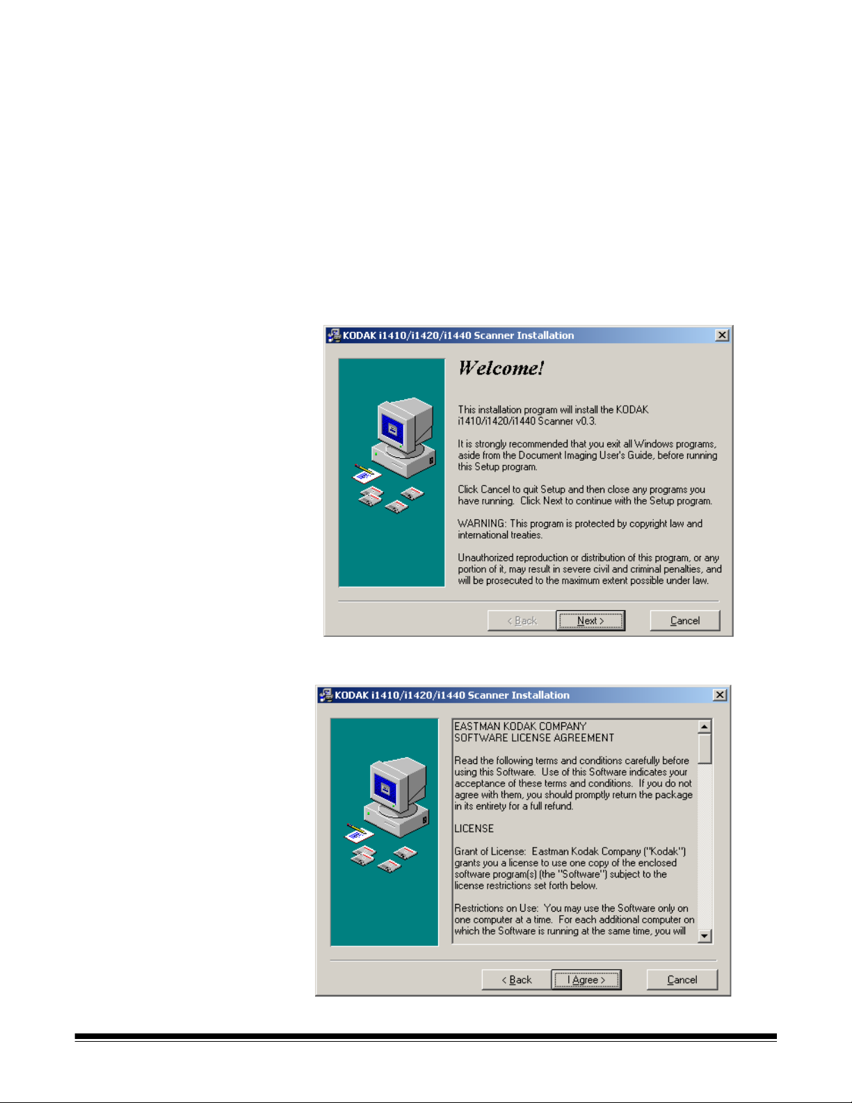
The Welcome window will be displayed.
3. Click Next. The Software License Agreement window will be
displayed.
4. After reading the agreement, click I Agree to continue.
A-61550 May 2007 7
Page 13
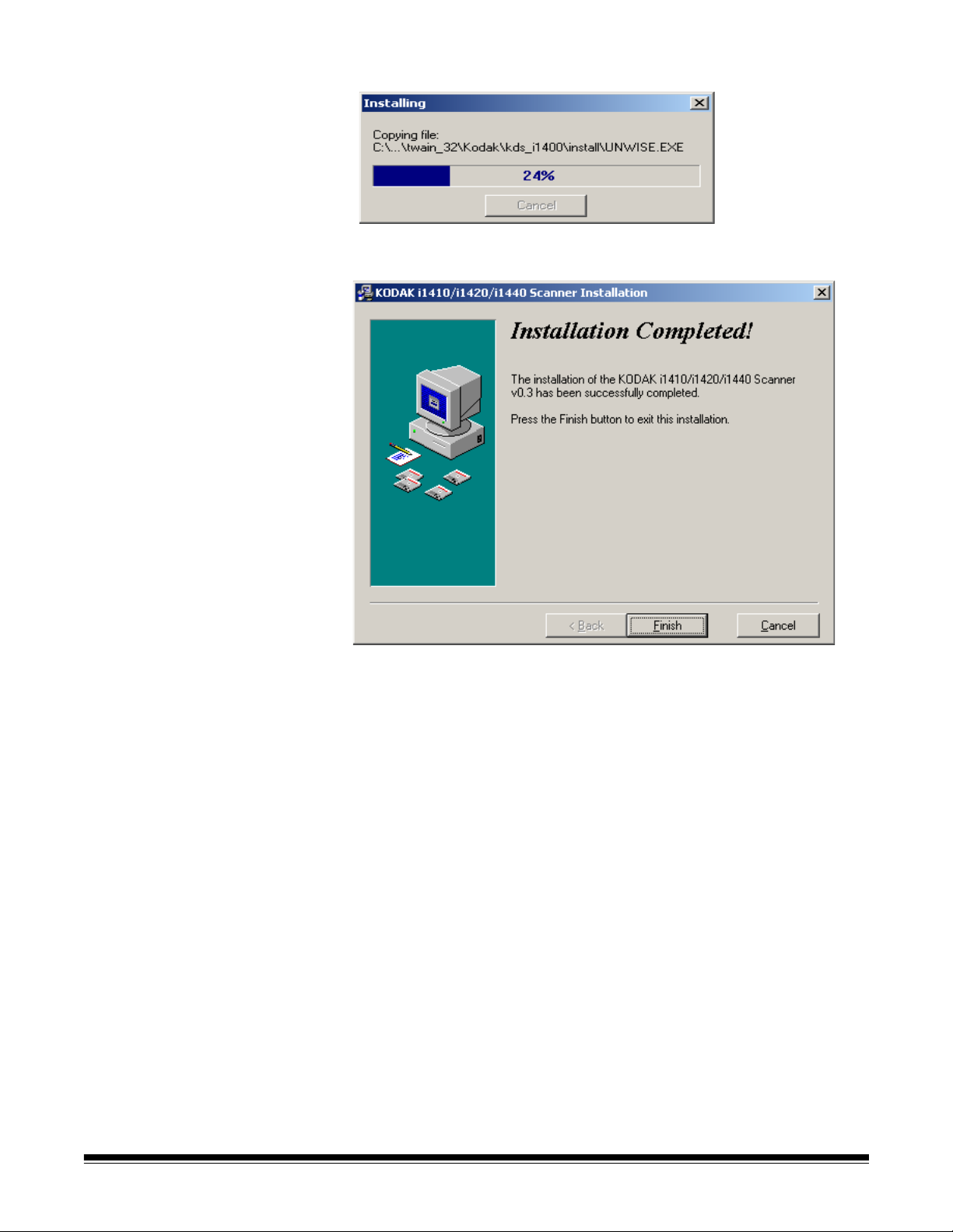
The installation will start.
5. When the installation is complete, the Installation Completed
window will be displayed.
6. Click Finish.
8 A-61550 May 2007
Page 14

Connecting the power cord to the scanner
Use only the power supply that was provided with the Kodak i1400
Series Scanner. Do not substitute another power supply model or
another manufacturer’s power supply.
When the drivers have been installed, connect the power supply and
power cord to the scanner. Make sure that the power outlet is located
within 1.52 metres (5 feet) of the scanner and is easily accessible.
1. Select the appropriate AC power cord for your region from the
supply of power cords packed with your scanner.
2. Attach the power cord for your power type to the power supply.
3. Plug the output power cord from the power supply into the power
port on the scanner.
4. Plug the other end of the power cord into the wall outlet.
Disconnecting the power
cord
A-61550 May 2007 9
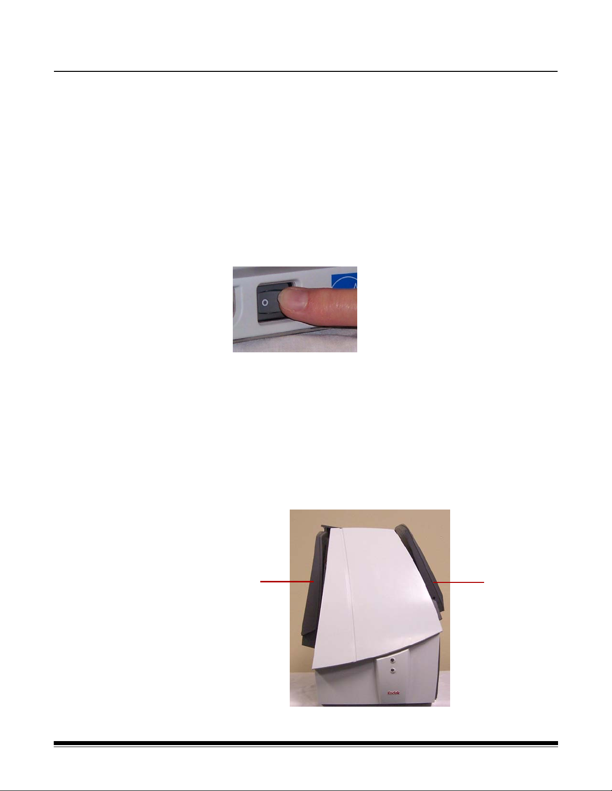
To disconnect the power cord from the scanner:
• Place your thumb on the arrow on the collar of the power connector
and pull it away from the scanner.
Page 15
Connecting the USB cable
IMPORTANT: If you have not installed the Kodak Driver Software,
do that now before proceeding.
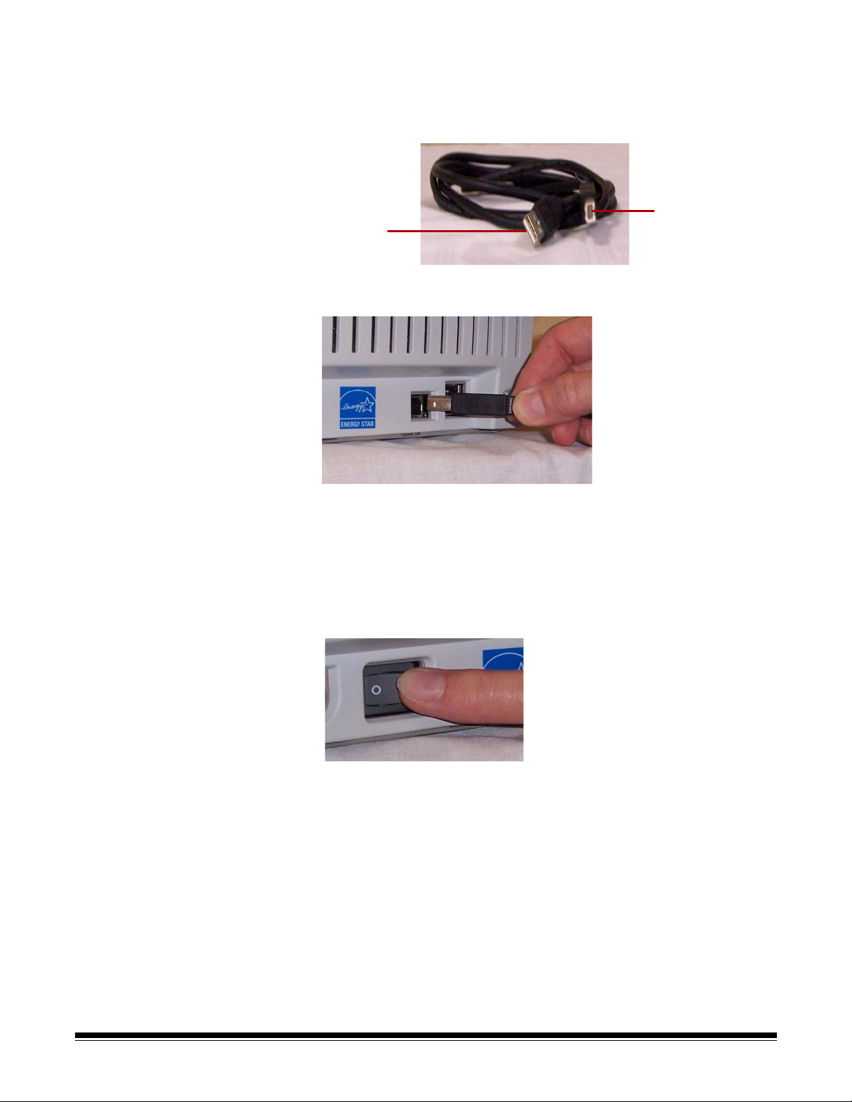
The USB cable supplied with your scanner has two different ends.
B
A
1. Attach the B end of the USB cable to the scanner USB port, located
on the back of the scanner.
Turning on the scanner and finalizing Kodak Driver Software installation
2. Attach the A end of the USB cable to the proper USB port on your
PC.
When the USB cable and power connections have been made, and the
Kodak Software Drivers have been properly installed, the installation
will be completed when the scanner is turned on.
1. Turn on the power to the scanner.
When you turn on the scanner, the scanner goes through a series of
self tests, the indicators will flash. When it is finished and ready to
scan, the LED indicator will stop flashing and stay green.
NOTES:
• The following screens are based on Windows XP. Depending on
the computer operating system you are using, these screens
may be slightly different.
• If a flatbed is attached, the New Hardware screen may be
displayed once for the scanner and once for the flatbed.
10 A-61550 May 2007
Page 16
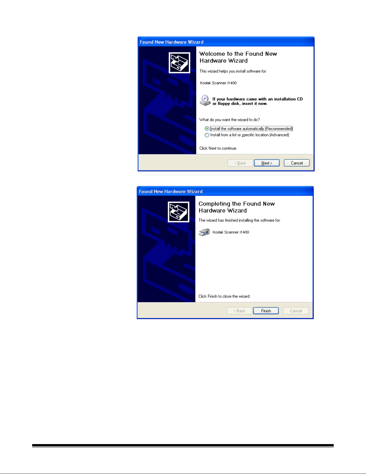
Your operating software will now auto detect the scanner.
2. Click Next. The following screen will be displayed.
3. Click Finish.
The installation of the Kodak Driver Software for the scanner is
complete. To test the scanner, refer to the section entitled, “Verifying
your scanner installation” in Chapter 3.
A-61550 May 2007 11
Page 17
Installing application software
Scanner components
Front view
The following Kodak applications are available on the CDs packed with
your scanner.
• Kodak Capture Software Lite
• Kodak Scan Validation Tool
Other scanning applications may also be provided on the CDs packed
with your scanner. Review these CDs for any other applications that are
included. You may also use third-party scanning applications not
provided. See the User Guides provided with these applications for
instructions on how to install and use the software.
1
7
2
3
4
5
6
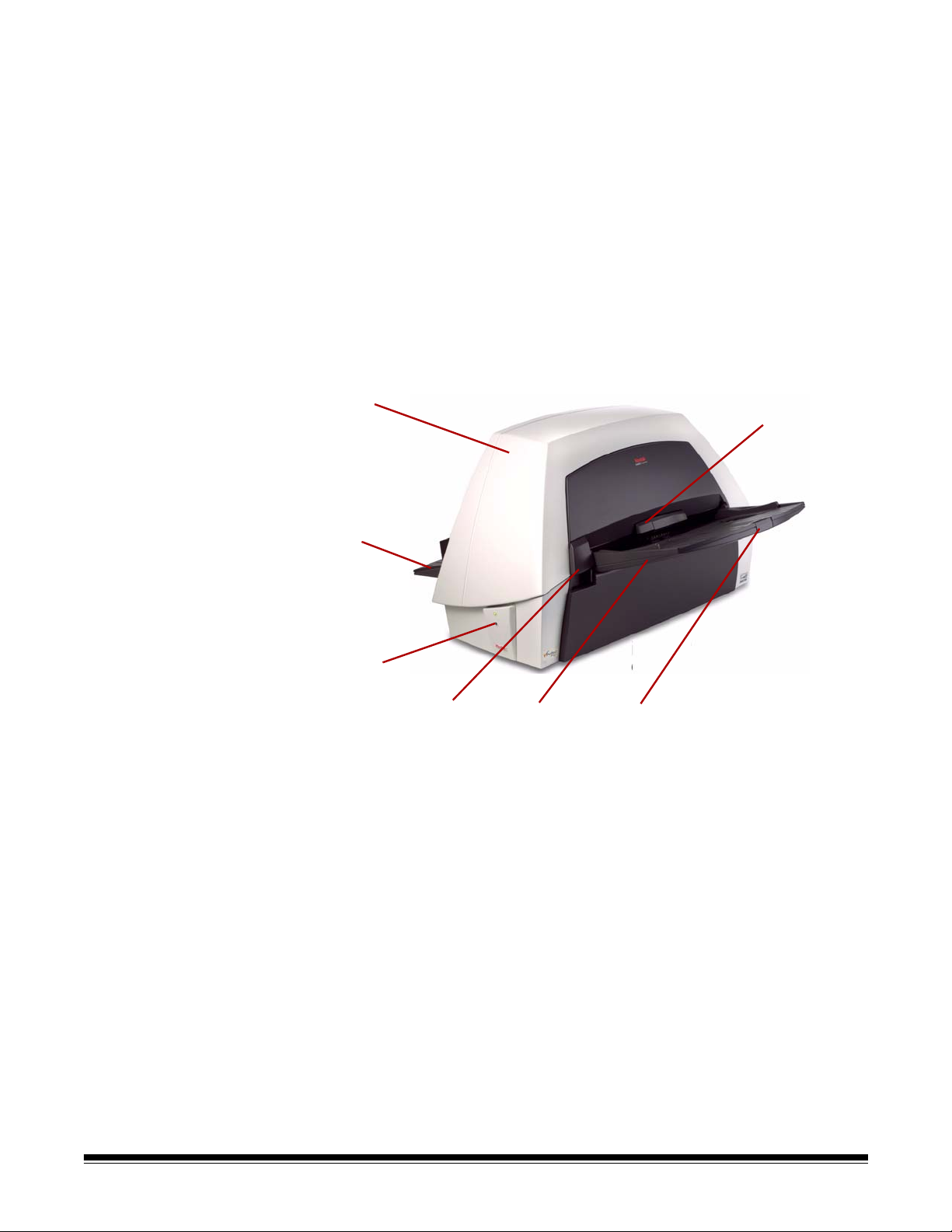
1 Scanner cover — provides access to the internal components of
the scanner.
2 Output tray — collects the scanned documents.
3LEDs — illuminates or flashes indicating scanner status.
4 Scanner cover release lever — push up on this lever to open the
scanner cover.
5 Input tray — holds up to 100 documents (20 lb./75 g/m
2
) in place.
6 Input tray extender — pull this extender out when scanning
documents longer than 21.6 x 27.9 cm (8.5 x 11 inches).
7 Gap release lever — push up on this lever to adjust the space
between the feed module and separator module for documents
that require special handling.
12 A-61550 May 2007
Page 18

Inside view
1
2
3
4
6
5
1 Separator module — provides smooth document feeding and
separation of various sizes, thicknesses and textures of
documents.
2Rollers — provides smooth transport of documents through the
scanner.
3 Rear roller cover — provides access to the rear rollers for
cleaning.
4 Front roller cover — provides access to the feed module. This
cover needs to be removed when cleaning or replacing the feed
module or feed module tires.
5 Feed module — provides smooth document feeding and
separation of various sizes, thicknesses and textures of
documents.
6 Imaging guides — keep imaging guides clean to obtain optimum
image quality.
NOTE:The Kodak i1410 Scanner does not have an upper imaging
guide.
A-61550 May 2007 13
Page 19
Side views
3
1
4
2
5
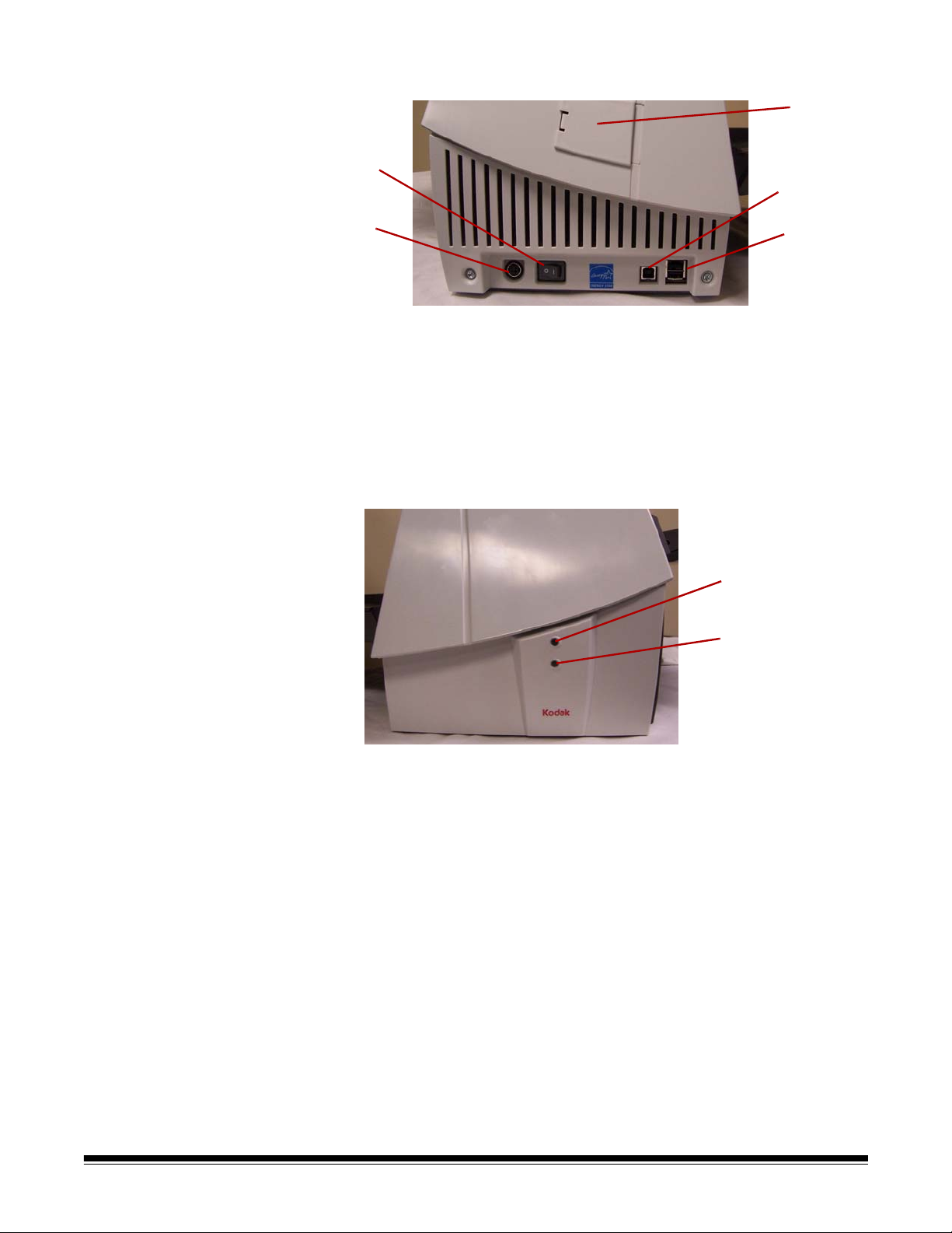
1 Power button — turns the power to the scanner on (|) and off (O).
2 Power port — connects the power cord to the scanner.
3 Side access door — provides access to the upper imaging guide
for replacement (Kodak i1420 and i1440 Scanners only).
4 USB port — connects the scanner to the PC.
5 Flatbed/USB port — connects the optional A3 Flatbed to the
scanner.
6
7
6 Top LED — flashing red when an error has been encountered.
7 Bottom LED — steady green when the scanner is ready to scan;
flashing green when the scanner is preparing to scan.
14 A-61550 May 2007
Page 20
3 Using the Scanner
This chapter provides procedures for:
• Turning the scanner power on and off
• Adjusting the input and output trays
• Preparing your documents for scanning
• Verifying your scanning installation
• Scanning documents: automatic feeding, manual feeding and
continuous feeding
Turning the scanner on and off
Adjusting the input and output trays
• Turn the power on to the scanner.
After you turn on the scanner, wait for it to complete the self-test. When
completed, the green indicator light will remain on and constant.
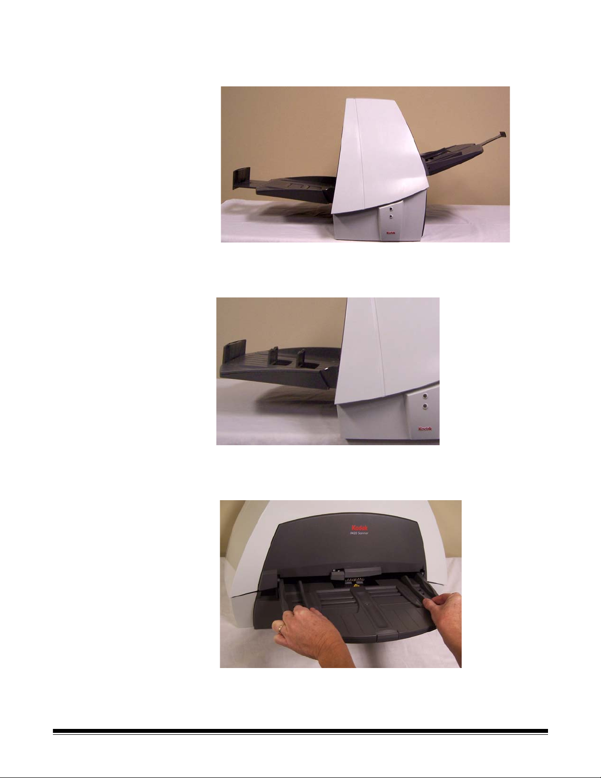
The input and output trays may be adjusted to fit different document
sizes. The input and output trays also may be folded flat up against the
scanner to save space when the scanner is not in use.
To fold the scanner trays:
• Grasp the input tray/output tray and lift it up until it rests against the
scanner front/back.
Output tray
A-61550 May 2007 15
Input tray
Page 21
Tray extenders and side guides
• Both the input and output trays have extenders to accommodate long
documents. Grasp the tray extender and pull it out to the desired
position.
• The output tray also has two document stops that can be raised to
accommodate the collection of small documents after they have been
scanned.
• The input tray has side guides that allow you to adjust the feeder to fit
different document sizes. Grasp the side guides and slide them in or
out to the desired position.
16 A-61550 May 2007
Page 22

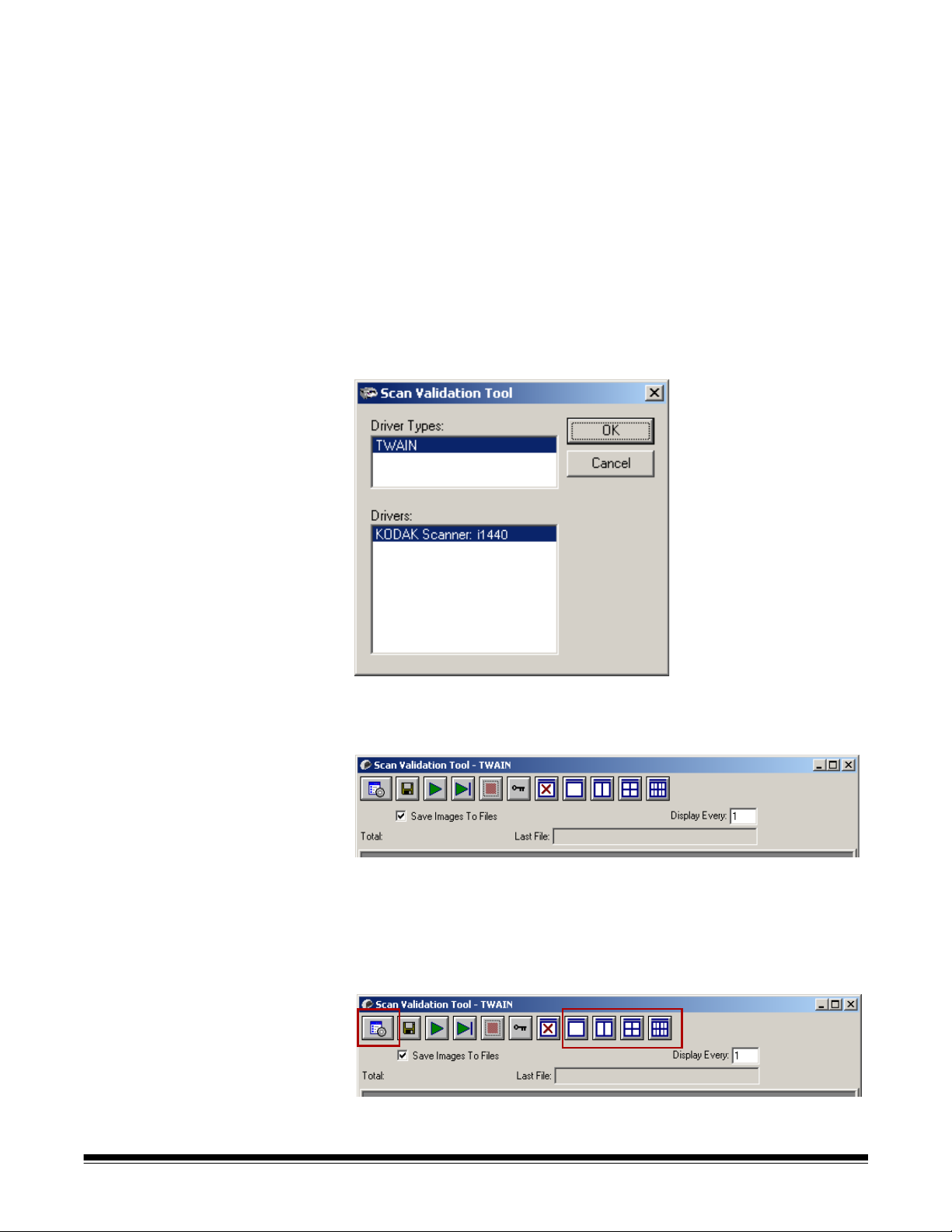
Adjusting the output tray The output tray has three possible positions.
Lowest position for
long documents
Middle position for
letter or A4 documents
Highest position
for checks and small
documents
• Set the output tray to the lowest position when you are scanning
long documents.
• Set the output tray to the middle position when you are scanning
letter- or A4-size documents.
• Set the output tray to the highest position with the first document stop
raised when you are scanning checks and small documents (less
than 10.2 cm/4 inches).
• Use the highest position with the second document stop raised when
you are scanning documents that are 14 cm/5.5 inches long.
To adjust the output tray:
1. Grasp the tray on each side.
2. Lift the tray up and move it up or down to the desired position.
A-61550 May 2007 17
Page 23

Start and stop scanning
Before you start scanning, make sure the scanner is on and ready for
operation, which is indicated by the green indicator light being on and
constant.
Scanning is controlled by application software designed to capture
images. To start and stop scanning, refer to the documentation
provided with your application software.
Document preparation
• A batch of documents to be fed into the scanner must be arranged so
the leading edges of all documents are aligned and centered in the
input tray; this allows the feeder to introduce documents into the
scanner one at a time.
• Remove all staples and paper clips before scanning. Staples and
paper clips on documents may damage the scanner and documents.
• Documents should be in good condition.
• Torn, damaged or crushed pages can be transported successfully
through the scanner. However, no scanner can transport every
possible type of damaged paper. If in doubt about whether a specific
damaged document can be transported through the scanner, place
the document in a clear protective sleeve. Sleeves should be
manually fed, one at a time, folded edge first, while lifting the gap
release lever.
NOTE: You also can use the optional Kodak i1400 Series A3 Flatbed
to scan.
• When scanning documents in a clear protective sleeve, the input tray
guides must be adjusted to accommodate the width of the sleeve.
Paper Types: Bond, Laser, Inkjet, Offset
NOTE: Chemically coated papers may cause more rapid wear/swelling
of the rollers.
Paper inks: All inks on the paper must be dry before scanning is
started. This includes: Standard offset printing, Inkjet printer, Thermal
transfer, Handwriting inks.
Correction Fluids: Liquid Paper®, Tipp-Ex®, Wite-out®, and other
similar correction fluids must be dry before scanning is started.
Paper Weights: 7.3 to 200 g/m
Maximum Document Size: 30.5 x 86 cm (12 x 34 in.)
Minimum Document Size: 8.9 x 5 cm (3.5 x 2.5 in.)
2
kg (9 to 110 lbs.)
18 A-61550 May 2007
Page 24
Verifying your scanner installation
Kodak provides a test application called the Kodak Scan Validation
Tool. This section describes how to use this tool to perform a basic scan
function which includes feeding paper and viewing captured images on
your PC.
The following steps help you to verify that your scanner installation was
successful. If this procedure is successful, you will be ready to use your
scanner. If it is not successful, go back and review the installation
procedures outlined in the section entitled, “Installing the scanner” in
Chapter 2.
Before you begin, be sure the scanner is on and ready to scan.
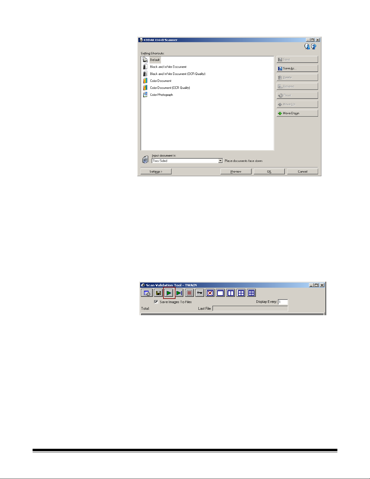
1. Select Start>Programs>Kodak>Document Imaging>Scan
Validation Tool or click the Scan Validation Tool icon.
The Scan Validation Tool dialog box will be displayed.
2. Select TWAIN (or ISIS) for the Driver Types and Kodak Scanner
i1410/i1420/i1440 as the driver. The Scan Validation Tool dialog box
will be displayed.
NOTE: For a description of this window and toolbar buttons, see
the section entitled, “Scan Validation Tool dialog box” in
Chapter 4.
3. Click one of the window icons to open and display the scanned
images.
4. Click the Setup icon.
A-61550 May 2007 19
Page 25
The main Kodak Scanner window will be displayed.
5. Select the Default Setting Shortcut.
6. Click OK. This resets the software to the factory-installed default
settings. The factory default settings are set to capture black and
white images. For an i1410 Scanner one side of the document will
be scanned. For an i1420 or i1440 Scanner both sides of the
document will be scanned. The Scan Validation Tool screen will be
displayed.
7. Place some test documents into the input tray of the scanner. If you
are scanning one-sided documents or if you have a Kodak i1410
Scanner, be sure the side you want to scan is facing the input tray.
8. Click the Start Scanning icon on the Scan Validation Tool.
20 A-61550 May 2007
Page 26
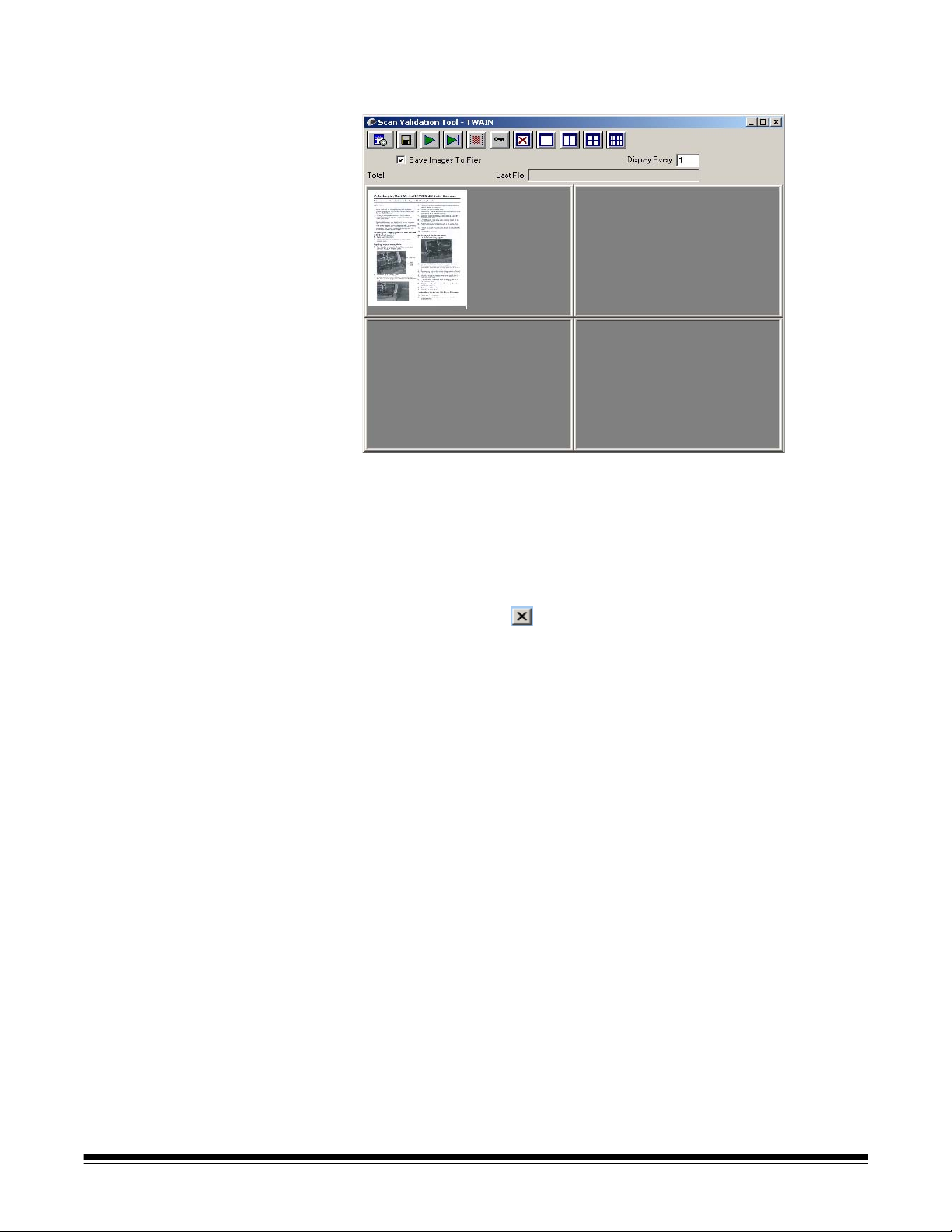
The documents will be scanned and displayed in the Scan
Validation Tool window.
NOTE: If the scanner is in power saver mode, a message will be
displayed that the lamps need sufficient time to warm up.
Scanning will proceed when the lamps are ready.
After the images have been displayed, your scanner installation
verification is completed.
9. Click the Close box to exit the Scan Validation Tool.
Viewing test images The images you scanned can be found in the TWAIN folder on the C
drive. Files will be named using the following naming convention:
image0000001A.jpg is a front image; image0000001B.jpg is a back
image. Double-click on this file to open and view the captured image.
Because factory default settings were used, the image may not be
optimized to meet your needs.
When testing has been completed, delete the test images.
A-61550 May 2007 21
Page 27
Smart touch functionality
Smart touch functionality allows you to quickly and easily perform
common scanning tasks. Predefined tasks are installed with the
scanner, however, you can configure smart touch to handle the tasks
that are most important to you. You can perform any of the tasks by
selecting the function from the smart touch function listing. Nine
different functions can be assigned and performed.
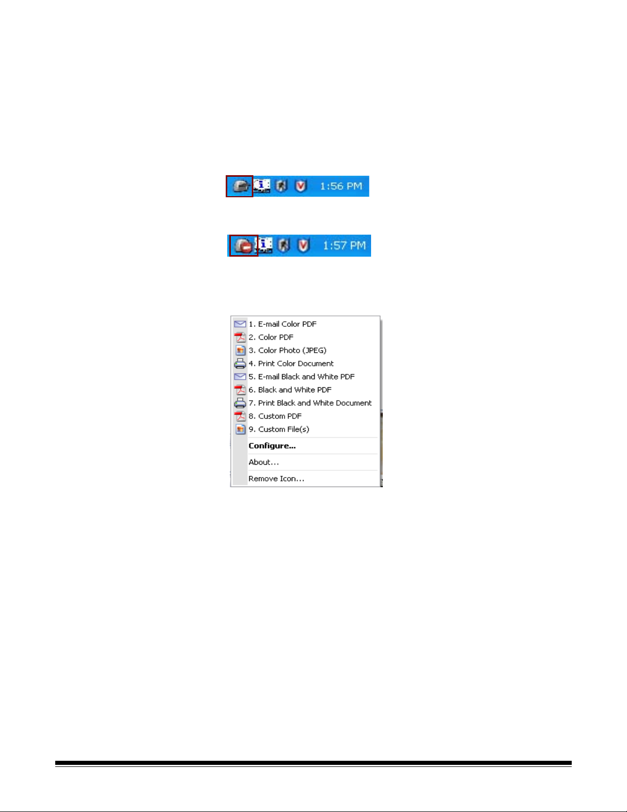
After the scanner, software drivers, and application software are
properly installed and the PC has been restarted, a Scanner icon will be
displayed on the system tray.
NOTE: If the Scanner icon indicates that the scanner is not ready, turn
the scanner off, and then on again.
• Click on the Scanner icon on the system tray to display the smart
touch function listing. This list displays the currently configured
functions.
Function listing — click on one of the functions to run the assigned
task.
Configure — select Configure to change the task assigned to a
function.
About — displays the version number and information about smart
touch.
22 A-61550 May 2007
Page 28
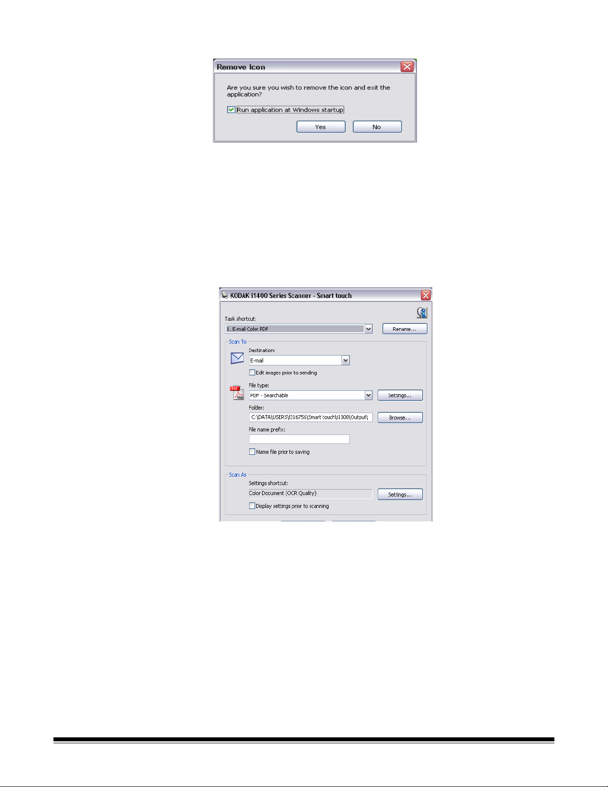
Remove Icon — displays the Remove Icon dialog box.
When you click Yes, you will close smart touch and remove the smart
touch icon from the system tray.
The software can be started manually by selecting Start>Programs>
Kodak>Document Imaging>i1410,i1420,i1440 >Smart touch.
Configuration dialog box The Configuration dialog box allows you to change the tasks associated
with each of the 9 function numbers.
When you select Configure from the function listing, the Configuration
dialog box will be displayed.
Task shortcut — select the function (1 through 9) that you want to
modify.
Rename — displays the Rename dialog box which allows you to enter
a new name for the Task shortcut.
A-61550 May 2007 23
Page 29
Scan To settings Destination — allows you to select one of the following options:
• File: creates an electronic file from the scanned documents and
saves it in the location specified in the Folder path.
• Application: creates an electronic file from the scanned documents
and launches the application program for the saved file. For example,
if your system is set up to use Adobe Reader to read PDF files, the
saved file will be opened using Adobe Reader.
• E-mail: creates an electronic file from the scanned documents and
launches your default E-mail program with the saved file included as
an attachment.
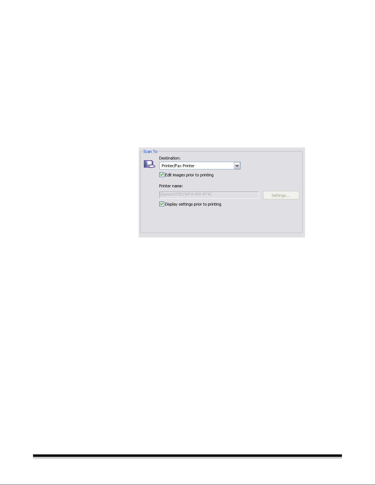
• Printer/Fax Printer: sends the scanned documents to the printer or
fax printer.
NOTE: If you select Printer/Fax Printer, the Scan To options
change.
- Display settings prior to printing: if selected, the Print dialog
box will be displayed after the document(s) are scanned, allowing
you to select the printer and set the print options. The Print dialog
box will be displayed each time the function is run.
- Settings: displays the Print dialog box allowing you to select a
different printer or different set of print options for this function.
These settings will be saved and used by default each time the
function is run. This option is not available if Display settings
prior to printing is checked.
Edit images prior to saving/emailing/printing: if selected, the
scanned images will be displayed in an Edit window to allow for editing.
File Type — select one of these options based on how you want to
save or send the scanned image(s). Available formats are:
• PDF: Adobe PDF files (Portable Document Files) look exactly like
original documents and preserve the fonts, images, graphics and
layout of the source files regardless of the application and platform
used to create it.
• PDF - Searchable: same as a PDF file with the addition of full text
search features for locating words.
• RTF (Rich Text Format): is a document file format developed by
Microsoft to allow easy portability from one PC to another regardless
of the operating system that is running on the PC.
24 A-61550 May 2007
Page 30
• JPEG/TIFF - Single page: if you are scanning documents with
multiple pages or sides, each page or side is saved as a separate
JPEG or TIFF file.
• TIFF - Multi-page: combines all the scanned images into a single
TIFF file.
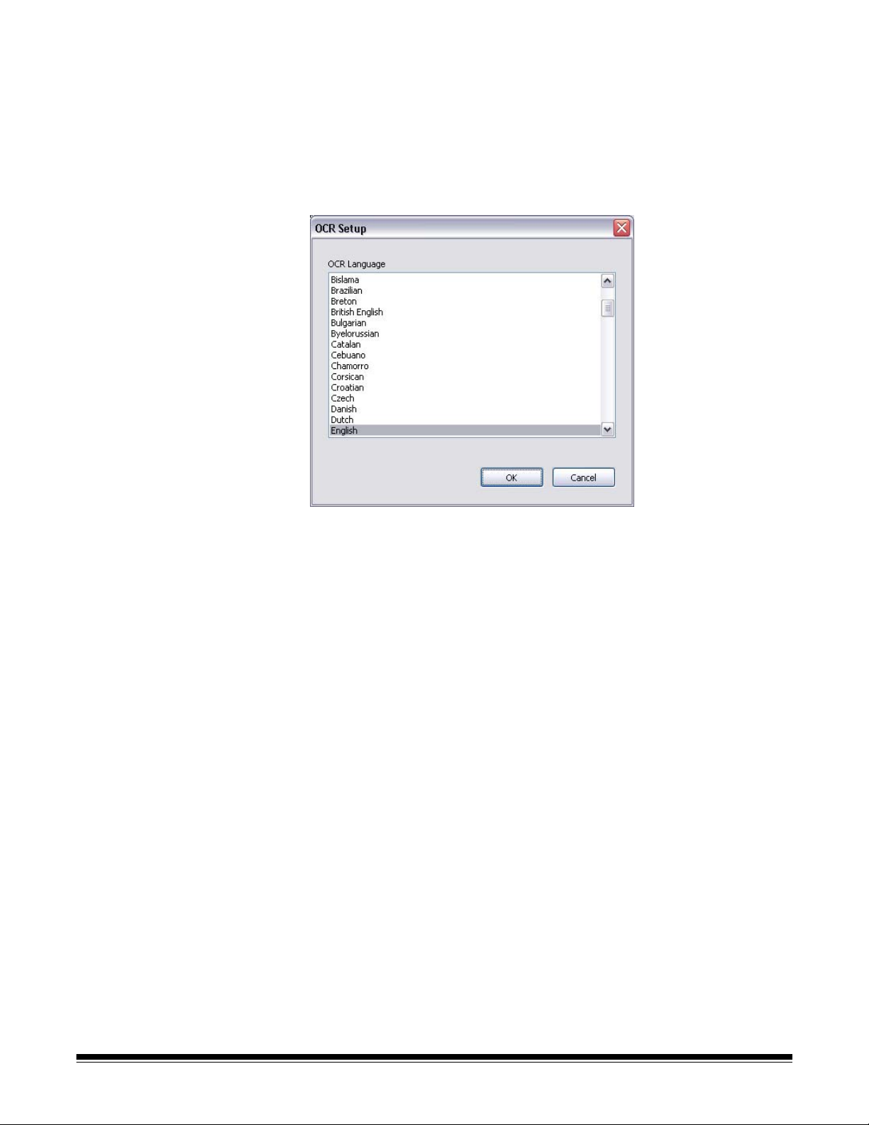
Settings button — if you select PDF - Searchable or RTF as the File
Type, the OCR Setup dialog box will be displayed.
• Select the language for the searchable PDF or RTF file and click OK.
Folder: enter the folder name where you want to save the scanned
images or click Browse to locate the folder.
File Name Prefix: when images are scanned, they are automatically
assigned a unique file name. For example, if you choose to scan your
documents as PDF files, the software automatically assigns the date
and sequence number for each image: 2006-09-27(1).pdf (for the first
PDF file created), 2006-09-27(2) for the second PDF file created, etc. If
you want to add a prefix to the file name, it will be attached to the
beginning of each file name. For example, if you want the word Invoice
before the file name, enter “Invoice” in the File name prefix field. The
files will be named: Invoice2006-09-27(1); Invoice2006-09-27(20), etc.
Name file prior to saving: if selected, the Save As dialog box will be
displayed after the document(s) are scanned, allowing you to select the
specify the name of the file and the location where it will be stored. The
Save As dialog box will be displayed each time the function is run.
A-61550 May 2007 25
Page 31

Scan As settings Setting Shortcut — displays the name of the Setting Shortcut used on
the main Kodak Scanner window. This is the shortcut to the collection
of scanner settings being used by the scanner.
Display settings prior to scanning: if selected, the main Kodak
Scanner window will be displayed before the document(s) are scanned,
allowing you to select the scanner Setting Shortcut. The main Kodak
Scanner window will be displayed each time the function is run.
Settings: displays the main Kodak Scanner window allowing you to
select a different Setting Shortcut for this function. The new Setting
Shortcut will be saved and used by default each time the function is run.
OK — closes the Configuration dialog box. If you made changes in the
Configuration dialog box and you did not save your changes, a
message will be displayed.
Cancel — closes the Configuration dialog box without saving any
unapplied changes.
Yes — saves any changes made on the Configuration dialog box.
No — closes the Configuration dialog box without saving any changes.
26 A-61550 May 2007
Page 32

Configuring function numbers
1. Click the smart touch icon on the system tray to display the smart
touch function listing and select Configure.
The Configuration dialog box will be displayed.
2. Select the Task shortcut you want to configure from the Ta s k
Shortcut drop-down list.
3. If you want to rename the Task Shortcut, click Rename. The
Rename dialog box will be displayed.
• Enter the desired name and click OK.
4. Select the desired destination from the Destination drop-down list.
5. Select the desired file type from the File Type drop-down list. This
determines the file type of the electronic file to be created.
A-61550 May 2007 27
Page 33

6. By default your documents will be stored within your “My
Documents” folder. If you want to change it, enter the folder name or
click Browse to select a different folder.
7. If desired, add a file name prefix by entering the text in the File
name prefix field.
8. If you want to provide your own file name for the file, select the
Name file prior to saving check box on the Configuration dialog
box.
9. If desired, select a different Setting Shortcut based on the type of
document you are scanning by selecting the Settings button on the
main Kodak Scanner window.
10.If you want to change your scanner Setting Shortcut before
scanning, check Display settings prior to scanning from the
smart touch Configuration dialog box.
11. Click Apply.
12.Modify other function numbers by repeating Steps 2 and 11.
13.When finished, click OK.
28 A-61550 May 2007
Page 34

Smart touch Edit window The smart touch Edit window allows you to view the scanned images
before sending them to the final destination. As documents are
scanned, the images will be displayed in the Edit window.
From this window you can perform common editing tasks such as,
rotating and deleting blank pages, etc. When finished, click Done to
send the images to the final destination.
To enable this Edit window, select the Edit images prior to sending
check box on the Configuration dialog box for the function you are
configuring.
A-61550 May 2007 29
Page 35

These icons are available on the Edit window. To use a tool, click on the
icon and apply it to the desired image.
Start — allows you to scan additional documents and append
them to the current images.
Stop — cancels the scanning of documents.
Magnifier — magnifies a portion of the image. Press and hold
the left mouse button inside an image to magnify it. Drag the tool
across the image to magnify different areas of the image.
Pan — allows you to move the image freely around the window.
Use this tool when the entire image is not visible in the display
window, for example after zooming in.
Rotate 90 — rotates the image 90 degrees to the right.
Rotate 180 — rotates the image 180 degrees to the right.
Rotate 270 — rotates the image 270 degrees to the right.
Delete — deletes the selected image. A confirmation dialog box
will be displayed before the image is deleted.
Select Region — allows a rectangular region to be drawn in
each image. Use this tool with the Crop and Blank tools. Click on
the icon in the lower left corner of an image to remove (deselect)
the region.
Crop — crops the image, keeping only the portion of the image
inside the region. A confirmation dialog box will be displayed
before the image is cropped.
Blank — replaces the portion of the image inside the region with
a white background. A confirmation dialog box will be displayed
before the image is modified.
More Editing Tools — these are tools and shortcuts to get
different views of the images, including tools to zoom in and
zoom out. Normally the shortcuts (or hotkeys) would be used for
these tools.
Done — click this icon when you have finished viewing or editing
the images and you want to send them to the selected
destination.
Using function numbers When you have assigned the function numbers, they can be easily
launched from the smart touch function listing.
1. Display the function listing from the smart touch icon on the system
tray.
2. Select the function number you want to run.
30 A-61550 May 2007
Page 36

Scanning your
Standard paper size documents should feed easily through the scanner.
documents
• Place the documents you want to scan into the input tray of the
scanner. If you are scanning one-sided documents or if you have a
Kodak i1410 Scanner, be sure the side you want to scan is facing the
input tray.
Automatic feeding To scan a batch of documents, follow the guidelines for size, type,
quantity, etc., as previously described in the “Document preparation”
section. For faster throughput, feed documents into the automatic
document feeder in landscape orientation (longer side as the leading
edge).
IMPORTANT: Remove all staples and paper clips before scanning.
Staples and paper clips in documents may damage the
scanner.
1. Align the leading edges of the stacked documents.
2. Position the documents face down with the leading edge centered
in the automatic document feeder.
3. Adjust the input tray side guides.
4. Adjust the output tray position, if necessary.
5. Pull out the output tray extender, if necessary.
6. Start scanning.
A-61550 May 2007 31
Page 37

Continuous feeding Continuous feeding allows you to place additional batches of
documents in the feeder for “infinite” feeding (with operator assistance).
• When only a few documents from one batch remain in the feeder,
place the next batch face down on top of those documents.
Manual feeding Follow the guidelines for document size, type, weight, quantity, etc.
Position the documents face down with the leading edge centered
in the automatic document feeder, then start scanning.
Damaged documents You can scan torn or fragile documents through the automatic
document feeder if they are placed in a protective plastic sleeve.
1. Position the sleeve face down, folded edge first, and centered in
the automatic document feeder.
2. Lift the gap release lever, if necessary (this provides more clearance
to ease document feeding).
3. Start scanning.
32 A-61550 May 2007
Page 38

4 Image Processing
Overview This chapter introduces concepts that may be new to some users. The
Kodak i1400 Series Scanners provide the ability to process scanned
images to improve their quality. Using these features the scanner can
sometimes make the scanned image look better than the original
document. Basic image processing concepts are reviewed in this
chapter to help you take advantage of these features.
Image processing refers to several separate features of the scanner
that allow you to automatically adjust each image in a certain way that
may improve the resulting images. Common examples of image
processing features are correcting any skew in the fed document,
cutting the edges of the image off to remove any unneeded border or
cleaning up extraneous “noise” on the image. This can be done
automatically so you can get better images with minor rework.
The information that follows describes the image processing features.
The same options should be available on the user interface of the
scanning application you are using (i.e., Kodak Capture Software).
Terminology and features
Starting the Scan Validation Tool
If you have used previous scanners from Kodak, you may be familiar
with the image processing features already. With the new graphical
user interface in the TWAIN datasource, some of the names of those
features have changed. Refer to Appendix B, TWAIN Image
Processing Terminology for a cross reference of previous names with
new names.
1. Select Start>Programs>Kodak>Document Imaging>Scan
Validation Tool.
2. Select TWAIN (or ISIS) for the Driver Type and the Kodak Scanner
i1410/i1420/i1440 Scanner as the driver.
The Scan Validation Tool dialog box will be displayed.
A-61550 May 2007 33
Page 39

The Scan Validation Tool dialog box
The Scan Validation Tool (SVT) is a diagnostic application provided by
Kodak. The SVT user interface allows access to all the features of the
scanner and is a good way to verify that the scanner is working
properly. The Scan Validation Tool allows you to verify scanner
functionality using both the TWAIN datasource and the ISIS driver.
Toolbar buttons
Setup — displays the user interface for the selected driver.
Destination — allows you to select a directory to store scanned
images and their file names. This option is only available when
Save Images to Files is selected.
Start Scanning — scans the documents in the input tray.
Scan One Page — scans only one page.
Stop Scanning — ends the scan session.
License Key — displays the License Key window
No Image Display mode — closes the Image Viewer window
(no images will be displayed).
One Image Display mode — displays one image at a time.
Two Image Display mode — displays two images at a time.
Four Image Display mode — displays four images at a time.
Eight Image Display mode — displays eight images at a time.
34 A-61550 May 2007
Page 40

Save Images to Files — when selected, will save the images to the
specified directory.
Display Every enter the sampling rate of the images you want to
display while scanning. For example, to see every image, enter a value
th
of 1. To see every 10
image, enter a value of 10.
Total displays the total number of images scanned during the current
Scan Validation Tool session.
• To access the TWAIN datasource (or ISIS driver), double-click the
Setup icon on the Scan Validation Tool dialog box to access the main
Kodak Scanner window.
Last File displays the full path and file name for the last stored
image.
A-61550 May 2007 35
Page 41

Using the TWAIN datasource
The Kodak i1400 Series Scanners can provide a wide variety of
electronic images. This can be done by using the TWAIN datasource
Kodak provides in concert with your scanning application. The TWAIN
datasource is the part of the capture system which links the scanner to
your scanning application.
When using the TWAIN datasource, the main Kodak Scanner window
will display a list of Setting Shortcuts. Each Setting Shortcut is a group
of specific image and device settings. The supplied Setting Shortcuts
represent some common electronic image outputs used for a wide
variety of input documents. If none of the Setting Shortcuts meet your
scanning needs, you can create a customized Setting Shortcut. For
example, you could create a Setting Shortcut called “Invoices” and
whenever you want to scan invoices, you simply select that Setting
Shortcut. For more information, refer to the sections entitled, “Creating
a new Setting Shortcut” and “Changing image settings” later in this
chapter.
For the purpose of this manual, all displayed dialog boxes assume the
features available on the Kodak i1420 and i1440 Scanners (duplex
scanner). If you have a Kodak i1410 Scanner (simplex scanner) all
options are limited to one-sided scanning only.
How do I begin? The goal is to make scanning as simple as possible. This is
accomplished by selecting a Setting Shortcut from the main Kodak
Scanner window and then selecting OK/Scan.
The scanner comes with some Setting Shortcuts already defined. In
most cases, you will find that these shortcuts are all you will need. If you
find that you need different settings, then you should create your own
Setting Shortcut. Your shortcut will be added to the list of Setting
Shortcuts and available for all future scanning.
Most of the options you will want to set are available on these two
windows:
• Image Settings: clicking the Settings button on the main Kodak
Scanner window, displays the Image Settings window. From this
window you can set your image processing parameters by using the
General, Size, Adjustments and Enhancements tab. You can also
access the Device settings, by clicking the Device button or the
Advanced settings by clicking the Advanced Image Setup icon.
• Device Settings: the Device button is located on the Image Settings
window. When you select Device, you will have access to the
General and Multifeed tabs (and Printer tab if you have the document
printer installed). From the Device Settings window, you can also
access Diagnostics.
36 A-61550 May 2007
Page 42

The procedures that follow describe how to configure a customized
Setting Shortcut. Complete descriptions of the features and options on
the Kodak Scanner window and tabs are found in the section entitled,
“The main Kodak Scanner window”.
NOTE: Setting Shortcuts can sometimes be overridden by your
scanning application. If this happens, the shortcut you call will
appear in the main Kodak Scanner window in italics with the
word <Changed> next to it. This is normal behavior for an
application that does not use Setting Shortcuts and downloads
its preferred individual settings to the scanner first and then
provides access to the TWAIN datasource.
When you click OK to begin scanning, you will be asked if you
want to save the changed settings. When using an application
that does not use Setting Shortcuts, select No to this prompt
and continue scanning.
Selecting Image settings
From the main Kodak Scanner window:
1. Select a predefined Setting Shortcut from the Setting Shortcuts list.
Choose a Setting Shortcut that describes as closely as possible the
image output you desire.
2. Determine if you want to capture an electronic image of the front of
your document, back of your document or both sides of your
document and make the selection from the Input document is dropdown list. Options are:
• Two Sided — captures both sides of the document
• One Sided-Front — captures the front side only
• One Sided-Back — captures the back side only
A-61550 May 2007 37
Page 43

3. Place one or two representative documents in the input tray of the
scanner.
NOTE: When scanning one side of a document or if you are using
an i1410 Scanner, be sure to place the side of the
document to be scanned facing the input tray.
4. If you want to see what your selected image processing options will
look like and make on-screen changes, click Preview to review and
adjust the image.
NOTE: This only needs to be done if you want to make interactive
adjustments to your selected image processing options.
5. If you are satisfied with your selected image processing options,
reload your document if necessary and click OK/Scan.
• If the images are acceptable, the image processing settings are
fine and you do not need to click the Settings button to alter any
values in the General, Size, Adjustments or Enhancements tabs.
• If the images are not acceptable, you can either select a different
predefined Setting Shortcut that more closely describes your
desired output or you can continue to work with the Setting
Shortcut you have selected by reviewing each setting on the
General, Size, Adjustments and Enhancements tabs and make
the appropriate changes. When you make any changes, repeat
Steps 3 - 5 to until you get the desired results.
6. If you made any changes to a predefined default Setting Shortcut,
click Save As on the main Kodak Scanner window. The Save As
dialog box will be displayed.
7. Enter a new Setting Shortcut name that is meaningful to you and
click Save. You have now created and saved a custom Setting
Shortcut which can be used for your scanning operations.
38 A-61550 May 2007
Page 44

Selecting Device
1. Select the Setting Shortcut that you just created.
settings
2. Select Settings to access the Image Settings window.
3. Select Device. The Device Settings window will be displayed.
4. Before making any adjustments, click through the tabs on the
Device Settings window to get familiar with features that are
available. See the section entitled, “The Device Settings window” for
information about these features.
5. Determine which features you want to use when scanning and
select the appropriate tab.
6. On each tab, select the appropriate options or action you want the
scanner to perform.
7. When finished:
• Click Home to return to the main Kodak Scanner window and
click Save to save your selections to your custom Setting
Shortcut, or
• Click Image to return to the Image Settings window if you need to
make additional changes.
A-61550 May 2007 39
Page 45

The main Kodak Scanner window
The main Kodak Scanner window is the home window of the scanner’s
user interface. You can scan by simply selecting a Setting Shortcut and
then selecting OK/Scan.
Setting Shortcuts — provides a listing of the Setting Shortcuts
currently set up. The supplied shortcuts are:
• Default — the scanner’s default settings
• Black and White Document
• Black and White Document (OCR Quality)
• Color Document
• Color Document (OCR Quality)
• Color Photograph
NOTES:
• Select an OCR Quality shortcut if you want to have the electronic
images processed by an OCR application.
• These Setting Shortcuts are provided at installation and are read-only
shortcuts. They can be used as models to create your custom
shortcuts, but cannot be modified.
40 A-61550 May 2007
Page 46

• If you have made changes to a Setting Shortcut and have not saved
your changes, the Setting Shortcut will be appended with the text
<changed>, and the name will be displayed in italics
(e.g., *Default<changed>).
Input document is — allows you to select which sides of the document
has information that you want an electronic image of.
• Two Si d ed: scans the front and back of the document.
• One Sided - Front: scans only the front side of the document.
• One Sided - Back: scans only the back side of the document.
NOTES:
• Be sure to place your documents face down in the input tray.
• The Two Sided and One Sided - Back options are only available for
duplex scanner models.
A-61550 May 2007 41
Page 47

Save — saves any changes made to the selected Setting Shortcut.
Save As — displays the Save As window allowing you to save your
current settings with a new Setting Shortcut name.
Delete — deletes the selected Setting Shortcut; you will be prompted
for confirmation. This is only available for shortcuts you have created.
Rename — allows you to rename the selected Setting Shortcut. This is
only available for shortcuts you have created.
Reset — allows you to undo any changes that have been made to the
selected Setting Shortcut. This is only available for shortcuts you have
modified (e.g., are in italics and appended with <changed>).
Move Up — moves the selected Setting Shortcut up one position in the
Setting Shortcut list. When you move a Setting Shortcut, it will stay in
that position until you move it again.
Move Down — moves the selected Setting Shortcut down one position
in the Setting Shortcut list. When you move a Setting Shortcut, it will
stay in that position until you move it again.
Settings — displays the Image Settings window which allows you to
make changes to the selected Setting Shortcut. From this window you
can also access the Device settings and Diagnostic windows.
Preview — initiates a scan and then displays the Image Settings
window with the scanned image placed in the preview area. The image
displayed is a sample based on your current shortcut settings.
OK/Scan — when selected, you will be prompted to save any unsaved
changes.
NOTE: If this button is OK, any unsaved changes will remain in effect
for the current scan session.
Cancel — closes the main Kodak Scanner window without saving any
changes.
Information Icons
About: displays the scanners’ version and copyright information.
Help: displays help information for the window currently being
displayed.
42 A-61550 May 2007
Page 48

The Image Settings window
From this window you can define image processing options by using
the available tabs. The values used in Image Settings are saved in the
selected Setting Shortcut. The Image Settings window includes the
following tabs: General, Size Adjustments and Enhancements.
Side — allows you to select which side and image to configure (e.g.,
Front, Back, Both: Color (24-bit), etc.). All image settings will be applied
to the selected image.
NOTES:
• The Side option is only available when advanced settings have been
selected on the Advanced tab.
• The Both and Back options are only available for duplex scanner
models.
Advanced Image Setup: displays the Advanced tab.
A-61550 May 2007 43
Page 49

Toolbar buttons
Zoom In: enlarges the image that is currently being displayed in
the preview area.
Zoom Out: reduces the image that is currently being displayed
in the preview area.
Rotate Outline: rotates the outline 90 degrees.
NOTE: This is only available if the rotated outline fits in the
scanner’s maximum width.
Center Outline: adjusts the X origin of the outline such that the
outline is centered within the scanner’s maximum width.
Preview Quality: selects the quality of the scanning image.
• Normal: displays acceptable image quality at a lower
resolution.
• High: displays the most accurate representation of the actual
image. The image that is displayed in the preview area is a
good representation of what the final image will look like.
Units: selects the unit of measurement for the scanner; this
includes the preview area and any size-related options. The
Units options are: Inches, Centimeters and Pixels.
Preview area The main purpose of the preview area is to display a sample image that
is based on your current shortcut settings. An image will be displayed in
this area after a preview scan has been performed. The displayed
image will automatically show the effects of your changes, in most
cases, without having to rescan the document. If a rescan is necessary,
you will be prompted to reinsert the document.
NOTE: If you choose Document: Manually Select or Image: Part of a
document on the Size tab, the preview area will also show the
current Outline selections.
Home — returns you to the main Kodak Scanner window.
Device — displays the Device Settings window.
Preview — initiates a scan and places the image in the preview area.
The image displayed is a sample based on your current shortcut
settings.
OK/Scan — when selected, you will be prompted to save any unsaved
changes.
NOTE: If this button is OK, any unsaved changes will remain in effect
for the current scan session.
Cancel — closes the main Kodak Scanner window without saving any
changes.
44 A-61550 May 2007
Page 50

General tab The General tab contains commonly used image options. In most
cases, you will not have to change options on other tabs.
Scan as — allows you to select the electronic image format.
• Color (24-bit): produces a color version of your document.
• Grayscale (8-bit): produces a grayscale version of your document.
• Black and white (1-bit): produces a black and white version of your
document.
NOTE: The Scan as option is only available when Images per side:
One is selected on the Advanced tab.
Document type — allows you to select the type of content on your
documents.
• Text with Graphics: the documents contain a mix of text, business
graphics (bar graphs, pie charts, etc.) and line art.
• Text: the documents contain mostly text.
• Text with Photographs: the documents contain a mix of text and
photographs.
NOTE: This option is not available for all models.
• Photographs: the documents contain mostly photographs.
Media type — allows you to select the type of paper you are scanning,
based upon the texture/weight. The options are: Plain Paper, Thin
Paper, Glossy Paper, Card Stock, and Magazine.
Resolution — allows you to select the dots per inch (dpi), which is a
determinant of a better quality image. It may also increase scanning
time and image size. The options are: 75, 100, 150, 200, 240, 300, 400,
600 and 1200 dpi.
A-61550 May 2007 45
Page 51

Compression — allows you to reduce your electronic image size.
• Type: the scanner will produce a color version of your document.
- (none): no compression, which may produce a large image size.
- Group-4: uses a CCITT standard to compress a black and white
image, often used in conjunction with TIFF files.
- JPEG: uses JPEG techniques to compress a color/grayscale
image.
• Quality — if you choose JPEG compression, select one of the quality
options:
- Draft: maximum compression which produces the smallest image
size.
- Good: a fair amount of compression but still produces acceptable
image quality.
- Better: some compression which produces decent image quality.
- Best: minimal compression which produces very good image
quality.
- Superior: the least amount of compression which produces the
largest image size.
46 A-61550 May 2007
Page 52

Size tab
Document — allows you to select how the scanner will detect your
document as it is being fed through the scanner.
• Automatically Detect and Straighten: the scanner will
automatically find each document (regardless of size) and will
straighten any document that may have been fed crooked.
• Automatically Detect: the scanner will automatically find each
document (regardless of size). If a document is fed crooked, it will not
be straightened.
• Photograph: the scanner will locate the photograph on the
document and return an image that contains just the photograph. If
the scanner finds more than one photograph on a document, one
image is still returned.
NOTE: This option is not available for all models.
• Manually Detect: the scanner will return an image based on the area
you specify with the Outline options. It is suggested that you only use
this option for scan jobs that contain same-size documents.
• Continuous: the scanner will split the document into separate
images based on the area you specify with the Outline options. It is
suggested that you select an Outline that covers the entire width of
the document and a height around 11 inches (297 mm).
NOTE: This option is not available for all models.
A-61550 May 2007 47
Page 53

Image — allows you to select which part of the document you want to
use for creating your electronic image.
• Entire document:
- if you select Document: Automatically Detect and Straighten,
Document: Automatically Detect or Document: Manually
Detect, returns the entire document.
- if you select Document: Photograph, the entire document is
used to locate the photograph.
• Part of the document:
- if you select Document: Automatically Detect and Straighten
or Document: Continuous, returns the portion of the document
which you specify with the Outline options.
- if you select Document: Photograph, only the portion of the
document which you specify with the Outline options will be used
to locate the photograph.
Outline — allows you to select the location and size to use for creating
your electronic image. The preview area will show the outline.
• Origin (x, y):
- if you select Document: Automatically Detect and Straighten
or Document: Photograph, (x) is the distance from the left edge
of the document and (y) is the distance from the top edge of the
document.
- if you select Document: Manually Select or Document:
Continuous, (x) is the distance from the left edge of the
scanner’s paper path and (y) is the distance from the first portion
of the document detected by the scanner.
• Size (w, h):
- if you select Document: Automatically Detect and Straighten
or Document: Manually Select, this is the width and height of
the electronic image.
- if you select Document: Photograph, this is the width and height
of the area of the document to use to locate the photograph.
- if you select Document: Continuous, this is the width and height
of each separate electronic image.
NOTE: The electronic image may be shorter than you specified if the
outline goes beyond the end of the scanned document.
• Angle: allows you to select the angle of the outline.
• Predefined sizes: provides a list of commonly used paper sizes.
Selecting an item in this list will automatically set the size of the
outline to that paper’s size. Custom will be displayed when the
outline size does not match any sizes in the list.
NOTE: You can also adjust the outline displayed in the preview area
using your mouse.
48 A-61550 May 2007
Page 54

Border — allows you to select what action to perform on the edges of
your electronic image.
• (none)
• Add: includes up to approximately 0.1 inches of border around all of
the image edges.
NOTE: This option is only available for the following selections: when
both Document: Automatically Detect and Straighten and
Image: Part of Document are selected; Document:
Automatically Detect; or Document: Manually Select.
• Remove: produces an image that contains just the document by
eliminating any residual border. Residual border can be caused by
variations in a document edge; for example, when a document is not
a perfect rectangle and/or was fed crooked.
NOTES:
• While this option will not remove large amounts of residual
border, there is a possibility that a small amount of the document
will be lost.
• This option is only available when both Document:
Automatically Detect and Straighten and Image: Entire
Document are selected.
A-61550 May 2007 49
Page 55

Post-scan rotation options — allows you to select any rotation to be
applied to the electronic image after is has been scanned.
• (none)
• Automatic — the scanner will analyze each document to determine
how it was fed and will rotate the image to the proper orientation.
• 90, 180, 270 degrees — the amount of rotation that will be
performed.
The following example shows how these settings effect a document
that was fed landscape:
Landscape Feed
Orientation
90
degrees
180
degrees
270
degrees
50 A-61550 May 2007
Page 56

Adjustments tab: black and white
The options available on the Adjustments tab depend on the Scan as
selection on the General tab. The following options are based on a
Scan as selection of Black and White.
Conversion quality — these settings effect how the scanner analyzes
a grayscale version of the document which is used to produce the black
and white electronic image.
• Best (iThresholding): the scanner analyzes each document to
produce the highest quality image. This option allows scanning of
mixed documents with varying quality (i.e., faint text, shaded
backgrounds, color backgrounds) and when scanning with consistent
document sets.
• Normal (ATP): allows you to determine the optimal settings to
produce the desired image quality. This option works best when
scanning with consistent document sets. You may also want to use
this option if you have difficult documents such that you cannot find a
Contrast setting for Best that produces the desired quality.
• Draft (Fixed): allows you to select the grayscale threshold used to
determine if a pixel is black or white. This option works best for high
contrast documents.
Contrast — allows you to make an image sharper or softer. Decreasing
this setting will make the image softer and reduce noise in the image.
Increasing this setting will make the image clearer and make light
information more visible. The options range from -50 to 50. The default
is 0.
NOTE: This is not available for Conversion quality: Draft.
A-61550 May 2007 51
Page 57

Threshold — aids in controlling the level at which a pixel is considered
black or white. Decreasing this setting will make the image appear
lighter, and can be used to subdue background noise. Increasing this
setting will make the image appear darker, and can be used to help pick
up light information. This options range from 0 to 255. The default is 90.
NOTE: This is not available for Conversion quality: Best.
Filters
• Noise
-(none)
- Lone Pixel: reduces random noise by converting a single black
pixel to white when it is completely surrounded by white pixels or
by converting a single white pixel to black when it is completely
surrounded by black pixels.
- Majority Rule: sets each pixel based on its surrounding pixels.
The pixel will become white if the majority of the surrounding
pixels are white and visa versa.
•Image
-(none)
- Halftone Removal: enhances dot matrix text and images with
halftone screens (e.g., newspaper photographs).
Invert Colors — allows you to select how the black pixels will be stored
in the image. By default the black pixels are stored as black and the
white pixels are stored as white. Turn this option on if you want the
black pixels stored as white and the white pixels stored as black.
NOTE: You may want to change this option if your application
misinterprets the image data and stores your image in reverse
of what you expect.
52 A-61550 May 2007
Page 58

Adjustments tab: color or grayscale
The options available on the Adjustments tab depend on the Scan as
selection on the General tab. The following options are based on a
Scan as selection of Color or Grayscale.
Brightness — changes the amount of white in the color or grayscale
image. The values range from -50 to 50. The default is 0.
Contrast — makes the image sharper or softer. The values range from
-50 to 50. The default is 0.
Red — changes the amount of red in the color image.The values range
from -50 to 50. The default is 0. Does not apply to grayscale images.
Green — changes the amount of green in the color image. The values
range from -50 to 50. The default is 0. Does not apply to grayscale
images.
Blue — changes the amount of blue in the color image. The values
range from -50 to 50. The default is 0. Does not apply to grayscale
images.
Background Smoothing — using this option for documents or forms
with a background color will help produce images with a more uniform
background color. This option improves image quality and may reduce
file size.
• Method:
- (none) - no background smoothing will be performed.
- Automatic - smooths up to three background colors.
- Change to White - identifies up to three background colors and
substitutes each color with white.
A-61550 May 2007 53
Page 59

• Apply to:
- Predominant - smooths the predominant background color to
white.
- Neutral - smooths only the neutral color to white, and also smooths
up to two additional background colors.
- All - smooths the neutral color and up to two additional background
colors to white.
NOTE: The Apply to options are only available for Method: Change
to White.
• Aggressiveness: allows you to adjust the extent at which the
background(s) are determined. The values range from -10 to 10. The
default is 0.
54 A-61550 May 2007
Page 60

Enhancements tab The options on the Enhancements tab depend on the Scan as selection
on the General tab.
Image Edge Fill — fills the edges of the final electronic image by
covering the area with the specified color.
• Color: allows you to select the color to fill the edges with.
- (none)
-White
-Black
• All sides match: when turned on, an equal amount will be filled in on
all sides.
• Top: determines how much of the top edge will be filled in.
NOTE: This option is applied to all edges when All sides match is
turned on.
• Left/Right: the option on the left will determine how much of the left
edge will be filled in and the option on the right will determine how
much of the right edge will be filled in.
• Bottom: determines how much of the bottom edge will be filled in.
NOTE: When using Image Edge Fill, be careful not to enter a value
too large as it could fill in image data that you want to keep.
A-61550 May 2007 55
Page 61

Blank Image Detection — allows you to configure the scanner to not
include blank images.
• On: turns Blank Image Detection on and makes the rest of the Blank
Image Detection options available.
• Delete if file size is less than: allows you to select the minimum
image size that the scanner will consider to be non-blank. Any image
that is less than this value will be considered blank and will not be
given to the scanning application. The values range from 1 to 1000
KB (1 KB equals 1024 bytes).
Color Dropout — used to eliminate a form's background so that only
the entered data is included in the electronic image (i.e., remove the
form’s lines and boxes). For black and white images, these settings
effect the grayscale version of the document which the scanner
analyzes to produce that electronic image.
• Color: select the desired dropout color.
- (none)
-Red
-Green
-Blue
NOTE: For i1440 Scanners only: If you created custom dropout
colors, these colors will also be available in the Color dropdown list.
The following options are for the Kodak i1440 Scanner only.
• Form data is color: allows you to indicate that a color other than
black or dark blue ink, was used for the data entered on the form.
• Configure: displays the Color Dropout Configuration window, which
allows you to create and change custom dropout colors. If you have
any unsaved changes for the current Setting Shortcut, you will be
prompted to save those changes.
NOTE: The Color Dropout options are only available when the Scan
as selection is Black and White or Grayscale.
56 A-61550 May 2007
Page 62

Defining custom dropout colors using the Color Dropout Configuration window
The Color Dropout Configuration window allows you to define custom
dropout colors. If the supplied dropout colors (i.e., red, green, blue) do
not dropout the color on your form, you can create a custom dropout
color that is specific to your form. The custom color is created by using
the Color Dropout Configuration window. If you have a complicated
form that requires more than one dropout color, you can create a
multiple custom color that can dropout up to three colors.
The Color Dropout Configuration window is accessed via the Configure
button on the Enhancements tab of the Image Settings window. This
window includes the following tabs: Single, Multiple and Advanced.
Device — allows you to select which device to perform the
configuration on. The options are: Document Feeder or Flatbed.
NOTE: This option is only available if you had the flatbed accessory
attached when the scanning application connected to the
scanner.
A-61550 May 2007 57
Page 63

Toolbar buttons
Zoom In: enlarges the image that is currently displayed in the
preview area.
Zoom Out: reduces the image that is currently displayed in the
preview area.
Preview Quality: selects the quality of the preview image.
• Normal: displays acceptable image quality at a lower
resolution.
• High: displays the most accurate representation of the actual
image. The image that is displayed in the preview area is a
good representation of what the final image will look like.
Units: selects the unit of measurement for the scanner; this
includes the preview area and any size-related options. The
Units options are: Inches, Centimeters and Pixels.
Preview Area
The preview area displays a sample of the color dropped image based
on some of the current shortcut settings (e.g. Black and White:
Conversion quality, Contrast, Threshold). An image will be displayed in
this area after a preview scan has been performed.
• Outline: When the Single tab is displayed, the preview area also
shows the current Outline selections. If the outline does not align with
the desired area on your preview image, you may use the mouse to
adjust the size and location of the outline. As the mouse cursor
moves around the outline, the cursor will change indicating that you
can adjust the outline by pressing and holding the left mouse button.
- Move: place the mouse cursor within the outline to adjust the
location of the outline.
- Corner: place the mouse cursor over one of the corner graphics
to adjust two sides at the same time.
- Side: place the mouse cursor over one of the side graphics to
adjust that side
.
Done — returns you to the Enhancements tab. When selected, you will
be prompted to save any unsaved changes.
Information icons
About: displays the scanners’ version and copyright information.
Help: displays help information for the window currently being
displayed.
58 A-61550 May 2007
Page 64

Color Dropout
Configuration window —
Single tab
The Single tab allows you to configure a custom dropout color that
contains information for one color. The information includes the learned
data as well as the options used to create the color.
NOTE: You cannot select another tab while a color is being modified
(e.g., when the color name is in italics and appended with
<changed>).
Color — indicates which custom dropout color you are configuring. The
maximum number of custom dropout colors is 60.
See the section entitled, “Creating a custom dropout color to drop
multiple colors” for procedures on how to configure a custom single
color.
A-61550 May 2007 59
Page 65

Toolbar buttons
Add: adds a color that can be configured. This option is not
available if the maximum number of colors has been reached or
a color is being modified. When selected, the Add window will be
displayed:
• Color: allows you to enter the name you want for the new
color. The name cannot be the same as any existing Single,
Multiple or supplied dropout color.
• Preview: performs a preview scan and adds the color
alphabetically to the Color list.
NOTE:The preview image will automatically toggle to the color
Rename: allows you to rename the currently selected color. This
option is not available if there are no multiple colors or a color is
being modified. When selected, the Rename window will be
displayed:
image, since no single colors have been added yet.
• Color: allows you to enter the new name you want for the
color. The name cannot be the same as any existing Single,
Multiple or supplied dropout color. When you click OK, the
color will be saved with the new name.
Delete: removes the currently selected color. This option is only
available if you have a single color defined or if the single color is
included in any defined Multiple color. When selected, you will
be prompted for confirmation.
NOTE: If all single colors are removed, the preview image will
automatically toggle to the color image.
Clear learned information: removes all previously learned
information about the currently selected color. This option is not
available if a color is being modified. When selected, you will be
prompted for confirmation.
60 A-61550 May 2007
Page 66

Outlines — allows you to define up to eight areas of the document to
use for the learning process. You can select the location and size of
each outline. The preview area will show each outline.
NOTE: The Outlines option is not available for a color that has already
been learned.
• Origin (x, y) — (x) is the distance from the left edge of the document
and (y) is the distance from the top edge of the document.
• Size (w, h) — the width and height of the outline area.
NOTE: The minimum size is 0.25 inches (6.35 mm).
• None of the Outlines contain document background — allows
you to indicate that every outline is within a solid area of color.
Typically at least one outline will contain the background of the
document (e.g. outline is around text), in that case do not select this
option.
NOTES:
• These options are not available when no Outlines are defined.
• The color information is re-learned when any of these options are
changed. If the preview is showing a dropped image, the image will
show the result of the re-learned information.
• You can also adjust the outline displayed in the preview area using
your mouse.
Toolbar buttons
Add: displays a list of predefined outline sizes. This option is not
available if eight Outlines have been added. When selected, the
outline will appear at the end of the Outline list and be visible in
the preview area.
• 0.25 x 6 in (6.35 x 152.4 mm)
• 0.5 x 6 in (127 x 152.4 mm)
• 1 x 2 in (25.4 x 50.8 mm)
• 2 x 1 in (50.8 x 25.4 mm)
• 2 x 4 in (50.8 x 101.6 mm)
• 4 x 2 in (101.6 x 50.8 mm)
• 4 x 6 in (101.6 x 152.4 mm)
• 6 x 0.5 in (152.4 x 127 mm)
• 6 x 0.25 in (152.4 x 6.35 mm)
Delete: removes the currently selected Outline. This option is
not available when no Outlines are defined.
NOTE: If all Outlines are removed, the preview image will
automatically toggle to the color image.
Save — saves the learned color information.
NOTE: This option is only available when the current color is being
modified (e.g. name is in italics and appended with <changed>)
and has at least one Outline defined.
A-61550 May 2007 61
Page 67

Preview — initiates a scan and displays the scanned image in the
preview area. The image displayed will be either the dropped image or
a color image. This option is only available when there is at least one
single color.
Display Dropped Image/Display Color Image — allows you to toggle
the displayed preview image. This will only affect the preview image for
the Single tab, and will be retained even if you change tabs. This option
is only available when there is at least one single color, the selected
single color has at least one Outline defined, and there is a preview
image.
Color Dropout
Configuration window —
Multiple tab
The Multiple tab allows you to configure a custom dropout color that
contains information for up to three single colors.
NOTE: If you cannot select another tab while a color is being modified
(e.g. name is in italics and appended with <changed>).
Color — indicates which custom dropout color you are configuring. The
maximum number of custom dropout colors is 60.
See the section entitled, “Creating a custom dropout color to drop
multiple colors” for procedures on how to configure a custom single
color.
Toolbar buttons
Add: adds a color that can be configured. This option is not
available if the maximum number of colors has been reached or
a color is being modified. When selected, the Add window will be
displayed:
• Color: allows you to enter the name you want for the new
color.
NOTE:The name cannot be the same as any existing Single,
Multiple or supplied dropout color.
• OK: adds the color alphabetically to the Color list.
NOTE:The preview image will automatically toggle to the color
image, since no single colors have been added yet.
62 A-61550 May 2007
Page 68

Rename: allows you to rename the currently selected color. This
option is not available if there are no multiple colors or a color is
being modified. When selected, the Rename window will be
displayed:
• Color: allows you to enter the new name you want for the
color.
NOTE:The name cannot be the same as any existing Single,
Multiple or supplied dropout color.
• OK: saves the Color with the new name.
Delete: removes the currently selected color. This option is only
available if you have multiple colors defined. When selected, you
will be prompted for confirmation.
NOTE: If all multiple colors are removed, then the preview image
will automatically toggle to the color image.
Reset: allows you to undo any changes that have been made to
the selected color. This option is only available when a color is
being modified.
NOTE:The preview image will automatically toggle to the
dropped image.
Single — allows you to define up to three single colors to be dropped
as part of the multiple color.
NOTES:
• The Single option is only available when a multiple color has already
been added.
• The preview area will not show each color's outlines.
Toolbar buttons
Add: displays a list of all existing single colors (supplied dropout
colors followed by custom single colors). This option is not
available if three single colors have been added. When selected,
the color will appear at the end of the Color list
NOTE:The preview image will automatically toggle to the
dropped image.
Delete: removes the currently selected color. This option is only
available if you have single colors defined.
NOTE: If all single colors are removed, then the preview image
will automatically toggle to the color image.
.
Save — saves the single colors.
NOTE: This option is only available when the current color has been
modified (e.g. name is in italics and appended with <changed>).
A-61550 May 2007 63
Page 69

Preview — initiates a scan and displays the scanned image in the
preview area. The image displayed will be either the dropped image or
a color image.
NOTE: This option is only available when there is at least one multiple
color.
Display Dropped Image/Display Color Image — allows you to toggle
the displayed preview image. This will only effect the preview image for
the Multiple tab. Since most changes on this tab force the preview to
display a certain image, this change is not retained.
NOTE: This option is only available when there is at least one multiple
color, the selected multiple color has at least one single color
defined, and there is a preview image.
64 A-61550 May 2007
Page 70

Color Dropout
Configuration window Advanced tab
The Advanced tab allows you Import/Export your custom dropout color,
as well as update an existing custom dropout color to handle color
variability from document to document.
NOTE: No preview image will be displayed.
Manage Colors — allows you to transfer or backup your custom
dropout colors. The dropout colors are transferred as an entire set.
• Import — imports a color set by replacing all current custom dropout
colors with the colors in the set. When selected, the operating
system's File Open window is displayed allowing you to select the
color set you want to import.
NOTE: If at least one custom dropout color exists, you will be
prompted for confirmation before the File Open window is
displayed.
• Export — exports all the current custom dropout colors to a color set.
When selected, the operating system's File Save window is displayed
allowing you to select the folder and file name for the color set.
NOTES:
• This option is only available if there is at least one custom color.
• If you want to transfer colors to another PC: select Export on the PC
that has the custom dropout colors you want to transfer and then
select Import on the other PC.
• If you want to add a color to a current color set: select Import, create
the new custom color and then replace the color set by selecting
Export.
A-61550 May 2007 65
Page 71

Document variability — allows you to optionally enhance a custom
single dropout color to handle variability in color from document to
document. For example, if you get additional prints of a form and it has
a slightly different color, this feature can be used to update your existing
custom color to handle the variability in the new form’s color.
• Color — allows you to select which custom single dropout color to
enhance.
• Learn — scans your documents in order to update the custom
dropout color. When selected, you are prompted for confirmation
before scanning occurs.
NOTES:
• The Document variability option is only available when at least one
custom single color has been created.
• Only use documents of the same type and layout as the document
you used when the custom dropout color was created.
66 A-61550 May 2007
Page 72

Advanced Image Setup
The Advanced tab The Advanced Image Setup icon is located at the top of the Image
Settings window next to the Side drop-down box.
When you select the Advanced Image Setup icon, the Advanced tab
will be displayed.
Input document is — select Two Side d, One sided - Front, or One
sided - Back depending on what side(s) you want to configure.
NOTE: The Two Sided and One Sided - Back options are only available
for duplex scanner models.
Different settings per side — by default, the settings you select apply
to both sides of the image. Turn this option on if you want you to select
different image processing settings for each side of the document you
are scanning. For example, if you want the front side to be color and the
rear side to be black and white, first make sure that you have selected
the Two Sided option from the Input document is drop-down list, then
select the Different settings per side checkbox.
A-61550 May 2007 67
Page 73

Once you have done this, the Side option on the Image Settings
window will no longer be grayed out and you can select different
settings for each side. Now that you have enabled Different settings
per side, your initial selections will apply only to the front side of the
document you are scanning. After you have made your selections for
the front side, use the Side option to select the back side and then
make the settings you want to apply to the back.
NOTE: The Different settings per side option is only available for duplex
scanner models.
Images per side — indicates how many images the scanner will create
for a side, based on your imaging selections.
• One: indicates you want the scanner to create one image.
• One - Based on Document Content: indicates you want the
scanner to automatically detect if the document is color/grayscale or
black and white.
• One - Based on Toggle Patch: indicates you want to tell the
scanner, via a toggle patch document, if the document is color/
grayscale or black and white.
• Multiple: indicates you want the scanner to create more than one
image.
NOTE: If you select One - Based on Document Content from the
Images per side option, the Content Settings tab will be
displayed.
68 A-61550 May 2007
Page 74

Images to Configure — indicates which electronic images you need to
configure.
NOTE: This is only available if you select anything other than One from
the Images per side option. For procedures on how to configure
advanced options, see the sections that follow, entitled:
• Creating color/grayscale or black and white images based
on the content of your documents, Example 1.
• Creating multiple images for each side of a document,
Example 2.
• Creating different settings for each side of a document,
Example 3.
When available, use the up and down arrows to select the order the
images will be delivered by the scanner to the scanning application.
Toolbar buttons:
Add: adds an image type to the bottom of the configuration list.
Change: allows you to change the currently selected image
type.
Delete: removes the selected image type.
Done — returns you to the Image Settings window.
A-61550 May 2007 69
Page 75

Content Settings tab The options on the Content Settings tab can be used for either one- or
two-sided jobs.
Side — determines which side the Sensitivity settings are applied to.
This option is only available if Different settings per side is checked
on the Advanced tab.
Sensitivity
• Low: documents requiring only a small amount of color to be saved
as color/grayscale images. Used for capturing documents that are
primarily black text with small logos, or contain small amounts of
highlighted text or small colorful photos.
• Medium: documents requiring more color, as compared with the Low
option, before they are saved as color/grayscale images.
• High: documents requiring more color, as compared with the Medium
option, before they will be saved as color/grayscale images. Used for
distinguishing documents containing medium- to large-size colorful
photos from plain black text. Photos with neutral colors may require
adjustments to the Color Threshold or Color Amount values in order
to be captured correctly.
70 A-61550 May 2007
Page 76

• Custom: allows you to manually adjust the Color amount and/or
Color threshold.
NOTE: When setting Sensitivity values, it is suggested that you start
with the Medium option and scan a typical job set. If too
many documents were returned as color/grayscale vs. black
and white, then change to the High option and re-run the job.
If too few documents were returned as color/grayscale vs.
black and white, then change to the Low option and re-run
the job. If none of these options provide the desired result,
select Custom to manually adjust Color Amount and/or Color
Threshold. Custom also allows access to the Learn mode
which provides a method for the scanner to analyze
documents and recommend settings.
Color amount — the amount of color that needs to be present in a
document before it will be saved as either color/grayscale. As the value
of Color Amount increases, more color pixels are required. Valid values
are 1 to 200.
Color threshold — the color threshold or saturation (i.e., pale blue vs.
dark blue) at which a given color will be included in the color amount
calculation. A higher value indicates that a more intense color is
required. Valid values are 0 to 100.
Learn — allows you to calculate your settings based on representative
color documents scanned. Before selecting Learn, place at least 5
representative color documents in the input tray. The documents will be
scanned and analyzed to determine the recommended Color amount.
NOTE: These Color amount and Color threshold sliders will be updated
automatically. If these values do not provide the desired results
with your job set, you may need to manually adjust the Color
Threshold.
A-61550 May 2007 71
Page 77

Creating color/grayscale or black and white images based on the content of your documents, Example 1
In this example, let’s assume you want to configure a scan session that
has a mix of color and black and white documents with information on
both sides. In addition, you want the scanner to detect whether the
page is color or not, and then output either a color or black and white
image based on that.
1. Select a Setting Shortcut from the main Kodak Scanner window
that closely describes your desired output.
2. Select Settings to display the Image Settings window.
3. Select the Advanced Image Setup icon on the Image Settings
window to display the Advanced tab.
4. Select Input document is: Two Sided.
5. Select Images per side: One – based on document content.
NOTE: The Images to Configure area will now be displayed on the
Advanced tab and will contain a color image item and a
black and white image item. The Content Settings tab will
also be displayed.
6. If you want a grayscale image instead of a color image, when
enough color is detected in the document:
• make sure Color (24-bit) is selected
• select Change to display a list of options
• select Grayscale
72 A-61550 May 2007
Page 78

7. Go to the Content Settings tab.
8. Select a Sensitivity option.
9. Select Done to return to the Image Settings window.
NOTE: You will notice that the Side option now has two entries:
Both: Color (24 bit) and Both: Black and White (1bit).
10.Select Sides: Both: Black and White (1-bit).
NOTE: Make any other adjustments to the black and white image
settings on the rest of the tabs on the Image Settings
window.
11. When finished, select Home to return to the main Kodak Scanner
window and then select Save to save your selections to the
shortcut.
A-61550 May 2007 73
Page 79

Creating multiple images for each side of a document, Example 2
In this example, let’s assume you want to configure a scan session that
has documents with information on both sides and you want the
scanner to produce both a color and a black and white image for each
side of each document.
1. Select a Setting Shortcut from the main Kodak Scanner window
that closely describes your desired output.
2. Select Settings to display the Image Settings window.
3. Select the Advanced Image Setup icon on the Image Settings
window to display the Advanced tab.
4. Select Input document is: Two Sided.
5. Select Images per side: Multiple.
NOTE: The Images to Configure area will now be displayed on the
Advanced tab and will contain a color image item and a
black and white image item.
6. If you want a grayscale image instead of a color image, when
enough color is detected in the document:
• make sure Color (24-bit) is selected
• select Change to display a list of options
• select Grayscale
74 A-61550 May 2007
Page 80

7. By default the scanner will produce the color/grayscale image first
and deliver it to the scanning application, then it will produce and
deliver the black and white image. If you want the black and white
image to be produced and delivered first:
• make sure Black and White(1-bit) is selected
• select Move up to place the black and white image first in the list.
8. Select Done to return to the Image Settings window.
NOTE: You will notice that the Side option now has two entries:
Both: Color (24 bit) and Both: Black and White (1bit).
9. Select Sides: Both: Color (24-bit).
NOTE: Make any other adjustments to the color image settings on
the rest of the tabs on the Image Settings window.
10.Select Sides: Both: Black and White (1-bit).
NOTE: Make any other adjustments to the black and white image
settings on the rest of the tabs on the Image Settings
window.
11. When finished, select Home to return to the main Kodak Scanner
window and then select Save to save your selections to the
shortcut.
A-61550 May 2007 75
Page 81

Creating different settings for each side of a document, Example 3
In this example, let’s assume you want to configure a two-sided
document stream of business documents that have color on the front of
the document but the rear side is fine in black and white.
1. If you are not already on the Advanced tab:
• Select a Setting Shortcut from the main Kodak Scanner window
that closely describes your desired output.
•Select Settings to display the Image Settings window.
• Select the Advanced Image Setup icon on the Image Settings
window to display the Advanced tab.
2. Select Input document is: Two Sided.
3. Turn on the Different settings per side option.
4. Select Images per side: One.
5. Select Done to return to the Image Settings window.
NOTE: You will notice that the Side option now has two entries:
Front and Back.
6. Select Sides: Front.
7. Select Color (24-bit) for the Scan as option on the General tab.
NOTE: Make any other adjustments to the front side settings on
the rest of the tabs on the Image Settings window.
8. Select Sides: Back.
76 A-61550 May 2007
Page 82

9. Select Black and White (1-bit) for the Scan as option on the
General tab.
NOTE: Make any other adjustments to the back side settings on
the rest of the tabs on the Image Settings window.
10.When finished, select Home to return to the main Kodak Scanner
window and then select Save to save your selections to the
shortcut.
NOTE: Steps 2 and 3 are only valid for duplex scanner models.
A-61550 May 2007 77
Page 83

Creating a new Setting Shortcut
1. From the main Kodak Scanner window, select a Setting Shortcut
from the list. It is recommended that you select a shortcut that most
closely describes the desired image output.
2. Determine if you want to capture an electronic image of the front of
your document, back of your document or both sides of your
document and make the selection from the Input document is field.
3. Select Settings on the main Kodak Scanner window. The General
tab of the Image Settings window will be displayed.
78 A-61550 May 2007
Page 84

4. Select the appropriate options on the General tab.
NOTE: If necessary, review each setting on the other tabs and
make any changes.
5. Place one representative document in the input tray of the scanner.
6. Select Preview to review the resulting image.
NOTE: If the images are not acceptable, you can either select a
different predefined Setting Shortcut or make additional
changes on the rest of the tabs on the Image Settings
window.
7. Define the desired Device settings by selecting Device on the
Image Settings window to display the Device Settings window.
8. Review each tab and select the appropriate options or actions you
want the scanner to perform.
9. Select Home to return to the main Kodak Scanner window.
10.Select Save As to display the Save As window.
11. Enter a new shortcut name that is meaningful to you and select
Save.
A-61550 May 2007 79
Page 85

Changing Image Settings
1. Select a Setting Shortcut from the main Kodak Scanner window that
closely describes your desired output.
2. Select an Input document is option from the main Kodak Scanner
window.
3. Select Settings to display the Image Settings window.
4. Before making any adjustments, browse through the tabs on the
Image Settings window to get familiar with options that are
available.
5. For each option you want to use, make the appropriate selections
you want the scanner to perform when scanning.
6. If you want to see the result of your options:
• Place a representative document in the input tray of the scanner.
•Select Preview to perform a preview scan.
NOTE: If the images are not acceptable, you can either select a
different Setting Shortcut or continue working with the
current Setting Shortcut by reviewing each tab within the
Image Settings window again. Repeat this step as needed.
7. When finished, select Home to return to the main Kodak Scanner
window and then select Save to save your selections to the
shortcut.
80 A-61550 May 2007
Page 86

Creating a custom dropout color to drop a single color
In this example, let’s assume you want to configure a custom dropout
color that will drop a single color from a document.
1. Select a Setting Shortcut from the main Kodak Scanner window
that closely describes your desired output.
NOTE: The shortcut will need to include a Black and White (1-bit)
or Grayscale (8-bit) image.
2. Select Settings to display the Image Settings window.
3. Select the Black and White (1-bit) or Grayscale (8-bit) image on
the General tab.
4. Select Configure within the Color dropout option on the
Enhancements tab.
5. Select the Single tab.
6. Select the Color's Add icon to display the Add window.
7. Enter the name of the custom color.
8. Place a representative document in the input tray of the scanner.
9. Select Preview to perform a preview scan and add the color.
10.Select a predefined outline from the Outline's Add icon.
11. Adjust the outline by placing it over an area of the document that
contains the color to be dropped (i.e. area of the document to learn).
NOTE: Some documents contain different shades of the same
color. For those documents, it is recommended that you
start by placing the outline over an area that contains the
darkest shade.
12.Select Display Dropped Image to see the effect of the learning.
If all of the color is not dropped, repeat the following steps until all
the color is dropped:
• select Display Color Image
• add another outline and place it over an area that was not
dropped
• select Display Dropped Image to see the effect of the updated
learning
13.Select Save to save the learned information.
A-61550 May 2007 81
Page 87

Creating a custom dropout color to drop multiple colors
In this example, let’s assume you want to configure a custom dropout
color that will drop more than one color from a document.
1. Select a Setting Shortcut from the main Kodak Scanner window
that closely describes your desired output.
NOTE: The shortcut will need to include a Black and White (1-bit)
or Grayscale (8-bit) image.
2. Select Settings to display the Image Settings window.
3. Select the Black and White (1-bit) or Grayscale (8-bit) image on
the General tab.
4. Select Configure within the Color dropout option on the
Enhancements tab.
5. Select the Multiple tab.
6. Select the Color's Add icon to display the Add window.
7. Enter the name for the custom dropout color and click OK.
8. Select up to three colors from the Single's Add icon.
9. If you want to see the effect of the dropped colors:
• place a representative document in the input tray of the scanner
• select Preview to perform a preview scan
• select Display Color Image to see the color image
10.Select Save.
82 A-61550 May 2007
Page 88

The Device Settings window
From this window you can set all scanner-specific options, as well as
diagnostics, by using the available tabs. The values used in Device
Settings are saved in the selected Setting Shortcut. The Device Setting
window includes the following tabs: General, Printer and Multifeed.
NOTE: The Printer tab is only available if your scanner is equipped with
the document printer.
Home — returns you to the main Kodak Scanner window.
Image — displays the Image Settings window.
Preview — initiates a scan and then displays the Image Settings
window with the scanned image placed in the preview area. The image
displayed is a sample based on your current shortcut settings.
OK/Scan — when selected, you will be prompted to save any unsaved
changes.
NOTE: If this button is OK, any unsaved changes will remain in effect
for the current scan session.
Cancel — closes the main Kodak Scanner window without saving any
changes.
Information Icons
About: displays the scanners’ version and copyright information.
Help: displays help information for the window currently being
displayed.
A-61550 May 2007 83
Page 89

Device - General tab The General tab allows you to set scanner-specific options and
provides access to scanner diagnostics.
Paper Source
NOTE: Flatbed options are only available if your scanner is equipped
with the Kodak i1400 Series A3 Flatbed Accessory.
• Automatic: looks for paper in the document feeder first. If there are
no documents in the input tray, the scanner will scan from the flatbed.
• Document Feeder: scanner will only scan documents from the input
tray.
• Flatbed: scanner will scan from the flatbed.
Power Saver — allows you to set the amount of time the scanner has
to be inactive before going into power saver mode. You can turn this
option off or set a time from 5 to 240 minutes.
Document Feeder
• Timeout: allows you to select the amount of time the scanner will
wait once the last document enters the feeder before the timeout
occurs. You can set a time from 1 to 300 seconds.
• Action when timeout occurs: indicates the action that will be taken
when the document feeder timeout has been reached.
- Stop Scanning: scanning will stop and control will return to the
scanning application (i.e. ends the job).
84 A-61550 May 2007
Page 90

Special document handling — allows you to scan irregularly shaped
documents (e.g., pages with coupons removed or documents with large
holes or cutouts in them) that may produce jams or truncated images.
NOTES:
• This option is not available for all models.
• Using this option may decrease overall throughput.
Sheet Counter — enter a value that will be used to assign the
document count for the next document entering the scanner. This is
incremented sequentially by the scanner and is returned in the image
header.
Diagnostics — displays the Diagnostics tab.
A-61550 May 2007 85
Page 91

Device - Printer tab The printer provides a vertical print capability and supports a
alphanumeric characters, date, time, document count and a custom
message.
On — turns printing on and makes the rest of the options on this tab
available.
Template: Format — allows you to define your print string. The
maximum amount of characters for the print string is 40 characters
(including spaces).
Toolbar buttons
Add: displays a list of items you can add to your print string. When
you select an item, that item will appear at the end of the Format list.
Change: allows you to change the currently selected item in the
Format list with one of the items from the list that is displayed.
Delete: allows you to remove the currently selected item from the
Format list.
NOTE: As you build your print string, only items that will fit in the 40-
character limit will be available from the Add and Change lists.
86 A-61550 May 2007
Page 92

Items — when an item is selected, any associated options will be
displayed to the right of the Format list.
• Counter: this is the document count for the scan session. This value
is incremented sequentially by the scanner and returned in the image
header.
- Starting value: allows you to set the document count for the next
document that will be scanned.
- Field width: allows you to configure the width of the counter from 1
to 9. However, if for example, you only have 6 characters left in the
print string, then the field width would be limited to 6.
- Leading zeroes: allows you to configure the format of the counter
when the width of the value is less than the field width (the
examples indicate a field width of 3 and the counter at 4). Options
are:
Display: “004”
Do Not Display: “4”
Display As Spaces: “ 4”
•Date
- Format:
MMDDYYYY
DDMMYYYY
YYYYMMDD
DDD (Julian)
YYYYDDD (Julian)
- Separator: (the examples indicate a format of YYYYMMDD)
None
Slash: 2006/12/03
Hyphen: 2006-12-03
Period: 2006.12.03
Space: 2006 12 03
- Specific date: allows you to select a specific date if you do not want
to use the current date within the scanner.
•Time
- Specific time: allows you to select a specific time if you do not want
to use the current time within the scanner.
• Message: allows you to specify custom text to be included in your
print string. A maximum of 20 characters is allowed.
NOTE: To view the Japanese characters correctly you must get the
MS Gothic font set by installing the Microsoft Global IME 5.01
for Japanese - with Language Pack, English Language
Version which can be found at http://www.microsoft.com/
msdownload/iebuild/ime5_win32/en/ime5_win32.htm.
• Template Example — shows a sample of what the print string will
look like. As you select items in the Format list, the corresponding
portion within the example will be highlighted.
A-61550 May 2007 87
Page 93

• Font — you can select what orientation you want your information to
be printed.
- Style: available character styles: Normal and Bold.
- Orientation: while the characters are printed vertically (starting at
the lead edge of the document) this allows you to select the
orientation of the print string. Available options are: 0, 90, 180, 270.
Feed
Direction 0 90 180 270
Offset from lead edge — select a value from 0.35 to 33.5 inches to
determine how far the printed information will appear from the leading
edge of the document.
NOTE: Printing automatically stops 6.3 mm (1/4-inch) from the trailing
edge of the document even if the information has not been
completely printed.
88 A-61550 May 2007
Page 94

Device - Multifeed tab Multifeed detection aids in document processing by detecting
documents that may go through the feeder overlapped. Multifeeds can
happen due to stapled documents, adhesives on documents, or
electrostatically charged documents.
Ultrasonic Detection
Sensitivity — controls how aggressively the scanner will work to
determine if more than one document is fed into the scanner. Multifeeds are triggered by detecting air gaps between documents. This
allows multifeed detection to be used with job sets containing
documents with mixed thicknesses.
• (none)
• Low: least aggressive setting and is less likely to detect labels, poor
quality, thick or wrinkled documents as multi-fed documents.
• Medium: use if your job set has varying document thicknesses or
labels attached to the document. Depending on the label material,
most documents with labels should not be detected as a multi-fed
document.
• High: the most aggressive setting. This is a good setting to use if all
documents are similar in thickness no greater than 20-lb. bond paper.
NOTE: Regardless of the setting, “sticky” notes may still be detected
as multi-fed documents.
Length Detection — allows you to select the maximum length of the
documents in your job set. If the scanner detects a document of that
length or longer, it will determine that a multifeed has occurred. You can
turn this option off or set a length up to 34.5 inches.
A-61550 May 2007 89
Page 95

Action When Detected — select what action you want the scanner to
take when a multifeed is detected. With all options, the condition will be
logged in the scanner.
• Stop Scanning: scanning will stop and control will return to the
scanning application (i.e., ends the job). Verify that the paper path
has been cleared and restart the scan session from the scanning
application.
• Stop Scanning - leave paper in path: scanning will stop
immediately (i.e., making no attempt to clear the paper path) and
control will return to the scanning application (i.e., ends the job).
Clear any documents from the paper path prior to restarting the scan
session from the scanning application.
• Continue Scanning: the scanner will continue to scan.
Play sound on PC — turn this option on if you want the PC to make a
sound when a multifeed is detected. You can click the Browse button to
select the desired .wav file.
NOTE: The sound on the PC may not occur at the exact time the
multifeed is detected by the scanner.
90 A-61550 May 2007
Page 96

Changing Device settings
1. Select a Setting Shortcut from the main Kodak Scanner window that
closely describes your desired output.
2. Select Settings to display the Image Settings window.
3. Select Device to display the Device Settings window.
4. Before making any adjustments, browse through the tabs on the
Device Settings window to get familiar with options that are
available.
5. For each option, you want to use, make the appropriate selections
you want the scanner to perform when scanning.
6. When finished, select Home to return to the main Kodak Scanner
window and then select Save to save your selections to the
shortcut.
A-61550 May 2007 91
Page 97

The Diagnostics window
From this window you can access the diagnostic functions of the
scanner. The Diagnostics window includes the following tabs: General,
Debug and Logs. The Diagnostics window can be accessed via the
Diagnostics button which is located on the General tab of the Device
Settings window.
Device — allows you to select which device to perform diagnostics on.
The options are: Document Feeder or Flatbed.
NOTE: This option is only available if you had the flatbed accessory
attached when the scanning application connected to the
scanner.
Done — returns you to the Device Settings window.
92 A-61550 May 2007
Page 98

Diagnostics - General tab The General tab allows you to perform a scanner test and displays the
scanner time.
Tests
• Scanner: similar to, but more extensive than, a power-on self test.
Selecting this will immediately put the device through a series of
checks to determine that all the scanner hardware is working.
• Count only — counts the number of documents entering the scanner
without actually sending the images to the scanning application. This
test is performed during any scan session in which this option is
turned on.
NOTE: This test is automatically turned off when the scanning
application disconnects from the scanner.
A-61550 May 2007 93
Page 99

• Printer: tests the functionality of the Printer, e.g., are all ink jets
working. This test is performed during any scan session in which this
option is turned on.
NOTE: This test is automatically turned off when the scanning
application disconnects from the scanner.
Scanner Time
• Actual (GMT): displays the Greenwich Mean Time of the scanner.
• Corresponding local time: displays the scanner’s Greenwich Mean
Time in the PC’s local time zone.
: Refresh: redisplays the current scanner time.
94 A-61550 May 2007
Page 100

Diagnostics - Debug tab The Debug tab allows you to store the communications between the
scanner and a scanning application, as well as the images, to a file that
can be reviewed later by Kodak support personnel.
Logging — saves the communications between the scanner and a
scanning application. The options are: Off (the default), On or Custom.
It is suggested that you do not use the Custom setting, unless directed
to do so by Kodak support personnel.
NOTES:
• Flag and Filter are only available for Custom; only make changes as
directed by Kodak support personnel.
• For changes to take effect, you must restart your application.
Images
• Received From Scanner: normally, it is not necessary to save the
images received at the PC from the scanner. It is suggested that you
only turn this on when instructed by Kodak support personnel.
- Save: normally, it is not necessary to save the images received at
the PC from the scanner. It is suggested that you only turn this on
when instructed by Kodak support personnel.
- File prefix: the scanner will apply the entered text to the
beginning of each file created. This can be used to more easily
find and sort the saved images.
- Held in memory: if scanning a large job and you only need to
save the last few images, then turn this on by selecting the
number of images you want to save.
NOTE: Turning this on will use more PC memory.
A-61550 May 2007 95
 Loading...