

Page 1
KODAK PROFESSIONAL HR
500 Plus and Universal Film Scanners
P192_0016HC
User’s Guide
Part No. 6B7198
Page 2

© Eastman Kodak Company, 2002
All rights reserved. Contents of this publication may not be reproduced in any form
without permission from Eastman Kodak Company.
Page 3

Unpacking Instructions for the
KODAK PROFESSIONAL
HR 500 Plus and Universal Film Scanners
CAUTION: The HR Film Scanner weighs almost 120 lbs (54,5 kg). Two people are needed to safely lift the
scanner from the box.
The table for the scanner must be:
•stable
• able to support approximately 120 lbs (54,5 kg)
• at least 30 in. (76,2 cm) long x 30 in. (76,2 cm) wide
1. Inspect the box to make sure there is no damage.
lid
If there is damage, contact the shipping company.
2. Remove the lid from the box.
3. Remove the scanner accessories (such as cables
and the SCSI board) from the front compartment of
the box.
4. Compare the packing list to the contents.
cutouts
styrofoam
scanner in
plastic bag
styrofoam
under scanner
front
compartment
with
accessories
If there is an item missing:
• In the United States: call Eastman Kodak
Company at 1-800-822-1414.
• Outside the United States: contact your local
Kodak representative.
5. Open the plastic bag that covers the scanner and
move the bag to reach the cutouts in the styrofoam
under the scanner.
CAUTION: T w o people ar e needed to lift the scanner
from the box .
6. Use the styrofoam cutouts to reach under the scanner
(one person in front; one person in back) and lift the
scanner from the box onto the table.
7. Keep the scanner packing material until you are
satisfied that the scanner is operating cor re ctly.
CAUTION: The setting on the A C input module on
the back of the scanner must be
compatible with the power source.
May 2002 iii
Page 4

iv May 2002
Page 5

Regulatory Information
This equipment has been tested and found to comply with the limits for a Class A
device, pursuant to part 15 of the FCC rules. These limits are designed to provide
reasonable protection against harmful interference when the equipment is
operated in a commercial environment. This equipment generates, uses, and can
radiate radio frequency energy and, if not installed and used in accordance with
the instruction manual, may cause harmful interference to radio communications.
Operation of this equipment in a residential area is likely to cause interference; in
which case, the user would be required to incur the expense of correcting the
interference.
If this equipment does cause harmful interference to radio or television reception,
which can be determined by turning the equipment off and on, the user is
encouraged to try to correct the interference by one or more of the following
measures.
• Reorient or relocate the receiving antenna.
• Increase the separation between the equipment and the receiver.
• Connect the equipment into an outlet on a circuit different from that to which
the receiver is connected.
• Consult the dealer or an experienced radio/TV technician for help.
English: This is a Class A product based on the standard of the Voluntary
Control Council for Interference by Information Technology
Equipment (VCCI). If this equipment is used in a domestic
environment, radio disturbance may arise. When such trouble
occurs, the user may be required to take corrective actions.
May 2002 v
Page 6
Regulatory Information
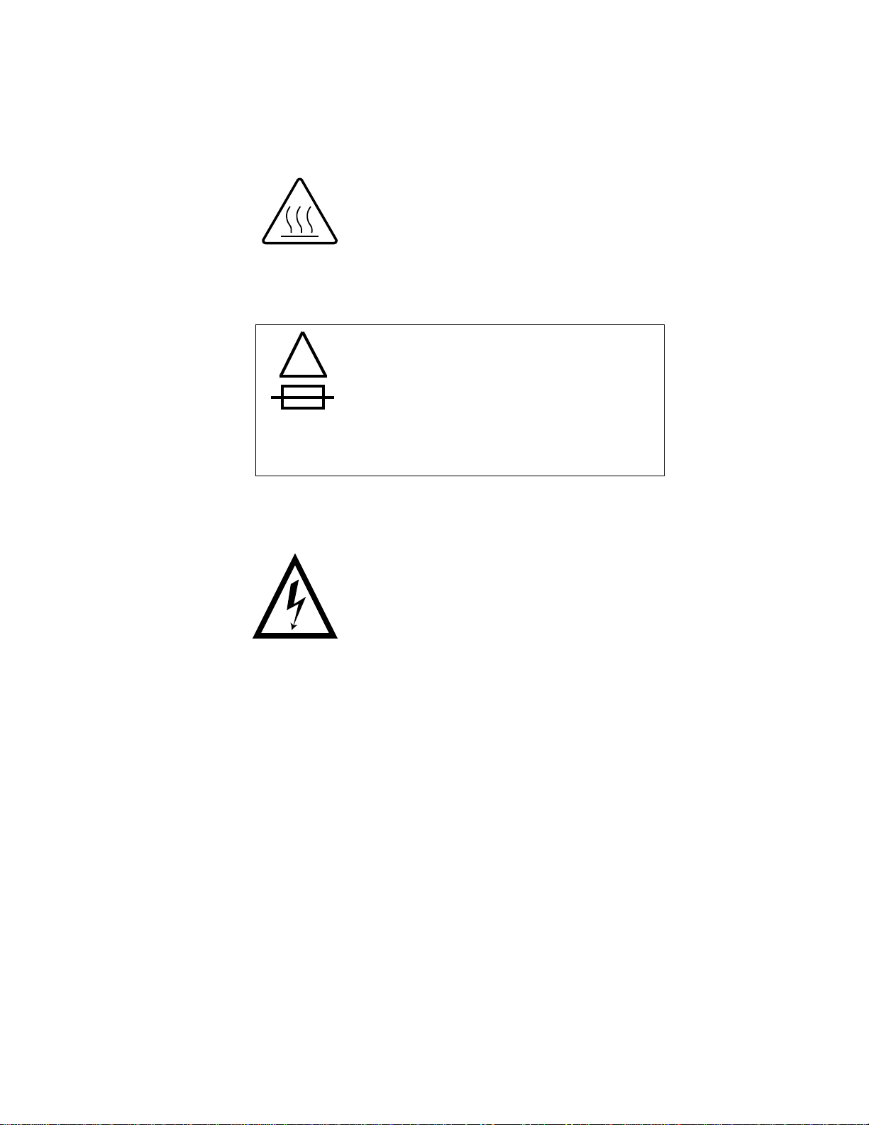
Cautionary Symbols
Hot Surface Symbol
CAUTION: Risk of burn. Wait at least 5 minutes for the surface to cool.
Fuse Label
!
CAUTION: Double pole / neutral fusing.
ATTENTION: Double pôle / fusible sur le neutre.
ACHTUNG: Zweipolige bzw. Neutralleiter - Sicherung!
CAUTION: The scanner uses double pole/neutral fusing.
(2) 100-120 V 50/60 Hz 6.3 A / 250 V / F
(2) 200-240 V 50/60 Hz 3.15 A / 250 V / T
Electrical Hazard Symbol
French:
Symbole de Danger Électrique
German:
Elektrisches Gefahrensymbol
CAUTION: Risk of electrical shock. Test before touching.
French:
ATTENTION: Danger D’ Électrocution. Vérifier avant de toucher.
German:
VORSICHT: Gefahr von elektrischem Schlag. Vor Berührung prüfen.
vi May 2002
Page 7

Mechanical Hazard Symbol
French:
Symbole de Danger Mécanique
German:
Mechanisches Gefahrensymbol
CAUTION: Moving parts. Avoid contact.
French:
ATTENTION: Pièces en mouvement. Ne pas toucher.
German:
VORSICHT: Bewegliche Teile. Nicht berühren.
Regulatory Information
Warranty Information
The following warranty information pertains to equipment that is installed in the
United States only. For equipment installed in countries other than the United
States, the terms and conditions of the new equipment warranty are provided by
the Kodak company in the country in which the sale is finalized, or by a Kodakappointed distributor in those countries where Kodak does not have direct sales
representation.
Warranty Period
Kodak warrants new equipment to function properly for 90 days from the date of
initial installation. This warranty covers the purchaser of the equipment as well as
anyone else who owns it during the warranty period.
Warranty Repair Coverage
If this equipment does not function properly during the warranty period, a Service
and Support Field Engineer from Kodak will repair the equipment without charge
during Kodak’s normal working hours (usually 8:00 a.m. to 5:00 p.m., Monday
through Friday). Such repair service will include any adjustments and/or
replacement of parts required to maintain your equipment in good working order.
Supply items are billed as required.
How to Obtain Service
Before you call, please know your scanner’s K-Number. The K-Number label is
attached to the front of the scanner chassis near the filter and lamp; lift the lampand-filter-access door to see the K-number (see Front View on page 1-4).
For service and support:
• In the United States: call Eastman Kodak Company at 1-800-822-1414.
• Outside the United States: contact your local Kodak representative.
May 2002 vii
Page 8

Regulatory Information
Limitations
Warranty service is limited to areas within Kodak’s established marketing centers
in the contiguous United States, the island of Oahu in Hawaii, and some areas of
Alaska.
This warranty does not cover circumstances beyond Kodak’ s control; it does not
cover service or parts for any attachments, accessories, or alterations not
marketed by Kodak, nor to correct problems resulting from their use.
Damage caused by failure to meet the electrical specification in this manual is not
covered under the warranty to service agreement claim.
Kodak makes no other warranties, express, implied, or of merchantability,
for this equipment.
Repair or replacement without charge is Kodak’s only obligation under this
warranty. Kodak will not be responsible for any consequential or incidental
damages resulting from the sale, use, or improper functioning of this equipment,
even if loss or damage is caused by the negligence or the fault of Kodak.
Such damages, for which Kodak is not responsible, include, but are not limited to,
loss of revenue or profit, downtime costs, loss of use of the equipment, cost of any
substitute equipment, and facilities or services of claims of your customers for
such damages.
This limitation of liability does not apply to claims for injury to persons or damage
to property caused by the sole negligence or fault of Kodak or by persons under
its direction or control.
Kodak Service Agreements
For information on Kodak service agreements:
In the United States: call Kodak’s Service Marketing Contract Administration and
Billing Support at 1-800-645-6325.
Outside the United States: contact your local Kodak representative.
viii May 2002
Page 9

Contents
Regulatory Information....... ....... ...... ....... ...................................... ....... ...... ....... ...... ....... .........................v
Cautionary Symbols .... ....................................... ....... ...... ...... ....... ...... ............................................ vi
Warranty Information..................................................................................................................... vii
About This Guide ................................... ...... ....................................... ...... ....... ...... ....... ..... ................... xi
Using This Guide............................................................................................................................ xi
1 Introduction and Overview ..................................................................................................................1-1
Product Description ......................................................................................................................1-1
Features and Benefits ........................................ ....... ...... ...... ....... ...... .................................. ........1-2
Before You Begin .........................................................................................................................1-3
Equipment Overview ....................................................................................................................1-4
Recommended Configuration of the Host Computer....................................................................1-5
Film Sizes.....................................................................................................................................1-6
2 Connecting and Operating the Scanner..............................................................................................2-1
Preparing the Host Computer.......................................................................................................2-1
Connecting the Scanner ...............................................................................................................2-2
Starting Up the Scanner System ..................................................................................................2-6
Operating the Scanner .................................................................................................................2-8
Shutting Down the Scanner....................................... ...... ...... ....... ...... ........................................2-13
3 Validating the Scanner........................................................................................................................3-1
Starting the SAM Software ...........................................................................................................3-2
Setting the Magnification ..............................................................................................................3-4
Calibrating the Scanner ................................................................................................................3-5
Making a Test Scan......................................................................................................................3-6
Autofocusing.................................................................................................................................3-8
Scanning the Image......................................................................................................................3-9
Checking the Scan .......................................................................................................................3-9
4 Maintaining the Equipment..................................................................................................................4-1
Cleaning Procedures... ....... ...... ....... ...... ....... ...................................... ....... ...... ....... ...... ....... .........4-1
Replacement Procedures... ....................................... ...... ...... ....... ...... ....... ...................................4-2
May 2002 ix
Page 10

Contents
Appendix A: Using the Service and Assembly Module (SAM)............................................................... A-1
Installing the Service and Assembly Module (SAM) Software.....................................................A-2
Using Operations......................................................................................................................... A-3
Appendix B: Ordering Accessories and Supplies.................................................................................. B-1
Accessories ................................................................................................................................. B-1
Supplies....................................................................................................................................... B-2
Appendix C: Scanner Specifications......................................................................................................C-1
Appendix D: Using the Long Roll Accessory .........................................................................................D-1
Installing the Software for the Long Roll Accessory ..................... ...... ....... .................................. D-2
Installing or Removing the Long Roll Accessory .........................................................................D-5
Punch Sensors ..........................................................................................................................D-14
Setting the Punch Reader Height for the Current Film Size......................................................D-14
Appendix D-1: Calibrating the Sensor Offsets...........................................................................D-23
Appendix D-2: Determining and Setting the Trigger Points.......................................................D-31
Appendix D-3: Maintenance ......................................................................................................D-34
Appendix D-4: Initial Setup of Sensors......................................................................................D-38
Appendix D-5: Table of Scan Area Values ................................................................................ D-41
Appendix D-6: Film Splicing and Editing Guidelines .................................................................D-42
x May 2002
Page 11

This User’s Guide for the KODAK PROFESSIONAL HR 500 Plus Film Scanner
and the KODAK PROFESSIONAL HR Universal Scanner includes procedures for
operating, maintaining, and troubleshooting the scanner. It also includes an
appendix for the optional Long Roll Accessory.
This guide is intended for personnel who operate the scanner. It assumes you
have a basic knowledge of computer operations and film scanners.
Using This Guide
Chapter 1 Introduction—product description, features and benefits, equipment
Chapter 2 Connecting and Operating the Scanner—connecting the scanner to
Chapter 3 V alidating the Scanner—instructions for using the Service and
About This Guide
overview, and recommended configuration
the host computer, starting up the scanner, preparing to scan an image,
performing a scan and shutting down the scanner
Assembly Module (SAM) and Adobe PhotoShop software to validate that
the scanner functions properly
Chapter 4 Maintaining the Equipment—procedures to be done by the person in
your lab who is responsible for maintenance of the scanner
Appendix A Using the Service and Assembly Module (SAM)—an overview of
using SAM for validating the scanner and for other user functions
Appendix B Ordering Accessories and Supplies—includes descriptions and order
numbers for scanner accessories and supplies
Appendix C Scanner Specifications—includes space, electrical, and environmental
requirements for the scanner
Appendix D Using the Long Roll Accessory—instructions for installing and using
the (optional) Long Roll Accessory with the scanner
May 2002 xi
Page 12

About This Guide
xii May 2002
Page 13

1 Introduction and Overview
This chapter includes:
• product description
• features and benefits
• equipment overview
• recommended configuration for host computer
• film sizes
Product Description
With the Kodak Professional HR 500 Plus Film Scanner and the Kodak
Professional HR Universal Film Scanners, you can quickly generate high-
resolution digital images from photographic negatives and positives.
You can digitally capture images and store them in files up to 128 MB (format
dependent) in size. The scanner is capable of variable magnifications from
0.5to2.0.
The new DIGITAL ICE technology corrects blemishes and defects on negatives
and reduces your post-print retouching time.
With the HR 500 Plus Film Scanner, you can use films ranging from 35 mm to 70
mm widths, including 46 mm width film and the 120 series formats, with up to 90
mm frame lengths.
With the HR Universal Scanner, you can use all film formats, from 35 mm to 70
mm widths, including 46 mm width film, the 120 series formats, and 4 x 5 sheet
film, with up to 125 mm frame lengths.
How the Scanner Works
The image on the film is focused onto a Charged Coupled Device (CCD) that has
three parallel linear rows of light-sensitive elements, one row for each color. Each
of these lines is exposed to a corresponding line of image on the film. The time to
expose each line properly is controlled electronically and is a function of the:
• sensitivity of the CCD
• amount and spectral distribution of light from the light source
• lens aperture
• magnification factor
After the exposure, the data from the photosensitive sites on the CCD is
transferred to readout registers for each line, where it is then shifted out and
digitized one pixel at a time. While the data is shifted out, the next set of lines is
exposed.
The film is moved to expose a new line of the image for each set of lines read from
the CCD. This motion is precisely controlled to ensure that the aspect ratio of the
image is not changed and that the colors align correctly when the data is
recombined to correct for the distance between the sensor rows.
May 2002 1-1
Page 14

Introduction and Overview
Features and Benefits
Features and benefits of the HR 500 Plus and Universal Film Scanners include:
• high speed and high image quality digital capture
• handling of cut negatives, mounted slides, strips, short rolls, and long roll
lengths up to 200 feet (61 meters)
• compatibility with familiar software, such as
– Kodak Professional Digital Print Production Software (DP2)
– Kodak Professional HR 500 TWAIN Data Source, which can be used with
any TWAIN-compliant program
• compatibility with familiar hardware, such as Kodak Professional Digital
Multiprinters and Kodak Professional LED Printers
• the new DIGITAL ICE technology that corrects blemishes and defects on
negatives and reduces your post-print retouching time
• the ability to store calibrations, resulting in improved workflow
1-2 May 2002
Page 15

Before You Begin
It is important that you know when to calibrate and when to focus the scanner. The
table below is a guideline for calibrating and focusing. Focusing can occur as
infrequently as when a different film format is scanned or as frequently as every
scan.
Introduction and Overview
Action or Condition
Changing the magnification Yes* Yes
Replacing the lamp Yes No
Changing the balance filter position from negative
to positive or from positive to negative
The scanner has not been calibrated at least twice
during the first half of a production shift
Cleaning the light bar Yes No
Replacing the balance filters or the IR filter Yes No
Changing the film holder size without changing the
magnification
Scanning slides and aperture cards No Operator
Changing from scanning a long roll to scanning a
cut negative
Need to
Calibrate?
Yes Yes
Yes* No
Yes* Operator
Yes Yes
Need to
Focus?
Preference
Preference
* The need to calibrate partially depends on whether you are using stored
calibrations and the length of time the calibrations are stored (usually about 3
hours)
You can manipulate scanned images using a program such as the Kodak
Professional Digital Print Production Software (DP2) or the Kodak Professional
HR 500 TWAIN Data Source before sending the images to your digital printer.
May 2002 1-3
Page 16
Introduction and Overview
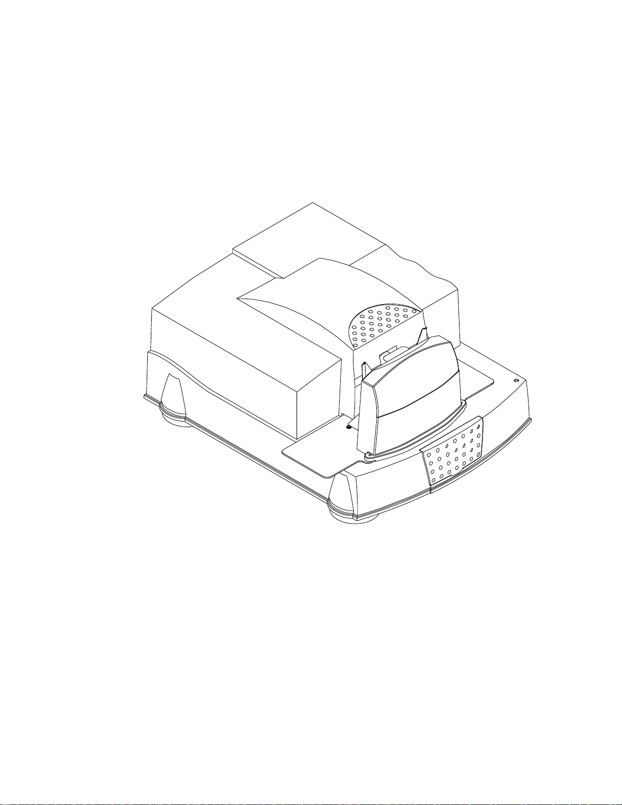
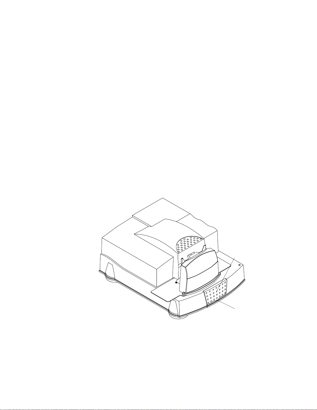
Equipment Overview
Front View
P192_0016HC
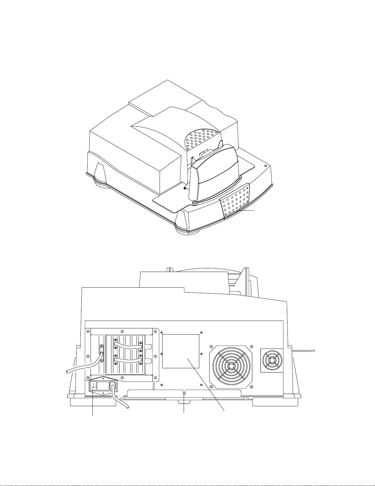
Rear View
Serial
Number XXX
K-number is
visible when this
door is open
power switch
P192_0019HC
1-4 May 2002
latch release
screw
dataplate includes
serial number
Page 17

Introduction and Overview
Recommended Configuration of the Host Computer
The scanner is only certified to communicate with Windows NT and Windows
2000 platforms with the following configuration.
IMPORTANT: To ensure proper operation of the scanner, use the Ultra-Wide
SCSI board provided with the scanner.
Built-in SCSI interfaces in some computers may interfere with the
provided Ultra-Wide SCSI board.
Host Computer Hardware Requirements
A SCSI cable connects the host computer to the scanner. This interface enables
the transfer of digital image data from the scanner to the host computer.
If you follow the recommended host computer hardware requirements, you can
expect higher performance.
IMPORTANT: The SCSI board must be dedicated to running only the HR Film
Scanner.
Minimum Recommended
Dual Pentium III/600 MHz Dual Pentium III or IV/1.2 GHz
512 MB memory 1 GB memory
10 GB available disk space 40 – 60 GB available disk space
CD-ROM drive
19- to 21-inch Color Monitor
24-bit Color Display Card with at least 16 MB video RAM
Dedicated SCSI host adapter (provided with scanner)
High-speed internet connection
Recommended Software Requirements
• Windows NT 4.0 or Windows 2000, Service Pack 6 or 6A for using the
scanner and software
• Microsoft Internet Explorer 5.01 or higher
• Adobe Photoshop 5.5 or higher for validating operation of the scanner
May 2002 1-5
Page 18

Introduction and Overview
Film Sizes
Commonly available color negative, color reversal (positive), and black-and-white
films are supported by the scanner.
Both the HR 500 Plus Film Scanner and the HR Universal Scanner accept these
film sizes:
• 35 mm
– standard perforated format
– un-perforated, up to 60 mm frame length
• 46 mm, up to 90 mm frame length
• 120/220 (62 mm)
– 6 x 4.5 cm
– 6 x 6 cm
– 6 x 7 cm
– 6 x 8 cm
– 6 x 9 cm
• 70 mm
– split 70 mm
– full 70 mm
Additionally, the HR Universal Scanner accepts 4 x 5-in. sheet film.
Film Holders Provided with the Scanner
Cut-gate film holders for these film sizes are provided with the scanner:
• 35 mm double-perforated
• 35 mm mounted slides
• 70 mm-CAL with the HR 500 Plus Film Scanner
• 4 x 5 with the HR Universal Film Scanner
• 6 x 4.5 cm vertical
• 6 x 4.5 cm horizontal
• 6 x 6 cm
• 6 x 7 cm
• 6 x 9 cm
1-6 May 2002
Page 19

2 Connecting and Operating the Scanner
This chapte r gives instructions for:
• preparing the host computer
• connecting the HR Film Scanner to the host computer
• starting up the scanner system
• preparing to scan an image
• performing a scan
• shutting down the scanner
Preparing the Host Computer
CAUTION: Do not connect power to the scanner.
1. Install the Ultra-Wide SCSI board into the host computer.
IMPORTANT: Check the README file on the CD before you install the
software.
2. Install the SAM software. See Installing the Service and Assembly Module
(SAM) Software on page A-2.
May 2002 2-1
Page 20
Connecting and Operating the Scanner
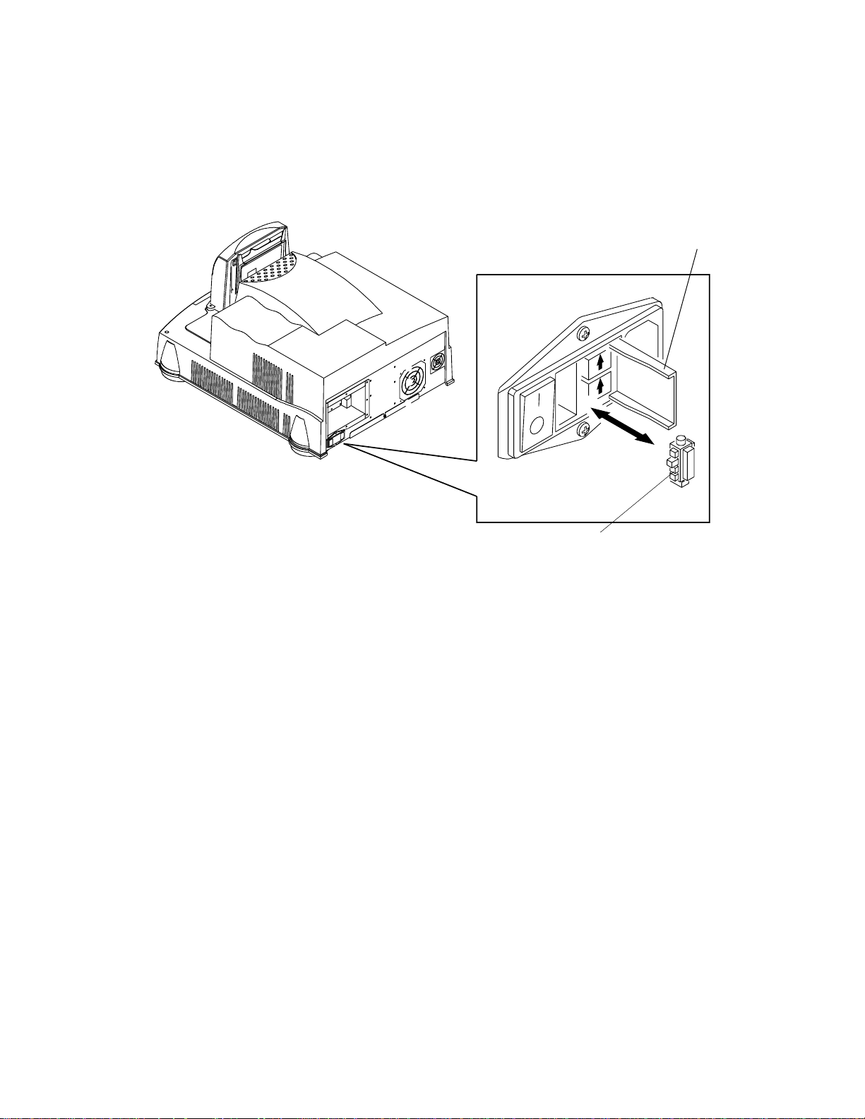
Connecting the Scanner
CAUTION: Make sure the setting on the AC input module on the bac k of the
scanner agrees with the power source.
AC input module
P192_0019HC
The AC input module is factory-set to 115 V AC (60 Hz) as labeled. The
accessories shipped with your scanner include two 220 V fuses (3.15 amps) to
convert the scanner to 220 V operation.
If your power source is 220 or 230 V AC, verify the configuration of the AC input
module. In some regions, the setting and the fuses may have been changed for
you. If not, follow the procedure for Changing the AC Input V oltage Setting and the
Fuses.
Remove the voltage sticker from the AC input module.
2-2 May 2002
Page 21
Connecting and Operating the Scanner
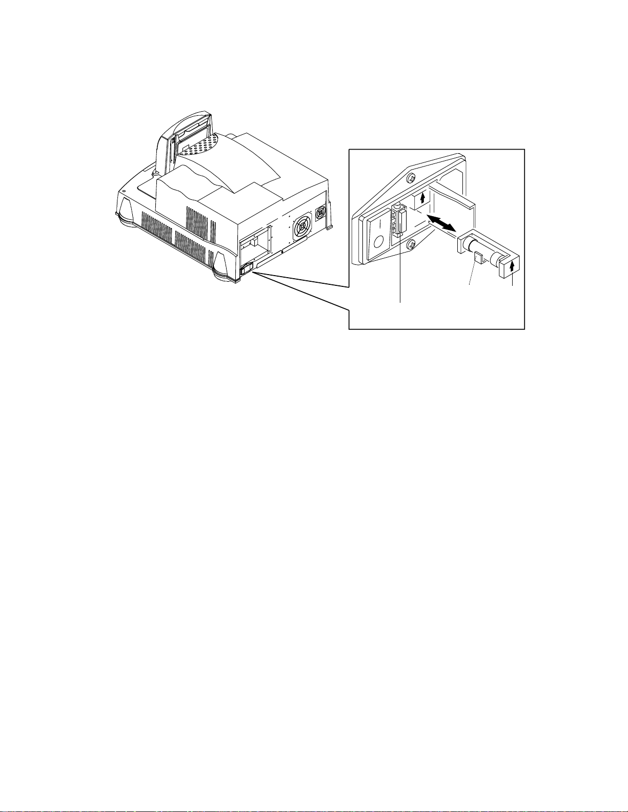
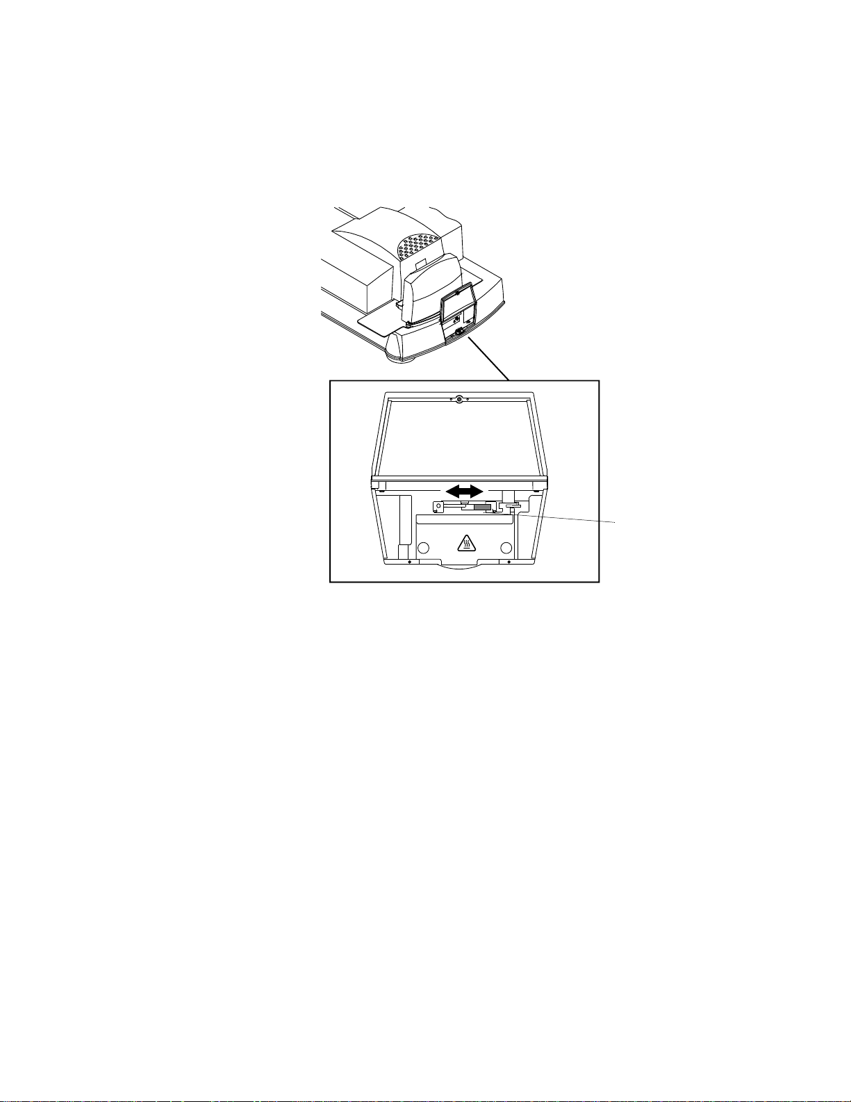
Changing the AC Input Voltage Setting and the Fuses
If needed, change the AC input voltage setting (voltage selector switch) and both
fuses from 115 V AC to 220 V AC operation:
1. Make sure the power cord is removed from the scanner.
locking tab
115 V
voltage selector switch
2. Insert a straight-blade screwdriver into the locking tab to open the AC input
module.
3. Using your fingers (or, if needed, needle-nose pliers), remove the voltage
selector switch.
4. Orient the voltage selector switch with 220 V AC facing you and insert it into
the AC input module.
May 2002 2-3
Page 22
Connecting and Operating the Scanner
5. Remove the two 115 V AC (6.3 amp) fuses and replace them with the
220 V AC (3.15 amp) fuses. Make sure the arrows are pointing up.
115 V
6. Close the AC input module.
fuse in holder
fuse
arrow
2-4 May 2002
Page 23

SCSI
cable
Connecting and Operating the Scanner
Attachin g t h e Cables
CAUTION: In the next step, av oid f orcing the cable pins when plugging the
cable into the scanner. You need a straight-blade screwdriver to
complete the attachment of the cable to the scanner.
1. Attach the Ultra-Wide SCSI cable to the scanner and to the host computer.
The host end of the cable contains ferrite beads.
2. Attach the power cable from the scanner to the power source.
ferrite beads
power cable
P192_0100HC
May 2002 2-5
Page 24
Connecting and Operating the Scanner
Starting Up the Scanner System
NOTE: If the scanner’s power has been on and the scanner has been calibrated,
continue with Operating the Scanner beginning on page 2-8.
IMPORTANT: Before operating the scanner in a production environment for the
first time, validate that the scanner is working properly. See
Chapter 3, Validating the Scanner.
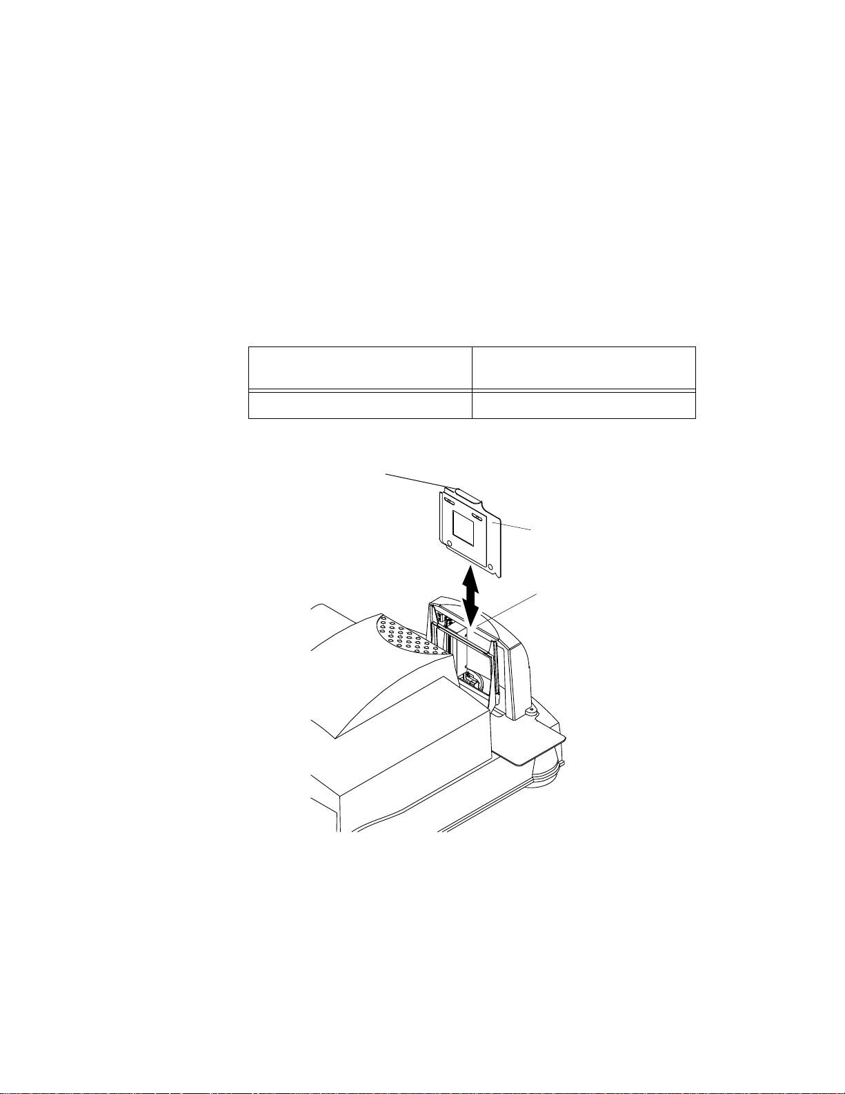
Placing the Empty Film Holder in the Film Holder Guide
The empty film holder must be in place in the film holder guide when you power up
the scanner.
Film Holder for
HR 500 Plus Film Scanner
70MM-CAL 4 x 5
edge of handle facing back
of scanner
Film Holder for
HR Universal Film Scanner
L
A
C
-
M
M
0
7
70MM-CAL film holder
film holder guide
P192_0020GC
1. With the edge of the top handle facing the back of the scanner, center the film
holder between the two rails of the film holder guide.
2. Lower the film holder and let it gently fall into place in the scanner.
3. With your finger, apply pressure to the handle to make sure the film holder is
fully seated.
2-6 May 2002
Page 25
Connecting and Operating the Scanner
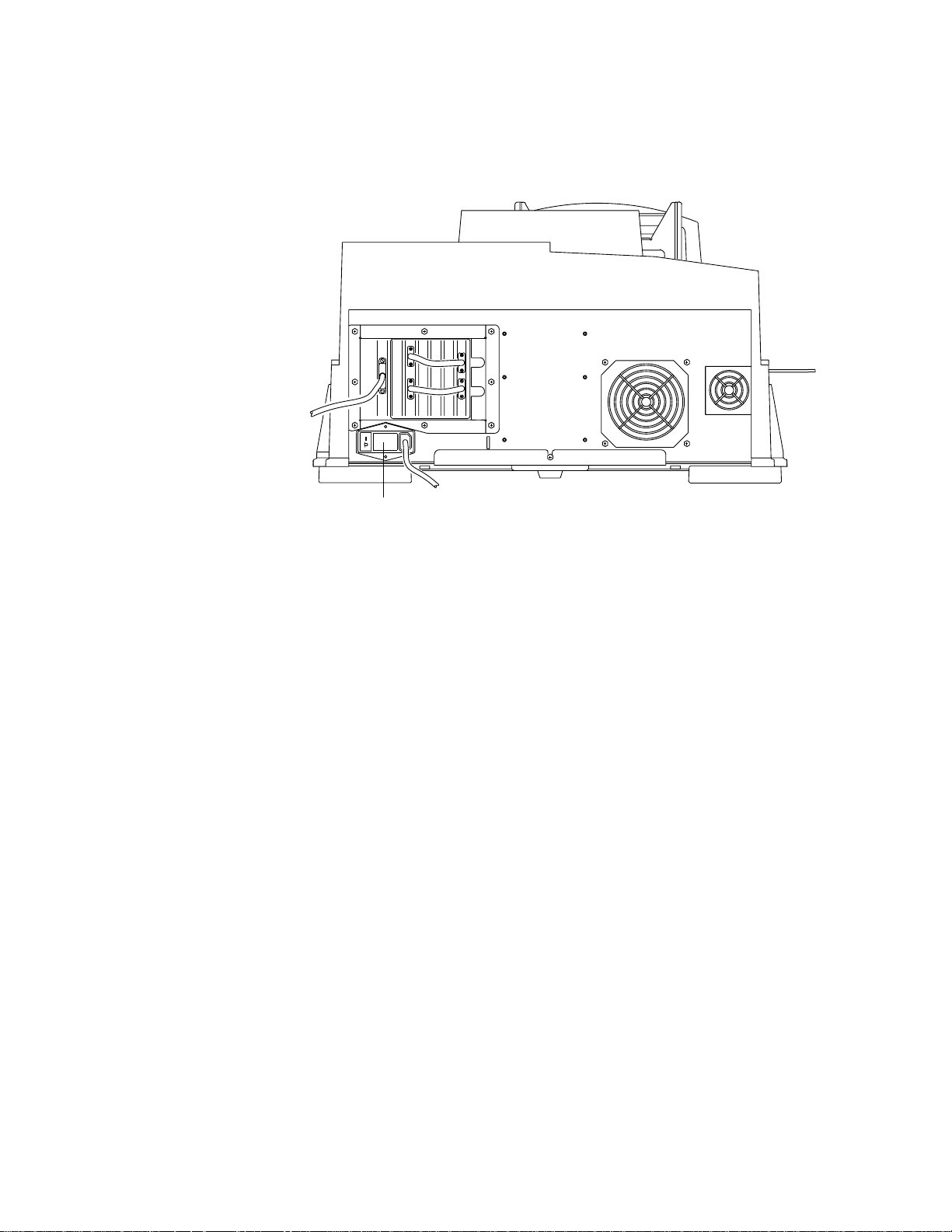
Powering up the Scanner and the Host Computer
1. Turn on the scanner’s power switch.
NOTE: The green LED light on the scanner indicates only that AC power is
supplied to the scanner, not that the system is ready.
Three sets of beeps will sound (first set: one beep; second set: two short
beeps; third set: two short, then one lon g beep) .
As a visual indicator that the scanner is ready, the scanner lamp lights and
remains lit.
2. Turn on power to the host computer and wait until the computer desktop
appears.
3. Wait 10 minutes for the lamp to warm up.
power switch
P192_0019HC
May 2002 2-7
Page 26
Connecting and Operating the Scanner
Operating the Scanner
Setting the Magnification and Calibrating the Scanner
Use your host computer’s scanner software to do this procedure.
NOTE: The terminology used in your scanner software may differ from that used
in this document. Refer to the software manual’s instructions for performing
specific operations such as calibrating the scanner and setting the
magnification.
With the empty film holder (70MM-CAL for HR 500 Plus and 4 x 5 for
HR Universal) in place in the scanner:
1. Set the magnification to the desired level.
2. Calibrate the scanner.
Setting the Scan Parameters
Using the software installed on your host computer, set the scan parameters, such
as the area to be scanned and the file that will contain the scanned image.
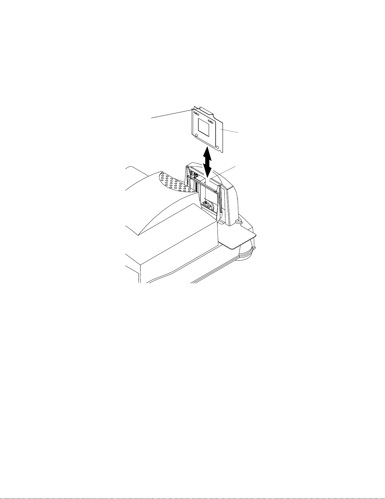
Selecting the Negative or Positive Balancing Filter
lamp-and-filteraccess door
P192_0016HC
1. Lift open the lamp-and-filter-access door.
lift door open from
here
2-8 May 2002
Page 27
Connecting and Operating the Scanner
2. Make sure the red handle is in the correct position—either negative or
positive—for scanning a negative or a mounted slide (positive).
IMPORTANT: If you changed the setting of the balance filter, you must
calibrate the scanner before continuing. See Setting the
Magnification and Calibrating the Scanner on page 2-8.
POS NEG
red handle is in
NEG position
May 2002 2-9
Page 28

Connecting and Operating the Scanner
Placing a Negative or Mounted Slide in the Film Holder
Select the appropriate film holder for the negative or mounted slide you will be
scanning.
Preparing a Carded Negative
IMPORTANT: For best focus, use the film holder that is closest to the size of the
1. Lift the film holder’s magnetic sheet.
IMPORTANT: In the next step, the emulsion side must be toward the rear of the
2. With the emulsion side toward the rear of the scanner, locate the carded
negative on the film holder’s two pins.
3. Carefully close the magnetic sheet over the carded negative.
carded
negative
opening in the aperture card.
scanner.
emulsion
side
magnetic
sheet
pin
film holder
P192_0021AC
Continue with Placing the Film Holder in the Scanner on page 2-12.
2-10 May 2002
Page 29

Connecting and Operating the Scanner
Preparing an Uncarded Negative
Wear clean, cotton gloves when handling the negative. Illuminate the negative
with a light box or hold the negative up to the light to view and align the negative.
1. Identify the emulsion side of the negative.
The emulsion side is the dull side of the negative. The printing appears
backwards.
2. Select either landscape or portrait orientation.
3. Lift the magnetic sheet.
IMPORTANT: In the next step, the emulsion side must be toward the rear of the
scanner.
4. With the emulsion side toward the rear of the scanner, carefully align the
negative over the rectangular opening in the film holder.
5. Close the magnetic sheet over the negative.
Continue with Placing the Film Holder in the Scanner on page 2-12.
Preparing a Mounted Slide
IMPORTANT: In the next step, the emulsion side must be toward the rear of the
scanner.
1. With the emulsion side toward the rear of the scanner, align the mounted slide
on the film holder between the pins.
2. Carefully insert the mounted slide under the film holder’s clamps and into
place, keeping the slide aligned.
May 2002 2-11
Page 30
Connecting and Operating the Scanner
Placing the Film Holder in the Scanner
1. Hold the film holder guide so the top handle faces the back of the scanner.
Center the film holder between the two rails of the film holder guide.
2. Lower the film holder and let it gently fall into place in the scanner.
3. With your finger, apply pressure to the handle to make sure the film holder is
fully seated.
edge of handle facing back
of scanner
film holder
film holder guide
P192_0020GC
2-12 May 2002
Page 31

Focusing
With the negative or mounted slide installed in the scanner, use the software
installed on your host computer to focus the scanner.
IMPORTANT: The need for focusing is partially dependent on the “depth of field.”
When the magnification is lower—for example, 0.5—the depth of
field is greater and the focus tolerance is high. As the magnification
increases, the depth of field and the focus tolerance decrease.
Therefore, it may be necessary to focus more frequently for higher
magnifications.
Scanning a Single Frame
Using the software installed on your host computer, scan the negative or mounted
slide.
Shutting Down the Scanner
Follow this procedure when you do not plan to use the scanner for extended
periods of time, such as over the weekend.
Connecting and Operating the Scanner
1. Close the host software program.
2. Turn off power to the scanner.
May 2002 2-13
Page 32

Connecting and Operating the Scanner
2-14 May 2002
Page 33

3 Validating the Scanner
This chapter includes instructions for using the Service and Assembly Module
(SAM) and Adobe Photoshop software to validate that the scanner functions
properly.
NOTES: For more information about using the Service and Assembly module
software on the host computer, see Appendix A.
Before scanning for the first time, set up a folder (on your host
computer) for your work. Especially if you have more than one scanner,
include the scanner serial number (on the dataplate on the back of the
scanner) in the folder name.
IMPORTANT: The empty CAL film holder (70MM-CAL for HR 500 Plus Film
Scanners and 4 x 5 for HR Universal Film Scanners) must be in
position in the scanner before you start SAM. See Placing the
Empty Film Holder in the Film Holder Guide on page 2-6.
May 2002 3-1
Page 34

Validating the Scanner
Starting the SAM Software
1. Open SAM. The Operations window appears with the Mag/Focus tab
displayed.
3-2 May 2002
Page 35

2. Perform a backup of the scanner files:
a. Click the Backup & Restore tab.
b. Click Backup.
Validating the Scanner
May 2002 3-3
Page 36

Validating the Scanner
Setting the Magnification
1. Click the Mag/Focus tab.
2. Select a Chosen Magnification of 1.00.
3. Click Do Magnification.
The lens moves into position.
A message appears stating that there is no stored calibration.
3-4 May 2002
Page 37

Calibrating the Scanner
1. Click the Calibrate/Image Processing tab.
Validating the Scanner
2. For the purposes of validating the scanner, make sure the values on the
Calibrate/Image Processing tab match the values shown on the sample. The
sample is a representation of the default values.
3. Select Shift Image Data Bits Up by Four.
4. Click Calibrate All.
May 2002 3-5
Page 38

Validating the Scanner
Making a Test Scan
Before you scan an image, you must identify the area to be scanned and the file
that will contain the scanned image.
1. Click the Capture tab.
2. Enter the file information:
a. Select Save image to file.
b. Click Browse.
c. Navigate to the folder for storing your images.
d. Click Open to enter the Path.
3-6 May 2002
Page 39

Validating the Scanner
3. Use the table below only as a starting point for determining Scan Area
values.
NOTE: Keep the Line Offset (y): at the default value of 0 and keep Pixel
Summing at the default value of None.
IMPORTANT: The Pixel Offset must be greater than or equal to the first
calibrated pixel and # Pixels must be less than or equal to the
last calibrated pixel minus the first calibrated pixel.
Cut-Gate Film
Holders
35 mm doubleperforated
46 mm 0.50 1754 2123 2554 12.8
6 x 4.5 cm
vertical
6 x 4.5 cm
horizontal
6 x 6 cm 0.50 2368 1816 2250 15.2
6 x 7 cm 0.50 2368 1816 2775 18.8
Magnification # Pixels Pixel Offset # Lines
0.50 1033 2484 1460 4.3
1.03 2129 1936 3008 18.3
2.00 4133 934 5840 69.1
0.60 2105 1948 3065 18.5
1.58 5542 229 8071 128.0
0.50 2368 1816 1539 10.4
0.66 3126 1437 2031 18.2
1.26 5967 17 3878 66.2
0.50 1539 2231 2368 10.4
0.66 2031 1985 3126 18.2
1.26 3878 1061 5967 66.2
0.55 2605 1698 2475 18.5
1.26 5967 17 5670 96.8
File Size
(MB)
1.26 5967 17 6994 119.4
6 x 9 cm 0.50 2368 1816 3325 22.5
1.19 5636 182 7914 127.6
Split 70 mm 0.50 2483 1759 1632 11.6
0.63 3129 1436 2056 18.4
1.20 5960 20 3917 66.8
70 mm 0.50 2682 1659 3450 26.5
1.09 5846 77 7522 125.8
4 x 5 in. 0.50 3972 1014 5026 57.1
0.74 5878 61 7439 125.1
max mag 2.00 6000 0 7333 125.9
min mag 0.50 2917 1542 3750 31.3
May 2002 3-7
Page 40

Validating the Scanner
Autofocusing
1. Install a negative or mounted slide in the scanner. (See Selecting the
Negative or Positive Balancing Filter on page 2-8.)
2. Click the Mag/Focus tab.
3. Click Do AutoFocus.
3-8 May 2002
Page 41

Scanning the Image
1. Click the Capture tab.
2. Click Scan.
Checking the Scan
Validating the Scanner
1. On the Capture tab, click Ope n Im ag e.
Adobe Photoshop opens.
2. In Photoshop, enter the required values.
a. Enter the Dimensions:
• Width = Actual #Pixels when Pixel Summing is None.
• Height = Actual #Lines when Pixel Summing is None.
May 2002 3-9
Page 42

Validating the Scanner
b. Enter the Channel information:
• Set the Count to 3.
• Make sure Interleaved is selected.
• Set Depth to 16 Bits.
• Set Byte Order to IBM PC.
3. Click OK.
After a few seconds, the raw image appears.
4. Select Image>Adjust>Auto Levels.
After a few seconds, a clearer image should appear.
5. Select Image>Rotate Canvas>Flip Vertical.
NOTE: You may also need to select Image>Rotate C anvas>90° CCW.
6. Check that the image appears as you expected.
7. If the image does not appear as you expected, repeat this procedure, making
sure you follow the instructions exactly. Then if you still do not get the
expected results, contact your Kodak representative.
3-10 May 2002
Page 43

4 Maintaining the Equipment
This chapter contains procedures to be done by the person who is responsible for
maintenance of the HR Film Scanners.
Items required for maintenance are:
• Kodak camel’s-hair brush (provided)
• dry, untreated microfiber cleaning cloth
• lint-free cloth
• white cotton gloves
• Phillips-head screwdriver
Cleaning Procedur es
To minimize the need for cleaning the scanner and to reduce the possibility of
artifacts, make sure your scanner is in a clean, low-traffic area that does not
collect much dust. Wood, tile, linoleum, or sealed concrete floors are preferable to
carpet.
Clean the surface of the scanner with a damp lint-free cloth as needed.
IMPORTANT: Please read the following before performing any cleaning
procedures.
Avoid using pressurized air or canned air near the scanner.
If it is necessary to use canned air to clean film, direct the air
stream away from the scanner.
Instructions for cleaning the balance and IR filters are included under
Replacement Procedures beginning on page 4-2.
IMPORTANT: The balance and IR filters are made of glass and are expensive to
replace. They are not included in the product warranty or service
contract. Use care when handling the balance and IR filters.
When you remove the filters, inspect them. Cleaning may be all that is required.
Otherwise, replace the filters as needed.
Cleaning the Lens
IMPORTANT: Wear white cotton gloves for this procedure to prevent oils and dirt
from being absorbed into the microfiber cleaning cloth.
1. Use the software installed on your host computer to set the magnification to
2.00, which positions the lens as near to the front of the scanner as possible.
2. Clean the front of the lens with the supplied camel’s-hair brush.
3. Check that the lens is clean; if not, clean with a dry, untreated microfiber
cleaning cloth.
May 2002 4-1
Page 44

Maintaining the Equipment
Cleaning the Light Bar
If artifacts appear on your scanned images, clean the light bar.
IMPORTANT: Wear white cotton gloves for this procedure to prevent oils and dirt
from being absorbed into the microfiber cleaning cloth.
1. Fold a dry, untreated microfiber cleaning cloth so the edge of the cloth is
about the thickness of the light bar.
NOTE: You can use an e-wipe, manufactured by Photographic Solutions, Inc.,
instead of a microfiber cleaning cl oth .
2. Gently move the edge of the microfiber cloth or e-wipe down the length of the
light bar one time.
3. Calibrate the scanner.
4. If an artifact remains after cleaning the light bar, check the light bar with a
magnifying glass for damage, such as a scratch or a chip. If there is damage
to the light bar, contact your Kodak representative for service.
Replacement Procedures
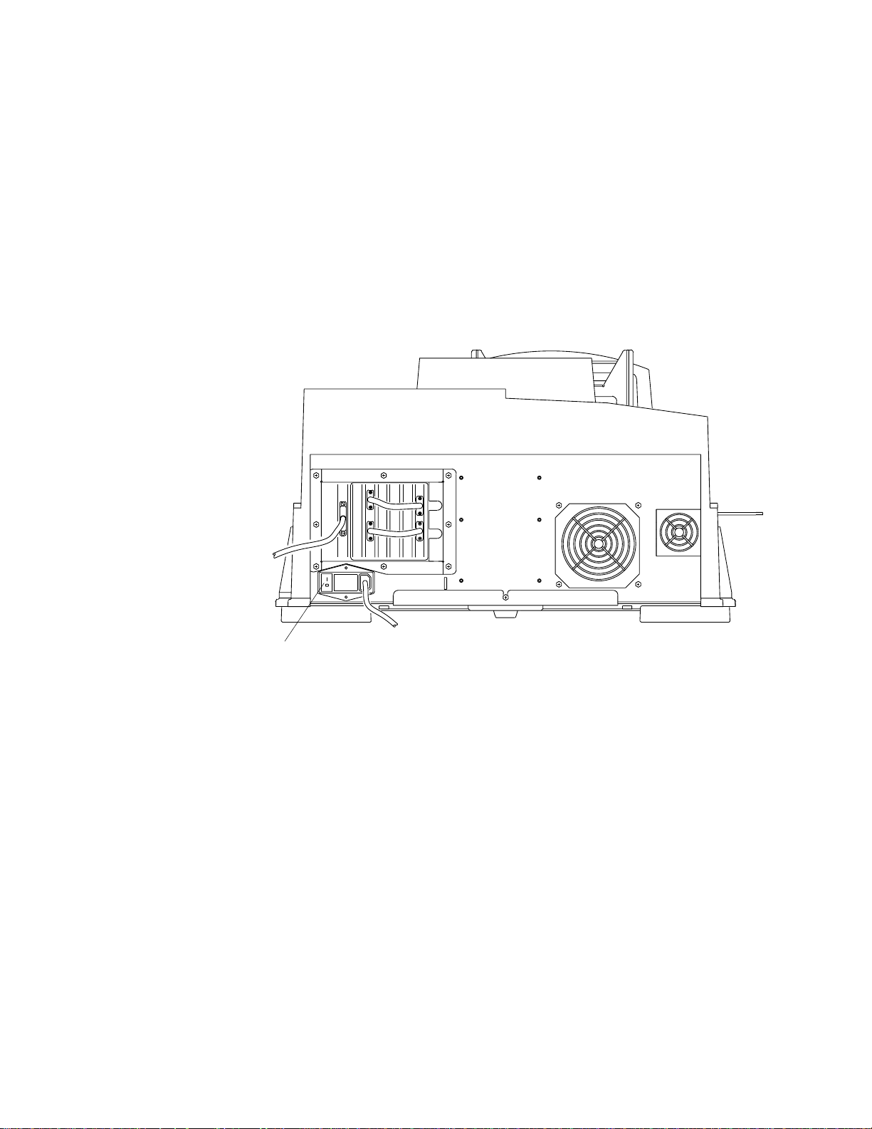
Replacing the Lamp
White cotton gloves are required for this procedure.
One spare lamp is provided with the scanner.
IMPORTANT: Use only the GE ELC Lamp with the HR Film Scanner (see
Appendix B: Ordering Accessories and Supplies).
It is not necessary to power down the scanner before changing the lamp.
lamp-and-filteraccess door
lift door open from here
P192_0016HC
1. Open the lamp-and-filter-access door.
4-2 May 2002
Page 45

lamp
Maintaining the Equipment
Hot Surface
symbol
leads
P192_0023GC
socket
thumbscrews
lamp cover
2. Loosen the thumbscrews on the lamp cover and pull the cover straight out.
When you remove the cover, the safety s witch is released, removing power to
the lamp socket.
CAUTION: Wait at least five minutes for the lamp to cool.
3. Push down the lamp release lever.
4. Remove the old lamp from the lamp socket.
5. Fully seat the new lamp in the socket; polarity is not important.
CAUTION: In the next step, to ensure correct alignment with the light bar,
it is extremely important to push the lamp to the back of the
lamp holder with the leads facing to the left. Improper
alignment affects the operation of the scanner.
6. With the socket leads facing left, reinstall the lamp in the lamp holder.
7. Reinstall the lamp cover and tighten the thumbscrews.
Power is reapplied to the lamp socket and the lamp should light.
8. Calibrate the scanner (see Calibrating the Scanner on page 3-5).
May 2002 4-3
Page 46

Maintaining the Equipment
Replacing the (Round) Balance Filters
IMPORTANT: The balance filters are made of glass and are expensive to replace.
It is not necessary to power down the scanner before changing the balance filters.
They are not included in the product warranty or service contract.
Use care when handling the balance filters.
Wear white cotton gloves for this procedure.
1. Open the lamp-and-filter-access door (see page 4-2 for the location of the
lamp-and-filter-access door).
NEG
POS
3 screws
balance-filter
assembly
red balance-filter assem bl y handle
2. Loosen the thumbscrews on the lamp cover and pull the cover straight out.
When you remove the cover, the safety s witch is released, removing power to
the lamp socket.
CAUTION: Wait at least five minutes for the lamp to cool.
3. Position the red balance-filter selection handle of the balance-filter assembly
in the center.
CAUTION: Use care with the IR filter. It is not secured in place. (For more
information about the IR filter, see Replacing the (Square) IR
Filter on page 4-5.)
4. Hold the red handle and pull the assembly straight out from the scanner.
5. Clean the filters with the camel’s-hair brush or, if needed, replace the filter(s)
as described in the next step.
4-4 May 2002
Page 47

Maintaining the Equipment
6. Replace the balance filters:
a. Remove the 3 screws.
b. Remove the filter retainer.
c. Remove the old filters and place the new filters in the filter holder.
The filters are coated on both sides. It is not important which side faces up
or down.
d. Secure the filters with the retainer and the 3 screws.
7. Install the filter assembly in the scanner with the balance-filter selection
handle in the middle.
8. Reinstall the lamp cover, tighten the thumbscrews, and select a filter position.
9. Calibrate the scanner (see Calibrating the Scanner on page 3-5).
Replacing the (Square) IR Filter
IMPORTANT: The IR filter is made of glass and is expensive to replace. It is not
included in the product warranty or service contract. Use care
when handling the IR filter.
Wear white cotton gloves for this procedure.
It is not necessary to power down the scanner before changing the IR filter.
1. Open the lamp-and-filter-access door (see page 4-4 for the location of the
lamp-and-filter-access door).
NEG
POS
IR filter (under balancefilter assembly)
red handle
2. Loosen the thumbscrews on the lamp cover and pull the cover straight out.
When you remove the cover, the safety s witch is released, removing power to
the lamp socket.
May 2002 4-5
Page 48

Maintaining the Equipment
10. Calibrate the scanner (see Calibrating the Scanner on page 3-5).
CAUTION: Wait at least five minutes for the lamp to cool.
3. Position the red balance-filter selection handle of the balance-filter assembly
in the center.
4. Hold the red handle and pull the assembly straight out from the scanner.
5. Push the IR filter up from below the filter assembly.
6. Clean t he I R fil ter with the came l’s-hair brush or, if needed, replace the IR filter
as described in step 7.
CAUTION: Use care with the IR filter. It is not secured in place.
7. If replacing the IR filter, set the new filter in place with the arrows on the edges
of the filter pointing down toward the scan lamp.
8. Install the filter assembly in the scanner with the balance-filter selection
handle in the middle.
9. Reinstall the lamp cover, tighten the thumbscrews, and select a filter position.
4-6 May 2002
Page 49

Appendix A: Using the Service and
Assembly Module (SAM)
The Service and Assembly Module (SAM) software performs many of the same
functions as other host software. Its primary purpose for users is to validate that
your scanner is working correctly and to allow you to perform simple scan
functions. There are also service and diagnostics functions that should be used
only with the assistance of a Kodak service representative.
Functions supported by the SAM software are:
• setting a magnification
• calibrating the scanner
• setting the image processing mode (negative or positive)
• autofocusing at any given magnification
• defining the area to be scanned
• scanning and transferring images from the scanner to the host computer
• performing miscellaneous features such as:
– turning the lamp on and off
– resetting the lamp-on timer
– rebooting the scanner
– retrieving scanner usage information
– displaying software version information
• backing up and restoring critical scanner files
A-1
Page 50

Using the Service and Assembly Module (SAM)
Installing the Service and Assembly Module (SAM) Software
1. Load the SAM CD.
2. Run setup.exe from the SAM CD.
3. Respond to the prompts in the installation program.
You must provide the program location and the name of the program menu
item.
4. When installation is complete, reboot your host computer.
5. Remove the CD and store it in a safe place.
Backing Up Scanner Files
IMPORTANT: It is essential that you back up the scanner files before using SAM.
1. Open SAM.
2. From the Operations window, click the Backup & Restore tab.
3. Click Backup to back up the critical scanner files.
A-2 May 2002
Page 51

Using Operations
If the Operations window does not appear, select View->Operations.
Using the Service and Assembly Module (SAM)
May 2002 A-3
Page 52

Using the Service and Assembly Module (SAM)
IMPORTANT: The Diagnostics, Sensors, Motors & Solenoids, and Transfer
tabs are not needed for user functions. Use these tabs only at
the request of your Kodak support representative.
A-4 May 2002
Page 53

Using the Service and Assembly Module (SAM)
Performing the Functions on the Mag/Focus Tab
IMPORTANT: Magnification Calibration should be done only with the guidance of
a Kodak support representative.
From the Operations window, click the Mag/Focus tab when you need to set the
magnification (position of the lens) or do an autofocus.
Setting the Magnification
1. On the Mag/Focus tab, select the Chosen Magnification. The value can be
between 0.5 and 2.0.
The scanner’s software maintains an internal Mag/Focus position table that
associates a motor position for each of the possible magnification values.
2. Click Do Magnification.
The lens and CCD move to the chosen position.
May 2002 A-5
Page 54

Using the Service and Assembly Module (SAM)
Performing an Autofocus
1. On the Mag/Focus tab, enter the Focus Range. The recommended value is
300. The Range is the initial range of travel used for the CCD and lens, in
motor steps.
NOTE:To make the focus procedure faster: if you have focused on a given
magnification, you can set the Range value to be less than 300.
IMPORTANT: Autofocus will be done for the Chosen Magnification. It is
assumed that when you do an Autofocus, you have:
• calibrated with an empty film holder (see Calibrating the
Scanner on page A-8)
• placed the film to be scanned in the scanner (see Placing
the Film Holder in the Scanner on page 2-12)
• set the scan area (see “Using the Capture Tab” on
page A-8); for fastest scanning, set the # of pixels (in the
Scan area) to 1000
2. Click Do AutoFocus.
A-6 May 2002
Page 55

Using the Service and Assembly Module (SAM)
Performing the Functions on the Calibrate/Image Processing Tab
From the Operations window, click the Calibrate/Image Processing tab when you
need to calibrate the scanner.
Setting Image Processing Parameters
1. Select the Data Path.
2. Select the LUT Selected.
3. Select the Dmin Settings.
4. Select the Colors Selected.
5. Select:
• Enable Dark and Gain Corrections
• Enable Defective Pixel Conceal
• Shift Image Data Bits Up by Four
May 2002 A-7
Page 56

Using the Service and Assembly Module (SAM)
Calibrating the Scanner
IMPORTANT: The CAL (70MM-CAL for HR 500 Plus Film Scanner and 4 x 5 for
HR Universal Film Scanner) film holder must be in position in the
scanner before you continue. See Placing the Empty Film Holder in
the Film Holder Guide on page 2-6.
1. If the values on the Calibrate/Image Processing tab do not match the values
shown on the sample on page A-7, change them. The sample is a
representation of the default values.
2. Select Shift Image Data Bits Up by Four.
3. Click Calibrate All.
Using the Capture Tab
From the Operations window, click the Capture tab when you need to perform a
scan.
A-8 May 2002
Page 57

Using the Service and Assembly Module (SAM)
Setting the Scan Area
To set the Scan Area, enter values for:
• # Pixels (valid values range from 1 through 6002); for fastest scanning, enter
a value of 1000
• Pixel Offset (valid values range from 0 through 6001)
• # Lines (valid values range from 1 through 7464)
• Line Offset (valid values range from 0 through 7463)
• Pixel Summing (valid values are None, 1:2, and 1:4)
NOTE:If you select Pixel Summing of 1:2 or 1:4, use the Actual #Pixels and
Actual #Lines for viewing the image in the Adobe Photoshop program.
Scanning the Image Data
1. If desired, save the scanned image as a file:
a. Enter the Path information (file destination).
b. Select Save image to file.
2. Click Scan.
May 2002 A-9
Page 58

Using the Service and Assembly Module (SAM)
Using the Miscellaneous Tab
Clicking the Miscellaneous tab on the Operations window lets you:
• turn the lamp on and off
• reset the lamp timer to zero
• reboot the scanner
• initialize the scanner
• set the scanner clock
• get scanner usage information
• get scanner attributes
• get version information
Click the appropriate button to perform the corresponding function.
A-10 May 2002
Page 59

Using the Service and Assembly Module (SAM)
Backing Up and Restoring Files
From the Operations window, click the Backup & Restore tab when you need to
perform either a backup or restore of the scanner files.
• Click Backup to back up scanner files.
CAUTION: Use Restore only when recommended by a Kodak support
person.
• Click Restore to copy backed up files to the scanner.
May 2002 A-11
Page 60

Using the Service and Assembly Module (SAM)
A-12 May 2002
Page 61

Appendix B: Ordering Accessories and
Supplies
Accessories
Item Description Order Number
Manual:
Kodak Professional HR 500 Plus Film & HR Universal
Film Scanners User’s Guide
Kodak Professional HR 500 Scanner Long Roll
Accessory 158 5496
Kodak Professional HR 500 35mm Scanner Strip Gate
Accessory 843 0316
Kodak Professional HR 500 Scanner 120 Strip Gate
Accessory 844 0554
Kodak Professional HR 500/Universal Scanner 35 x 45.2
Film Gate 892 3880
6B7198
Kodak Professional HR 500 Film Holders 890 7776
Kodak Professional HR 500 Carded Negative Film Gates
A-Crop
B-Crop
C-Crop
D-Crop
E-Crop
F-Crop
G-Crop
H-Crop
A-Square
B-Square
C-Square
D-Square
E-Square
141 1099
May 2002 B-1
Page 62

Ordering Accessories and Supplies
Available Accessori es
Static Elimination Kit
Available from:
Holter Associates, Inc.
1170 Pittsford-Victor Road, Pittsford, NY 14534
Phone: (716) 381-7988; Fax: (716) 381-2351
115 V Kit – Static Elimination Kit 2RSM80-115
230 V Kit – Static Elimination Kit 2RSM80-230
Super Film Cleaner or an equivalent cleaner with ionized
air and particle transfer rollers (PT R)
Super Film Cleaner is available from:
Brooke International
P.O. Box 30 0
Hansville, WA 98340-0300
Phone: (360) 638-2591; Fax: (360) 630-1658
Item Description Order Number
Supplies
Polymag Film Strip Cleaner available from:
www.polymagtek.com
Phone: (800) 787-0830
Item Description Order Number
GE ELC Lamp 106 3189
Microfiber Cleaning Cloths 980 4014
e-wipes
Available from:
Photographic Solutions, Inc.
Phone: (800) 637-3212; Fax: (508) 759-9699
B-2 May 2002
Page 63

Appendix C: Scanner Specifications
Site Specifications
AC Power Requirements 1,750 watts peak
AC Frequency 50 or 60 Hz
AC Phase Single
Operating Environment Room temperature: 65 to 80° F (18 to 27° C)
Relative humidity: 20 to 70%
Ambient light: less than 1000 lux; no exposure to direct lighting
Altitude: 7000 feet (2134 m) maximum
Scanner Specifications
Dimensions and Weight Height: 15 in. (38,1 cm)
Width: 24 in. (61 cm)
Depth: 30 in. (76,2 cm)
Weight: 120 lbs (54,5 kg)
Footprint: 5 square feet
Operating and Servic e
Clearances
Scanner Location The scanner location relative to the host workstation is limited by the SCSI
Power Consu m ption
and Thermal Load
AC Voltage and Current
Draw
Rear: 1.5 feet (45,7 cm) for operation,
3 feet (91,4 cm) for service
Sides: 2 feet (60 cm) for operation and service
Front: 4 feet (122,9 cm) for operation and service
interface cable length; if you are using a cable stocked by Kodak, this
distance is 2 meters or less. Longer cables are not supported for use with
the scanner. The scanner must be the only SCSI device attached to the
host computer.
The scanner should be located on a table that:
• is stable
• can support approximately 120 lbs (54,5 kg)
• is at least 30 in. (76,2 cm) long x 30 in. (76,2 cm) wide
Power Consumption: 425 watts maximum; 400 watts typical
Thermal Load: 1325 BTU operating; 1230 BTU standby
100 V AC/50 Hz 4.2 amps operating; 3.9 amps standby
100 V AC/60 Hz 4.1 amps operating; 3.85 amps standby
120 V AC/50 Hz 3.5 amps operating; 3.2 amps standby
200 V AC/60 Hz 2.0 amps operating; 1.9 amps standby
200 V AC/50 Hz 2.0 amps operating; 1.85 amps standby
230 V AC/60 Hz 1.8 amps operating; 1.7 amps standby
250 V AC/50 Hz 1.75 amps operating; 1.65 amps standby
May 2002 C-1
Page 64

Scanner Specifications
C-2 May 2002
Page 65

Appendix D: Using the Long Roll
Accessory
The Kodak Professional HR 500 Film Scanner Long Roll Accessory lets you scan
rolls of 35 mm-, 46 mm-, 70 mm-, and 120/220-size edited film.
IMPORTANT: The Long Roll Accessory must not be installed when you scan a
4 x 5-in. image.
Because of the variability of both film editors and scanners, you must:
• set the punch reader height
• calibrate the sensor offsets if you are using SAM to operate your
scanner
• use aperture plates dedicated to your scanner
For the highest quality scans:
• before scanning, to reduce the chance of artifacts, clean the film with Super
Film Cleaner (see Appendix B: Ordering Accessories and Supplies) or an
equivalent cleaner that has ionized air and particle transfer rollers (PTR)
• install and use the appropriate static elimination kit (see Appendix B: Ordering
Accessories and Supplies)
• follow daily maintenance procedures to clean the rollers and the punch
readers on the Long Roll Accessory
• calibrate the scanner for each new roll of film
CAUTION: Kodak recommends that you use one-inch film cores with the
Long Roll Accessory . However , your lab ma y require that you use
3/4-inch film cores. It is critical that the fast forward and rewind
speeds are correct for the size core you use. The fast forward and
rewind speeds should never be greater than 10 inches per second.
If you use One-inch film cores 3/4-inch film cores
Maximum speed is 10
inches per second.
DP2 software Consult your DP2 (Kodak Professional Digital Print
Production Software) documentation.
SAM software See the instructions on page D-29.
IMPORTANT: Before beginning the following installation procedure, check that
the shipping box contains all items on the packing list. If it does not,
contact your Kodak representative.
Maximum speed is 8
inches per second.
D-1
Page 66

Using the Long Roll Accessory
Installing the Software for the Long Roll Accessory
1. With the PC powered off, power on the scanner.
2. Wait for the series of 3 beeps to sound at the scanner (or for the lamp to
illuminate).
You must have version 3.0 or higher of SAM (Service and Assembly Module)
diagnostic software installed on the host computer and version 3.0 or higher of
firmware on your scanner.
Downloading the Software and Firmware from KODAK.COM
1. Go to:
http://www.kodak.com/global/en/service/software/hr500/navigation.shtml
2. If the version numbers for either the SAM diagnostic software or firmware are
higher than what is now installed on your scanner, follow the instructions on
the Web site to download the newer versions of SAM and the HR 500
firmware.
3. Follow the installation instructions on the Web site.
D-2 May 2002
Page 67

Using the Long Roll Accessory
Upgrading the Scanner’s Firmware
Check the Web site (see page D-2) for the most up-to-date instructions.
1. Open SAM and click the Transfer tab on the Operations window.
2. Make sure the File Type is Firmware (W).
3. Click Browse and find the .zip file that you downloaded from KODAK.COM
(example: HR500\Px03_000.zip).
4. Click Open.
5. Make sure the Location on the Scanner is Current.
6. Click To Scanner to start the transfer.
The transfer takes approximately one minute.
May 2002 D-3
Page 68

Using the Long Roll Accessory
7. When the transfer is complete, select the Backup & Restore tab and click
Backup.
8. When the backup is complete, exit SAM.
D-4 May 2002
Page 69

Using the Long Roll Accessory
Installing or Removing the Long Roll Accessory
IMPORTANT: Because of manufacturing tolerances, aperture plates and Long
Roll Accessories cannot be interchanged.
If your lab has more than one Long Roll Accessory, you may want
to use labels with the same colors or numbers to identify aperture
plates with the associated Long Roll Accessory.
Overview of Parts
The parts shown below are shipped with the Long Roll Accessory. Although not
shown, 5 aperture plates are also shipped with each Long Roll Accessory.
aperture plate
1.5 in. rear
2 mounting screws
mounting screw
long screwdriver
2 flanges
P192_1538BCA
P192_1538BC
2 guide pins
height adjustment
tool
May 2002 D-5
Page 70

Using the Long Roll Accessory
Preparing the Scanner for the Long Roll Accessory
You must remove the film holder guide from the scanner before you install the
Long Roll Accessory.
thumbscrews
captive screw
film holder guide
P192_1539BCA
P192_1539BC
CAUTION: As indicated in Step 1 below, make sure the scanner is
powered OFF.
1. Power off the scanner.
2. Remove the two thumbscrews and loosen the captive screw.
3. Lift the film holder guide up and off the scanner.
D-6 May 2002
Page 71

2 mounting
screws
connector
2 guide pins
Using the Long Roll Accessory
CAUTION: Use canned or pressurized air to remove any dust or debris
from the connector.
connector
P192_1540BCA
P192_1540BC
4. Inspect and remove any dust and debris from the connector.
5. Remove the two mounting screws on each side of the connector.
6. Insert the two guide pins in the holes from which you removed the mounting
screws.
7. Tighten the guide pins with a 1/4-in. open-end wrench.
May 2002 D-7
Page 72

Using the Long Roll Accessory
Attaching the Long Roll Accessory to the Scanner
CAUTION: Make sure the scanner is powered OFF.
1. Grasp the large rectangular opening to lift and remove the Long Roll
Accessory from the shipping box.
pressure roller hous ing
toward you
tension arm toward
rear of scanner
P192_1545BC
tension arm toward
rear of scanner
rectangular
opening
ends
pressure roller
housing to ward you
2. Hold the Long Roll Accessory at the ends and carry it to the scanner.
3. Position the Long Roll Accessory so the two pressure roller housings are
toward you and the two tension arms are toward the rear of the scanner.
D-8 May 2002
Page 73

Using the Long Roll Accessory
CAUTION: Av oid hitting the light bar and the safety switch on the scanner .
4. Center the alignment blocks on the Long Roll Accessory between the two
dowel pins on the sc anner.
alignment
block
dowel pin
Long Roll Accessory
P192_1542BC
5. Gradually lower the Long Roll Accessory to rest in place on the scanner.
May 2002 D-9
Page 74

Using the Long Roll Accessory
CAUTION: When installing the mounting screws in the next step, use
care to avoid
• dropping the screws inside the scanner
• cross threading the screws
mounting
screws
rear mounting
slotted screw
screw
P192_1543BCA
P192_1543BC
6. Install, but do not fully tighten, the rear mounting screw.
7. Hold each of the two mounting screws at the angle of the holes
(approximately 45 degrees) and install, but do not tighten, the screws.
CAUTION: In the next step, do not overtighten the mounting screws.
8. Using the long screwdriver provided, tighten the 3 mounting screws until you
feel resistance.
D-10 May 2002
Page 75

Using the Long Roll Accessory
Latching and Unlatching the Gate Actuator
Be sure you know how to latch and unlatch the gate actuator before installing the
aperture plate. The gate actuator must be in the unlatched position for film loading
and in the latched position for scanning.
Latching the Gate Actuator
CAUTION: Be sure the gate actuator is latched bef ore y ou mo ve the loc king
arm to the locked position.
1. Pull the gate actuator toward you until the gate “latches” in place.
2. To lock the gate actuator, move the locking arm to the left (locked) position.
Unlatching the Gate Actuator
CAUTION: Always move the locking arm to the unlocked position before
unlatching the gate.
To unlatch the gate actuator, manually squeeze the two tabs together and release.
arm in the
unlocked position
gate actuator
LOCK
2 tabs for
unlatching
P192_1546GCA
P192_1546GC
May 2002 D-11
Page 76

Using the Long Roll Accessory
P192_1547AC
plate
aperture
P192_1547ACA
Installing the Aperture Plate
IMPORTANT: To power on the scanner without error, an aperture plate must be
1. Choose the aperture plate corresponding to the film format you will be
scanning.
lettering on left side
installed, latched, and locked.
120/220
P192_1544ACA
P192_1544AC
2. Position the aperture plate with the lettering (example: 120/220) visible on the
left side.
CAUTION: Installing an aperture plate backwards may result in a
damaged light bar.
3. Make sure the gate actuator is unlatched for film loading.
4. Center the aperture plate on the lamphouse cover.
5. Gently lower the aperture plate and, when you feel resistance, push until it is
secured.
D-12 May 2002
Page 77

Using the Long Roll Accessory
Removing the Long Roll Accessory from the Scanner
It may be necessary to remove the Long Roll Accessory from the scanner.
CAUTION: Make sure the scanner is powered OFF.
To remove the Long Roll Accessory, reverse the installation procedure (see pages
D-8 through D-12 for more details):
1. Remove the aperture plate from the Long Roll Accessory. See Latching and
Unlatching the Gate Actuator on page D-11.
2. Power off the scanner.
CAUTION: When removing the mounting screws in the next step, use care
to avoid dropping the screws inside the scanner.
3. Loosen and remove the 3 mounting screws.
CAUTION: Avoid hitting the light bar and the safety switch.
4. Remove and lift the Long Roll Accessory from the scanner.
5. Place the Long Roll Accessory on a flat surface.
May 2002 D-13
Page 78

Using the Long Roll Accessory
Punch Sensors
The punch (data hole) sensors are set up at the factory for negative-type film and
require no adjustment during the installation procedure. If you will be scanning film
that has a significantly higher or lower D-min from negative film, such as blackand-white film or color positive film, see Determining and Setting the Trigger
Points on page D-31.
Setting the Punch Reader Height for the Current Film Size
Because of differences in film editors, there is no standard punch reader height.
You must set the height of the left and right punch readers, one at a time, to
accommodate your editor.
For each film size that you use:
• Install the appropriate aperture plate.
• Adjust the core locator height on the spindle.
• Thread the film.
• Set the punch reader height (this is a one-time adjustment that can be done
during installation or when the aperture plate is used for the first time).
The aperture plate should already be installed. If not, install it (see Installing the
Aperture Plate on page D-12).
D-14 May 2002
Page 79

detent for
35 mm
Using the Long Roll Accessory
Adjusting the Core Locator Height on the Spindle
The spindles on the Long Roll Accessory have core locators to accommodate
different film sizes.
detent for
46 mm
detent for
120/220 mm
detent for
70 mm
core locator
button
P192_1548BCA
P192_1548BC
Push and hold the button to release and position the core locator at the correct
detent. Release the button at the detent you want. The detent positions are:
• 35 mm (top)
• 46 mm
• 120/220 (62 mm)
• 70 mm (bottom; closest to Long Roll Accessory)
May 2002 D-15
Page 80

Using the Long Roll Accessory
Loading and Threading Film
IMPORTANT: Careful handling of film is extremely important. Before loading film,
CAUTION: In the steps below, be sure you determine and use the correct
1. Determine the orientation of the flange for the reel or core you selected for
loading:
• A flange in the upright position is for thin reels
• A flipped flange is for film on cores
• No flanges are needed for thick reels
clean the film with Super Film Cleaner or an equivalent cleaner that
has ionized air and particle transfer rollers (PTR).
Use canned air to clean the punch readers before threading film.
Before loading film, make sure you have at least 2 feet (.6 meters)
of leader at each end of the roll.
orientation of the flange. Incorrect setup will result in film tracking
problems and loose takeups.
THIS SIDE UP FOR THIN REEL
REMOVE FOR THICK REEL
flange
or
THIS SIDE UP FOR CORE ONLY
REMOVE FOR THICK REEL
spindle
P192_1549GCA
P192_1549GC
2. If you are using either thin reels or core only , install the flanges on the spindles
with the appropriate side up.
D-16 May 2002
Page 81

Using the Long Roll Accessory
Threading the Film
1. Position the film with the data holes down and the emulsion toward the
imager.
emulsion side
data holes
P192_1550BCA
P192_1550BC
You can thread the film from either side of the Long Roll Accessory.
spindle
P192_1551BCA
P192_1551BC
2. Install the film on the spindle.
idler arm
drive roller
aperture
clamp
3. Thread the film:
a. around the idler arm
b. around the drive roller
c. between the aperture and the clamp, keeping the film in the track (grasp
the film on either side to locate the film in the track)
d. around the drive roller and idler arm
May 2002 D-17
Page 82

Using the Long Roll Accessory
4. After the film is threaded, pull the gate actuator forward to latch it against the
aperture plate. Move the locking arm to the left (locked position).
gate actuator
LOCK
arm in the
locked position
P192_1552GCA
P192_1552GC
Setting the Punch Reader Height
1. Open SAM.
2. Click the LAMP button to turn the lamp off. When the lamp is off, it is easier to
work in the area of the punch reader.
toggles to turn the lamp off and on
D-18 May 2002
Page 83

3. Select View>Film Controls.
Using the Long Roll Accessory
4. Click Load Film.
A dialog box appears.
5. Click OK.
6. In preparation for the reader height adjustment, click Fast Fwrd>> to advance
the film approximately 10 feet, then click <<Rewind to reverse the film the
same distance.
NOTE: Advancing and rewinding the film ensures that the film is correctly
positioned in the film track relative to the readers.
May 2002 D-19
Page 84

Using the Long Roll Accessory
Installing the Adjustment Tool
1. Locate the left and right adjusting screws on either side of the aperture plate.
2. Install the height adjustment tool in the right or left adjusting screw.
NOTE: You will install the adjusting tool in each adjusting screw; whether it is
the left or right screw is determined by which punch reader you adjust
first.
height adjustment tool
P192_1554BCA
P192_1554BC
adjusting screw
120/220
adjusting screw
adjusting screw
punch reader
film reader
P192_1544BCA
P192_1544BC
D-20 May 2002
Page 85

Using the Long Roll Accessory
Visually Checking the Punch Reader Height
1. Look at the small blue light located in the notch at the top of the punch reader,
which is below the pressure rollers and adjacent to the edge of the aperture.
The blue light should be in line with the punches in the film.
2. Align the light to the data holes by turning the adjusting screw clockwise to
lower the light or counterclockwise to raise the light.
P192_1554BCA
P192_1554BC
adjusting screw
punch reader
film reader
May 2002 D-21
Page 86

Using the Long Roll Accessory
Adjusting the Punch Reader Height
Adjust both the left and right reader heights such that the punch reader fully
distinguishes between a data hole and film.
No specific numbers represent data holes or film, but lower numbers indicate the
presence of film and higher numbers indicate the presence of data holes. (See
Recording the Highest Numbers on the LEDs on page D-31 for the location of the
LED numbers.)
For both the left and right readers:
1. On the Film Controls window, click Position > several times to advance the
film. As you advance the film, the reader should sense both holes and film.
If you do not see a significantly higher number after you see data holes,
repeat Visually Checking the Punch Reader Height on page D-21
2. When you see a significantly higher number, stop advancing the film. Turn the
adjusting screw until the number is maximized.
For example, as you click Position >, you may see a value of 580, but when
you stop advancing the film and turn the adjusting screw, you may see a value
of 620. This indicates a more effective reader height.
3. Repeat steps 1 and 2 to advance the film to another position and confirm your
adjustment.
4. From SAM, turn the lamp on.
When the above procedures have been completed, you can begin scanning. Use
your K odak Professional Digital Print Production Software (DP2) (help is included)
to produce quality scans.
IMPORTANT: Remember to recalibrate the scanner for each roll of film. Use a
camel’s hair brush and canned air to remove dirt or dust from the
light bar.
D-22 May 2002
Page 87

Using the Long Roll Accessory
Appendix D-1: Calibrating the Sensor Offsets
IMPORTANT: Do this procedure only if you will be using SAM to operate the
scanner.
Do this procedure twice, once for the left sensor and once for the right sensor. For
best visibility, use the largest film format you have.
It is not necessary to prepare and load the film twice.
Preparing and Loading the Film
1. Create a roll of film with the center of several frames clearly marked.
center
2. Edit the roll of film, making sure to center the mark in the crop box on the
editor.
3. Load the edited film, beginning at the left side of the scanner (see Loading
and Threading Film on page D-16).
4. In SAM, select View>Film Controls.
5. Click Load Film.
6. When the dialog box appears, click OK.
May 2002 D-23
Page 88

Using the Long Roll Accessory
Setting the Lens Magnification
1. If the Operations window is not visible in SAM, select
View>Operations Controls.
2. Select 1.00 as the Chosen Magnification.
3. Click Do Magnification.
4. Close the Operations window.
D-24 May 2002
Page 89

Using the Long Roll Accessory
Setting the Scan Parameters
1. Select Test>Long Roll Capture from the SAM menu.
2. Set the Scan and Positioning Info.
a. Set the #Lines (dy) to 1.
b. Set the Line Offset (y) to 0.
c. Set Pixel Summing to None.
d. Keep the default values for #Pixels (dx), Pixel Offset (x) and X Offset.
IMPORTANT:Make sure you close the Test Long Roll Capture window in the
next step.
3. Close the Test Long Roll Capture window.
May 2002 D-25
Page 90

Using the Long Roll Accessory
Locating the First Punched Frame
1. On the Film Controls dialog box, click Load First Frm. A dialog box appears.
2. Select the Film Processing Direction:
• If you are calibrating the left sensor offset, select Forward (Left to Right).
• If you are calibrating the right sensor offset, select Reverse (Right to
Left).
3. Type -1 in the First Punch Number field.
-1 tells the scanner software to find the first punch (in the specified direction).
4. Click Go.
The status bar shows the Current Punch (the first punch found). The example
shows that the first punch found is 100.
D-26 May 2002
Page 91

Using the Long Roll Accessory
5. On the Film Controls dialog box, click Seek Frame.
A dialog box appears.
6. Type the Punch Number from the Current Punch on the status bar.
7. Click Go.
The Target Punch should equal the Current Punch.
May 2002 D-27
Page 92

Using the Long Roll Accessory
Checking the Alignment and Adjusting the Sensor Offsets
1. Using a flashlight, look from the rear of the aperture to check the alignment of
the marked frame with the aperture plate.
The center of the frame should line up exactly with the right edge (from the
front of the scanner) of the aperture plate.
NOTE: The area beyond the aperture plate is not visible when you are
checking the alignment.
Film is
moving left
to right
Film is
moving
right to left
Center of the frame
lines up exactly with
the right edge of the
aperture plate
Center of the frame is
beyond the edge of
the aperture plate
Center of the frame
has not reached the
edge of the aperture
plate
D-28 May 2002
Page 93

2. In SAM, select View>Configurations.
Using the Long Roll Accessory
CAUTION: Fast Fwrd / Re wind Speed should ne ver be gr eater than 10. If
needed, change the speed to be 10 Inches per sec. or less.
As a guideline, the speed should be 10 inches per second if
you use 1-inch film cores (the recommended size). The speed
should be 8 inches per second if y ou must use 3/4-inch cores.
3. Make sure the correct Film Marking Type is selected and that the Left and
Right Sensor Offsets are correct for the film and the editor you are using.
a. For Offset Punch Editors, set the Left Sensor Offset to 12 and the Right
Sensor Offset to 0.7.
b. For Center Punch Editors, set the Left Sensor Offset to 7.75 and the
Right Sensor Offset to 4.95.
4. Set Position Button Increments to 0.05 inches.
This number determines the distance film is moved when you click the
Position> b utton on the Film Controls window when setting the reader height.
5. Click OK.
May 2002 D-29
Page 94

Using the Long Roll Accessory
6. If the marked frame is not aligned with the right edge of the aperture plate,
select View>Configurations.
a. If the film is moving from left to right, change the Left Sensor Offset:
If the center of the frame is beyond the right edge of the aperture plate,
decrease the Left Sensor Offset.
If the center of the frame has not reached the right edge of the aperture
plate, increase the Left Sensor Offset.
b. If the film is moving from right to left, change the Right Sensor Offset:
If the center of the frame is beyond the left edge of the aperture plate,
decrease the Right Sensor Offset.
If the center of the frame has not reached the left edge of the aperture
plate, increase the Right Sensor Offset.
7. On the View Controls window, click Next Frame.
8. Repeat steps 1 through 7 until the center of the frame lines up exactly with the
right edge of the aperture plate.
9. On the View Controls window, click Fast Fwrd>> to advance the roll of film to
the right side.
10. Repeat Locating the First Punched Frame (see page D-26) and Check in g t h e
Alignment and Adjusting the Sensor Offsets (see page D-28) for the right
sensor.
D-30 May 2002
Page 95

Using the Long Roll Accessory
Appendix D-2: Determini ng and Setting the Trigger
Points
IMPORTANT: Do this procedure only if you will be scanning film that has a
significantly higher or lower D-min from negative film, such as
black-and-white film or color positive film.
1. With the PC powered off, power on the scanner.
2. Wait for the series of 3 beeps to sound at the scanner (or for the lamp to
illuminate).
3. Power on the PC.
Recording the Highest Numbers on the LEDs
IMPORTANT: There must not be film in the scanner.
1. Open the plastic cover.
2. Look at the red LED number on the right side of the Long Roll Accessory.
Note this number as being the “highest” number on the right side.
TEACH ADJ MODE
SET RUN DL
plastic cover
P192_1566BCA
P192_1566BC
3. Look at the red LED number on the left side. Note this number as being the
“highest” number on the left side.
4. Record the left and right highest numbers for later calculating the trigger
numbers.
Because the readers are separate, the left and right numbers will not be the
same.
The trigger number tells the scanner when it senses a change in light level. You
need to set the trigger number only once unless you will be using the scanner for
multiple types of film, such as for both negative and positive.
May 2002 D-31
Page 96

Using the Long Roll Accessory
Determining the Left Trigger Point
1. On the Film Con trols windo w of SA M, clic k P osi tion > to adv ance the film and
determine the “average” low number (indicating the presence of film) on the
left LED.
An example is 120.
2. Subtract the average low number from the highest number you recorded in
step 3 under Recording the Highest Numbers on the LEDs.
An example of the highest number is 800. Subtracting 120 from 800 results in
680.
3. Divide the result of step 2 by 4.
Continuing the example, 680 divided by 4 equals 170.
4. Add the result of step 3 to the average low number determined in
step 1.
The result is the left trigger point. Record this number.
Continuing the example, 170 added to 120 equals 290; 290 would be the left
trigger point.
Determining the Right Trigger Point
1. On the Film Controls window, click Position > to advance the film and
determine the “average” low number on the right LED.
2. Subtract the average low number from the highest number you recorded in
step 1 under Recording the Highest Numbers on the LEDs.
3. Divide the result of step 2 by 4.
4. Add the result of step 3 to the average low number determined in
step 1.
The result is the right trigger point. Record this number.
Below are examples of determining trigger points. Round to the nearest whole
number.
Average Low
Number
120 800 800 - 120 = 680 680/4 = 170 170 + 120 = 290
98 814 814 - 98 = 716 716/4 = 179 179 + 98 = 277
Starting
High
Number
Difference
Between High
Number and Low
Number
Difference
Divided by 4
Trigger
Number
D-32 May 2002
Page 97

Using the Long Roll Accessory
Setting the Trigger Points at the Scanner
TEACH ADJ MODE
SET RUN DL
plastic cover
P192_1565BCA
P192_1565BC
1. On the left side of the scanner:
a. Move SET/ADJ/RUN to ADJ.
b. Press MODE to increment the number (or press TEACH to decrement the
number) to the value you determined to be the left trigger point.
c. Move SET/ADJ/RUN to RUN.
2. On the right side of the scanner:
a. Move SET/ADJ/RUN to ADJ.
b. Press MODE to increment the number (or press TEACH to decrement the
number) to the value you determined to be the right trigger point.
c. Move SET/ADJ/RUN to RUN.
3. Close the plastic cover.
May 2002 D-33
Page 98

Using the Long Roll Accessory
Appendix D-3: Maintenance
Perf orm these maintenance procedures at least once a day.
1. In SAM, select View>Film Controls.
2. Click Tension Off and remove film from the gate.
It is not necessary to completely unthread the film.
D-34 May 2002
Page 99

Using the Long Roll Accessory
P192_1569BC
two film readers
P192_1569BCA
Cleaning the Punch Readers
1. Locate the two punch readers, below the pressure rollers and adjacent to the
left and right edges of the aperture.
two punch readers
2. Use canned air to clean the left and right punch readers.
May 2002 D-35
Page 100

Using the Long Roll Accessory
Cleaning the Rollers
1. In SAM, select View>Film Controls.
2. On the Film Controls window, click Clean Rollers.
D-36 May 2002
 Loading...