

Page 1

Super12 Document Printer
A-61121
Part No. 1H7191
User’s
Guide
Page 2

Using the Super12 Document Printer
The
Kodak Digital Science
specified information on documents as they pass through the transport
system.
The Super12 Document Printer can be an accessory on the following:
Super12 Document Printer prints customer-
Kodak Digital Science
•
Kodak Digital Science
•
Kodak Imagelink
•
Kodak Imagelink
•
NOTE: For the purpose of this User’s Guide, when referring to the
scanner, scanner/microimager or microimager, the term
scanner
“
Some of the features of the
Printer are:
• Prints up to 144 characters per page (12 characters, 12 lines)
• Improved print quality
• A choice of red or black print cartridges
• Auto-purge
• Auto-wiping
• Adjustable print contrast
” will be used.
Document Scanner 9500
Document Scanner/Microimager 990
Scanners 900 and 923
Microimager 70
Kodak Digital Science
Super12 Document
A-61121 May 1999 1
Page 3
Printed information
The information printed by the Super12 Document Printer is defined
during installation.
The Super12 Document Printer prints up to 12 lines per document.
Each line can be a maximum of 12 characters, consisting of as many as
three of the following items:
• Document image address
• Day of the week
• Date
• Time
• Roll number, if applicable
• Total document count
• Messages 1–9
The same information may be printed on documents of all levels, or
different information may be printed on documents of different levels.
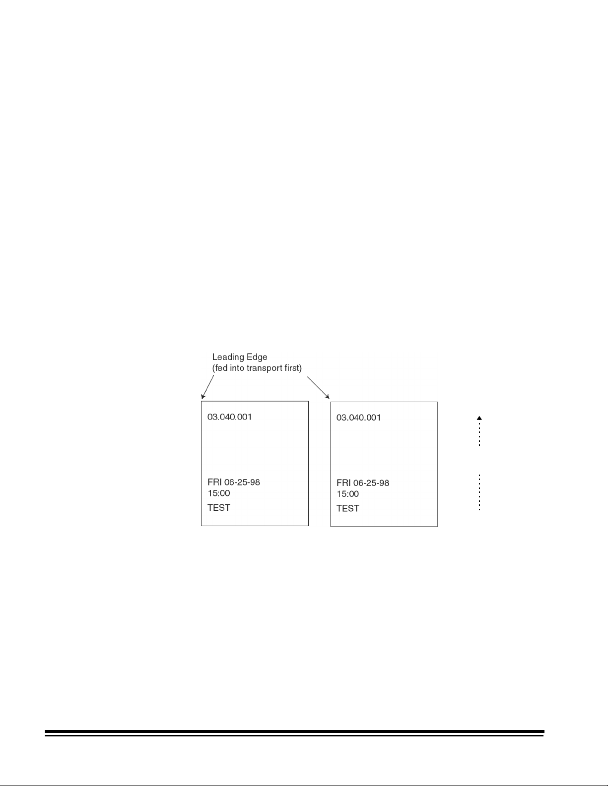
The information printed by the Super12 Document Printer always
appears in rows parallel to the leading edge of the document(s) as
shown:
Document travels
through transport
Orientation — information is printed on each document in Comic
orientation.
Font — only one font is available for the Super12 Document Printer.
IMPORTANT:
The Super12 Document Printer allows you to print only
up to line 15 (relative to the print template, which is used
in conjunction with print position to determine distance
of the printed information from the leading edge of the
document).
2 A-61121 May 1999
Page 4
Changing the print location and print position
Super12
Document Printer
The location of the information you want printed on a document is
determined by the print location of the Super12 Document Printer and
the pre-defined print position.
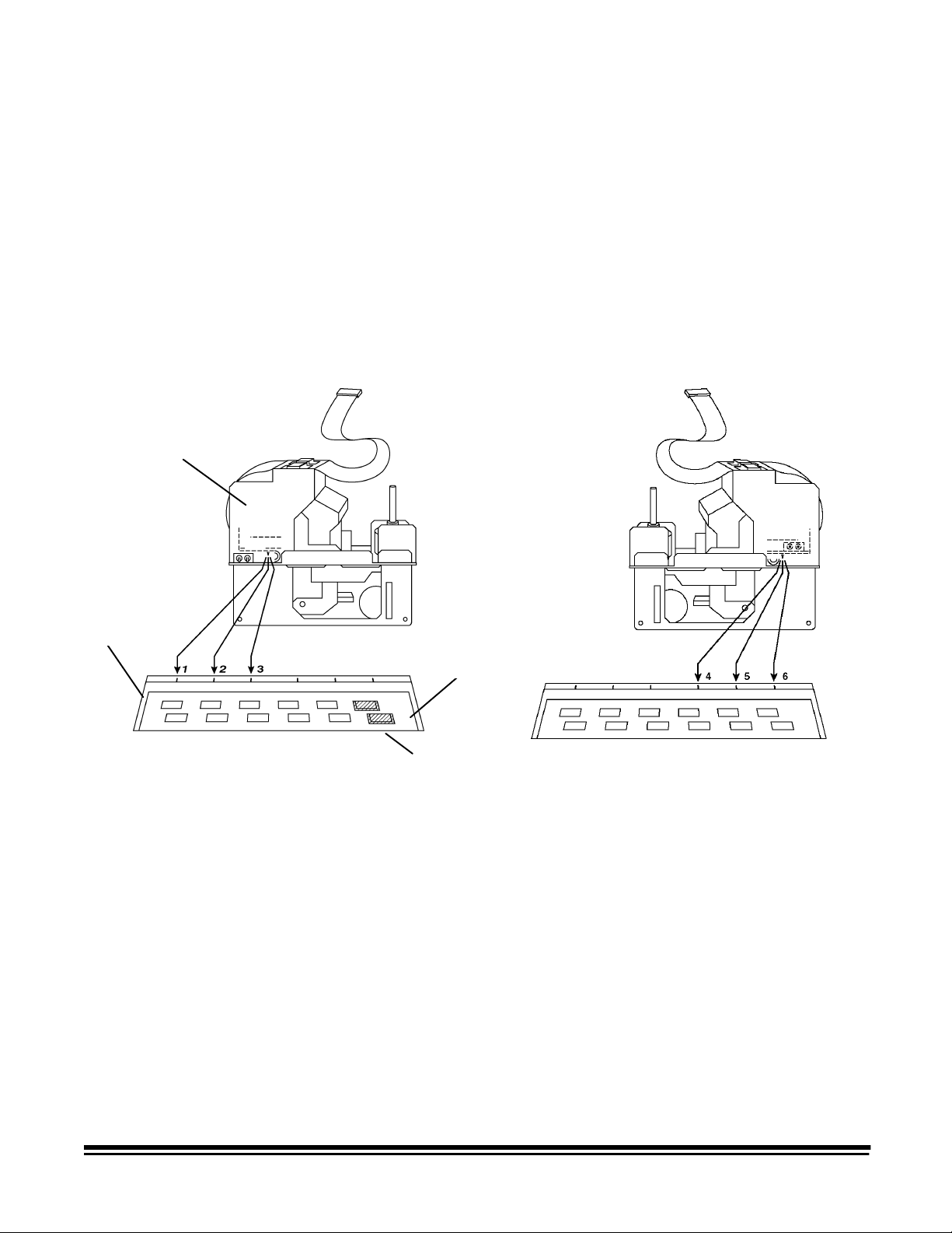
Print Location
The Super12 Document Printer can be placed in one of six available
locations across the transport plate. The orientation of the printer when
in position 1, 2 or 3 is different than when the printer is in position 4, 5
or 6.
Printer bracket
Transport
plate
Plastic strips cover print
locations
NOTE: Before you change print locations, remove the plastic strips
covering the print locations you want to print in. The plastic
strips cover the print locations on both the transport plate and
the belt module (not shown in this illustration). Plastic strips
should be left in place for any unused locations.
A-61121 May 1999 3
Page 5
To remove the plastic strips from a print location:
1. Open the front cover of the scanner.
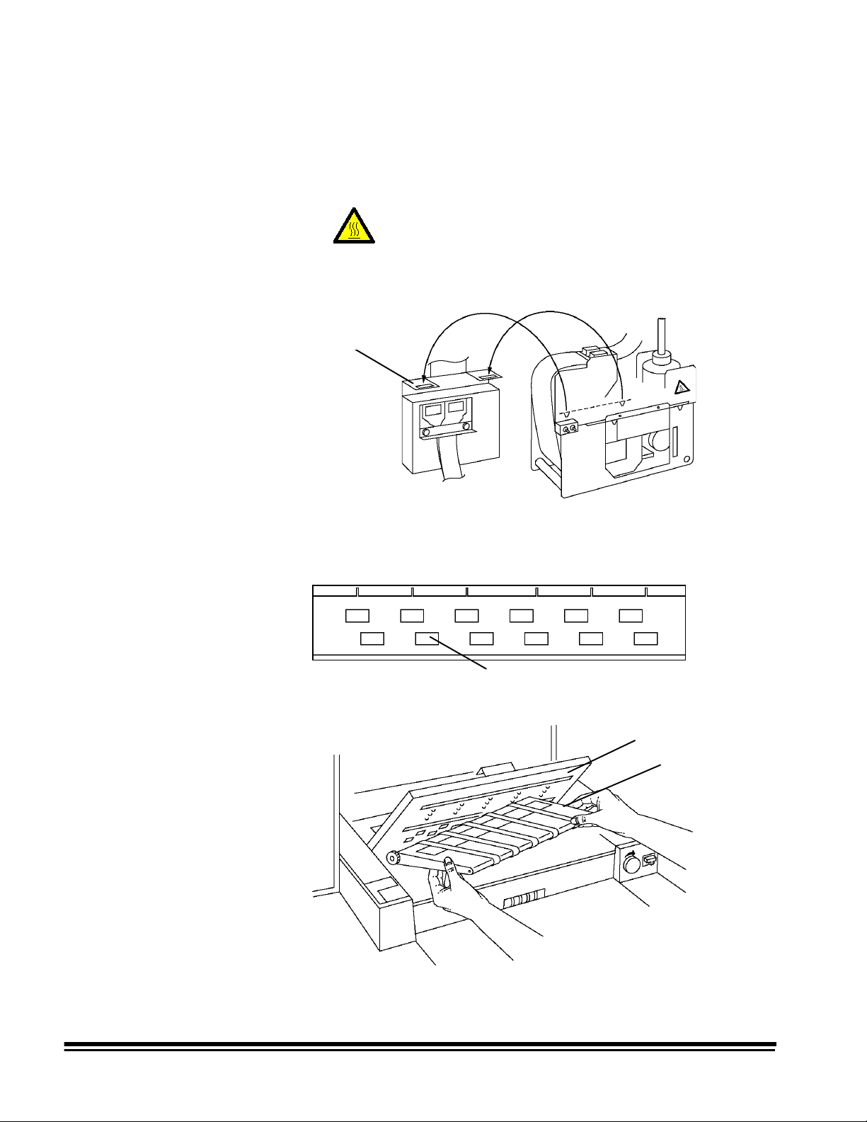
2. Lift the printer f rom the printer bracket and place it on the hanger
bracket to keep it out of the way.
CAUTION: Hot surface, avoid contact.
NOTE:Be sure the flex cable is placed between the two hooks so it
does not get damaged.
Hanger bracket
3. Remove the plastic strips from any print locations (on the transport
plate) that you will be printing in.
Plastic strips
4. Lift the transport plate and remove the belt module.
Transport plate
Belt module
4 A-61121 May 1999
Page 6
5. Remove the plastic strips from the desired print locations from the
underside of the belt module. The print locations that you remove
the plastic strips from should correspond with the strips you
removed from the transport plate.
Plastic strips
NOTE:Verify that the maintenance tray is in place before
continuing. If the maintenance tray is not in place, see
“Replacing the maintenance tray” for more information.
6. Replace the belt module.
7. Lower the transport plate.
8. Lift the printer from the hanger bracket, rotate it 180° if necessary,
and place it into the desired print location. The printer is firmly in
place if you cannot slide the printer from its location.
NOTE:If you are rotating the Super12 Document Printer, be careful
not to twist or strain the flex cable.
9. When finished, close the front cover.
A-61121 May 1999 5
Page 7
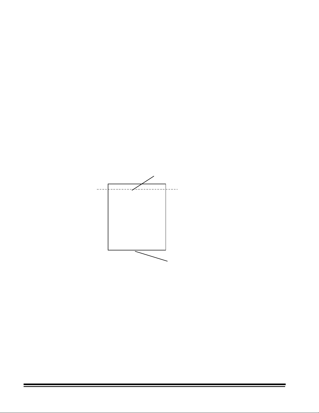
Print Position
The print position specifies how far from the leading edge (fed into the
transport first) of the document the information will be printed. The
default print position is defined at installation.
You can temporarily change the default print position by using function
code F46. The new print position will be used to print information until
function code F02 (Restore Mode) is used to return the starting print
position to its original value (provided mode overrides are not saved), or
until function code F46 is used again to change the print position(s).
NOTES:
• Restore Mode (F02) restores all initial printer settings, except the
print contrast setting and print alignment.
• The print position should be carefully calculated. Make sure to set
the print position close enough to the leading edge of the document
so the printed information is not truncated before reaching the
trailing edge of the document.
Leading edge
(fed into transport first
)
03.040.001
FRI 11-16-97
15:00
TEST
Starting print position
Trailing edge
6 A-61121 May 1999
Page 8

Enabling/disabling the Super12 Document Printer
Make sure the Super12 Document Printer is enabled before feeding
documents.
• The Super12 Document Printer may be enabled/disabled separately
at the mode level using function code F43.
• If you have enabled the Super12 Document Printer, but do not want
to print on the next document fed into the transport, you may omit
printing on the next document only by entering function code F44.
• During normal operation or a print test, the operator interface panel
will beep when the Super12 Printer has reached the capped or print
position. The beep occurs approximately 5 seconds after pressing
Run or Stop.
IMPORTANT:
Whenever Run or Stop is pressed, the Super12
Document Printer moves to a capped or print
position. The capped position covers the print
cartridges to keep them from drying out.
When Run is pressed, the message, E133 Feeder
waiting for printer will be displayed. When the
message clears and the scanner beeps, the printer
has moved into the print position.
When Stop is pressed, wait for the beep to sound
before opening the front door or turning off power,
so the printer has time to move into the capped
position
.
A-61121 May 1999 7
Page 9

Function codes
The information printed by the Super12 Document Printer is defined
during installation.
Individual modes are defined for use with specific applications. If a
Super12 Document Printer has been installed, some or all modes may
allow use of the Super12 Document Printer. In addition, the customerspecified information to be printed is defined for each mode.
The Super12 Document Printer provides easy installation and cleaning
of two print cartridges for 12-character printing. In addition to these
features, the following functions can be used:
• F39 Variable print contrast setting — allows you to increase or
decrease the amount of ink put on the document.
• F45 Print testing capability before use — allows you to test the print
quality of the Super12 Document Printer.
• F48 Auto-purging with no operator intervention — allows you to
initiate an automatic purging of the print heads. This function can be
done when the transport is off.
• F49 Print image alignment — allows you to specify how far to move
the left half of an image up or down on the document so it will align
with the right half of the image.
F39 — Changing the print contrast
• F56 Open jet/connection detection — allows you to determine
whether or not there are nonfunctional ink jets in the Super12
Document Printer. Also checks the print head(s) connection to the
flex cable to assure the print heads(s) are installed properly.
To change the print contrast setting:
1. Enter function code F39.
2. Press Enter. The current contrast setting will be displayed.
3. Press the up (↑) arrow to increment, or press the down (↓) arrow to
decrement the displayed value. Incremental values are: 12, 25, 37,
50, 62, 75, 87 and 100%.
NOTE:High contrast levels may cause ink smear on some types of
documents.
4. Press Enter to save the value.
8 A-61121 May 1999
Page 10

F45 — Verifying print quality
Perform the following procedure to verify the print quality is satisfactory:
1. Enter function code F45 (Print Test) and press Enter.
2. Press 2 (Test Pattern). The transport starts automatically.
3. Feed a blank sheet of paper; a test pattern will be printed.
4. Evaluate the appearance of the test pattern. A complete test
pattern should look similar to the following illustration:
• If the pattern is complete, begin work.
• If the pattern is not legible:
◊ Check to see that the print cartridges are inserted properly.
See the section entitled, “Installing a new print cartridge” for
more information.
◊ Perform function code F48 (Purge function) to help unclog
the print head jet openings.
◊ Repeat the print test.
5. Press 1 and verify your current mode image looks acceptable.
NOTES:
• If you select a blank print template or the No Print Template
option (depending on the specific mode you are printing in), then
the selection of 1, Current Mode Image, may print nothing.
• Print Test Pattern always prints with 100% contrast.
• The Mode Image prints with the specified contrast setting (F39).
A-61121 May 1999 9
Page 11

F49 — Aligning the print image
To align the print image so the left half of the image matches the right
half of the image:
1. Enter function code F49.
2. Press Enter. The current alignment value will be displayed.
3. Press the up (↑) arrow to move the left half of the image closer to
the leading edge of the document (the value will decrease) or press
the down (↓) arrow to move the left half of the image farther away
from the leading edge of the document (the value will increase).
4. Press Enter to save the value.
10 A-61121 May 1999
Page 12

F56 — Checking the print cartridge jet connections
To determine if all ink jets are functioning properly:
1. Enter function code F56.
2. Press Enter. The number of jets out per character, as well as the
total number of jets out, will be displayed.
Print Cartridge Status
000000000000 00
All zeros will be displayed if the ink jets on both cartridges are
operating correctly.
NOTE:If the Super12 Document Printer is in print location 1, 2 or 3,
the left 6 characters are associated with the print cartridge
that is farthest away from the orientation switch, and the right
6 characters are associated with the print cartridge that is
closest to the orientation switch.
If the Super12 Document Printer is in print location 4, 5 or 6,
the left 6 characters are associated with the print cartridge
that is closest to the orientation switch, and the right 6
characters are associated with the print cartridge that is
farthest away from the orientation switch.
Orientation switch
3. Press C to clear the display.
A-61121 May 1999 11
Page 13

Installing a new print cartridge
Before you begin, be sure the scanner is powered-on.
IMPORTANT:
Do not remove or insert print cartridges while the
printer is in the capped position. Use function code
F40, Option 1 - Change Head(s) or damage can be
done to the Super12 Document Printer.
To install a new print cartridge(s):
1. Enter function code F40 and press Enter. The following message
will be displayed:
Print Head Position
1=Change Head(s) 2=Clean Printer
2. Select 1;a
message is no longer displayed, open the front cover of the
scanner.
3. Note the current location of the Super12 Document Printer, then lift
it out of the printer bracket and place it on the feeder top cover. This
will make it easier to insert the print cartridges.
Please Wait
CAUTION: Hot surface, avoid contact.
message will be displayed. When this
Front
cover
12 A-61121 May 1999
Page 14

4. If the print cartridges are already installed, remove the cartridges.
5. Open the new print cartridge package and remove the p rint
cartridge from the package.
6. Remove the protective tape from the bottom of the print cartridge.
NOTE:Do not discard the protective tape if you plan on storing a
partially used print cartridge. You will need to place this tape
over the orifice plate on the print cartridge to keep it from
drying out.
Orifice plate
Protective tape
The small window on the side of the black print cartridge indicates if
the cartridge is empty, full or how much ink is left in the cartridge. If
the window is green, the print cartridge is full; if the window is black,
it is empty.
green
indicates Full
black
indicates Empty
Red print cartridges do not have the Full/Empty indicator, therefore,
you can weigh the print cartridge to estimate how much ink remains.
A full print cartridge weighs approximately 110 grams; an empty
print cartridge weighs approximately 70 grams.
A-61121 May 1999 13
Page 15

7. Slide a new print cartridge in the Super12 Document Printer slots,
then gently push the cartridge forward until you hear and feel it click
into place. Use the illustration below as a guide.
IMPORTANT: If changing both print cartridges, install the one
that is farthest away from the Orientation switch
first.
8. When inserting the second print cartridge, hold it closer to the
orientation switch when sliding it in place
CAUTION: Hot surface, avoid contact.
Orientation
switch
9. After the print cartridges are installed and locked into place, press
the print head continuity button. This checks that the print head is
placed correctly in the printer.
Print head
continuity
button
Flex cable lights
14 A-61121 May 1999
Page 16

If either (or both) print cartridges are not seated correctly, one (or
both) of the yellow lights on the flex cable will flash. If this happens,
repeat Steps 7 through 9 until the print cartridges are installed
correctly.
NOTE:The flashing lights on the flex cable correspond with the print
cartridge(s) that is not positioned correctly.
10. W hen the print cartridges are installed correctly, reinstall the
Super12 Document Printer in the desired print location.
NOTES
• If you are rotating the Super12 Document Printer, be careful not
to twist or strain the flex cable.
• Be sure the plastic strips are removed only from the print
locations you want to print in, from both the transport plate and
belt module. Plastic strips should be left in place for any
unused locations.
11. Close the front cover when the Super12 Document Printer is seated
properly.
12. Perform function code F45 to test the print heads.
A-61121 May 1999 15
Page 17

Maintenance
This section provides:
• Recommended cleaning guidelines.
• A list of catalog numbers and supplies needed to maintain the
Super12 Document Printer.
• Cleaning procedures for the Super12 Document Printer.
• Instructions for changing the maintenance tray.
Cleaning guidelines
Use the following information as a guide when performing routine
maintenance of the Super12 Document Printer.
The Super12 Document Printer maintenance varies with usage levels,
paper types, print contrast and the number of characters printed. The
following guidelines are recommended:
• If you scan/film less than 5,000 documents per day, perform the
maintenance procedures on the Super12 Document Printer once
every two weeks.
• If you scan/film more than 5,000 documents per day, perform the
maintenance procedures on the Super12 Document Printer once a
week.
The imaging guides, transport and sensor areas must also be cleaned
daily to maintain print quality. Ink can accumulate in any one or all of
these areas, reducing overall print quality. Cleaning may be required
more often depending upon environmental conditions or paper types.
Refer to one of the following guides for detailed cleaning procedures:
A# Description
A-61092 User’s Guide for the
Scanner 9500
Kodak Digital Science
Document
A-61096 User’s Guide for the
Scanner/Microimager 990
A-41308 User’s Guide for the
A-61603V Video Tape (PAL format) — Maintenance and Feeder
Adjustment Procedures
A-61604V Video Tape (SECAM format) — Maintenance and
Feeder Adjustment Procedures
Video tapes and technical publications can be ordered through the BIS
Customer Service Center at: 1-888-247-1234.
Rubber gaskets and the maintenance tray should be changed
approximately every six months, this will vary with usage levels.
IMPORTANT:
Do not use any cleaning solutions or solvents when
Kodak Digital Science
Kodak Imagelink
Microimager 70
Document
performing these cleaning procedures.
16 A-61121 May 1999
Page 18

Cleaning materials and supplies
Use the Super12 Maintenance Kit that comes with the Super12
Document Printer.
The Maintenance Kit contains the following:
• Cleaning swabs
• Rubber gaskets
• A maintenance tray
The following supplies are available through your Kodak sales contact.
Supply CAT No.
Super12 Maintenance Kit 165 8483
Black print cartridge (6/package) 822 1376
Red print cartridge (6/package) 145 6532
Cleaning the document printer
To clean the Super12 Document Printer, follow the steps below.
1. Enter function code F40 and press Enter. The following message
will be displayed:
Print Head Position
1=Change Head(s) 2=Clean Printer
2. Select 1;a
Please Wait
message will be displayed. When this
message is no longer displayed, open the front cover of the
scanner.
3. Note the current location of the Super12 Document Printer, then lift
it out of the printer bracket and place it on the feeder top cover.
CAUTION: Hot surface, avoid contact.
4. Remove the print cartridges. If there is any ink build-up on the print
cartridges, clean it with a swab.
5. Place the printer back in the desired print location.
6. Close the front cover.
A-61121 May 1999 17
Page 19

7. Enter function code F40 and press Enter. The following message
will be displayed:
Print Head Position
1=Change Head(s) 2=Clean Printer
8. Select 2;a
Please Wait
message will be displayed. When this
message is no longer displayed, open the front cover of the
scanner.
9. Lift the printer out of the printer bracket and place it on the feeder
top cover.
10. With a supplied swab, wipe off the rubber gaskets and the area
around the gaskets.
NOTE:The rubber gaskets can be removed and cleaned.
Periodically, it may be necessary to replace the rubber
gaskets with a new set. Make sure the gaskets are seated
properly before continuing.
Gaskets
Wipers
11. W ipe off any ink build-up on the rubber wipers.
12. Tilt the Super12 Document Printer, as illustrated, and wipe the flex
cable connectors and splatter guards.
Splatter guards
Flex cable connectors
13. When finished, place the Super12 Document Printer into the
desired print location.
14. Close the front cover.
18 A-61121 May 1999
Page 20

To replace the print cartridges:
15. Enter function code F40 and press Enter. The following message
will be displayed:
Print Head Position
1=Change Head(s) 2=Clean Printer
16. Select 1;a
Please Wait
message will be displayed. When this
message is no longer displayed, open the front cover of the
scanner.
17. Lift the printer out of the printer bracket and place it on the feeder
top cover.
18. Reinsert the print cartridges.
19. Press the print head continuity button to verify both print cartridges
are installed correctly.
Print head
continuity button
20. Replace the Super12 Document Printer to the desired print location.
21. Close the front cover.
A-61121 May 1999 19
Page 21

Cleaning the transport area
To thoroughly clean the transport area, perform the following procedure:
1. Open the front cover.
2. Note the current location of the Super12 Document Printer, then lift
it from the printer bracket, being careful not to strain the flex cable.
3. Place the Super12 Document Printer on the hanger bracket to keep
it out of the way while you are cleaning other areas of the machine.
CAUTION: Hot surface, avoid contact.
NOTE:Be sure the flex cable is placed between the two hooks so it
does not get damaged.
Hanger bracket
The following illustrations show the transport areas which need to be
cleaned and how to clean them:
1. Lift the transport plate.
2. Wipe the transport plate surfaces with a slightly water-dampened,
lint-free cloth to remove any ink deposits. Ensure that the topside of
the print locations are clean.
3. Wipe the bottom of the transport plate thoroughly with a slightly
water-dampened, lint-free cloth. Make certain that the underside of
the print locations are clean.
4. Insert the Super12 Document Printer into the desired position in the
transport plate, being careful not to strain the flex cable.
5. Close the front cover.
20 A-61121 May 1999
Page 22

Replacing the maintenance tray
Periodically the Super12 Document Printer maintenance tray may need
to be replaced.
To access and replace the maintenance tray:
1. Open the front cover of the scanner.
2. Place the printer on the hanger bracket so it is out of the way.
CAUTION: Hot surface, avoid contact.
Hanger bracket
NOTE:Be sure the flex cable is placed between the two hooks so it
does not get damaged.
3. Lift and lock the transport plate into place.
4. Lift and remove the belt module and place it aside.
Transport plate
Belt module
A-61121 May 1999 21
Page 23

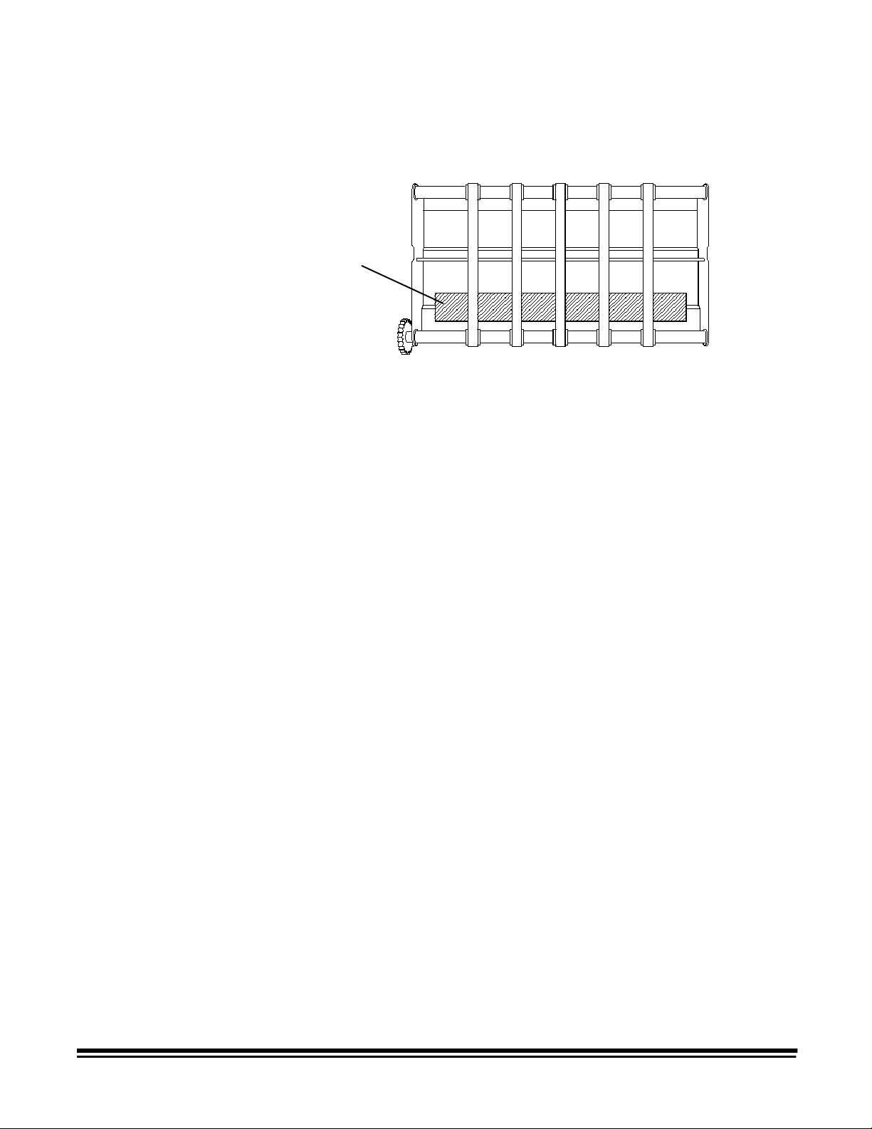
5. Lift out the used maintenance tray and dispose of it according to
your local and state regulations.
Maintenance tray
6. Open the package containing the new maintenance tray and
remove it.
7. Insert the new maintenance tray; be sure it is firmly in place. The
alignment blocks on the bottom of the maintenance tray should be
placed around the two angled brackets as shown:
When the maintenance tray is seated correctly, the ink spray from
the Super12 Document Printer should be deposited in the center
area of the foam in the maintenance tray.
6. Re-install the belt module.
7. Unlock and replace the transport plate.
8. Remove the printer from the hanging bracket and place it in the
proper print location.
9. Close the front cover.
22 A-61121 May 1999
Page 24

Storage and handling of print cartridges
If unused print cartridges are going to be stored for a period of time,
replace the protective tape on the orifice plate of the print cartridge.
Orifice plate
Protective tape
NOTE: Dispose empty print cartridges according to your local and state
regulations.
A-61121 May 1999 23
Page 25

Troubleshooting
Problem Solution
This section lists possible problems you may encounter when using the
Kodak Digital Science
Super12 Document Printer.
Printing a partial image or printing
backwards
Experiencing print problems at startup
due to heads drying up
Image is drifting from the desired print
location
Poor print quality If you are experiencing poor print quality, check the
Be sure the Super12 Document Printer is seated correctly
on the printer bracket.
• Press Stop and wait approximately 5 seconds for the
Super12 Document Printer to reach the capped position
before opening any doors, performing any printer
functions or turning off any switches.
• Press F48 (Auto Purge).
• Press F45 (Test Pattern).
See the next section entitled “How print position is effected
by patch reading” for more detailed information.
following:
• Check to be sure the print cartridges are not empty.
If you are using a black print cartridge, check the
Full/Empty indicator to see how much ink remains in the
cartridge. If it is empty, insert a new print cartridge.
If you are using a red print cartridge, weigh the print
cartridge to be sure it has an adequate ink supply; a full
print cartridge weighs approximately 110 grams; an
empty print cartridge weighs approximately 70 grams.
• Use F56 to verify that all jets are functioning properly.
• Clean the wipers and gaskets. See the procedures in
the section entitled, “Maintenance”.
When finished:
• Press F48 (Auto Purge).
• Press F45 (Test Pattern).
24 A-61121 May 1999
Page 26

How print position is effected by patch reading
Patch Reading OFF — Print Position 0.25 inch
Print Position
The ability to print at the designated print position will be effected by
patch reading, and by the amount of printed information which changes
for each document. If you encounter print position drift, it may be
necessary to change your print template using the Mode Setup
Software or change your current print position further down the page.
Following are some examples illustrating print drifting with Patch
Reading turned off and on.
Patch Reading turned off
The following illustration shows the print position when 1 to 3 half or full
print lines have been changed with Patch Reading turned off.
NOTE: A half print line consists of 6 characters; a full print line consists
of 12 characters.
Print position drifting occurs when more than 3 full print lines need to
change.
2 half print lines
changed
2 full print lines
changed
3 half print lines
changed
3 full print lines
changed
Patch Reading turned on
If Patch Reading is turned on, and if the print position exceeds 1 inch,
then the patch window will be forced to 4 inches. Patches must be
within the first 4 inches of the document. Following is a table indicating
print positions and patch window size.
Print Position Patch Window Close
.125 inches 2.5 inches after lead edge
.25 inches 2.5 inches after lead edge
.375 inches 2.5 inches after lead edge
.50 inches 2.5 inches after lead edge
.625 inches 2.5 inches after lead edge
.75 inches 2.5 inches after lead edge
.875 inches 2.5 inches after lead edge
1 inch 4 inches after lead edge
more than 1 inch 4 inches after lead edge
A-61121 May 1999 25
Page 27

If the print position is set at less than 1 inch, the patch window will close
¾
t
at 2.5 inches after the lead edge; the printer can change up to 1 full
print line and be able to print at the designated position. However, if
more than 1 full print line needs to be changed, the image may drift
down the page depending on how much more information needs to be
changed.
Patch Reading ON — Print Position 0.25 inches — Patch Window is 2.5 inches
Print Position
Approximately
¾-inch drift
Approximately
¼-inchdrift
Approximately
1
-inchdrif
1 half print
line changed
1 full print line
changed
2 half print
lines changed
2 full print
lines changed
If your document is longer than 3 inches and the print position is set at
1 inch, the patch window will close at 4 inches after the lead edge; the
printer can change up to a half print line and be able to print at the
designated position. However, if more than a half print line needs to be
changed, the image may drift down the page depending on how much
more information needs to be changed.
Patch Reading ON — Print Position 1 inch — Patch Window is 4 inches
PrintPosition
Approximately
½-inch drift
Approximately
½-inch drift
Approximately
1½-inch drift
3 half print
lines changed
Approximately
1-inch drift
3 full print
lines changed
Approximately
2 ½-inch drift
1 half print
line changed
1 fullprint line
changed
2 halfprint
lines changed
2fullprint
lines changed
3 half print
lineschanged
3fullprint
lines changed
For example, if 2 full print lines need to be changed, the image may
print 1.5 inches further down the page; not at the designated 1 inch.
NOTE: Print drift may occur if you use function codes F39 or F49 while
the transport is running.
26 A-61121 May 1999
Page 28

Error codes
Following is a list of errors codes you may encounter when using the
Super12 Document Printer.
Error: E133 Feeder waiting for printer.
Probable cause: The feeder will not be ready until the printer has
moved to the print position.
Solution: Wait until the printer has moved into the print position.
Error: E206 Check Print Cartridge(s)
Probable cause: This error may be displayed for one of the following
reasons:
• Either no print cartridge(s) is installed or one or both print
cartridge(s) may be installed but not making a good connection.
• The print cartridge may be defective.
• The flex cable may not be working properly.
Solution: Be sure the print cartridges are seated correctly and that they
are making a good connection.
1. Enter function code F56 to determine if more than 10 jets are out on
any one or more characters.
2. Press F40 and select Option 1, Change Heads.
3. Open the front cover of the scanner.
4. Lift the printer out of the printer bracket. One or both of the flex
cables lights will be blinking.
5. Determine which print cartridge is not making a good connection.
The blinking light(s) on the flex cable correspond with the print
cartridge that is not seated correctly.
6. Reinstall the print cartridges.
IMPORTANT:
When installing the print cartridges, be sure you
hear and feel the print cartridge click into place.
7. Press the print head continuity button. If the flex cable lights stop
flashing, a good connection is made.
8. Place the printer back in the desired print location and close the
door.
A-61121 May 1999 27
Page 29

If E206 continues to be displayed or the flex cable lights continue to
flash, enter F45 to do a Print Test. If the print quality is acceptable,
ignore the E206 error or the flashing flex cable lights.
If the print quality is not acceptable, try changing one or both of the print
cartridges, then enter F45 again to do another Print Test.
If the print quality is still not acceptable, the flex cable may not be
working properly. Call service.
Error: E806 Printer System Error
Probable cause: One or both print cartridges may be seated
incorrectly.
Solution: Be sure the print cartridges are seated correctly. If the
problem persists, replace the print cartridges. If E806 continues to be
displayed, call service.
Error: E810 Printer System Error
Probable cause: If you encounter this error and the system is still
working, then the print template is longer than 15 lines.
Solution: Enter Mode Setup Software and redefine the print template. If
you do not have Mode Setup Software, call service.
If you encounter this error and the system is not working, call service.
Error: E813 Printer System Error
Probable cause: This is a motor error; something has stopped the
progress of the motor in the Super12 Document Printer.
Solution: Perform the following steps:
1. Open the front door and clear any items that could block or interfere
with the swing arm.
2. Close the front door. The printer will move into the capped position
and any errors should clear.
If the error persists, call service.
28 A-61121 May 1999
Page 30

A-61121 Part No. 1H7191 3/99
©Eastman Kodak Company, 1999
Printed in U.S.A.
EASTMAN KODAK COMPANY
Document Imaging
Rochester, New York 14650
Kodak, Imagelink, Digital Science and
the ds monogram symbol are
trademarks of Eastman Kodak
Company.
Printed on recycled paper.
DOCUMENT
IMAGING
 Loading...