

Page 1

Scanners
Patch Code Information
A-61599
CAT No. 845 9380
A-61599
October 2006
Page 2
Patch Code Information for Kodak Scanners
Patch description
This document provides information that supports the following scanners.
• Kodak Scanners 9XYZ, 5XYZ, 7XYZ, i800/i1800 (with image addressing) Series Scanners and the
Kodak Microimager 70—these scanners are equipped with the Patch Reader. The Patch Reader recognizes
patches with bars that are parallel to the lead edge of the document. All of these scanners may use patches
for image addressing. In addition, the i800/i1800 (with image addressing) Series Scanners may use toggle
patches for Color on the Fly functionality.
• Kodak Scanners i280, 3590C and i600/i1800 (without image addressing) Series Scanners—these
scanners are not equipped with a Patch Reader. These scanners recognize patches with bars that are per-
pendicular to the lead edge of the document. These scanners will only recognize the toggle patch for Color on
the Fly functionality and do not have image addressing.
A patch is a pattern of parallel, alternating black bars and spaces that is printed on a document.
Kodak Scanners which have patch reading capability can recognize patch documents
and automatically assign a document image level, increment the document image address, or perform Color on
the Fly functionality.
The wide bars should be 0.20 inches (5 mm) wide
be 0.08 inches (2.03 mm) wide
(20 mm)
+0.01 inches (0.25 mm). The minimum overall length of the patch bars is 2 inches (50 mm).
+ 0.01 inches (0.25 mm). The maximum width of the patch code is 0.80 inches
NOTE: The patch codes illustrated below are not to spec. Use the patch sheets included in this packet for
specifications.
Patch Codes
Patch 2
Patch code specifications
Patch 2
Assigns image level 2 to the
current document.
+ 0.01 inches (0.25 mm). The narrow bars and spaces should
Zone Millimetres
A
B
C
D
E
F
G
A 0.19 0.21 4.83 5.33
B 0.27 0.29 6.86 7.37
C 0.35 0.37 8.89 9.40
D 0.43 0.45 10.92 11.43
E 0.51 0.53 12.95 13.46
F 0.59 0.61 14.99 15.49
G 0.79 0.81 20.07 20.57
Inches
Low
Range
High
Range
Low
Range
High
Range
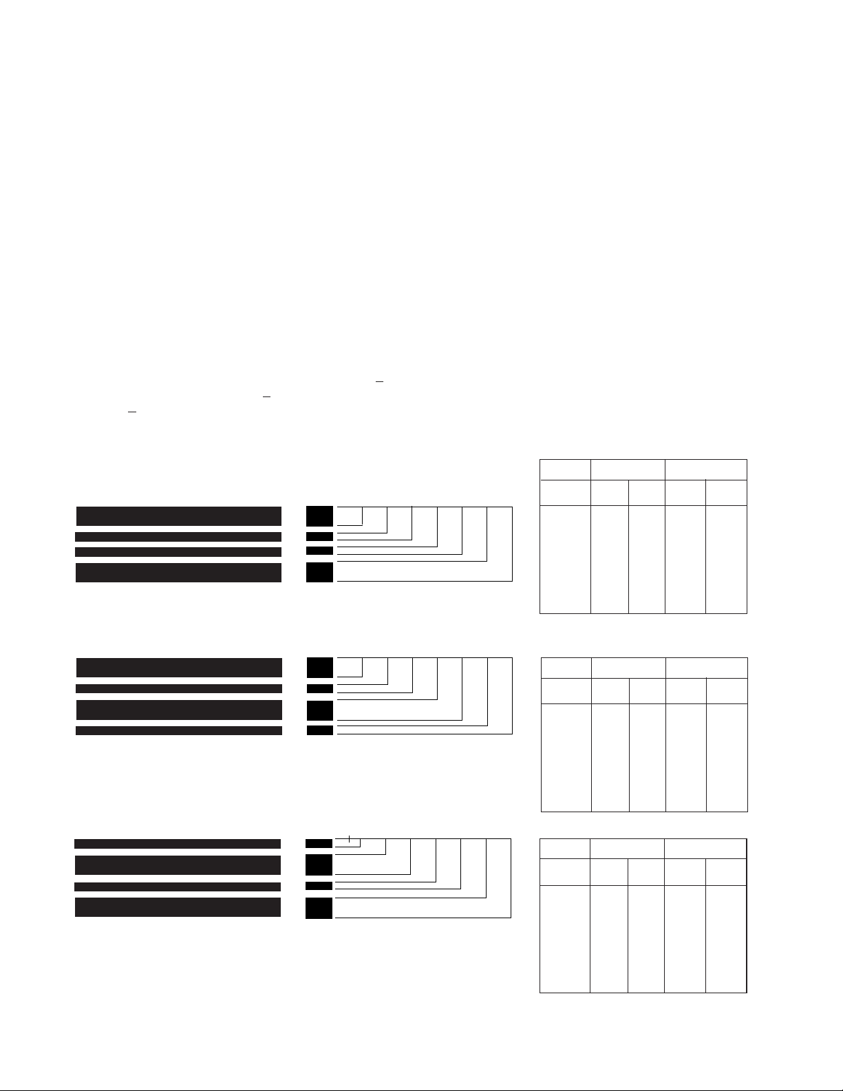
Patch 3
Assigns image level 3 to the
current document.
Patch T / Transfer Patch
Assigns a predefined image level
to the next document. The
predefined image level is based
upon the transfer patch definition
which is defined for each applica-
Patch 3
A
B
C
D
E
F
Patch T / Transfer Patch
A
B
C
D
E
F
tion. For example, if the transfer
patch definition is image level 2,
then use of a transfer patch
assigns image level 2 to the next
document.
Zone Inches Millimetres
High
High
Low
Range
Low
Range
Low
Range
Range
G
G
A 0.19 0.21 4.83 5.33
B 0.27 0.29 6.86 7.37
C 0.35 0.37 8.89 9.40
D 0.43 0.45 10.92 11.43
E 0.63 0.65 16.00 16.51
F 0.71 0.73 18.03 18.54
G 0.79 0.81 20.07 20.57
Zone Inches Millimetres
Low
Range
Range
A 0.07 0.09 1.78 2.29
B 0.15 0.17 3.81 4.32
C 0.35 0.37 8.89 9.40
D 0.43 0.45 10.92 11.43
E 0.51 0.53 12.95 13.46
F 0.59 0.61 14.99 15.49
G 0.79 0.81 20.07 20.57
High
Range
High
Range
Page 3
Patch Types 1, 4 and 6 can be used by the host for post-scan image control for the i800/i1800 (with image
addressing) Series Scanners (they are not used for image addressing).
The Toggle Patch may be used to switch back and forth from bi-tonal and color/grayscale scanning for the
i280, 3590C, i600, i800 and i1800 (without image addressing) Series Scanners. This provides Color on the
Fly during capture, with no need for post-scan processing by the host application.
NOTE: The patch codes illustrated below are not to spec. Use the patch sheets included in this packet for
specifications.
Patch Codes
Patch code specifications
Patch 1 Patch 1
Patch 4/Toggle Patch
Patch 4/Toggle Patch
Zone Millimetres
Inches
Low
Range
High
Range
Low
Range
High
Range
A 0.19 0.21 4.83 5.33
B 0.27 0.29 6.86 7.37
C 0.47 0.49 11.94 12.45
D 0.55 0.57 13.97 14.48
E 0.63 0.65 16.00 16.51
F 0.71 0.73 18.03 18.54
G 0.79 0.81 20.07 20.57
Zone Inches Millimetres
High
Low
Range
Range
Low
Range
Range
High
A 0.07 0.09 1.78 2.29
B 0.15 0.17 3.81 4.32
C 0.35 0.37 8.89 9.40
D 0.43 0.45 10.92 11.43
E 0.63 0.65 16.00 16.51
F 0.71 0.73 18.03 18.54
G 0.79 0.81 20.07 20.57
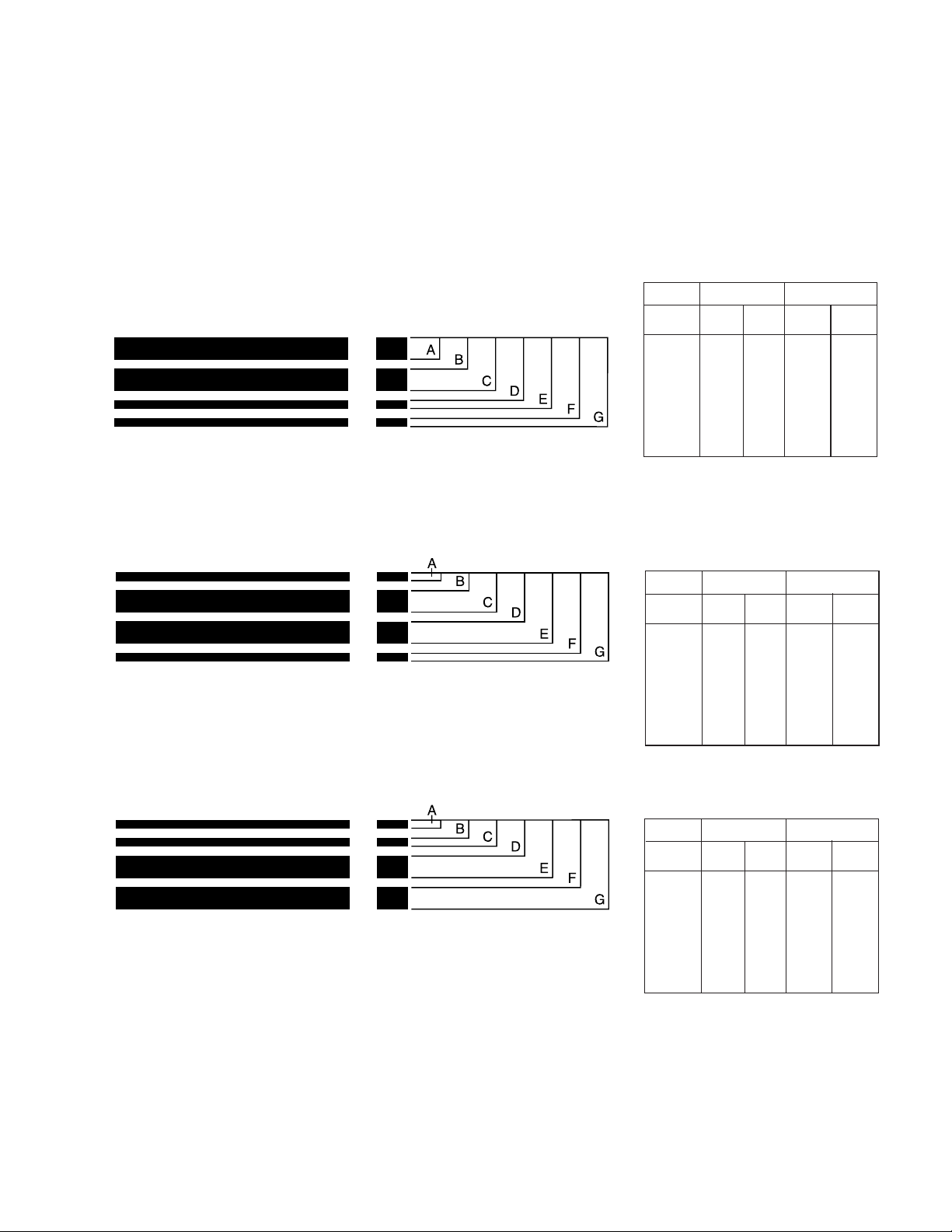
Patch 6
Patch 6
Zone Inches Millimetres
High
Low
Range
Range
Low
Range
Range
High
A 0.07 0.09 1.78 2.29
B 0.15 0.17 3.81 4.32
C 0.23 0.25 5.84 6.35
D 0.31 0.33 7.87 8.38
E 0.51 0.53 12.95 13.46
F 0.59 0.61 14.99 15.49
G 0.79 0.81 20.07 20.57
Page 4

For Kodak Scanners 9XYZ, 5XYZ, 7XYZ, i800/i1800 (with image addressing) Series Scanners
and 70 Microimager:
The minimum overall length of the patch bars is 2 inches (50 mm).
Patch positioning
Horizontal and vertical placement of the patch code
is critical for proper operation. If the patch code is
placed improperly on the document, the patch
sensors may fail to sense the patch.
• Patches should appear with the bars parallel to
the leading edge of the document (fed into the
transport first).
• There must be at least 0.25 inches (6 mm) of
space between the patch code and any other
printed information.
Horizontal placement/positioning
• There are five patch sensor locations for the
scanner models listed above, except for the i1800
Series Scanners which have four patch sensor
locations.
• Horizontal placement of patch codes is affected by
the position of the side guides. Make certain the
side guides are positioned so the patch code will
be transported directly past the window in which
the patch reader is installed.
• Use of a standard 2.5-inch (62.5 mm) patch code
is recommended to ensure the patch code may
still be read even if there is a slight variation in the
positioning of the side guide(s).
Refer to Figure A.
Figure A
Center of Transport
Page 5

Leading Edge of Document
(fed into transport first)
A
Vertical placement/positioning
• Patch codes must appear at least 0.25 inches
(6 mm) from the right, left, and leading edges of
the document.
• Patch codes must appear no more than 3.75
inches (94 mm) from the leading edge of the
document [1.6 inches (40 mm) on the 5XYZ and
7XYZ Scanners].
Refer to Figure B.
BC
3.75 inches (94 mm)
Patch Area
Figure B
A, B, and C = 0.25 inches (6 mm)
Patch Reader Positions
for 9XYZ, 5XYZ, 7XYZ,
i800 Series Scanners
and 70 Microimager
Patch Reader Positions
for i1800 Series Scanners
(with image addressing)
Page 6

For i280, 3590C and i600/i1800 (without
image addressing) Series Scanners
The minimum overall length of the patch bars is
0.75 inches (19 mm).
Patch Positioning
Horizontal and vertical placement of the patch
code is critical for proper operation. If the patch
code is placed improperly on the document, the
scanner may fail to read the patch.
• Patches should appear with the bars perpendicular to the lead edge of the document (fed
into the transport first).
• Any other (non-patch) printed information to the
left or right of the patch could cause false
readings (see “E” on the illustration).
• Patch codes must be at least 0.25 inches (6 mm)
from the left and right edge of the document and
must appear at least 0.5 inches (12.7 mm) from
the lead edge of the document.
• The Patch Reading Area ends 2.0 inches from the
lead edge of the document. At least 0.75 inches of
the patch code must appear within the Patch
Reading Area.
For All Scanners
Printing specifications
A patch code is a parallel pattern of bars (black,
low reflectance) and spaces (clear, high
reflectance).
The ink used to print the black bars must be
carbon-based black or equivalent. The printed
black bars must reflect less than 20% of the light
source.
The bond paper that forms the spaces must be
white or a light pastel color that reflects at least
65% of the light source.
This package contains several pages of cameraready patch codes. These copies adhere to the
specifications provided and may be used by a
printer when creating patch documents.
Two types of camera-ready patch codes are
provided:
• 2.5-inch (62.5 mm) long patch codes which may
be used when preprinting patch code labels or
when printing patch codes directly on application documents.
Reliability requirements
• Print the patch code only on the top page of
multiple-part forms with carbon paper inserts.
Smudged carbon in the patch code area can
cause false readings.
• If patch-coded forms are printed in pads, make
sure the torn edges are not fed into the machine
first (not the leading edge). A ragged leading edge
preceding the patch code may cause the distance
to the first bar to be out of tolerance.
• Avoid photocopying patches. Photocopiers tend
to increase the size of the black bars while
simultaneously reducing the white space, thus
altering the print specifications.
• Print patch codes with carbon-based ink.
NOTES: Ink which is used to print bar codes
typically has a high carbon content.
Soy-based inks are not recommended.
• Avoid printing patches on glossy paper. Glare can
cause the patch to be misread.
• Full-page width and full-page length patch code
documents which may be used to create fullpage patch documents which are used as batch
headers; interleaved among application documents. These full-page patches may be fed into
the transport without regard to orientation.
Page 7

Page 8

A-61599 10/06
Printed in U.S.A.
Eastman Kodak Company
Document Imaging
Rochester, New York 14650
© Kodak,2006. Kodak is a
trademark Kodak.
 Loading...