

Page 1

Page 2

1 Introduction
The Kodak i1800 Series Scanners are high-volume production
scanners which include image processing technology that can improve
image quality and sometimes make the reproduction better than the
original.
You can use the ISIS Driver or TWAIN Datasource (both are available
on the CD that is included with the scanner) or Kodak Capture Software
to enable image processing.
Other popular scanning applications are also compatible with these
scanners, however these applications may not be able to access all of
the image processing options. Please refer to your vendor’s
documentation for specific information.
The Kodak i1800 Series Scanners provide both color/grayscale and
black and white scanning simultaneously with throughput speeds up to
200 ppm.
About this manual This manual provides the following:
Chapter 1, Introduction includes a brief summary of the Kodak i1800
Series Scanners.
Chapter 2, Best Practices includes information to use when setting up
applications, recommendations on how to handle jam recoveries,
image addressing information, controlling print streams, electronic color
drop-out and much more.
Chapter 3, Using the TWAIN Datasource includes information on using
the dialog boxes presented by the TWAIN Datasource and an
explanation of the fields on each tab.
Chapter 4, Using the ISIS Driver includes information on using the tabs
presented by the ISIS driver and an explanation of fields on each tab.
Appendix A, TWAIN Image Processing Terminology — the TWAIN
Datasource for the Kodak i1800 Series Scanners have been updated to
include new terminology for traditional Kodak image processing
functions. See this appendix for a comparative chart to map between
terms.
NOTE: The scanned images used in this guide were selected for the
challenges presented to a typical scanner due to the lowcontrast characteristics of the images.
A-61580 November 2007 1-1
Page 3

Image outputs The i1800 Series Scanners are duplex scanners. This means both the
front and the rear side of each document may be captured. For each
side captured, the scanner creates a black and white and color/
grayscale image. The host application controls which of these images is
transferred to the host to be stored as an image file.
The Kodak i1800 Series Scanners can return black and white,
grayscale or color images to the host. Below is a description of the valid
combinations.
• Front black and white: FB.tif. This image file represents the
contents of the front side of the document using one-bit per pixel.
• Front color: FC.jpg. This image file represents the contents of the
front side of the document using 24-bits per pixel.
• Back black and white: BB.tif. This image file represents the
contents of the rear side of the document using one-bit per pixel.
• Back color: BC.jpg. This image file represents the contents of the
rear side of the document using 24-bits per pixel.
NOTE: Actual file formats are determined by the host application.
These image files can be controlled through the application
independently.
FB.tif
(front black and white)
FC.jpg
(front color)
BB.tif
(back black and white)
BC.jpg (
back color)
1-2 A-61580 November 2007
Page 4

Another example of a simultaneous output where all four images are
returned to the host would create the following four files:
• Front grayscale: FG.jpg. This image file represents the contents of
the front side of the document using 8-bits per pixel.
• Front black and white: FB.tif. This image file represents the
contents of the front side of the document using 1-bit per pixel.
• Back grayscale: BG.jpg. This image file represents the contents of
the rear side of the document using 8-bits per pixel.
• Back black and white: BB.tif. This image file represents the
contents of the rear side of the document using 1-bit per pixel.
NOTE: Actual file formats are determined by the host application.
These image files can be controlled through the application
independently.
FG.jpg
(front grayscale)
FB.tif
(front black and white)
BG.jpg
(back grayscale)
BB.tif
(back black and white)
A-61580 November 2007 1-3
Page 5

2 Best Practices
This chapter provides you with recommendations for program logic,
which will allow you to interact efficiently with the i1800 Series
Scanners. This high-level information is not intended to be used as a
coding guide. The following information is provided in this chapter:
• Basic image capture
• Switching between color/grayscale and black and white
• Jam recovery
• Image file storage locations
• Bar code recognition
• Controlling print strings
• Electronic Color Dropout (form design, drop-out colors)
• Available image header information and its uses
• Zone processing (recombining images, especially for viewing)
• Programmable keys
• Starting image addresses
• Patch reading
•Batching
NOTE: The term host in the sections that follow refers to either the
driver or application.
Basic image capture Basic image capture is a high-level logic flow for retrieving images from
the scanner.
Follow this sequence to scan documents:
• set up the scanner,
• enable scanning,
• initiate polling,
• feed documents
• and disable scanning.
A-61580 November 2007 2-1
Page 6

Scanner setup To set up the scanner:
1. Set up your scanner operating conditions:
• simplex/duplex
• image order
• lamp timeout
• transport timeout
• transport timeout response
• length detection status and response
• multi-feed detection status and response
• starting document count
• printing parameters (printing status, print font, orientation and
strings)
• programmable keys
• batching parameters (batch level, count, start and end-of-batch
functions)*
• patch parameters (patch types to recognize, transfer patch
definition)*
• starting image address*
• level to follow level rules*
• image address formats*
*These items are only available when Image Addressing is enabled.
For information on programming these conditions, see Chapters 3
or 4 (depending on your driver). For other vendor tool kits, refer to
their documentation.
2. Select your Document Type/Color Correction as appropriate for
color document scanning. See Chapters 3 or 4 (depending on your
driver). For other vendor tool kits, refer to their documentation.
3. Determine if any changes to the Image Processing parameters
need to be made for the current application.
NOTE: This check needs to occur for up to four separate images
from the six available options depending on your
application: Front Color, Front Black and white, Front
Grayscale, Back Color, Back Black and white, Back
Grayscale.
Image Processing parameter changes remain in effect until one of
the following conditions occur:
−The scanner is powered down using the power switch.
−New imaging parameters are sent from the host.
4. Prepare documents according to the instructions found in the Kodak
i1860 User’s Guide.
2-2 A-61580 November 2007
Page 7

Enable scanning The host must issue a Scan command to enable scanning before
documents can be transported through the scanner. If scanning has not
been enabled, the feeder and transport system will not turn on.
Initiate polling Initiate host system polling of the scanner to ensure scanned document
images are transferred from the image buffer to the host system.
Polling should continue until scanning is disabled.
For more information see the sections entitled, “Controlling image
transfer order” and “Image header information” later in this chapter.
Feed documents Feed documents according to the instructions found in the Kodak i1800
Series Scanners User’s Guide.
Disable scanning Scanning is disabled to allow the host to download configuration/setup
changes between jobs and to handle certain types of errors.
Scanning is also disabled when one of the following conditions occur:
• The scanner is first powered on using the power switch.
• An End-of-Job indicator is sent by the operator from the operator
control panel touchscreen.
• A scanner-unique End-of-Job command is issued by the host
computer.
• An error occurs requiring fault recovery.
NOTE: When scanning is disabled, documents cannot be scanned until
the host enables scanning.
Error handling The scanner recognizes and reports a variety of error conditions.
Some errors are reported to either the host or the touchscreen, while
others are reported to both the host and the touchscreen.
An error is defined as either a current or deferred error.
A current error results from a problem in processing the current
command. This can include sending an invalid command, trying to read
from an empty image buffer, or an end-of-job condition. Since one or
more errors may be pending at any time, current errors are reported
first.
A deferred error results from an error condition within the scanner, such
as a document jam. Deferred errors that may have occurred are
reported after current errors.
NOTE: Low level commands and information will be handled by your
device driver. The following information is provided for reference
only.
When an error occurs, the host will receive a Check Condition Status.
This indicates to the host that there may be one current error and
potentially one or more deferred errors. The host must follow a Check
Condition Status with a Request Sense command. The Sense data will
indicate the type of error that has occurred.
A-61580 November 2007 2-3
Page 8

To receive subsequent pending errors, the host must execute a Test
Unit Ready command. If a deferred error is pending, the Test Unit
Ready command will terminate with a Check Condition Status. The host
follows with a Request Sense command. The combination of Request
Sense followed by Test Unit Ready must be repeated until a "good"
status is returned on the Test Unit Ready command. A "good" status
indicates no errors (current or deferred) are pending.
IMPORTANT: If at any point the host receives a Check Condition for a
command and fails to issue a subsequent Request
Sense command, the scanner will clear all (current and
deferred) Sense data.
Some error conditions disable scanning and cause the document
transport to stop. These errors are reported on the touchscreen. This is
done to prevent additional images from entering the image buffer while
allowing the host to perform fault recovery activities.
NOTE: The scanner cannot determine exactly which images were
affected by the error and which images were not.
If an error occurs that disables the scanner, the host can continue to
read images from the image buffer without enabling the scanner.
However, when the image buffer has been emptied, an error will be
generated indicating fault recovery is required. This differentiates
between an end-of-job disable and a disable caused by an error. The
operator may continue scanning documents after the host enables the
scanner.
2-4 A-61580 November 2007
Page 9

Controlling image transfer order
This section provides job stream examples which can be used in
scanning applications.
The host application is responsible for determining the order in which
the scanner returns images. Front images must always be retrieved
before back images.
Black and white only duplex
Color only - duplex 1. Prepare documents.
1. Prepare documents.
2. Start the scanner to do black and white duplex scanning (front black
and white and back black and white).
3. Setup the scanner to retrieve black and white images.
4. Enable the scanner and start polling.
Loop
Read front black and white image header
Read front black and white image
Read back black and white image header
Read back black and white image
End loop
2. Start the scanner to do color duplex scanning (front color and back
color).
3. Setup the scanner to retrieve color images.
4. Enable the scanner and start polling.
Loop
Read front color image header
Read front color image
Read back color image header
Read back color image
End loop
Grayscale only - duplex 1. Prepare documents.
2. Start the scanner to do grayscale duplex scanning (front grayscale
and back grayscale).
3. Setup the scanner to retrieve grayscale images.
4. Enable the scanner and start polling.
Loop
Read front grayscale image header
Read front grayscale image
Read back grayscale image header
Read back grayscale image
End loop
A-61580 November 2007 2-5
Page 10

Dual stream - simplex 1. Prepare documents.
2. Start the scanner to do dual stream simplex scanning (front black
and white and front color).
3. Setup the scanner to retrieve black and white images first.
4. Enable the scanner and start polling.
Loop
Read front black and white image header
Read back black and white image
Read front color image header
Read back color image
End loop
Dual stream - duplex 1. Prepare documents.
2. Start the scanner to do dual stream duplex scanning (front black and
white, front color, back black and white and back color).
3. Setup the scanner to retrieve black and white images first.
4. Enable the scanner and start polling.
Loop
Read front black and white image header
Read back black and white image
Read front color image header
Read back color image
Read front black and white image header
Read black and white image
Read back color image header
Read color image
End loop
2-6 A-61580 November 2007
Page 11

Single-stream duplex
alternating between black
and white and color/
grayscale using the
scanner Toggle patch
The Toggle patch is a type 4 patch that is used to trigger the scanner to
switch from the current image stream (black and white) to the
alternative image stream (color/grayscale).
1. Prepare documents with a patch Type 4 before and after any color/
grayscale documents.
2. Configure image processing parameters for all four images. Before
enabling the scanner, select only the front and back black and white
images to be retrieved.
3. Configure the scanner to alternate both sides when a toggle patch is
detected.
4. Start scanning.
Images will begin in black and white and will change to color/grayscale
when the first toggle patch is detected. Images will remain color/
grayscale until the next toggle patch is detected. Images of the toggle
patch sheet will not be returned to the host unless you also enable
patch reading and select the Type 4 patch.
Single-stream duplex alternating between black and white and color/grayscale using automatic color detection
1. Configure image processing parameters for all four images. Before
initiating the scanner, select only the front and back black-and-white
images to be retrieved.
2. Enable Auto Color Detection by choosing Low, Medium, High or
Custom.
3. Start scanning.
The scanner will determine if it should return a black-and-white or color/
grayscale image based on a document-by-document analysis of the
color content.
A-61580 November 2007 2-7
Page 12

Jam and fault recovery
This section provides recommendations for application logic associated
with scanner jam and fault recovery.
If your scanner is enabled and you are polling when a document jam or
other fault occurs, use the following procedure to restart scanning.
IMPORTANT: Before beginning fault recovery, make sure all the
headers and images have been transferred from the
image buffer to the host system.
When a document jam or other fault occurs, the feeder and the
transport will stop and the scanner will be disabled.
1. When all images have been retrieved from the scanner (image
buffer empty), display the last image retrieved for operator viewing.
2. Use the image header of the last image retrieved to determine the
image address and sequential counter.
3. Use the information above +1 to seed the next image address and
sequential counter before re-enabling the scanner.
4. Instruct the operator to sort through the stack of documents being
scanned to find the document that produced the last successfully
scanned image. They must rescan all of the documents that follow
the last successfully scanned document.
5. Enable the scanner.
2-8 A-61580 November 2007
Page 13

Image file storage locations
This section provides general recommendations regarding the impact
of image file storage locations on the overall throughput of the scanner.
You can receive up to four image files per document. Decisions about
where to write these files when retrieving them from the scanner could
impact the overall throughput of the scanner. In order to prevent
overwriting data the scanner stops feeding paper when the internal
image buffer reaches two-thirds capacity. Scanning will not resume until
buffer memory reaches one-third. In order to minimize the number of
times this condition might occur, it is recommended that image files are
written to a local hard drive in order to avoid the potential overhead of
transferring files across the network to remote drives during scanning.
Bar code recognition This section provides general information about bar code recognition
and read rates.
The i1800 Series Scanners does not include a bar code accessory. The
host system provides bar code functionality. The main imaging
parameter, which may affect bar code read rates, is resolution. Either
black and white, grayscale or color images may be used for bar code
applications. Refer to your software documentation for their
recommendations and/or requirements for image quality to achieve
desired read rates.
Image addressing Image address information only applies when the scanner is configured
with Image Address enabled via the operator control panel
touchscreen.
The i1800 Series Scanners receive all image address functionality from
the host. This includes index format, starting image address, image
address format and level rules.
Image address format The image address format can be from one to four fields. Each field
may be up to 9 characters. Total image address length with delimiters is
30 characters. Each field may use level 1, level 2, level 3, and fixed
fields, and must be explicitly defined by the application. See Chapter 3
or 4 (depending on your driver) for more information.
The order of importance for the fields (from highest to lowest) is fixed,
level 3, level 2, level 1. When defining an image address, the field with
the highest importance must always be to the left. For example, F321 is
a valid format. F123 is not a valid format.
You are not required to use all four fields. If you chose to use fewer than
four fields, you must specify a field width of 0 for any unused field. 0
width fields may not be between two non-zero width fields.
When defining fields, you can only have one field assigned to each
individual level. For example, F21 is a valid format. F11 is not a valid
format.
A-61580 November 2007 2-9
Page 14

Starting image address/
0
next image address
The host application must always seed the scanner with the starting
image address. The scanner will return the image address associated
with each image in the image header. The application can track this
image address for use in setting the next image address when
restarting the scanner.
Indexing schemes Documents are scanned to record the information in an easily
accessible form. The scanner offers the following indexing schemes:
• Single level
•Two level
• Two level offset
• Three level
• Three level offset
Single level indexing
When using single level indexing, the image address assigned to each
document is defined as follows:
• Field D is defined as a Level 1 field having a field length greater than
0.
For example, if you scan a book with 50 pages and do not want a
fixed field in the image address, the image address is defined as
follows:
• Field D has a field length of 2 characters and is defined as a Level 1
field.
• Fields A, B and C have 0 characters.
Page 1
Page 2
Page 3
Image Addres s 01
…
Page 50
Image Addr ess 02
Image Address 03
Image Address 05
The first page is assigned image address 01. The second page is
assigned image address 02, and so on, through the remainder of the
book.
Any one of the 50 pages may later be located and retrieved using its
unique image address.
2-10 A-61580 November 2007
Page 15

Two level indexing
g
When using two level indexing, the image address assigned to each
document is defined as follows:
• Field D (Level 1) defined as having a field length greater than 0.
• Field C (Level 2) defined as having a field length greater than 0.
For example, if you scan a book with 2 chapters (Chapter 1 has 40
pages and Chapter 2 has 60 pages) and the image address has
been defined as:
• Field D has 3 characters
• Field C has 2 characters
• Field B has 0 characters
• Field A has 0 characters
Page 1-1
Page 1-2
Image Address 01.000
Image Address 01.001
Image Address 01.002
Page…
Page 1-40
Chapte r 2
Header
Image Address 01. 040
Image Address 02 .000
Page 2-1
Image Address 02.001
Page 2-2
e…
Pa
Image Address 02.002
Page 2-60
Image Address 02.060
Chapte r 1
Header
The header page for Chapter 1 is assigned image address 01.000. The
first page of Chapter 1 is assigned image address 01.001; the second
page is assigned image address 01.002, and so on through Chapter 1.
The header page for Chapter 2 is assigned image address 02.000. The
first page of Chapter 2 is assigned image address 02.001; the second
page is assigned image address 02.002, and so on through Chapter 2.
Any one of the pages may later be located and retrieved using its
unique image address.
A-61580 November 2007 2-11
Page 16

Two level offset indexing
g
When using two level offset indexing, the image address assigned to
each document is defined as follows:
• Field D (Level 2) defined as having a field length greater than 0.
For example, if you scan a book with 2 chapters (Chapter 1 has 40
pages and Chapter 2 has 60 pages), and the image address has
been defined as:
• Field D has 2 characters
• Field C has 0 characters
• Field B has 0 characters
• Field D has 0 characters
Page 1-1
Image Address 01
Page 1-2
Page…
Image Address 01
Image Address 01
Page 1-40
Chapter 2
Header
Page 2-1
Image Address 01
Image Address 02
Image Address 02
Page 2-2
e…
Pa
Image Address 02
Page 2-60
Image Address 02
Chapter 1
Header
The header page for Chapter 1 is assigned image address 01. The
remaining pages of Chapter 1 are also assigned image address 01.
The header page for Chapter 2 is assigned image address 02. The
remaining pages of Chapter 2 are also assigned image address 02.
Either one of the chapter header pages may later be located and
retrieved using its unique image address. Pages within a chapter may
be located and retrieved by first finding the chapter header and then
manually scrolling through the remaining pages of the chapter.
2-12 A-61580 November 2007
Page 17

Three level indexing
g
When using three level indexing, the image address assigned to each
document is defined as follows:
• Field D (Level 1) defined as having a field length greater than 0.
• Field C (Level 2) defined as having a field length greater than 0.
• Field B (Level 3) defined as having a field length greater than 0.
• Field A may be defined as fixed field if desired.
For example, if you scan a book with two sections (Section 1
contains 2 chapters, each having 40 pages; Section 2 contains only 1
chapter, having 120 pages) and the image address has been defined
as:
• Field D has 3 characters
• Field C has 2 characters
• Field B has 1 character
• Fixed field has 0 characters
Secti on1
Header
Chapter 1
Header
Image Address 1.0 0.000
Image Address 1.01.000
Page 1-1
Page…
Page 1-40
Chapter 2
Header
Page 2-1
Image Address 1.01.001
Image Address 1.01.040
Image Address 1.02.000
Image Address 1.02.001
e…
Pa
Page 2-40
Image Address 1.02.040
Secti on 2
Header
Chapter 1
Header
Page 1-1
Page…
Image Address 2.00.000
Image Address 2.01.000
Image Address 2.01.001
Page 1-120
Image Address 2.01.120
The header page for Section 1 is assigned image address 1.00.000.
The header page for Chapter 1 of the section is assigned image
address 1.01.000. The pages within the Chapter are assigned image
address(es) 1.01.001 through 1.01.040. The header page for Chapter 2
of the section is assigned image address 1.02.000. The pages within
the chapter are assigned image address(es) 1.02.001 through
1.02.040.
The header page for Section 2 is assigned image address 2.00.000.
The header page for Chapter 1 of the section is assigned image
address 2.01.000. The pages within the chapter are assigned image
address(es) 2.01.001 through 2.01.120.
Any one of the pages may later be located and retrieved using its
unique image address.
A-61580 November 2007 2-13
Page 18

Three level offset indexing
g
r
When using three level offset indexing, the image address assigned to
each document is defined as follows:
• Field D (Level 2) defined as having a field length greater than 0.
• Field C (Level 3) defined as having a field length greater than 0.
For example, if you scan a book with two sections (Section 1
contains 2 chapters, each having 40 pages; Section 2 contains only 1
chapter, having 120 pages) and the image address has been defined
as:
• Field D has 2 characters
• Field C has 1 characters
• Field B has 0 character
• Field A has 0 characters
Chapter 1
Header
Page 1-1
Image Address 2.00
Image Address 2.01
Image Address 2.01
Page…
Page 1-120
Image Address 2.01
Section1
Header
Chapter 1
Header
Image Address 1.00
Page 1-1
Page…
Page 1-40
Image Address 1.01
Image Address 1.01
Image Address 1.01
Chapter 2
Header
Page 2-1
Pa
e…
Page 2-40
Image Address 1.02
Image Address 1.02
Image Address 1.02
Section 2
Heade
The header page for Section 1 is assigned image address 1.00. The
header page for Chapter 1 of the section is assigned image address
1.01. The remaining pages of Chapter 1 are also assigned image
address 1.01. The header page for Chapter 2 of the section is assigned
image address 1.02. The remaining pages of Chapter 2 are also
assigned image address 1.02.
The header page for Section 2 is assigned image address 2.00. The
header page for Chapter 1 of the section is assigned image address
2.01. The remaining pages of Chapter 1 are also assigned image
address 2.01.
Either one of the section header or chapter header pages may later be
located and retrieved using its unique image address. Pages within a
chapter may later be located and retrieved by first finding the chapter
header and then manually scrolling through the remaining pages of the
chapter.
2-14 A-61580 November 2007
Page 19

Controlling document
4
2
3
2
level changes
The previous Indexing Scheme examples illustrated how document
levels change within a single group of documents. There are four
document image levels: 3, 2, 1, and 0.
There are several ways you can set or change the document level:
• You can change image address level on the touchscreen. Touching
the appropriate Level button increments the image address level to
Level 1, Level 2 or Level 3.
• You can send a new image address from the host PC.
• You can use the Patch Reader; feeding a document containing a
particular type of patch can change document levels.
• Starting a new batch can cause the image address level to change
depending on the application.
If you do not set or change the document level using one of the
methods listed, the document level will be set automatically based upon
the level rules (i.e., Level 2 is followed by Level 1, etc.) defined during
scanner setup.
The following diagram illustrates how document levels are set or
changed:
1
Level instruction:
Operator selects Level III using the Level icon on the
OCP or uses a patch III document (Level II and I
documents are generated automatically using the
level to follow level rules).
Level Instruction:
Operator selects Level II using the Level icon on
the OCP or uses a patch II document (Level 1
documents are generated automatically using the
level to follow level rules).
Document level information is transmitted in each image header.
2
Generated Automatically
1 2 3 1
Generated Automatically
3
Level Instruction:
Operator selects Level II using the Level icon on the
OCP (Level I documents are generated automatically
using the level to follow level rules).
Level Instruction:
Operator selects Level III using the Level icon on the
OCP a (Level II and I documents are generated
automatically using the level to follow level rules).
1
Generated Automatically
Generated Automatically
3
A-61580 November 2007 2-15
Page 20

Level rules Level rules are an automated way to control document image
addressing based on the level of the previous document. For a level 3
indexing scheme, the application must define the Level to Follow Level
rules for Level 3, Level 2, and Level 1 For example:.
Level to
Level
32
21
11
Level to follow level rules are used to automatically drop to a lower
level. Returning to a higher level is generally done through patch or
application control of the next image address.
Follow Level
Controlling print strings Full control and access to the scanner’s print string functionality is
available to the host application. In addition, the print string information
is returned to the host in the image header.
Print string formatting • Maximum character length 40.
• Character set full alphanumeric, including special characters.
NOTE: To view Japanese characters correctly you must get the MS
Gothic font set by installing the Microsoft Global IME 5.01 for
Japanese – with Language Pack, English Language Version
which can be found at http://www.microsoft.com/ms download/
iebuild/ime5_win32/en/ime5_win32htm.
Electronic color dropout
• Distance from lead edge a minimum of a .035-inch.
• Can print to within ½-inch of the trial edge.
The i1800 Series Scanners provide the ability to create dropout images
without changing lamps. Red, green, blue dropout functionality can be
selected. Only one color can be dropped out at a time. This dropout
performance is equivalent to color dropout functionality when using the
traditional color lamp technique.
Electronic color dropout is used with OCR and ICR applications. See
your vendor’s documentation for recommendations on image quality
characteristics.
Electronic color dropout is applied to the black and white image only.
There are four imaging parameters, which effect electronic color
dropout: Threshold Value/Filter Threshold, Background Value/
Background, Contrast %, and Threshold.
The tables that follow provide Pantone colors that may be used with the
red, green and blue dropout option.
2-16 A-61580 November 2007
Page 21

Two categories of performance are provided or each color: Colors that
can be completely dropped out and colors that are very close to
complete dropout. These values were established by using standard
Pantone
Matching System® Colors guide (uncoated, 175-line screen).
If the background of the document you are using is not bright white the
results may vary. The default settings are:
Contrast% = 0
Threshold = 90
Color Filter = 175
Background = 245 this value should be set to match background
color of your document.
Resolution = 200 dpi
If the values above do not give you the desired results, you may need to
vary these values accordingly.
Red dropout Following is a list of Pantone colors which may be used with the red
dropout option
Red Dropout — Complete Dropout.
100U 114U 1225U 1365U 169U 210U 2562U 395U
101U 115U 1235U 141U 176U 217U 372U 3935U
102U 116U 127U 148U 1765U 223U 379U 3945U
Yellow U 120U 128U 149U 1767U 230U 380U 3955U
106U 121U 129U 150U 182U 236U 386U
107U 122U 134U 1485U 189U 2365U 387U
108U 123U 135U 155U 1895U 243U 388U
109U 1205U 1345U 1555U 196U 250U 393U
113U 1215U 1355U 162U 203U 256U 394U
Red Dropout Near Complete Dropout
130U 1505U 165U 177U 184U 199U 225U 2395U
136U Orange
021 U
137U 156U 1625U 179U 190U 205U 226U 244U
138U 157U 1635U 1775U 191U 206U 231U 245U
1375U 158U 1645U 1785U 192U 211U 232U 246U
142U 1565U 1655U 1788U 1905U 212U 237U 251U
143U 1575U 1665U 1777U 1915U 213U 238U 252U
144U 1585U 170U 1787U 1925U 218U 239U 257U
151U 163U 171U Red 932U 197U 219U 2375U 365U
1495 U 164U 172U 183U 198U 224U 2385U 396U
166U 178U 185U 204U Rubine
Red U
Rhodamine
Red U
A-61580 November 2007 2-17
Page 22

Green Dropout Complete Dropout
100U 109U 1215U 318U 352U 375U 388U 3945U
101U 113U 127U 324U 358U 379U 389U 3955U
102U 114U 134U 3245U 365U 380U 393U 3965U
Yellow U 115U 135U 331U 366U 381U 394U
106U 120U 1345U 332U 372U 382U 395U
107U 121U 148U 3375U 373U 386U 396U
108U 1205U 317U 351U 374U 387U 3935U
Green Dropout Near Complete Dropout
122U 1355U 2705U 2975U 304U 3242U 337U 344U
128U 141U
Blue Dropout Complete Dropout
100U 230U 256U 2716U 283U 3205U 3248U 3945U
101U 236U 2562U 2707U 290U 317U 331U
102U 2365U 263U 2717U 2905U 318U 393U
106U 243U 2635U 2708U 297U 324U 386U
217U 250U 2705U 277U 2975U 3242U 394U
223U 251U 2706U 278U 304U 3245U 3935U
Blue Dropout Near Complete Dropout
Yellow U 2572U 2645U 284U 2925U 305U 3115U 372U
2375U 2563U 270U 291U 298U 306U 319U 387U
244U 2567U 271U 292U 2985U 310U 3252U
257U 264U 279U 2915U 2995U 311U 332U
2-18 A-61580 November 2007
Page 23

Image header information
An image header is associated with every image captured by the
scanner. Following is a list of information available in the image header.
Image length size of the image.
Image identifier indicates whether the image is front black and
white, back black and white, front color or back color.
Resolution the scanner records the selected scanner image
resolution in dots per inch.
X-axis upper left pixel horizontal offset to upper left corner of the
image. For more information, see the next section entitled “Zone
processing”.
Y axis upper left pixel vertical offset to upper left corner of the
image. For more information, see the next section entitled “Zone
processing”.
Width the scanner records the number of pixels-per-line in the
image. Width is also referred to as line length.
Length the scanner records the lines-per-page in the image. Length
is also referred to as page length.
Bits-per-pixel bits-per-pixel can equal 1 for black and white
imaging. 8 for grayscale or 24 for color imaging. Bits-per-pixel is also
referred to as pixel depth.
Compression type the scanner records the compression type used.
Values for black and white images are: No Compression, Group III,
Group III 2D or Group IV. The values for grayscale or color images are
No Compression or JPEG.
Polarity the scanner records image polarity. White pixels can be
indicated as 0 or 1.
Deskew the image header reflects whether or not the scanner was
asked to perform deskew. If deskew is enabled, the image header also
indicates whether or not the document was deskewed. The maximum
angle the scanner will deskew is 44.9 degrees.
Skew angle image header records the skew angle which was
determined for the scanned image. A severe skew angle may result in
no deskew being performed.
If the scanner is unable to determine a skew angle, the image will not
be deskewed. The skew angle field of the image header will be set to 0.
A-61580 November 2007 2-19
Page 24

Image address level (Document level) the document level is
assigned by the operator by using:
• the level key,
• a patch if the Patch Reader is enabled,
• the host application to set the next image address, or
• the Level to Follow Level rules.
The value returned in the image header reflects the level of the
document. This value will be level 1, level 2, level 3 or level 0.
NOTE: Level 0 is assigned to documents containing patch types T, 1, 4
and 6.
Document levels may be used by the host application to sort or discard
images. For example, if all level 0 documents are patch sheets, these
images can be deleted.
Image address the scanner assigns an image address to the
scanned document. The image address is based upon the index format
defined through the host application. See Chapters 3 or 4 (depending
on your driver) for more information about image addressing and
formats.
Print string the actual character string printed on the document is
returned in the image header. This string may be up to 40 characters in
length. Print strings are defined in the host application. This information
can be used to verify that the image address assigned to this document
matches the text which appears printed on the page.
Sequential counter the scanner assigns a unique Sequential ID
Number to each document which is returned in the image header. The
host application controls the setting of the starting value for this counter.
Patch Type – the scanner indicates if a patch type was recognized
on the document in the image header. If no patch type was recognized,
or if patch reading is not enabled, this value will be zero. Transfer patch
types return a value of 99. Values 1 through 6 are returned respectively
for patch types 1 - 6.
NOTE: If the Toggle patch image is returned to the host, the image
header will indicate a Type 4 patch.
2-20 A-61580 November 2007
Page 25

Zone processing Some applications have a requirement to store part of an image in color
or grayscale and the rest of the image in black and white format (this
saves storage space by not storing the entire image in color or
grayscale). Zone processing is a fixed crop window (the zone) located
relative to the upper left corner of a document. It allows the operator to
select via the host application an area on the document to be delivered
in color, grayscale or black and white format (a separate window for
both black and white and color/grayscale may be defined). Different
zones may be selected for both the front and back of the image.
This feature may be used in conjunction with auto cropping.
Following is an example of producing a color zone.
Original
Black and white image Relative
Cropping
1. Prepare documents.
2. Start the scanner to do dual stream simplex scanning (front black
and white and front color).
3. Setup the scanner to retrieve black and white images first.
4. Setup front black and white to be auto cropping.
5. Setup front color to be relative cropping.
6. Enable the scanner and start polling.
Loop
Read front black and white image header
Read back black and white image (will return full image)
Read front color image header
Read back color image (will return only the color zone)
End loop
A-61580 November 2007 2-21
Page 26

Programmable keys Programmable keys are available for use by the operator when the
scanner is enabled. The touchscreen displays the functions that are
associated with these programmable keys. The programmable keys
can be assigned the following functions:
• No scanner functionality (default)
• End Batch
• Omit Multi-feed
•Omit Printing
•Omit Patch
Patch reading Patch Reading information, associated with image addressing, only
applies when the scanner is configured with Image Address enabled
via the operator control panel touchscreen.
Patch reading allows you to change image address (IA) information for
a document on the fly, without any host PC or touchscreen intervention.
All documents with patch codes are imaged and cannot be
automatically deleted by the scanner.
Patch code types A patch code can change the IA level of the document that the patch
code occurs on (or the following document in the case of a Transfer
patch). These changes then override the IA calculated using the Level
to Follow Level rules.
Type 3 Patch Code
The image header reflects when a Type 3 patch code is detected on a
document. A document containing a Type 3 patch code is considered to
be a Level 3 document. The IA for that document is recalculated by
incrementing the Level 3 field and setting the Level 2 and Level 1 fields
to 0 (if the Level 2 and 1 fields are defined as having a field width
greater than 0). In the image header, document level and patch type will
be returned as a 3.
Type 2 Patch Code
The image header reflects when a Type 2 patch code is detected on a
document. A document containing a Type 2 patch code is considered to
be a Level 2 document. The IA for that document is recalculated by
incrementing the Level 2 field and setting the Level 1 field to 0 (if the
Level 1 field is defined as having a field width greater than 0). In the
image header for this document, document level and patch type will be
returned as a 2.
2-22 A-61580 November 2007
Page 27

Transfer Patch Code
The image header reflects when a Transfer patch code is detected on a
document. A document containing a Transfer patch is considered to be
a Level 0 document. The IA level for the next document following the
Transfer patch is assigned to the level (Level 2 or Level 3) that has
been previously set. The scanner cannot print on documents containing
Transfer patches. In the image header for the document containing the
Transfer patch, the document level is returned as 0 and the patch type
returned as T to reflect the Transfer patch definition. For the document
following the Transfer patch document the image header will contain a
document level of 2 or 3 depending on the Transfer patch type
definition and will reflect no patch detected.
Toggle Patch
The Toggle patch is a Type 4 patch that is used to trigger the scanner to
switch from the current image stream (black and white) to the
alternative image stream (color/grayscale). This logic is performed
inside the scanner. Images of the toggle patch sheet will not be
returned to the host unless you also enable patch reading and select
the Type 4 patch. Common uses for this patch would be a document
set, which is primarily black and white but has some color content.
Placing a Toggle Patch sheet before and after the color document(s)
would allow changing from black and white to color and back on-the-fly
during scanning with no additional operator action.
NOTE: Toggle patch may also be used to trigger the scanner to switch
from black and white to grayscale and vice versa.
Additional Patch Codes
Additional patch codes enable the host to implement any type of
workflow-dependent processing to be based on the insertion of these
additional patches into the document stack. Additional patches are
patch types 1, 4 and 6.
When an additional patch is detected, this document is considered a
Level 0 document and will not cause the IA to change. The image
header indicates that this is an additional patch document by returning
a patch type, which matches the patch detected. The scanner will not
print on documents containing these additional patches.
A-61580 November 2007 2-23
Page 28

Batching Batching information only applies when the scanner is configured with
Image Address enabled via the operator control panel touchscreen.
Batching provides a way for the scanner to perform a specific function
after scanning a designated number of documents at a particular IA
level.
Batching can be enabled or disabled through the host software. The
host software has control of which level to count and the number of
documents to designate a batch.
The Start of Batch function is controlled by the host and determines
what happens when a new batch is started. This can be setup to go to
Level 1, 2 or 3, which then causes the IA to be recalculated. The Start
of Batch function can also be set to no function.
The End of Batch function is controlled by the host and determines
what happens when the batch count has been reached. The options
are to stop the feeder, end of job, or continue and begin a new batch.
No functionality can also be assigned.
The host application determines if batching is enabled by defining the
number of documents per batch and the image address level to count.
2-24 A-61580 November 2007
Page 29

3 Using the TWAIN Datasource
Installation The TWAIN Datasource is included with the scanner. You can install the
Datasource from the CD.
1. Insert the CD into the drive.
2. Double-click the setup.exe file.
3. Follow the instructions on each screen as prompted.
After installation is complete, install your application software on the
host PC.
A sample TWAIN Datasource application, called the Scan Validation
Tool, is also provided as part of this installation. This application can be
used to validate scanner functionality. The screen shots in this chapter
(from the Scan Validation Tool) document the TWAIN Datasource
graphical user interface which can be one option when creating your
own Setting Shortcut.
Overview All Kodak Scanners have the capability of providing a wide variety of
electronic images. This can be accomplished by using the provided
TWAIN Datasource in concert with your scanning application. The
TWAIN Datasource is the part of the capture system which links the
scanner to your scanning application.
When using the TWAIN Datasource, the main Kodak Scanner window
will display a list of Setting Shortcuts. Each Setting Shortcut is a group
of specific image and device settings. The supplied Setting Shortcuts
represent some common electronic image outputs. If none of the
Setting Shortcuts meet your scanning needs, you can create a
customized Setting Shortcut.
This chapter provides descriptions of the scanner features using
options on the TWAIN Datasource tabs. If you are using the TWAIN
Datasource, follow the procedures in this chapter to set up your
scanner. If you are using the ISIS driver, see Chapter 4, Using the ISIS
Driver.
Terminology and features
If you have used previous scanners from Kodak, you may be familiar
with many of the image processing features already. With the new
graphical user interface in the TWAIN Datasource, some of the names
of those features have changed. Refer to Appendix A, TWAIN Image
Processing Terminology for a cross reference of previous names with
new names.
A-61580 November 2007 3-1
Page 30

Accessing the Scan Validation tool
1. Select Start>Programs>Kodak>Document Imaging>Scan
Validation Tool.
2. From the Driver Types box, select TWAIN.
3. From the Drivers box, select Kodak Scanner: i1800 and click OK.
4. Select the Scanner icon.
The main Kodak Scanner screen will be displayed.
3-2 A-61580 November 2007
Page 31

The TWAIN interface is divided into three main sections:
• Image Settings: clicking the Settings button on the main Kodak
Scanner window, displays the Image Settings window. From this
window you can set your image processing parameters by using the
General, Size, Adjustments and Enhancements tab.
• Device Settings: the Device button is located on the Image Settings
window. From this window you can set all scanner control functions
by using the General, Printer, Multifeed, Image Address, Batch,
Patch and OCP tabs.
• Diagnostics: the Diagnostics button is located on the Device
Settings window. From this window you can access diagnostic
functions of the scanner. The Diagnostics window includes the
following tabs: General, Debug and Logs.
A-61580 November 2007 3-3
Page 32

The main Kodak Scanner window
The main Kodak Scanner window is the home window of the scanner’s
user interface. You can scan by selecting a Setting Shortcut and then
selecting OK/Scan.
Setting Shortcuts — provides a list of the Setting Shortcuts. The
supplied shortcuts are:
• Default — the scanner’s default settings
• Black and White Document
• Black and White Document (OCR Quality)
• Color Document
• Color Document (OCR Quality)
• Color Photograph
NOTES:
• Select an OCR Quality shortcut if you want to have the electronic
images processed by an OCR application.
• If you have made changes to a Setting Shortcut and have not saved
your changes, the Setting Shortcut will be appended with the text
<changed>, and the name will be displayed in italics (e.g.,
*Default<changed>).
3-4 A-61580 November 2007
Page 33

Input document is — allows you to select which sides of the document
have information that you want an electronic image of:
• Two Si d ed: scans the front and back of the document.
• One Sided - Front: scans only the front side of the document.
• One Sided - Back: scans only the back side of the document.
NOTES:
• Be sure to place your documents face-up in the input elevator.
• The Two Sided and One Sided - Back options are only available for
duplex scanner models.
Save — saves any changes made on the selected Setting Shortcut.
This is only available for shortcuts you have created.
Save As — displays the Save As window allowing you to save your
current settings as a new Setting Shortcut.
Delete — deletes the selected Setting Shortcut; you will be prompted
for confirmation. This is only available for shortcuts you have created.
Rename — allows you to rename a Setting Shortcut. This is only
available for shortcuts you have created.
Reset — allows you to undo any changes that have been made to the
selected Setting Shortcut. This is only available for shortcuts you have
modified (e.g., those shortcuts that are in italics and appended with
<changed>).
Move Up — moves the selected Setting Shortcut up one position in the
Settings Shortcut list. When you move a Setting Shortcut, it will stay in
that position until you move it again.
Move Down — moves the selected Setting Shortcut down one position
in the Settings Shortcut list. When you move a Setting Shortcut, it will
stay in that position until you move it again.
Settings — displays the Image Settings window which allows you to
make changes to the selected Setting Shortcut. From this window you
can also access the Device settings and Diagnostic windows.
Preview — initiates a scan and then displays the Image Settings
window with the scanned image placed in the preview area. The image
displayed is a sample based on your current shortcut setting.
A-61580 November 2007 3-5
Page 34

OK/Scan — when selected, you will be prompted to save any unsaved
changes.
NOTE: If this button is OK, any unsaved changes will remain in affect
for the current scan session.
Cancel — closes the main Kodak Scanner window without saving any
changes.
Information icons
About: displays the scanner’s version and copyright information.
Help: displays help information for the window currently being
displayed.
3-6 A-61580 November 2007
Page 35

The Image Settings window
The Image Settings window allows you to define image processing
options by using the available tabs. The values used in Image Settings
are saved in the selected Setting Shortcut. The Image Settings window
includes the following tabs: General, Size, Adjustments, and
Enhancements.
Side — allows you to select which side and image to configure (e.g.,
Front, Back: Color (24-bit), etc.). All image settings will be applied to the
selected image.
This option is only available when advanced settings have been
selected on the Advanced tab.
Advanced Image Setup: displays the Advanced tab. For more
information see the section entitled, “Advanced tab” later in the
chapter
.
A-61580 November 2007 3-7
Page 36

Toolbar buttons
Zooms In: enlarges the image that is currently being displayed
in the preview area.
Zooms Out: reduces the image that is currently being displayed
in the preview area.
Rotate Outline: rotates the outline 90 degrees. This is only
available if the rotated outline will fit in the scanner’s maximum
width.
Center Outline — adjusts the X origin of the outline such that
the outline is centered within the scanner’s maximum width.
Preview Quality: selects the quality of the scanned image.
Normal: displays acceptable image quality at a lower resolution.
High: displays the most accurate representation of the actual
image. The image displayed in the preview area is a good
representation of what the final image will look like.
Units: selects the unit of measurement for the scanner; this
includes the preview area and any size-related options. The
Units options are: Inches, Centimeters and Pixels.
Preview area
The main purpose of the preview area is to display a sample image that
is based on your current shortcut setting. An image will be displayed in
this area after a preview scan has been performed.
Outline — if you choose Document: Manually Select or Image: Part
of a document on the Size tab, the preview area will also show the
current Outline selections. If the outline does not align with your
preview image, you may use the mouse to adjust the size and location
of the outline. As the mouse cursor moves around the outline, the
cursor will change indicating that you can adjust the outline by pressing
and holding the left mouse button.
• Move: place the mouse cursor within the outline to adjust the location
of the outline.
• Corner: place the mouse cursor over one of the corner graphics to
adjust two sides at the same time.
• Side: place the mouse cursor over one of the side graphics to adjust
that side.
Home — returns you to the main Kodak Scanner window.
Device — displays the Device Settings window.
Preview — initiates a scan and places the image in the preview area.
The image displayed is a sample based on your current shortcut
setting.
3-8 A-61580 November 2007
Page 37

OK/Scan — when selected, you will be prompted to save any unsaved
changes.
NOTE: If this button is OK, any unsaved changes will remain in effect
for the current scan session.
Cancel — closes the main Kodak Scanner window without saving any
changes.
Information icons
About: displays the scanner’s version and copyright information.
Help: displays help information for the window currently being
displayed.
A-61580 November 2007 3-9
Page 38

Image Settings - General
tab
The General tab contains the commonly used image options. In most
cases you will not have to change options on other tabs.
Scan as — allows you to select the electronic image format.
• Color (24-bit): the scanner will produce a color version of your
document.
• Grayscale (8-bit): the scanner will produce a grayscale version of
your document.
• Black and white (1-bit): the scanner will produce a black and white
version of your document.
NOTE: The Scan as option is only available when Images per side:
One is selected on the Advanced tab.
Document type — allows you to select the type of content on your
documents.
• Text with Pictures: the documents contain a mix of text, business
graphics (bar graphs, pie charts, etc.) and line art.
• Text: the documents contain mostly text.
• Pictures: the documents contain mostly photos.
Resolution — allows you to select the dots per inch (dpi), which largely
determines the quality of the scanned image. While scanning at a
greater resolution produces a better quality image, it may also increase
scanning time and image size. The options are:
Color/grayscale: 100, 150, 200, 240, and 300 dpi
Black-and-white: 200, 240, 300 and 400 dpi
3-10 A-61580 November 2007
Page 39

Compression — allows you to reduce your electronic image size.
• Type: the scanner will produce a color version of your document.
- (none): no compression, which may produce a large image size.
- Group-4: uses CCITT standard to compress the image, often
used in conjunction with TIFF files.
NOTE: This option is only available for Scan as: Black and White
(1-bit).
- JPEG: uses JPEG techniques to compress the image.
NOTE: This option is only available for Scan as: Black and White
(1-bit).
- (none) - Internal on: the scanner will compress the image,
however, an uncompressed image will be returned to the
scanning application.
• Quality — allows you to select the quality of the compressed JPEG
image.
- Draft: maximum compression which produces the smallest
image size.
- Good: a fair amount of compression but still produces acceptable
image quality.
- Better: some compression which produces decent image quality.
- Best: minimal compression which produces very good image
quality.
- Superior: the least amount of compression which produces the
largest image size.
A-61580 November 2007 3-11
Page 40
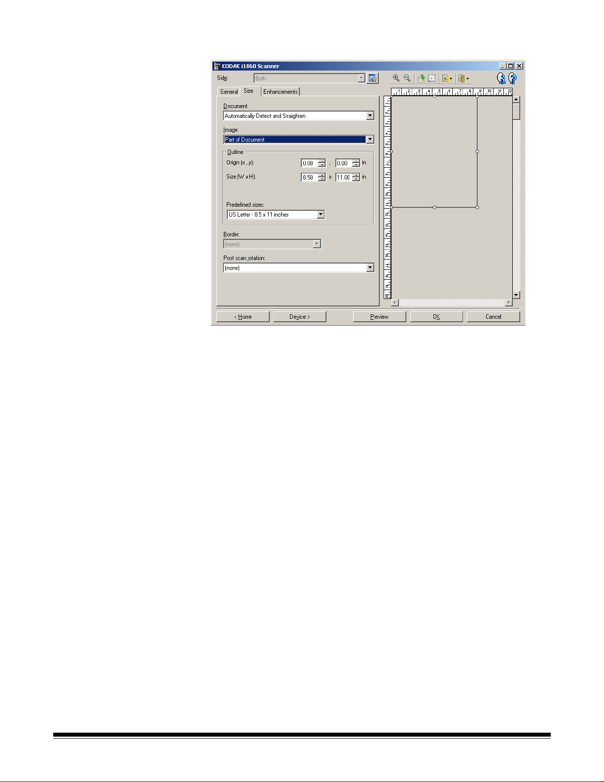
Image Settings - Size tab The Size tab provides the following options.
Document — allows you to select how the scanner will detect your
document as it is being fed through the scanner.
• Automatically Detect and Straighten: the scanner will
automatically find each document (regardless of size) and straighten
any document that may have been fed crooked.
• Automatically Detect: the scanner will automatically find each
document (regardless of size). If a document is fed crooked, it will not
be straightened.
• Manually Detect: the scanner will return an image based on the area
you specify with the Outline options. It is suggested that you only use
this option for scan jobs that contain same-sized documents.
Image — allows you to select which part of the document you want for
your electronic image.
• Entire document: if you select Document: Automatically Detect
and Straighten, Document: Automatically Detect or Document:
Manually Detect, returns the entire document.
• Part of the document: if you select Document: Automatically
Detect and Straighten, returns the portion of the document which
you specify with the Outline options.
3-12 A-61580 November 2007
Page 41

Outline — allows you to select the location and size to use for creating
your electronic image. The preview area will show the outline.
• Origin (x, y):
- if you select Document: Automatically Detect and Straighten,
(x) is the distance from the left edge of the document and (y) is
the distance from the top edge of the document.
- if you select Document: Manually Select, (x) is the distance
from the left edge of the scanner’s paper path and (y) is the
distance from the first portion of the document detected by the
scanner.
• Size (w, h): if you select Document: Automatically Detect and
Straighten or Document: Manually Select, this is the width and
height of the electronic image.
NOTE: The electronic image may be shorter than you specified if the
outline goes beyond the end of the scanned document.
• Predefined sizes: provides a list of commonly used paper sizes.
Selecting an item in this list will automatically set the size of the
outline to that paper’s size. Custom will be displayed when the
outline size does not match any sizes in this list.
NOTE: You can also adjust the outline displayed in the preview area
using your mouse.
Border — allows you to select what action to perform on the edges of
your electronic image.
• (none)
• Add: includes up to approximately 0.1 inches of border around all of
the image edges.
NOTE: This option is only available for Document: Automatically
Detect and Straighten or Document Manually Select.
• Remove: produces an image that contains just the document by
eliminating any residual border. Residual border can be caused by
variations in a document edge; for example, when a document is not
a perfect rectangle and/or was fed crooked.
NOTES:
- While this option will not remove large amounts of residual
border, there is a possibility that a small amount of the document
will be lost.
- This option is only available when both Document:
Automatically Detect and Straighten and Image: Entire
Document are selected.
A-61580 November 2007 3-13
Page 42
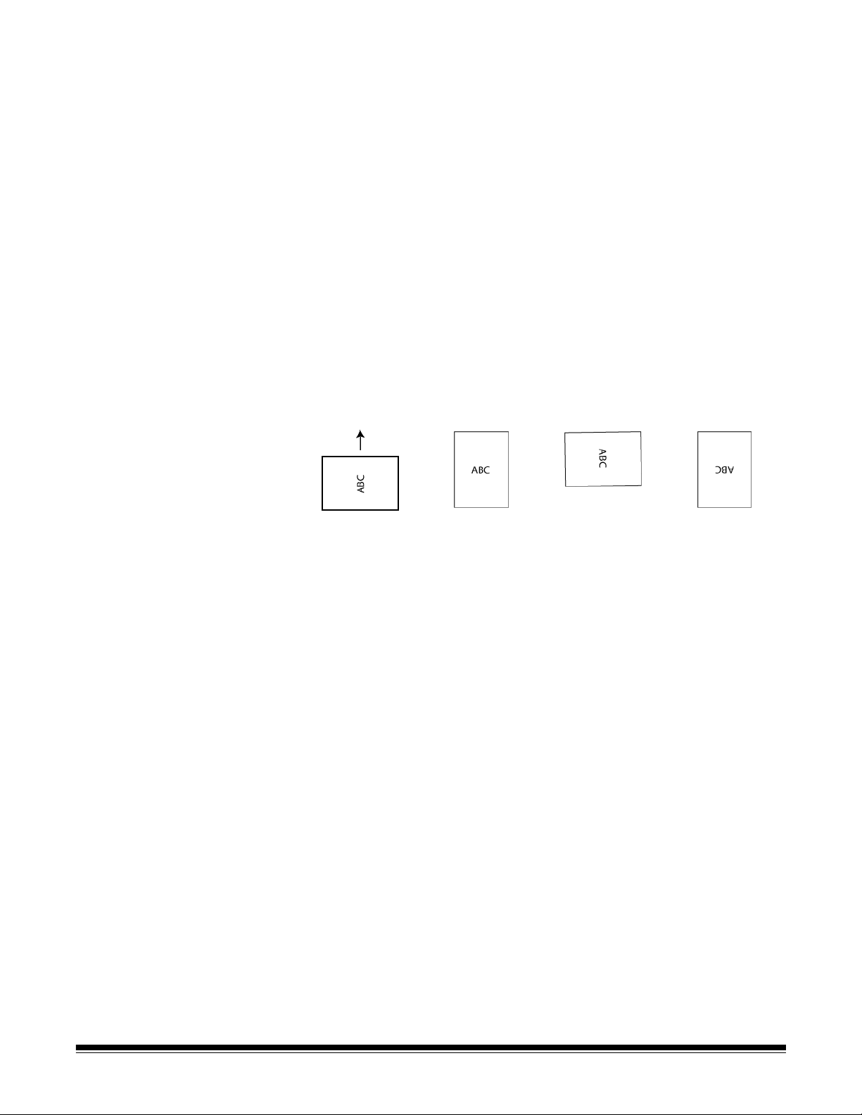
Post scan rotation — allows you to select any rotation to be applied to
the electronic image after it has been scanned.
• (none)
• Automatic — the scanner will analyze each document to determine
how it was fed and will rotate the image to the proper orientation.
NOTES:
- There must be a sufficient amount of text on the page for this
option to work properly.
- This option is designed to work best with Latin-based characters
(e.g., English, Dutch, French, German, Italian, Spanish).
• 90, 180, 270 degrees: the amount of rotation.
The following example shows how these settings effect a document
that was fed landscape.
Landscape
Feed Orientation
90 degrees 180 degrees 270 degrees
3-14 A-61580 November 2007
Page 43
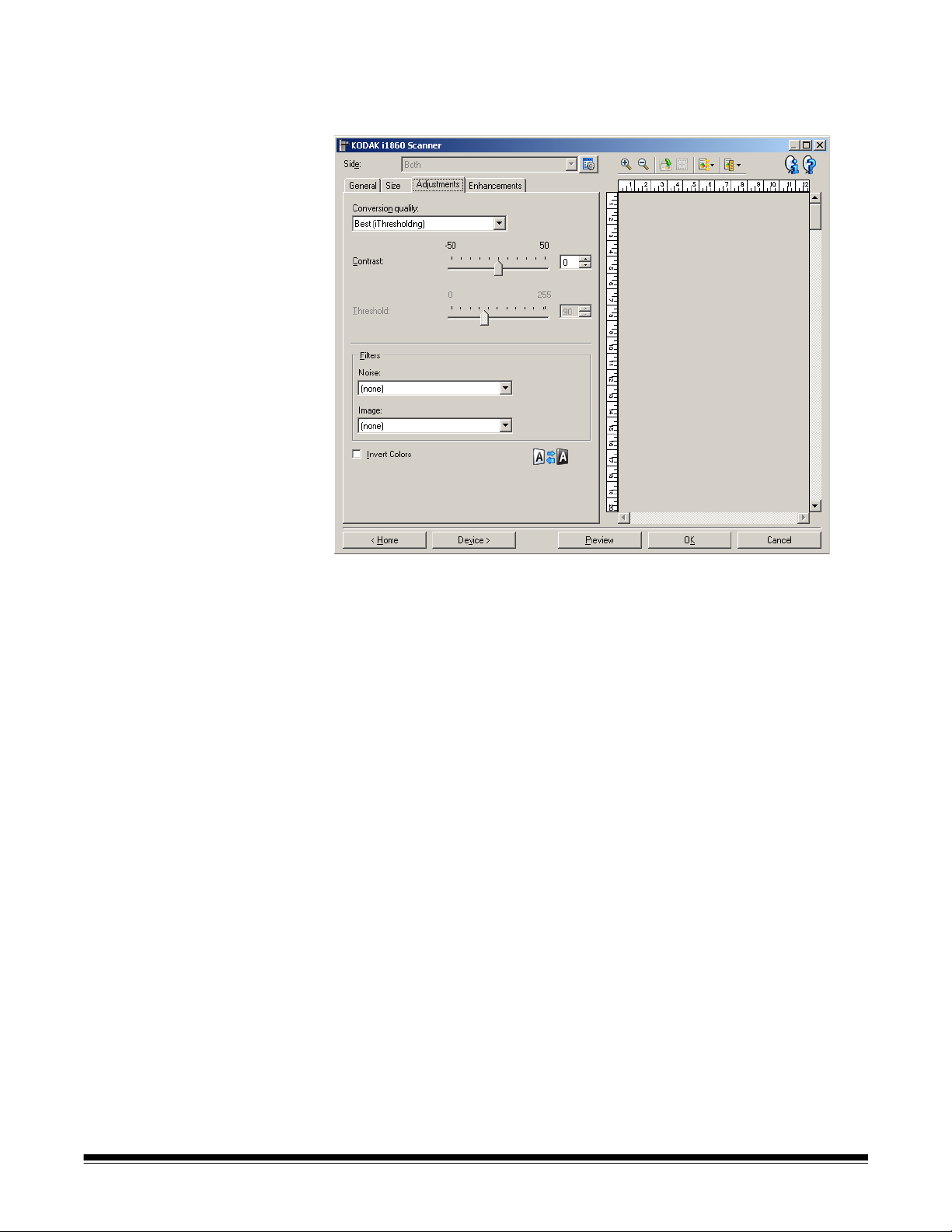
Image Settings Adjustments tab
The options available on the Adjustments tab depend on the Scan as
selection on the General tab. The following options are based on a
Scan as selection of Black and White.
Conversion quality — these settings effect how the scanner analyzes
a grayscale version of the document which is used to produce the black
and white electronic image.
• Best (iThresholding): the scanner analyzes each document to
determine the optimal settings to produce the highest quality image.
This option allows scanning of mixed documents with varying quality
(i.e., faint text, shaded backgrounds, color backgrounds) and when
scanning with consistent document sets.
• Normal (ATP): allows you to determine the optimal settings to
produce the desired image quality. This option works best when
scanning with consistent document sets. You may also want to use
this option if you have difficult documents such that you cannot find a
Contrast setting for Best that produces the desired quality.
• Draft (Fixed): allows you to select the grayscale threshold used to
determine if a pixel is black or white. This option works best for high
contrast documents.
Contrast — allows you to make an image sharper or softer. Decreasing
this setting will make the image softer and reduce noise in the image.
Increasing this setting will make the image clearer and make light
information more visible. The options range from-50 to 50. The default
is 0.
NOTE: This is only available for Conversion quality: Best and
Conversion quality: Normal.
A-61580 November 2007 3-15
Page 44

Threshold — aids in controlling the level at which a pixel is considered
black or white.
• Decreasing this setting will make the image appear lighter, and can
be used to subdue background noise.
• Increasing this setting will make the image appear darker, and can be
used to help pick up light information.
The options range from 0 to 255. The default is 90.
NOTE: This is only available for Conversion quality: Normal and
Conversion quality: Draft.
Filters
• Noise
- (none)
- Lone Pixel: reduces random noise by converting a single black
pixel to white when it is completely surrounded by white pixels or
by converting a single white pixel to black when it is completely
surrounded by black pixels.
- Majority Rule: sets each pixel based on its surrounding pixels.
The pixel will become white if the majority of the surrounding
pixels are white and visa versa.
No Noise Filter Used Lone Pixel
•Image
- (none)
- Halftone Removal: enhances dot matrix text and images made
with halftone screens (e.g. newspaper photographs).
Invert Colors — allows you to select how the black pixels will be stored
in the image. By default the black pixels are stored as black and the
white pixels are stored as white. Turn this option on if you want the
black pixels stored as white and the white pixels stored as black.
3-16 A-61580 November 2007
Page 45

Image Settings Enhancements tab
The options available on the Enhancements tab depend on the Scan as
selection on the General tab.
Blank Image Detection — allows you to configure the scanner to
eliminate blank images.
• On: turns Blank Image Detection on and makes the rest of the Blank
Image Detection options available.
• Delete if file size is less than: allows you to select the minimum
image size that the scanner will consider to be non-blank. Any image
that is less than this value will be considered blank and will not be
given to the scanning application. The values range from 1 to 1000
KB (1 KB equals 1024 bytes).
Color Dropout — used to eliminate a form's background so that only
the entered data is included in the electronic image (i.e. remove the
form's lines and boxes). For black and white images, these settings
effect the grayscale version of the document which the scanner
analyzes to produce that electronic image.
• Color: select the desired dropout color. Options are: (none), Red,
Green, and Blue.
• Filter Threshold: allows you to adjust how the scanner identifies the
color to be dropped. The values range from 0 to 255. Default: 175.
• Background: allows you to select the grayscale value to replace the
dropped color with. It is suggested that this value be higher than the
Threshold value selected on the Adjustments tab in order for the
dropped color to appear to be part of the background. The values
range from 0 to 255. Default: 245.
NOTE: The Color Dropout options are only available when the Scan as
selection is Black and White.
A-61580 November 2007 3-17
Page 46
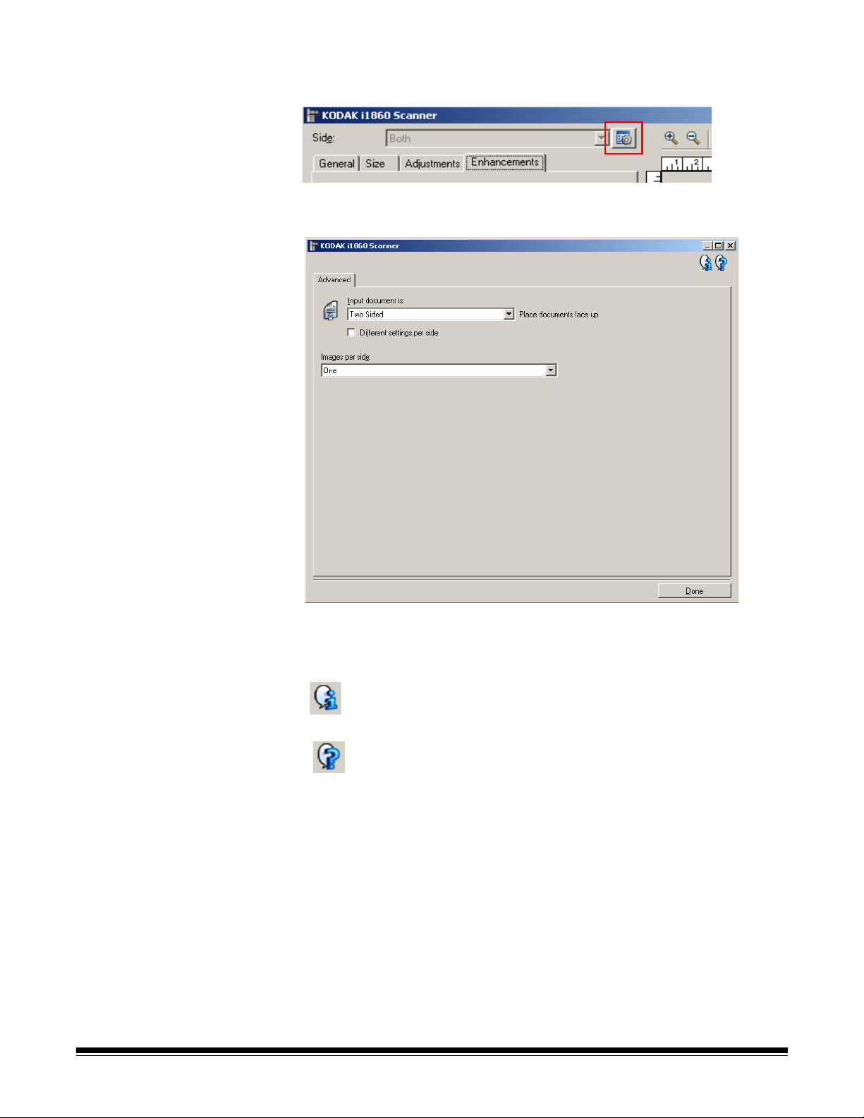
Advanced Image
Setup
The Advanced Image Setup is accessed via the icon located next to the
Side option at the top of the Image Settings window.
When you select the Advanced Image Setup icon, the Advanced tab
will be displayed.
Done — returns you to the Image Settings window.
Information icons
About: displays the scanner’s version and copyright information.
Help: displays help information for the window currently being
displayed.
3-18 A-61580 November 2007
Page 47
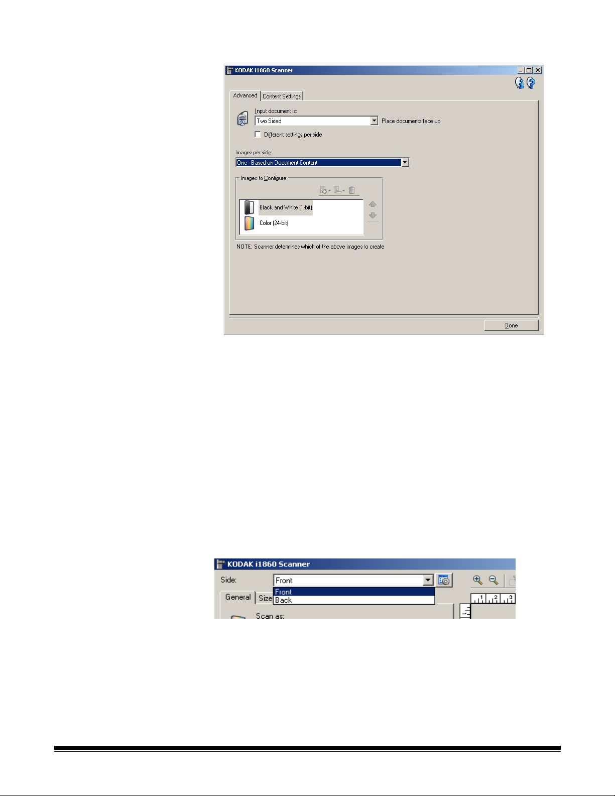
Advanced tab
Input document is — select Two Sided, One Sided - Front, or One
Sided - Back depending on what side(s) you want to configure.
NOTE: The Two Sided and One Sided - Back options are only available
for duplex scanner models.
Different settings per side — by default, the settings you select in the
TWAIN Datasource apply to both sides of the image. Turn this option on
if you want you to select different image processing settings for each
side of the document you are scanning. For example, if you want the
front side to be color and the rear side to be black and white, first make
sure that you have selected the Two Sided option of Input document is,
then turn on Different settings per side.
Once you have done this, the Side option on the Image Settings
window will no longer be grayed out and you can select different
settings for each side.
Now that you have turned on Different settings per side, your
selections will apply only to the front side of the document you are
scanning. After you have made your selections for the front side, use
the Side option to select the back side and then make the settings you
want to apply to the back.
NOTE: The Different settings per side option is only available for duplex
scanner models.
A-61580 November 2007 3-19
Page 48

Images per side — indicates how many images the scanner will create
for a side, based on your imaging selections.
• One: indicates you want the scanner to create one image.
• One - Based on Document Content: indicates you want the
scanner to automatically detect if the document is color/grayscale or
black and white.
• One - Based on Toggle Patch: indicates you want to tell the
scanner, via a toggle patch document, if the document is color/
grayscale or black and white.
• Multiple: indicates you want the scanner to create more than one
image.
NOTE: If you select One - based on Document Content from the
Images per side option, the Content Settings tab will be
displayed.
Images to Configure — indicates which electronic images you need to
configure.
NOTE: This is only available if you select anything other than One from
the Images per side option.
3-20 A-61580 November 2007
Page 49

Refer the examples later in this chapter for procedures on how to
configure advanced options.
When available, use the up and down arrows to select the order the
images will be delivered by the scanner to the scanning application.
Toolbar buttons
Add: adds an image type to the bottom of the configuration list.
Change: allows you to change the currently selected image
type.
Delete: removes the selected image type.
Done — returns you to the Image Settings window.
A-61580 November 2007 3-21
Page 50

Content Settings tab The options on the Content Settings tab can be used for either one- or
two-sided jobs.
Side — determines which side the Sensitivity settings are applied to.
This option is only available if Different settings per side is turned on
from the Advanced tab.
Sensitivity
• Low: documents requiring only a small amount of color to be saved
as color/grayscale images. Used for capturing documents that are
primarily black text with small logos, or contain small amounts of
highlighted text or small colorful photos.
• Medium: documents requiring more color, as compared with the Low
option, before they are saved as color/grayscale images.
• High: documents requiring more color, as compared with the Medium
option, before they will be saved as color/grayscale images. Used for
distinguishing documents containing medium- to large-size colorful
photos from plain black text. Photos with neutral colors may require
adjustments to the Color threshold or Color amount values in order to
be captured correctly.
3-22 A-61580 November 2007
Page 51

• Custom: allows you to manually adjust the Color amount and/or
Color threshold.
NOTE: When setting Sensitivity values, it is suggested that you start
with the Medium option and scan a typical job set. If too
many documents were returned as color/grayscale vs. black
and white, then change to the High option and re-run the job.
If too few documents were returned as color/grayscale vs.
black and white, then change to the Low option and re-run
the job. If none of these options provide the desired result,
select Custom to manually adjust Color amount and/or Color
threshold. Custom also allows access to the Learn mode
which provides a method for the scanner to analyze
documents and recommend settings.
Color amount — the amount of color that needs to be present in a
document before it will be saved as color/grayscale. As the value of
Color amount increases, more color pixels are required. The options
range from 1 to 200.
Color threshold — the color threshold or saturation (i.e., pale blue vs.
dark blue) at which a given color will be included in the color amount
calculation. A higher value indicates that a more intense color is
required. The options range from 0 to 100.
Learn — allows you to calculate your settings based on representative
color documents scanned. Before clicking Learn, place at least 5
representative color documents in the input elevator. The documents
will be scanned and analyzed to determine the recommended color
amount.
NOTE: The Color amount and Color threshold sliders will be updated
automatically. If these values do not provide the desired results
with your job set, you may need to adjust the Color threshold
manually.
A-61580 November 2007 3-23
Page 52

Creating color/grayscale
or black and white
images based on the
content of your
documents
In this example, let’s assume you want to configure a scan session that
has a mix of color and black and white documents with information on
both sides. In addition, you want the scanner to detect whether the
page is color or not, and then output either a color or a black and white
image based on that.
1. Select a Setting Shortcut from the main Kodak Scanner window
that closely describes your desired output.
2. Select Settings to display the Image Settings window.
3. Select the Advanced Image Setup icon on the Image Settings
window to display the Advanced tab.
4. Select Input document is: Two Sided.
5. Select Images per side: One - based on document content.
NOTE: The Images to Configure area will now be displayed on the
Advanced tab and contain a color image item and a black
and white image item. The Content Settings tab will also be
displayed.
6. If you want a grayscale image instead of a color image, when
enough color is detected in the document:
• make sure Color (24-bit) is selected
• select Change to display a list of options
• select Grayscale
7. Go to the Content Settings tab.
8. Select a Sensitivity option.
3-24 A-61580 November 2007
Page 53

9. Select Done to return to the Image Settings window.
NOTE: You will notice that the Side option now has two entries:
Both: Color (24-bit) and Both: Black and White (1-bit).
10.Select Sides: Both: Color (24-bit).
Make any other adjustments to the color image settings on the rest
of the tabs on the Image Settings window.
11. Selec t Sides: Both: Black and White (1-bit).
Make any other adjustments to the black and white image settings
on the rest of the tabs on the Image Settings window.
12.When finished, select Home to return to the main Kodak Scanner
window and then select Save to save your selections to the
shortcut.
A-61580 November 2007 3-25
Page 54

Creating multiple images
for each side of a
document
In this example, let’s assume you want to configure a scan session that
has documents with information on both sides and you want the
scanner to produce both a color and a black and white image for each
side of each document.
1. Select a Setting Shortcut from the main Kodak Scanner window
that closely describes your desired output.
2. Select Settings to display the Image Settings window.
3. Select the Advanced Image Setup icon on the Image Settings
window to display the Advanced tab.
4. Select Input document is: Two Sided.
5. Select Images per side: Multiple.
NOTE: The Images to Configure area will now be displayed on the
Advanced tab and will contain a color image item and a
black and white image item.
6. If you want a grayscale image instead of a color image, when
enough color is detected in the document:
• make sure Color (24-bit) is selected
• select Change to display a list of options
• select Grayscale
7. By default the scanner will produce the color/grayscale image first
and deliver it to the scanning application, then it will produce and
deliver the black and white image. If you want the black and white
image to be produced and delivered first:
• make sure Black and White (1-bit) is selected
• select Move up to place the black and white image first in the list
3-26 A-61580 November 2007
Page 55

8. Select Done to return to the Image Settings window.
NOTE: You will notice that the Side option now has two entries:
Both: Color (24-bit) and Both: Black and White (1-bit).
9. Select Sides: Both: Color (24-bit).
Make any other adjustments to the color image settings on the rest
of the tabs on the Image Settings window.
10.Select Sides: Both: Black and White (1-bit).
Make any other adjustments to the black and white image settings
on the rest of the tabs on the Image Settings window.
11. When finished, select Home to return to the main Kodak Scanner
window and then select Save to save your selections to the
shortcut.
A-61580 November 2007 3-27
Page 56

Creating different
settings for each side of
a document
In this example, let’s assume you want to configure a two-sided
document stream of business documents that have color on the front of
the document but the rear side is fine in black and white.
1. If you are not already on the Advanced tab:
• Select a Setting Shortcut from the main Kodak Scanner window
that closely describes your desired output.
•Select Settings to display the Image Settings window.
•Select Advanced Image Setup icon on the Image Settings
window to display the Advanced tab.
2. Select Input document is: Two Sided.
3. Turn on the Different settings per side option.
4. Select Images per side: One.
5. Select Done to return to the Image Settings window.
NOTE: You will notice that the Side option now has two entries:
Front and Back.
6. Select Sides: Front.
7. Select Color (24-bit) for the Scan as option on the General tab.
Make any other adjustments to the front side settings on the rest of
the tabs on the Image Settings window.
8. Select Sides: Back.
9. Select Black and White (1-bit) for the Scan as option on the
General tab.
Make any other adjustments to the back side settings on the rest of
the tabs on the Image Settings window.
10.When finished, select Home to return to the main Kodak Scanner
window and then select Save to save your selections to the
shortcut.
NOTE: If you selected any option other than Images per side: One in
Step 4, two Images to Configure options groups would become
available. You can then individually setup the images that will be
produced for each side of the document.
3-28 A-61580 November 2007
Page 57

The Device Settings
window
From this window you can set all scanner-specific options, as well as
diagnostics, by using the available tabs. The values used in Device
Settings are saved in the selected Setting Shortcut. The Device
Settings window includes the following tabs: General, Printer, Multifeed,
Image Address, Batch, Patch, and OCP.
Home — returns you to the main Kodak Scanner window.
Image — displays the Image Settings window.
Preview — initiates a scan and then displays the Image Settings
window with the scanned image placed in the preview area. The image
displayed is a sample based on your current shortcut setting.
OK/Scan — when selected, you will be prompted to save any unsaved
changes.
NOTE: If this button is OK, any unsaved changes will remain in affect
for the current scan session.
Cancel — closes the main Kodak Scanner window without saving any
changes.
Information icons
About: displays the scanner’s version and copyright information.
Help: displays help information for the window currently being
displayed.
A-61580 November 2007 3-29
Page 58
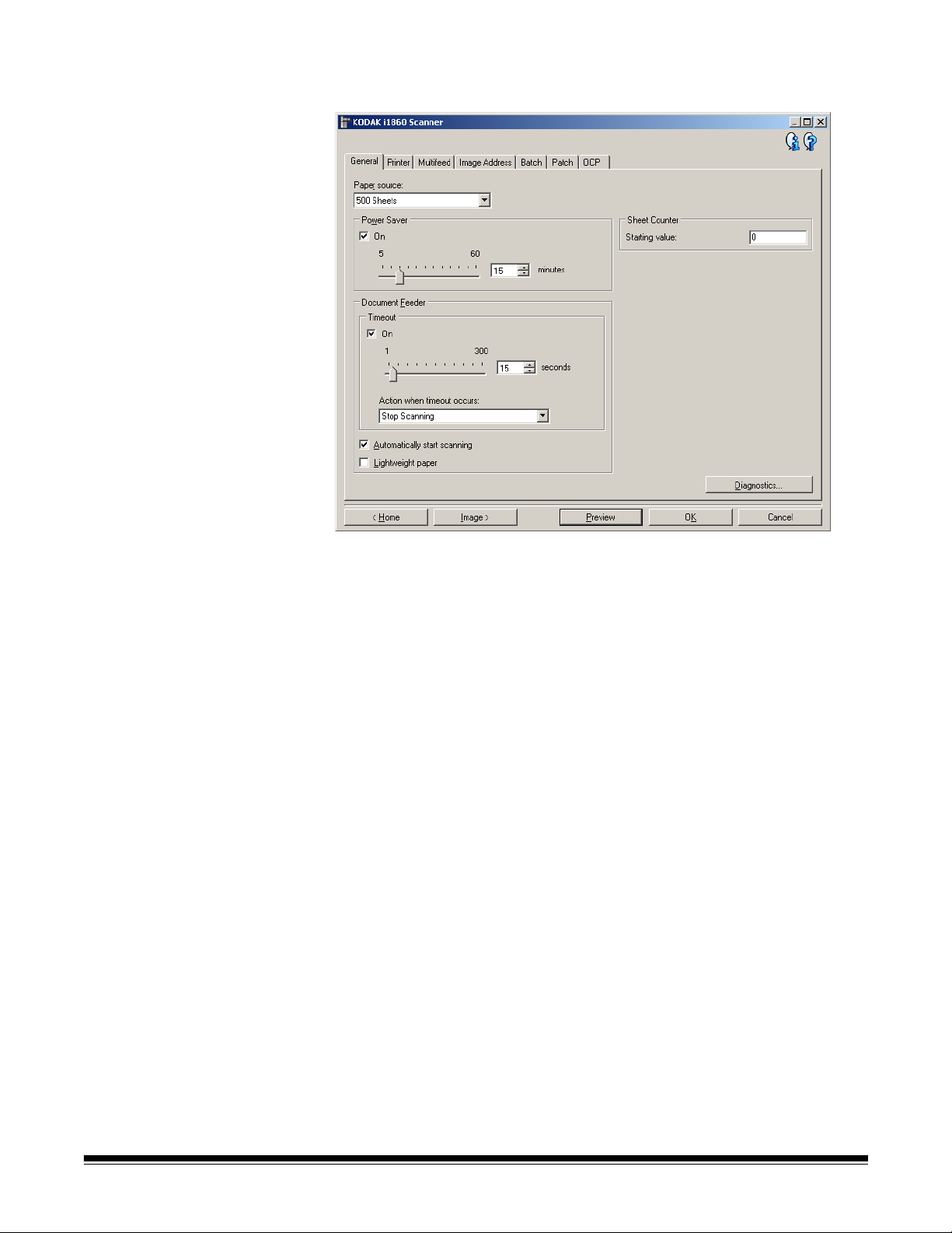
Device - General tab The General tab allows you to set scanner-specific options and provide
access to scanner diagnostics.
Paper source
• Document Feeder: the input elevator is in its highest position. This
selection is recommended when you are scanning 25 sheets or less.
• 100 Sheets: this selection is recommended when you are scanning
between 25 and 100 sheets.
• 250 Sheets: this selection is recommended when you are scanning
between 100 and 250 sheets.
• 500 Sheets: this selection is recommended when you are scanning
between 250 and 500 sheets.
Power Saver — allows you to set the amount of time the scanner has
to be inactive before going into power saver mode. You can turn this
option off or set a time from 5 to 60 minutes.
Document Feeder
• Timeout: allows you to select the amount of time the scanner will
wait once the last document enters the feeder before the timeout
occurs. You can turn this option off or set a time from 1 to 300
seconds.
3-30 A-61580 November 2007
Page 59

• Action when timeout occurs: indicates the action that will be taken
when the document feeder timeout has been reached.
- Stop Scanning: scanning will stop and control will return to the
scanning application (i.e. ends the job).
- Pause Scanning: scanning will stop but the scanning application
will be waiting for additional images (i.e. stops the feeder).
Scanning may be resumed by touching Resume on the
touchscreen. Scanning may be stopped by touching End Job on
the touchscreen or via the scanning application.
• Automatically start scanning: if selected, the scanner will wait for
up to 10 seconds for documents to be placed in the input elevator
before scanning will begin. In addition, once the input elevator has
been emptied, the scanner will automatically resume scanning when
paper is placed in the input elevator. The scanner will wait the
amount of time specified by the document feeder timeout.
• Lightweight paper: improves output stacking when scanning
lightweight paper. When selected, the scanner will increase the gap
between documents in order to allow each document to settle in the
output tray before the next document gets to the output tray.
NOTE: Using this option will decrease overall throughput.
Sheet Counter — enter a value that will be used to assign the
document count for the next document entering the scanner. This is
incremented sequentially by the scanner and is returned in the image
header.
Diagnostics — displays the Diagnostics tab.
A-61580 November 2007 3-31
Page 60

Device - Printer tab The Enhanced Printer provides a vertical print capability and supports
alphanumeric characters, date, image address, time, document count
and custom messages. All print information is captured in the image
header of each document.
On — turns printing on and makes the rest of the options on this tab
available.
Level to configure — choose the level of the document that you want
the specified print string to be printed on. For example, if you use three
level image addressing, you can print the date on your level 3
document, nothing on level 2 and document count on level 1. Image
addressing must be enabled for this option to be available.
• All levels match: turn this option on if you want all the print strings to
be the same for all levels.
NOTES:
- This option is only available when the scanner is in Image
Address mode.
- Image Address mode is not available for all models.
3-32 A-61580 November 2007
Page 61

Template: Format — allows you to define your print string. The
maximum amount of characters for the print string is 40 characters
(including spaces).
Add — displays a list of items you can add to
your print string. When you select an item, that
item will appear at the end of the Format list.
Change — allows you to change the currently
selected item in the Format list with one of the
items from the list that is displayed.
Delete — allows you to remove the currently
selected item from the Format list.
As you build your print string, only items that will fit in the 40-character
limit will be available from the Add and Change lists.
Items — when an item is selected, any associated options will be
displayed to the right of the Format list.
• Counter: this is the document count for the scan session. This value
is incremented sequentially by the scanner and returned in the image
header.
- Starting value: allows you to set the document count for the next
document that will be scanned.
- Field width: allows you to configure the width of the counter from
1 - 9. However, if for example, you only have 6 characters left in
the print string, then the field width would be limited to 6.
- Leading zeroes: allows you to configure the format of the
counter when the width of the value is less than the field width
(the examples indicate a field width of 3 and the counter at 4).
• Display: "004"
• Do Not Display: "4"
• Display As Spaces: " 4"
A-61580 November 2007 3-33
Page 62

•Date
- Format:
• MMDDYYYY
• DDMMYYYY
• YYYYMMDD
•DDD (Julian)
• YYYYDDD (Julian)
- Separator: (the examples indicate a format of YYYYMMDD)
•None
• Slash: 2007/08/24
• Hyphen: 2007-08-24
• Period: 2007.08.24
• Space: 2007 08 24
- Specific date: allows you to select a specific time if you do not
want to use the current date within the scanner.
• Time: the format is HH:MM.
- Specific time: allows you to select a specific time if you do not
want to use the current time within the scanner.
• Space: adds a space.
• Image Address: Fixed and Image Address: Levels: these are
defined on the Image Address tab. Only the levels currently defined
will be available.
• Message: allows you to specify custom text to be included in your
print string. A maximum of 20 characters is allowed. You can have up
to 6 unique messages per messages.
To view the Japanese characters correctly you must get the MS
Gothic font set by installing the Microsoft Global IME 5.01 for
Japanese - with Language Pack, English Language Version which
can be found at http://www.microsoft.com/msdownload/iebuild/
ime5_win32/en/ime5_win32.htm.
Template: Example — shows a sample of what the print string will
look like. As you select items in the Format list, the corresponding
portion within the example will be highlighted.
Font — you can select what orientation you want your information to be
printed.
• Format:
- Normal: prints a single vertical line of characters (one character
per horizontal line).
- Block: prints a block of characters (6 characters per horizontal
line).
NOTE: This option is only available when the High-Resolution Printer
Accessory is installed.
• Style: available character styles: Normal and Bold.
3-34 A-61580 November 2007
Page 63

• Orientation: while the characters are printed vertically (starting at the
lead edge of the document) this allows you to select the orientation of
the print string. Available options are: 0, 90, 180, 270.
Feed Direction 0 90 180 270
Offset from lead edge — select a value from 0.35 to 33.5 inches to
determine how far the printed information will appear from the leading
edge of the document.
NOTES:
• Printing automatically stops 6.3 mm (1/4-inch) from the trailing edge
of the document even if the information has not been completely
printed.
• The horizontal print position is set manually on the scanner. See
Chapter 4, The Enhanced Printer and Patch Readers, in the User’s
Guide for information on changing the horizontal print position.
A-61580 November 2007 3-35
Page 64

Device - Multifeed tab Multifeed detection aids in document processing by detecting
documents that may go through the feeder overlapped. Multifeeds can
happen due to stapled documents, adhesives on documents, or
electrostatically charged documents.
Ultrasonic detection
Sensitivity — controls how aggressively the scanner will work to
determine if more than one document is fed into the scanner. Multifeeds
are triggered by detecting air gaps between documents. This allows
multifeed detection to be used with job sets containing documents with
mixed thicknesses.
•(none)
• Low: least aggressive setting and is less likely to detect labels, poor
quality, thick or wrinkled documents as multi-fed documents.
• Medium: use if your job set has varying document thicknesses or
labels attached to the document. Depending on the label material,
most documents with labels should not be detected as a multi-fed
document.
• High: most aggressive setting. This is a good setting to use if all
documents are similar in thickness no greater than 20-lb. bond paper.
NOTE: Regardless of the setting, “sticky” notes will be detected as
multi-fed documents.
3-36 A-61580 November 2007
Page 65

Sensors — three sensors cover the width of the paper path. In order for
multi-fed documents to be detected correctly, they must pass under one
of these sensors.
• Left, Middle, Right: this allows you to select which sensor(s) you
want turned on. For example, if you know that the left side of the
document has a “sticky” note on it, you can turn off the left sensor.
Length Detection — allows you to select the maximum length of the
documents in your job set. If the scanner detects a document of that
length or longer, it will determine that a multifeed has occurred. You can
turn this option off, or set a length of up to 34.5 inches.
Action When Detected — select what action you want the scanner to
take when a multifeed is detected. With all options, the scanner will
beep (if the scanner volume is on) and the condition will be logged in
the scanner.
• Stop Scanning: scanning will stop and control will return to the
scanning application (i.e., ends the job). Verify that the paper path
has been cleared and restart the scan session from the scanning
application.
• Continue Scanning: the scanner will continue to scan.
• Pause Scanning: scanning will stop but the scanning application will
be waiting for additional images (i.e., stops the feeder). Scanning
may be resumed by touching Resume on the touchscreen. Scanning
may be stopped by touching End Job on the touchscreen or via the
scanning application.
Play sound on PC — turn this option on if you want the PC to make a
sound when a multifeed is detected. You can click the Browse button to
select the desired .wav file.
NOTE: The sound on the PC may not occur at the exact time the
multifeed is detected by the scanner.
A-61580 November 2007 3-37
Page 66

Device - Image Address
tab
Image addressing is used for document tracking, batch control and
image management. The Image Address tab allows you to set an
image address starting point. The scanner will increment the image
address based on how you set up the image address rules on this tab.
NOTES:
• This tab is only available when the scanner is in Image Address
mode.
Current value — displays the scanner’s current image address. This
value is used by the scanner as the next image address which is
assigned to the next document scanned.
Starting Address — allows you to enter a starting image address
which overrides the Current value. You can enter a value for each
available field, up to the maximum allowed characters for that field. The
number of available fields, the field types, and the number of characters
allowed per field are based on the Template settings for Format and
Field width (see below).
Templa t e
• Format: allows you to select the format of the image address. The
examples below indicate the available fields.
- Fixed: Fixed
- Level 3: Fixed.Level 3.Level 2.Level 1
- Level 2: Fixed.Level 2.Level 1
- Level 1: Fixed.Level 1
- Level 3 Offset: Fixed.Level 3.Level 2
- Level 2 Offset: Fixed.Level 2
3-38 A-61580 November 2007
Page 67

NOTES:
• When you make a Format selection, the Field width and Next Level
settings will automatically be set to the defaults for that format.
• If you made a change to the Field width or Next Level settings, the
Format will be appended with the text <changed>, and the name will
be displayed in italics (e.g., *Level 3 <changed>).
• Reset: allows you to undo any changes that have been made to
the format. This is only available when you have modified the format
(e.g., are in italics and appended with <changed>).
• Field width — allows you to configure the width of each field from
1 - 9. However, the sum total of all the field widths cannot exceed 27,
therefore, the field width may be limited to a value less than 9.
• Next Level: the level to assign to the next document.
- After Level 3: allows you to select what level to assign to the
document that follows a level 3 document.
- After Level 2: allows you to select what level to assign to the
document that follows a level 2 document.
- After Level 1: allows you to select what level to assign to the
document that follows a level 1 document.
The options for all three of the above are: Level 1, Level 2, and
Level 3. However, the available options are based on the image
address format. For example, if the Format does not have Level 3
as one its fields, then Level 3 will not available.
NOTE: While scanning, a document can also be assigned a level by
inserting a patch sheet (when turned on via the Patch tab) or
selecting a level field on the scanner's touchscreen. For more
information refer to the User's Guide which is included with
your scanner.
Leading zeros allows you to configure the format of the level
address fields when the width of the value is less than the field width
(the examples indicate a field width of 3 and the image address at
A.3.2.1).
• Display (e.g., A.003.002.001)
• Do Not Display (e.g., A.3.2.1)
• Display as Spaces (e.g., A. 3. 2. 1)
A-61580 November 2007 3-39
Page 68

Device - Batch tab Batching is the operation of counting pages or documents.
NOTE: This tab is only available when the scanner is in Image Address
mode.
On — turns batching on and makes the rest of the options on this tab
available.
Level to count — sets the level to count.
Level 2, and Level 3.
NOTE: The level you want to count must exist in the image address
template as defined on the Image Address tab.
How Many To Count — defines the number of documents to be
counted prior to performing the action to take when the count has been
reached.
When Count Reached
• Next Level: defines the level for the next document after the count is
reached. Options are: (none), Level 1, Level 2, and Level 3.
NOTE: The level you want to count must exist in the image address
template as defined on the Image Address tab.
The options are Level 1,
3-40 A-61580 November 2007
Page 69

• Action to take: defines the action to be taken after processing the
last document in the batch.
- Pause Scanning: scanning will stop but the scanning application
will be waiting for additional images (i.e. stops the feeder).
Scanning may be resumed by touching Resume on the
touchscreen. Scanning may be stopped by touching End Job on
the touchscreen or via the scanning application.
- Stop Scanning: scanning will stop and control will return to the
scanning application (i.e. ends the job). Restart the scan session
from the scanning application.
- Continue Scanning and Restart Count: the scanner will
continue to scan and automatically start a new batch by resetting
How Many to Count.
NOTE: You can also end a batch before the How Many To Count is
reached by using the touchscreen on the scanner. This can be
accomplished by setting up a function key via the OCP tab to be
End Batch.
A-61580 November 2007 3-41
Page 70

Device - Patch tab The Patch tab provides choices of what patch type to recognize. One or
more patches can be selected at a time. The type of patch recognized
is returned in the image header.
See the Kodak publication A-61599, Patch Code Information for Kodak
Document Scanners for complete information.
Patch Confirmation Tone — the confirmation tone may be used to
signal that a patch has been recognized by the scanner. The default is
no confirmation tone.
Recognize — select which patch type(s) to recognize.
• Level 2: assigns a Level 2 to the current document (whether it is your
document with a patch on it or a Level 2 patch sheet)
• Level 3: assigns a Level 3 to the current document (whether it is your
document with a patch on it or a Level 3 patch sheet)
• Transfer: assigns a level to the next document (after the Transfer
patch sheet).
- None: select this if you do not want to recognize transfer patches.
- As Level 2
- As Level 3
NOTE: The Transfer patch will be treated as Level 0.
.
.
3-42 A-61580 November 2007
Page 71

Feature
• Patch Types 1, 4 and 6 these patch types can be used by the
scanning application for post-scan image control (they are not used
for image addressing). For example, use these patch types for
workflow control or changing between black and white and color/
grayscale imaging.
NOTE: This option is only available when the scanner is in Image
Address mode.
Use Heads — select which patch heads/readers you would like to use.
Each patch head/reader can be turned on and off independently. The
default is for all patch heads/readers to be turned on.
NOTE: This option is only available when the scanner is in Image
Address mode.
A-61580 November 2007 3-43
Page 72

Device - OCP tab The OCP tab is used to setup options on the scanner’s Operator
Control Panel (i.e., touchscreen).
Function Keys — available functions for each key are:
•(none)
• Stop Scanning: scanning will stop and control will return to the
scanning application (i.e., ends the job). Restart the scan session
from the scanning application.
• End Batch: start a new batch by resetting the batch count (i.e. How
Many to Count) and continue to scan.
• Omit Multifeed: turn off multifeed detection only on the next
document that is fed.
• Omit Print: turn off printing only on the next document that is fed.
• Omit Patch: turn off patch recognition only on the next document that
is fed.
• Lower Elevator: moves the elevator to the lowest position.
NOTE: The End Batch and Omit Patch options are only available
when the scanner is in Image Address mode.
3-44 A-61580 November 2007
Page 73

Creating a new
Setting Shortcut
Setting Shortcuts are separately named and contain all scanner
settings required to do a certain scanning job. By default, the i1800
Scanner comes with predefined Setting Shortcuts for the most common
scanner tasks. You can use these default Setting Shortcuts or use them
as a template to create your own Setting Shortcut.
You cannot modify the default Setting Shortcuts.
The procedures that follow describe how to configure a customized
Setting Shortcut. Complete descriptions of the options on the main
Kodak Scanner window and tabs are found in the section entitled, “The
main Kodak Scanner window”.
From the main Kodak Scanner window:
1. From the main Kodak Scanner window, select a Setting Shortcut
from the list. It is recommended that you select a shortcut that beset
describes the desired image output.
2. Determine if you want to capture an electronic image of the front of
your document, back of your document or both sides of your
document and make the selection from the Input Document is field.
A-61580 November 2007 3-45
Page 74
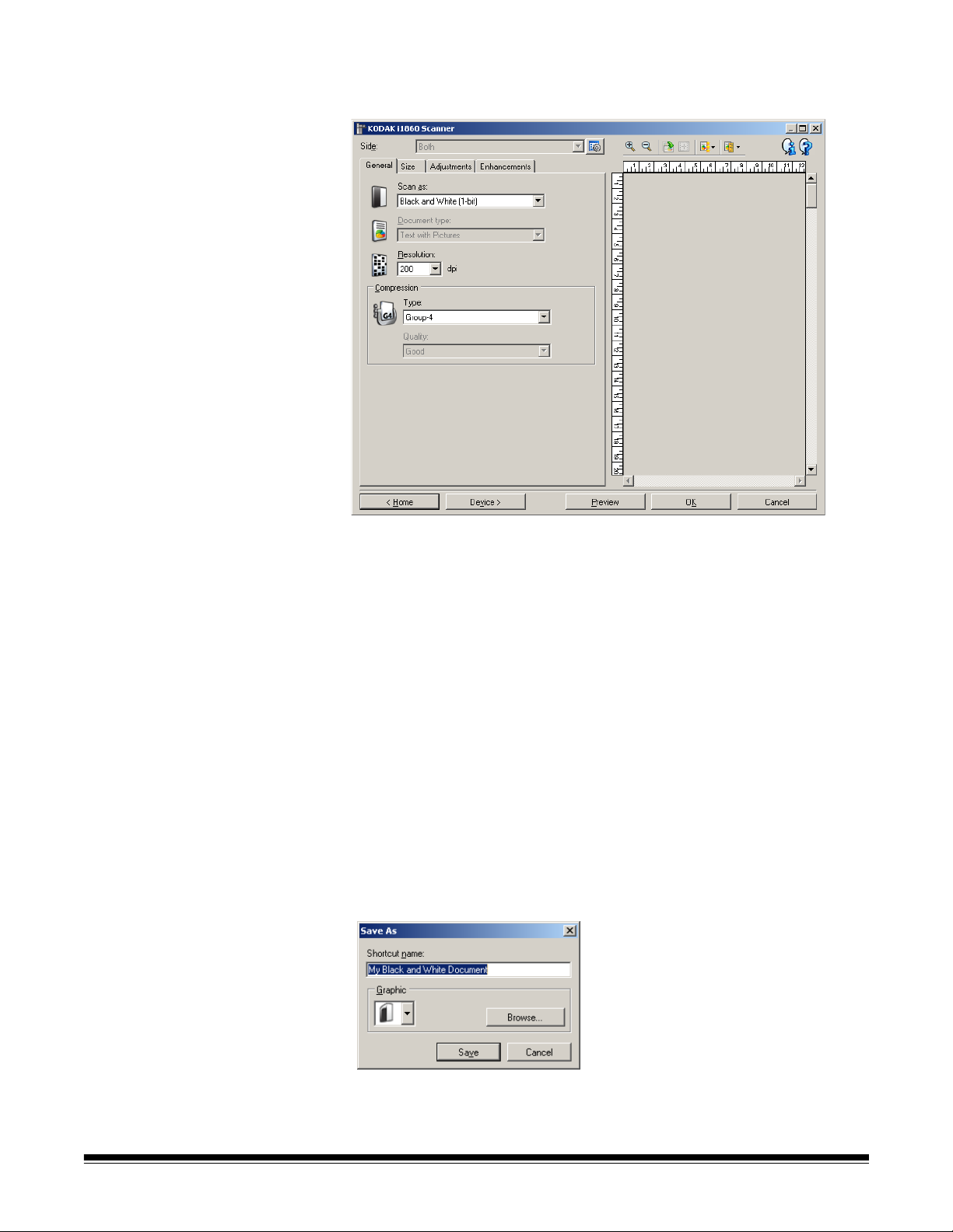
3. Select Settings on the main Kodak Scanner window. The General
tab of the Image Settings window will be displayed.
4. Select the appropriate options on the General tab.
NOTE: If necessary, review each setting on the other tabs and
make any changes.
5. Place a representative document in the input elevator.
6. Click Preview to review the resulting image.
NOTE: If the images are not acceptable, you can either select a
different predefined Setting Shortcut or make additional
changes on the rest of the tabs on the Image Settings
window.
7. Define the desired Device settings by selecting Device on the
Image Settings window to display the Device Settings window.
8. Review each tab and select the appropriate options or actions you
want the scanner to perform.
9. Select Home to return to the main Kodak Scanner window.
10.Select Save As. The Save As window will be displayed.
11. Enter a new Setting Shortcut name that is meaningful to you and
click Save.
3-46 A-61580 November 2007
Page 75

Changing Device settings 1. Select the Setting Shortcut from the main Kodak Scanner window
that closely describes your desired output.
2. Select Settings to display the Image Settings window.
3. Select Device to display the Device Settings window.
4. Before making any adjustments, browse through the tabs on the
Device Settings window to get familiar with features that are
available. See the section entitled, “The Device Settings window” for
information about these features.
5. For each option you want to use, make the appropriate selections
you want the scanner to perform when scanning.
6. When finished, select Home to return to the main Kodak Scanner
window and then select Save to save your selections to the
shortcut.
A-61580 November 2007 3-47
Page 76

4 Using the ISIS Driver
The ISIS Driver is software that communicates with the scanner. This
driver is created and maintained by EMC Captiva and is provided with
the scanner by Kodak. Many scanning applications support ISIS drivers
and this driver can be used to interface with them.
This chapter provides descriptions of the options on the tabs of the
main ISIS Driver window and how to set these options.
See the section entitled, “Starting the Scan Validation Tool” in Chapter 3
to access the main ISIS Driver window.
The main ISIS Driver window
The main ISIS Driver window provides a set of 12 tabs. You can select
each of these tabs and make any choices necessary to meet your
scanning needs. The buttons on the bottom of the window apply to all
the tabs.
Default the values on all tabs will be reset to the factory defaults.
Copy this function is only available when scanning two-sided
documents. The Copy button provides a convenient way to set up the
color, grayscale or black and white image settings on one side and
transfer them to the other. For example, if you highlight and set up
Front Image #1, you can use the Copy button to duplicate those
settings for Back Image #1.
OK saves the values set on all tabs.
Cancel closes the window without saving any changes.
A-61580 November 2007 4-1
Page 77
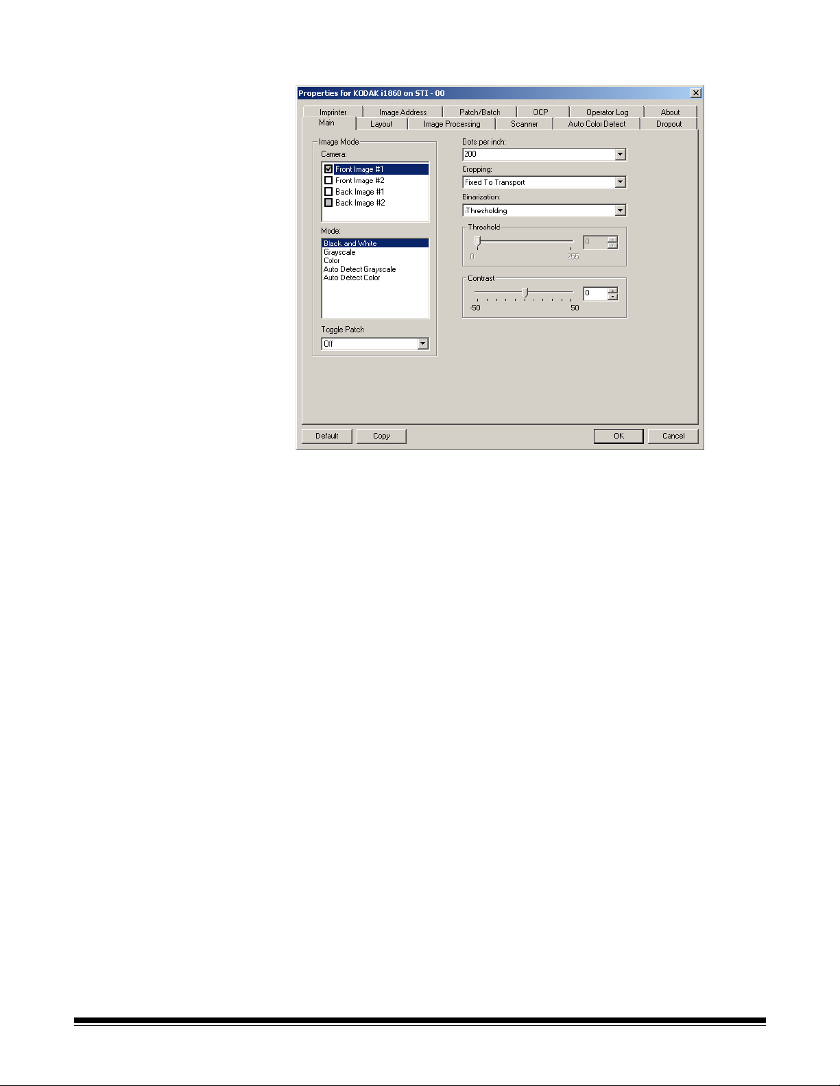
Main tab The Main tab provides the following options:
Image Mode
Camera — the selections in the Camera box list the available sides
(front and back) of an image where you can define individual image
processing values. Options include: Front Image #1, Front Image #2,
Back Image #1 and Back Image #2.
The Kodak Scanner drivers allow you to control the camera settings
independently. Some settings apply only to black and white images,
others apply to color/grayscale images. By selecting the appropriate
camera and image mode, you can control the scanner’s output.
Mode — provides the following options:
• Black and white: if you want your electronic image to represent all
elements of your document in black and white.
• Grayscale: if you want your electronic image to have a range of
varying shades of gray from black to white.
• Color: if you want your electronic image to be in color.
• Auto Detect Grayscale: sets auto color detect for grayscale. See
the section entitled, “Auto Color Detect tab” for more information.
• Auto Detect Color: sets auto color detect for color. See the section
entitled, “Auto Color Detect tab” for more information.
4-2 A-61580 November 2007
Page 78

Toggle Patch — the toggle patch is a type 4 patch that is used to
trigger the scanner to change from the current image stream (black and
white) to the alternative image stream (color/grayscale). This provides
color-on-the-fly functionality for customers who want to scan the
majority of their documents black and white with the option to switch to
color and back when desired. When a toggle patch is detected, this
determines the side(s) whose image output is toggled between black
and white and color/grayscale. Select either Off, Same Side, Both
Sides or Detect Only.
• Off: no patches will be used.
• Same Side: only the side which recognizes the patch sheet will
toggle. For example, if a patch sheet contains a patch on the front
side only, the front stream will toggle but the rear stream will not.
• Both Sides: if a patch is recognized on either the front or the rear,
both front and rear streams will toggle.
• Detect Only: this option should be used when the capture
application software (not the scanner) is responsible for determining
when to toggle. When using this option, information in the image
header will indicate that the scanner has recognized a type 4 patch.
The scanner will not take any other action.
Dots per inch (dpi) or resolution indicates the scanning resolution,
which largely determines the quality of the scanned image. The greater
the resolution, the better the reproduction. However, scanning at a
higher resolution also increases scanning time and file size.
Choose a resolution value from the drop-down list. The default is 200
dpi. Available resolutions are:
• Color/Grayscale: 100, 150, 200, 240 and 300
• Black and white: 200, 240, 300 and 400
Cropping allows you to capture a portion of the document being
scanned. All cropping options can be used with color/grayscale and
black and white images. Front and Back cropping are independent,
however, for dual stream scanning, color/grayscale and black and white
cropping must be the same per side. Only one cropping option can be
assigned per image. Select one of the following options:
• Automatic: dynamically adjusts the cropping window for different
document sizes based on the edges of the image.
• Aggressive: eliminates any residual black border on any image
edges. In order to achieve this, there is a possibility that a small
amount of image data from the edge of the document may be lost.
• Fixed to Transport: (used for batches of same-sized documents)
allows you to define the area to be imaged. Fixed to Transport
cropping is used in conjunction with paper size and page layout and
assumes you are center-feeding your documents. If you are not using
center feeding, you must select the Layout tab to define your scan
area. See the section entitled “Layout tab” later in this chapter.
A-61580 November 2007 4-3
Page 79

• Relative to Document (zone processing): used for batches of same-
sized documents, zone processing is a floating fixed crop window
(the zone) located relative to the upper left corner of a document. It
allows you to select an area on the document to be delivered in either
color/grayscale or black and white format (a separate window for
both black and white and color/grayscale may be defined). Different
parameters may be selected for both the front and back of the image.
This option may be used in conjunction with Automatic cropping
where a separate color/grayscale or black and white area to be
saved is desired. It is useful in applications where a photograph,
signature, embossment or seal appears in a consistent area for an
application (you may want that small area in color/grayscale and the
rest in black and white). To define a zone, select the Layout tab.
Binarization — these options work on grayscale images and outputs a
black and white electronic image. Their strength lies in the ability to
separate the foreground information from the background information
even when the background color or shading varies, and the foreground
information varies in color quality and darkness. Different types of
documents may be scanned using the same image processing
parameters and results in excellent scanned images.
• iThresholding: allows the scanner to dynamically evaluate each
document to determine the optimal threshold value to produce the
highest quality image. This allows scanning of mixed document sets
with varying quality (i.e., faint text, shaded backgrounds, color
backgrounds) to be scanned using a single setting thus reducing the
need for document sorting. When using iThresholding, only Contrast
can be adjusted.
• Fixed Processing (FP): used for black and white and other high
contrast documents. If Fixed Processing is selected, only Threshold
can be adjusted.
• Adaptive Thresholding (ATP): separates the foreground
information in an image (i.e., text, graphics, lines, etc.) from the
background information (i.e., white or non-white paper background).
When using Adaptive Thresholding, Threshold and Contrast can be
adjusted.
Threshold — aids in controlling the level at which a pixel is considered
black or white.
• Decreasing this setting will make the image appear lighter, and can
be used to subdue background noise.
• Increasing this setting will make the image appear darker, and can be
used to help pick up light information.
The options range from 0 to 255. The default is 90.
Contrast allows you to make an image sharper or softer. Decreasing
this setting will make the image softer and reduce noise in the image.
Increasing this setting will make the image clearer and make light
information more visible. The options range from-50 to 50. The default
is 0.
4-4 A-61580 November 2007
Page 80

Layout tab The Layout tab provides these options:
Image Orientation
• Portrait: displays the image orientation in the shape of a
conventional portrait, where height is greater than width.
• Landscape: displays the image orientation in the shape of a
conventional landscape painting, where width is greater than height.
Page Orientation — allows you to select the way you place your
documents in the scanner, Top edge first, Bottom edge first, Left
edge first or Right edge first.
Page size the default page size is set when a scanner is first
selected. You can choose a different page size using the drop-down list
box.
Scan Area — displays the Scan Area dialog box. The Scan Area
options are only available for images when the cropping option is Fixed
to Transport or Relative to Document. See the section entitled “The
Scan Area dialog box” later in the chapter for more information.
A-61580 November 2007 4-5
Page 81

Image Processing tab The Image Processing tab displays the Image Mode, Mode and Toggle
Patch information that was previously described. Refer to the section
entitled “Main tab” earlier in this chapter for descriptions.
General options • Deskew automatically straightens a document within ±0.3
degrees of the leading edge of the document. Deskew can detect up
to a 45-degree skew and correct up to a 24-degree angle at 200 dpi
or a 10-degree skew angle at 300 dpi. This option is not available
when Fixed to Transport or Relative to Document is selected.
NOTE: To prevent data loss, the document must have all four
corners within the image path.
• Add Border — allows you to add a fixed amount of border to the left,
right, top and bottom edge of the image.
Black and White options • Invert Image allows you to select how the black pixels will be
stored in the image. By default the black pixels are stored as black
and the white pixels are stored as white. Turn this option on if you
want the black pixels stored as white and the white pixels stored as
black.
• Halftone Removal enhances dot matrix text and images made
with halftone screens (e.g. newspaper photographs).
4-6 A-61580 November 2007
Page 82

Noise Filter — select one of the following: None, Lone Pixel or
Majority Rule.
• Lone Pixel: reduces random noise by converting a single black pixel
to white when it is completely surrounded by white pixels or by
converting a single white pixel to black when it is completely
surrounded by black pixels.
• Majority Rule: sets each pixel based on its surrounding pixels. The
pixel will become white if the majority of the surrounding pixels are
white and visa versa.
No Noise Filter Used Lone Pixel
Color options JPEG — uses JPEG techniques to compress the image. JPEG
compression offers a JPEG quality of Draft, Good, Better, Best and
Superior.
• Draft: maximum compression which produces the smallest image
size.
• Good: a fair amount of compression but still produces acceptable
image quality.
• Better: some compression which produces decent image quality.
• Best: minimal compression which produces very good image quality.
• Superior: the least amount of compression which produces the
largest image size.
Color Correction — select one of the following based upon the
documents you are scanning:
• Mixed: when the documents you want to scan contain a mix of text,
business graphics (bar graphs, pie charts, etc.) and line art.
• Pictures: when the documents you want to scan are comprised
mainly of photos.
• Text: when the documents you want to scan contain mostly text.
A-61580 November 2007 4-7
Page 83

Scanner tab The Scanner tab provides the following options.
Document Feeder Feeder Position — select the desired paper source.
• Normal: select when you are scanning a stack of documents of 25
sheets or less. The input elevator is in its highest position.
• 100 Sheets: select when you are scanning a stack of documents
between 100 and 25 sheets.
• 250 Sheets: select when you are scanning a stack of documents
between 250 and 100 sheets.
• 500 Sheets: select when you are scanning a stack of documents
between 500 and 250 sheets.
Automatically start scanning: if selected, the scanner will wait for up
to 10 seconds for documents to be placed in the input elevator before
scanning will begin. In addition, once the input elevator has been
emptied, the scanner will automatically resume scanning when paper is
placed in the input elevator. The scanner will wait the amount of time
specified by the document feeder timeout.
Lightweight paper: improves output stacking when scanning
lightweight paper. When selected, the scanner will increase the gap
between documents in order to allow each document to settle in the
output tray before the next document gets to the output tray.
NOTE: Using this option will decrease overall throughput.
4-8 A-61580 November 2007
Page 84

Timeout On — allows you to select the amount of time the scanner will wait once
the last document enters the feeder before the timeout occurs. You can
turn this option off or set a time from 1 to 300 seconds.
Response — allows you to specify the action that will be taken when
the transport timeout has been reached.
• End Job: stops the feeder and the transport but leaves the scanner
enabled. Scanning may be resumed by touching the Scan button on
the touchscreen.
• Stops Feeder and Transport: scanning will stop and control will
return to the scanning application (i.e. ends the job).
Power Saver This option allows you to set the amount of time the scanner has to be
inactive before going into power saver mode. You can turn this option
off or set a time from 5 to 60 minutes.
Multi-feed Detection options
Multifeed detection aids in document processing by detecting
documents that may go through the feeder overlapped. Multifeeds can
happen due to stapled documents, adhesives on documents, or
electrostatically charged documents
Length Detection if you enable this option, select the minimum
length of the document that can be scanned with a multi-feed being
detected. A value of 0 indicates no length detection. Length detection
can be used when scanning same-size documents. The maximum
value is 34.5 inches.
• Auto Set: automatically sets the maximum length value to .50-inch
(1.27 cm) greater than the length of the currently selected page size.
Ultrasonic Detection — check this option to set multi-feed detection.
Sensitivity — controls how aggressively the scanner will work to
determine if more than one document is fed into the scanner. Multifeeds
are triggered by detecting air gaps between documents. This allows
multifeed detection to be used with job sets containing documents with
mixed thicknesses.
•(none)
• Low: least aggressive setting and is less likely to detect labels, poor
quality, thick or wrinkled documents as multi-fed documents.
• Medium: use if your job set has varying document thicknesses or
labels attached to the document. Depending on the label material,
most documents with labels should not be detected as a multi-fed
document.
• High: most aggressive setting. This is a good setting to use if all
documents are similar in thickness to 20-lb. bond paper.
NOTE: Regardless of the setting, “sticky” notes will be detected as
multi-fed documents.
A-61580 November 2007 4-9
Page 85

• Low: least aggressive setting and is less likely to detect labels, poor
quality, thick or wrinkled documents as multi-fed documents.
• Medium: use Medium sensitivity if your Settings Shortcut has varying
document thickness or labels attached to the document. Depending
on the label material, most documents with labels should not be
detected as a multi-fed document.
• High: most aggressive setting. This is a good setting to use if all
documents are similar in thickness to 20-lb. Bond paper.
Active Sensors — three sensors cover the width of the paper path. In
order for multi-fed documents to be detected correctly, they must pass
under one of these sensors.
Left, Middle, Right: this allows you to select which sensor(s) you want
turned on. For example, if you know that the left side of the document
has a “sticky” note on it, you can turn off the left sensor.
Action — select an option of how you want the scanner to perform if it
detects a multi-fed document.
• Detect Only: the scanner will beep (if the scanner volume is on) and
the condition will be logged in the scanner and continue to scan.
• End Job: scanning will stop and control will return to the scanning
application (i.e., ends the job). Verify that the paper path has been
cleared and restart the scan session from the scanning application.
• Stop Feeder and Transport: scanning will stop but the scanning
application will be waiting for additional images (i.e., stops the
feeder). Scanning may be resumed by touching Resume on the
touchscreen. Scanning may be stopped by touching End Job on the
touchscreen or via the scanning application.r
4-10 A-61580 November 2007
Page 86

Operations Calibrate — displays the Calibrate dialog box which allows you to
perform an Image Chain or UDDS calibration. Only calibrate the
scanner when prompted to do so.
• Image Chain: optimizes your scanner to achieve the best image
quality and feeding performance. Frequent calibration is not
necessary or recommended.
• UDDS: ensures that the ultrasonics system that detects multi-feeds
and document edges is properly adjusted for best performance.
A-61580 November 2007 4-11
Page 87

Use the calibration target provided with your scanner.
1. Click Calibrate. The Calibrate dialog box will be displayed.
2. Select Image Chain or UDDS from the drop-down box.
• If you select Image Chain, use the calibration target provided
with your scanner. Be sure to use a good, clean calibration target.
Place the calibration target in the input elevator face up and click
OK.
IMPORTANT:If the White Background Accessory is installed, it
must be replaced with the black background strips,
and the scanner must be restarted prior to
calibration.
• If you select UDDS, place a 20 lb. or 75 g/m
2
bond sheet of paper
in the input elevator. Do not use the calibration target and click
OK.
3. Click Start. While calibration is being performed a status will be
provided in the Status box.
4. Click Done when the calibration is successful.
4-12 A-61580 November 2007
Page 88

Auto Color Detect tab The Auto Color Detect tab provides the following options.
Color Content Select one of the following options for automatic color detection.
• Low: documents require only a small amount of color to be saved as
color or grayscale images. Used for capturing documents that are
primarily black text with small logos, or contain small amounts of
highlighted text or small colorful photos.
• Medium: documents require more color, as compared with the Low
option, before they are saved as color or grayscale images.
• High: documents require more color, as compared with the Medium
option, before they will be saved as color or grayscale images. Used
for distinguishing documents containing medium- to large-size
colorful photos from plain black text. Photos with neutral colors may
require adjustments to the Color Amount or Color Threshold values in
order to be captured correctly.
• Custom: makes the Color Amount and/or Color Threshold options
available.
NOTE: When setting Auto Color Detect values, start with the
Medium option and scan a typical job set. If too many
documents were returned as color/grayscale vs. black and
white, then change to the High option and re-run the job. If
too few documents were returned as color/grayscale vs.
black and white, then change to the Low option and re-run
the job. If none of these options provide the desired result,
select Custom to manually adjust Color Amount and/or Color
Threshold.
A-61580 November 2007 4-13
Page 89

Color Amount: the amount of color that needs to be present in a
document before it will be saved as either color or grayscale. As the
value of Color Amount increases, more color pixels are required. Valid
values are 1 to 200.
Color Threshold: the color threshold or intensity (i.e., pale blue vs.
dark blue) at which a given color will be included in the color amount
calculation. A higher value indicates that a more intense color is
required. Valid values are 0 to 100.
Learn If Low, Medium and High options do not give you the desired results,
use the Learn option.
1. Click Learn and follow the prompts.
2. Place at least 5 representative color documents in the input elevator
and click OK. These documents will be analyzed and the
recommended color amount will be calculated.
3. Write down the Color Amount and Color Threshold values that
are displayed in the dialog box as these are the settings you will be
required to use in your application.
NOTE: These settings were calculated based on the representative
color documents scanned. If these values do not provide the
desired results with your production job set, you may need to
manually adjust the Color Threshold.
4-14 A-61580 November 2007
Page 90
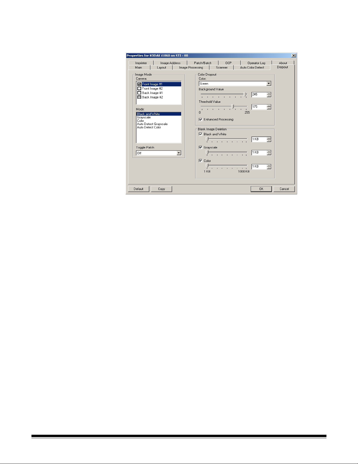
Dropout tab The Dropout tab displays the Image Mode, Mode and Toggle Patch
information that was previously described. Refer to the section entitled
“Main tab” earlier in this chapter for descriptions.
Color Dropout Color dropout is used to eliminate a form's background so that only the
entered data is included in the electronic image (i.e. remove the form's
lines and boxes). For black and white images, these settings effect the
grayscale version of the document which the scanner analyzes to
produce that electronic image. You can select a Red, Green or Blue
dropout color.
Background Value: allows you to select the grayscale value to replace
the dropped color with. It is suggested that this value be higher than the
Threshold value selected on the Adjustments tab in order for the
dropped color to appear to be part of the background. The values range
from 0 to 255. Default: 245.
Threshold Value: allows you to adjust how the scanner identifies the
color to be dropped. The values range from 0 to 255. Default: 175.
Enhanced Processing — enable or disable this option to achieve the
highest read rate for your production OCR processing. The default is
Enabled. For example, if you enable Enhanced Processing and
achieve an 87% read rate, and achieve a 93% read rate with this option
disabled, then you would disable this option. Compare these
percentages with identical image processing parameters and the same
document samples.
Blank Image Detection Use the slider bar to select the minimum image size that the scanner
will consider to be non-blank. Any image that is less than this value will
be considered blank and will not be given to the scanning application.
The values range from 1 to 1000 KB (1 KB equals 1024 bytes). You
must specify a blank image size for each image type (Black and White,
Grayscale, and Color) you want to delete. The default is None, which
means you keep all images.
A-61580 November 2007 4-15
Page 91

Imprinter tab The Enhanced Printer provides a vertical print capability and supports
alphanumeric characters, date, image address, time, document count
and custom messages. All print information is captured in the image
header of each document.
Mode
• Do not print: disables the options on the Imprinter tab.
• Print on the front of document before scanning: enables the
options on the Imprinter tab.
Level — choose the level of the document that you want the specified
print string to be printed on. For example, if you use three level image
addressing, you can print the date on your level 3 document, nothing on
level 2 and document count on level 1. Image addressing must be
enabled for this option to be available.
4-16 A-61580 November 2007
Page 92

Defining your print string Format Template — allows you to define your print string. The
maximum amount of characters for the print string is 40 characters
(including spaces).
Date — if you want to add a date to the print string, select one of the
following formats:
• Format: MMDDYYYY, DDMMYYYY, or YYYYMMDD.
• Delimiter: select one of the following separators: Slash: /,
Hyphen: -, Period: . , Blank or none. For example: 08/24/2007,
08-24-2007, 08.24.2007 or 08 24 2007 or 08242007 (none).
Counter — if you want to add a Counter to the print string, you can
enter one of the following options:
• Initial Value: this value is used to assign the document count for the
next document entering the transport and is incremented sequentially
by the scanner unless another document count is received from the
host. This value is returned in the image header.
• Field Width: used to control the width of the document counter.
Values range from 1 to 9.
• Format: the format in which the printed image address appears
when printed is defined on the Image Address tab. The printed image
address may appear in one of three formats:
- Display Leading Zeros format (e.g., 004.003.002.001)
- Compress Leading Zeros format (e.g., 004. 3. 2. 1)
- Suppress Leading Zeros format (e.g., 004.3.2.1)
NOTE: The format chosen does not effect the fixed field of the image
address; it is always displayed and printed in its entirety. In
the example above, 004 has been defined as a fixed field.
Top margin — allows you to define the distance from the lead edge
before the print string begins. Enter the desired amount in the text box.
NOTE: Printing automatically stops 6.3 mm (1/4-inch) from the trailing
edge of the document even if the information has not been
completely printed.
Units — select Inches, Centimeters or Pixels.
Font — two different character styles, referred to as Normal and
Large, are available.
Rotations — you can select either 90, 180, 270 or Automatic.
• Automatic — the scanner will analyze each document to determine
how it was fed and will rotate the image to the proper orientation.
NOTES:
- There must be a sufficient amount of text on the page for this
option to work properly.
- This option is designed to work best with Latin-based characters
(e.g., English, Dutch, French, German, Italian, Spanish).
Horizontal print position The horizontal print position is set manually on the scanner. See
Chapter 4, The Enhanced Printer and Patch Readers, in the User’s
Guide for information on changing the horizontal print position.
A-61580 November 2007 4-17
Page 93
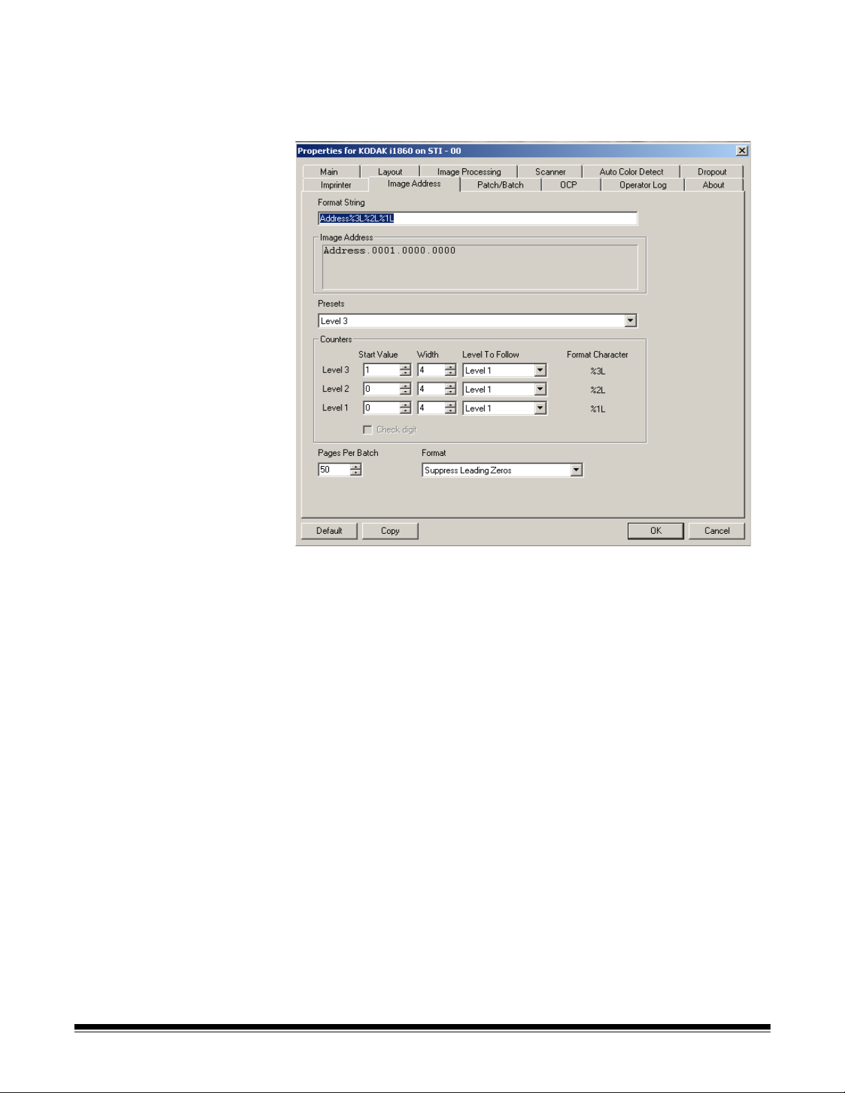
Image Address tab Image addressing is used for document tracking, batch control and
image management. The Image Address tab allows you to set an
image address starting point. The scanner will increment the image
address based on how you set up the image address rules on this tab.
Format String — this text field allows you to structure your image
address. Fixed field information entered in this field will be reflected in
the Image Address area in Fields A through D. To indicate the position
of an image address level use the format character (%3L - Level 3, %2L
- Level 2, %1L - Level 1), which represents the level. For image
address levels the value indicated in Fields A through D will be the start
value as defined in the Counters area Start Value field. The format
string in the sample screen above represents a fixed field value of
address and a 3 level image address.
The i1800 Series Scanners have more options available for image
addressing schemes with the following guidelines:
• You may define from 0 to 4 fixed fields. Fixed fields can be a
maximum of 9 characters.
• Only one field may be assigned to a level. You are only allowed one
Level 1 field, one Level 2 field and one Level 3 field.
• There is no requirement to have any Level field.
4-18 A-61580 November 2007
Page 94

Image Address fields — displays the starting image address. The
values in this field reflect information from the Format String area and
the Start Value field in the Counters area. Each field can have a
maximum width of 9 characters. The total image address cannot
exceed 27 characters (30 with 3 delimiters).
Presets — you can use the selections in the field to automatically fill in
the format string field. The options are:
• Custom: enter your desired values.
• Level 3: Address%3L%2L%1L
• Level 2: Address%2L%1L
• Level 1: Address%1L
• Level 3 Offset: Address%3L%2L
• Level 2 Offset: Address%2L
You can have no fixed field or enter any fixed field value. The default
fixed field value is Address.
Counters — for each image address level enter a Start Value, Width
and make a Level to Follow Level selection.
• Start Value: the start value is reflected in the image address in the
field designed by the format string.
• Width: a value of 0 indicates that no image address level will be
used. Widths cannot exceed 9 characters.
• Level to Follow: these are the rules the scanner follows to set the
next image address level if there are no other inputs. For example,
patch sheet or end of batch processing. You will have to define a
level to follow level for each of the level fields you defined in your
image address.
NOTE: The total value of the Width column plus the number of
characters in all fixed fields cannot exceed 27 characters.
Check Digit — this option is only displayed if the scanner is configured
with a Check Digit alteration file.
Pages Per Batch — refer to the Batch/Patch tab for more information.
This number is displayed on this tab to be used as a reference while
formatting your image address.
Format — select the format of the image address string used by the
printer and how it is displayed on the touchscreen. The following
choices are available for printing the counter format.
• Display Leading Zeros format (e.g., 0009). This is the default.
• Suppress Leading Zeros format (e.g., 9)
• Compress Leading Zeros format (e.g., 9)
A-61580 November 2007 4-19
Page 95
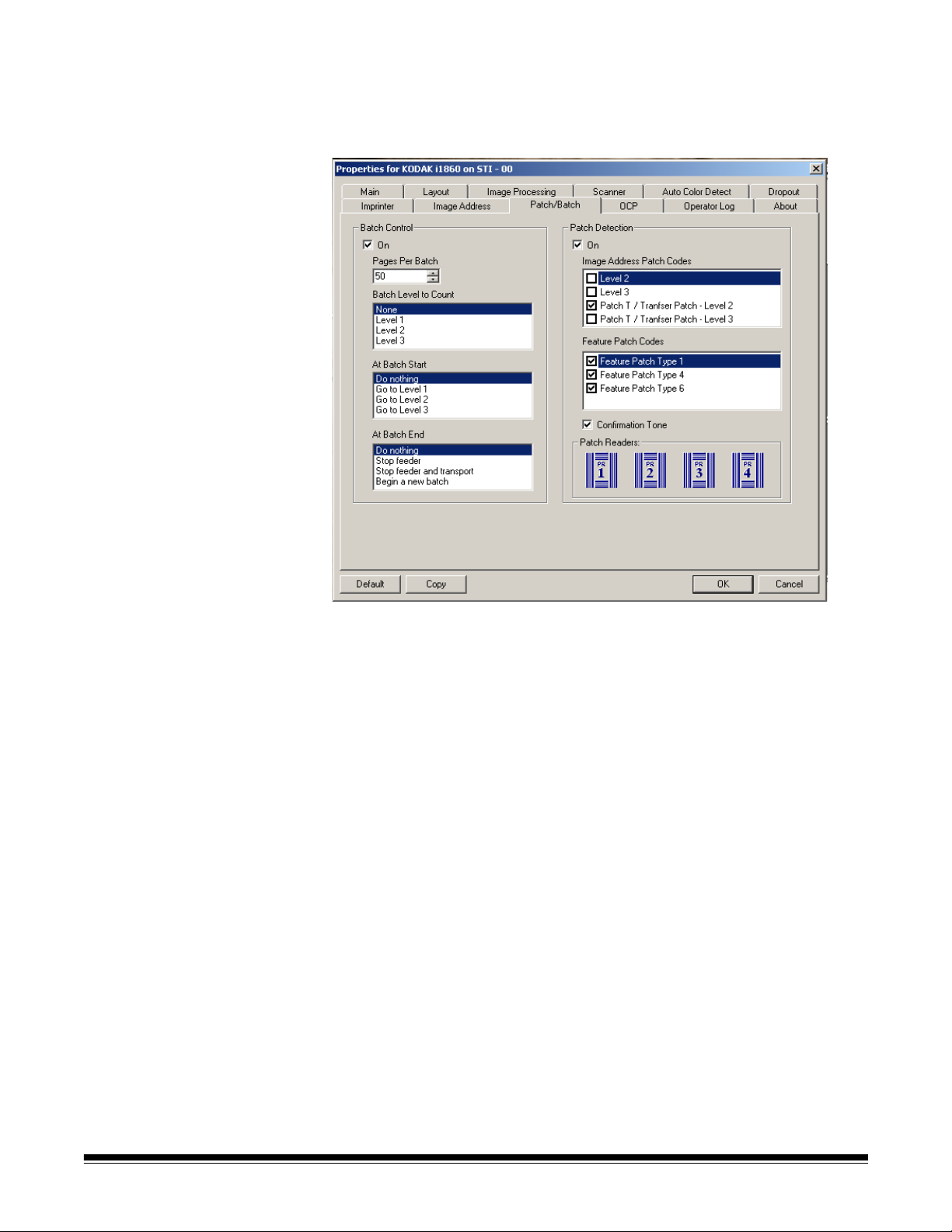
Batch/Patch tab The Batch/Patch tab provides batch and patch functionality. Batching is
the operation of counting pages or documents. The Patch tab provides
choices of what patch type to recognize. One or more patches can be
selected at a time.
Batch Control The batch function allows you to define the level to count the number of
documents in the batch and any actions to be taken at the beginning
and end of a batch.
On — enables batch separation.
Pages per Batch — defines the batch size which is the number of
documents to be counted before performing a predefined action.
Batch Level to Count — sets the level to count. You can select Level
1, Level 2 or Level 3. The level you choose to count must exist in the
image address template as defined on the Image Address tab.
At Batch Start — defines the action to be taken before processing the
first document in a batch. You can select Go to Level 1, Go to Level 2,
Go to Level 3 or no action.
At Batch End — defines the action to be taken after processing the last
document in the batch. You can select Stop Feeder, Stop Feeder and
Transport (End of Job), Continue and Begin New Batch or no
action.
4-20 A-61580 November 2007
Page 96

Patch Detection Patch Control allows you to select what patch types to recognize. One
or more patches can be selected at a time.
On — check this box to enable patch recognition.
Image Address Patch Codes — these patch types are used for image
addressing. When the Patch Reader detects a patch, it automatically
assigns a new image address to the new document. This eliminates the
task of trying to determine where one document stops and the next
starts when an operator is viewing electronic images. It provides a
hierarchical document structure and offers an auto-batching
alternative.You can select Level 2, Level 3, Patch T / Transfer Patch -
Level 2 or Patch T / Transfer Patch - Level 3.
The Patch Reader controls document level changes by automatically
sensing a predefined patch code and changing the document level
accordingly.
Patch 2 — assigns a Level 2 to the current document
(Do not use these patches for
production - they are not to spec)
Patch 3 — assigns a Level 3 to the current document
(Do not use these patches for
production - they are not to spec)
Patch T/Transfer Patch — assigns a predetermined level to the next
document. Defined by selecting Level 2 or Level 3 in the Definition box.
(Do not use these patches for
production - they are not to spec)
A-61580 November 2007 4-21
Page 97

Feature Patch Codes — these patch types can be used by the host for
post-scan image control (they are not used for image addressing). For
example, use these patch types for changing between black and white
and color/grayscale imaging or workflow control.
Patch 1
(Do not use these patches for
production - they are not to spec)
Patch 4/Toggle Patch
image addressing - disabled
(Do not use these patches for production - they are not to spec)
NOTE: the Toggle patch is a Type 4 patch that is used to trigger the
scanner to switch from the current image stream (black-andwhite) to the alternative image stream (color/grayscale). When
image addressing is disabled, the Patch Readers are also
disabled. However, a Toggle patch can still be detected.For
more information, see the section entitled, “Controlling image
transfer order” in Chapter 2.
Patch 6
(Do not use these patches for
production - they are not to spec)
Confirmation Tone — the confirmation tone may be used to signal that
a patch has been recognized. The default is no confirmation tone.
Patch Readers — this graphical representation corresponds to the
physical patch reader location in the scanner.
Select up to four patch reader(s) that you want to read patches.
4-22 A-61580 November 2007
Page 98

OCP tab The OCP tab is used to assign actions the operator uses from the
Operator Control Panel. Function Key #1, Function Key #2 and
Function Key #3.
Function Keys — available functions are:
• End of Job
• Terminate Batch
• Omit Multifeed Detection on Next Document
• Do Not Print on Next Document
• Omit Patch Reading on Next Document
A-61580 November 2007 4-23
Page 99

Operator Log tab The Operator Log tab provides a listing of any errors that have been
encountered.
You can either save this information to a file by clicking the Save icon,
or click the Copy icon to copy the information to the clipboard.
About tab Displays information about your scanner and driver.
4-24 A-61580 November 2007
Page 100

Scan Area dialog box The Scan Area dialog box is only available for images when the
Cropping option selected on the Layout tab is either Fixed to
Transport or Relative to Document.
To access the Scan Area dialog box, select Scan Area on the Layout
tab.
NOTE: Select the side and image to be defined by highlighting Front
Image #1, Front Image #2, etc. based on the cropping option
selected for each of these on the main ISIS Driver tab. The scan
areas defined for all camera selections are independent.
Page Size the default paper size is set when a scanner is first
selected. You can choose a different paper size using the drop-down
list box.
NOTE: Page Size and Page Layout selections also appear on the
Layout tab. If you make a change on the Scan Area dialog box,
the same selections appear on the Layout tab and vice versa.
The Page Layout area allows you to select either Portrait or
Landscape.
• Portrait will display the image orientation in the shape of a
conventional portrait, where height is greater than width.
• Landscape will display the image orientation in the shape of a
conventional landscape painting, where width is greater than height.
A-61580 November 2007 4-25
 Loading...