

Page 1

Document Scanner 9500
A-61092
Part No. 1E8133
User’s
Guide
Page 2

Safety Information for Installation Instructions for the
Document Scanner 9500
Science
IMPORTANT: Equipment shall be installed by qualified
personnel.
WARNING: Dangerous voltage. Disconnect the main
power before installation.
Kodak Digital
CAUTION: Hot surface, avoid contact
ATTENTION: Eviter le contact, pieces brulantes
VORSICHT: Heisse oberflaeche, beruehrung vermeiden
Page 3

Safety Information for User/Installation Instructions for the
Automatic Document Feeder
Digital Science
IMPORTANT: Equipment shall be installed by qualified
personnel.
WARNING: Dangerous voltage. Disconnect the main
power before installation.
Kodak
CAUTION: Moving parts, avoid contact
ATTENTION: Eviter le contact, pieces en mouvement
VORSICHT: Bewegliche teile, beruehrung vermeiden
Page 4

1 Introduction
The
Kodak Digital Science
medium- to high-resolution rotar y scanner designed for high-volume
digital capture of business documents. The Document Scanner 9500
captures printed characters, handwritten t ext, and graphics from
documents of various sizes.
NOTE: Illustrations in this User’s Guide are shown using the semi-
automatic feeder.
Document Scanner 9500 is a high-speed,
Scanner features
The Document Scanner 9500 has the following features:
• Scans up to 144 pages per minute (standard sized documents fed
in landscape orientation; continuous transport using the semiautomatic feeder).
• High-speed scanning and image resolution.
◊ Scanner 9500 scans 160 landscape (A4 size) or 120 port r ait
(8 ½ x 11-inch) documents per minute at 200 dpi or 107
landscape (A4 size) or 80 portrait (8 ½ x 11-inch) documents per
minute at 300 dpi.
• Handles documents of up to 2.5 to 20 in. (64 to 508 mm) long,
2.5 to 12 in. (64 to 305 mm) wide, and 0.014 in. (0.36 mm) thick.
The gap release feature allows thicker documents to be scanned.
NOTE: Documents longer than 20 inches can be scanned, but might
require special handling.
• Easy-to-reach control panel keys, identified by gr aphic symbols.
• A high-speed document transport system.
• A two-line, 80-character display for status information and operator
messages.
• Full programmability of 18 application modes, with override
capability.
• Linked modes allow the image address to be carried over from one
mode to another.
• Programmable keys to perform commonly-used functions.
• A transport-on function that allows 27 of the function codes to be
executed while the transport is running.
• Audible tones for selected funct ions, such as footswitch, patch
reading, etc.
• English or other language message display.
• A large, built-in workshelf.
• An adaptable, modular design for easy addition of accessories.
A-61092 September 1999 1-1
Page 5

Scanner options
The following options are available for use with your scanner:
• A choice of feeders (e.g., an optional check feeder, semi-automatic
document feeder or automat ic docum ent feeder)
• A choice of exit hoppers (e.g., an optional check stacker)
• A Footswitch for document level control
• An Endorser for stamping information on documents
• A 600 dpi, 12-character ink-jet printer which supports black and
magenta ink colors
• A Patch Reader for automatic document level control
• End-fed patch capability
• A Bar Code Reader for decoding encoded information
• A skew/length monitor
• A multi-feed detection device
• A workstation console, left or r ight position
1-2 A-61092 September 1999
Page 6

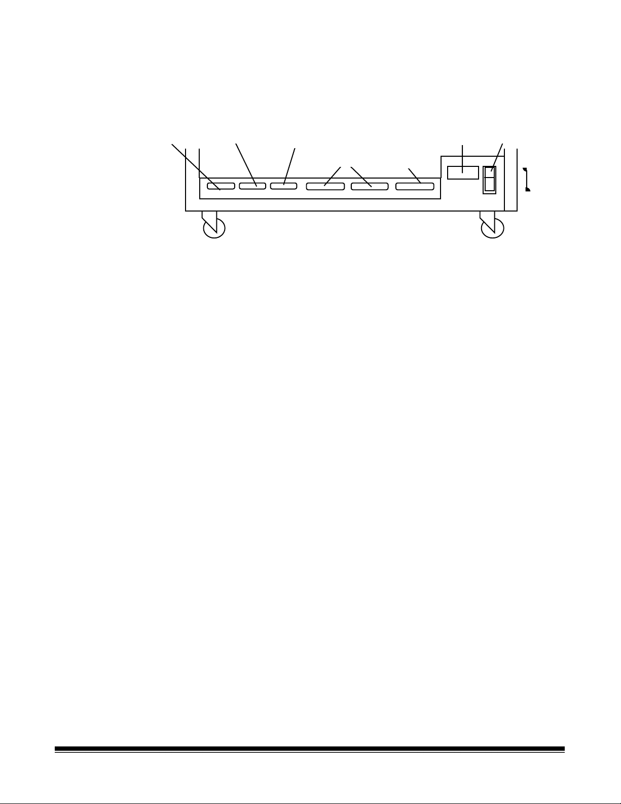
Scanner components
The following illustrations and descriptions will help you locate and
become familiar with scanner components.
Top cover
Exit hopper
Control panel
Right-side access door
Feed and
separator
rollers
Feed tray
Gap adjustment knob
(semi-automatic feeder only)
Side panel switch
Gap release lever
Control panel — contains the status display, indicators, and operating
keys used to control the scanner.
Feed and separator rollers (semi-automatic feeder only) — provides
smooth document feeding of various sizes and textures.
Feed tray — holds documents prior to feeding.
Top cover — provides access behind the transport area
.
Exit hopper — collects documents after they have been scanned.
Right-side access door — provides access to the transport system
components.
Side panel switch — allows you to turn the transport system on and
off.
Gap release lever — allows you to open the feed gap to allow thicker
documents to be fed into the transpor t .
Gap adjustment knob (semi-automatic feeder only) — allows you to
manually adjust the space between the feed and separator rollers f or
documents of varying thicknesses.
A-61092 September 1999 1-3
Page 7
Rear view
J32
Computer
interface 1
(COIN 1)
Computer
interface 2
(COIN 2)
J30 J31 J45
Computer
interface 3
(COIN 3)
SCSI ports
Not Used
J33 J46
Power
cord
Main power switch
ON
OFF
Computer interface 1 (COIN1) — service/diagnostic inter face.
Configures the scanner and runs diag nostics.
Computer interface 2 (COIN2) — bar code interf ace. Transfers
commands between the scanner and external devices/subsystems.
Computer interface 3 (COIN3) — SCSI diagnostic port interface.
System debugging and monitoring SCSI - host computer
communications.
SCSI ports — SCSI interface connection for the scanner.
Power cord — plugs into an appropriat e power outlet .
Main power switch — turns main power to the scanner on and off.
1-4 A-61092 September 1999
Page 8
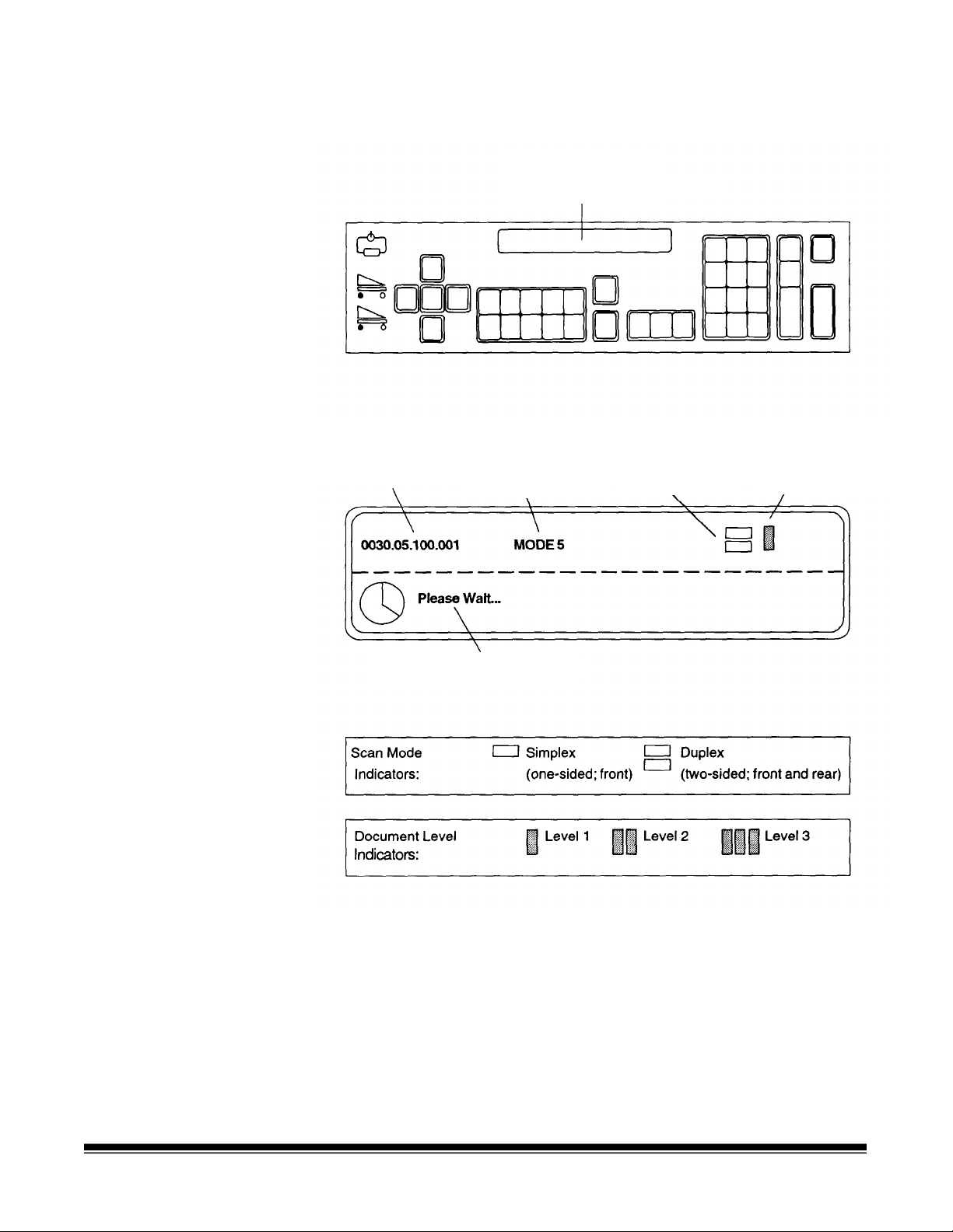
Status display — indicates the image address, scan mode, document
level and operator messages.
Two-line status display
Image address
Mode name/number
Operator message
Scan mode
indicator
Document level
indicator
A-61092 September 1999 1-5
Page 9
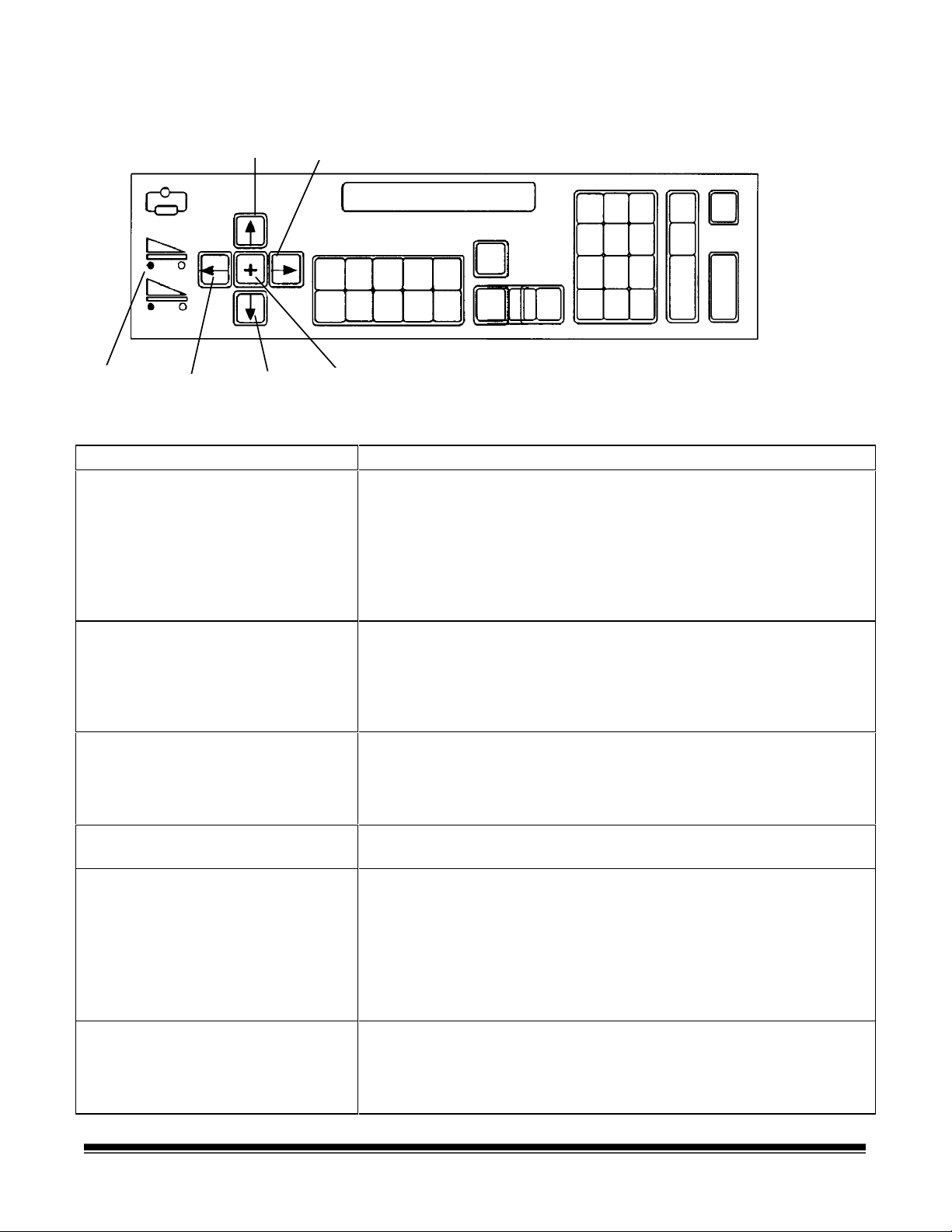
Operating keys and indicators
Scanner
buffer
indicators
Left arrow
Up arrow
Down arrow
Right arrow
Plus key
Key/Indicator Function
Scanner buffer indicators Indicates the amount of image buffer space available.
A full image buffer is represented by a single light in t he display;
an empty image buffer is repr esented by all lights in the display.
• The upper indicator represents the image buffer for f r ont side
images.
• The lower indicator represents the image buffer for rear side
images.
Left arrow (←)
The Left arrow allows you to:
• Decrement values at a slower rate.
• Backspace, delete the last keystroke, or clear messages in
the status display.
• Enter an alphanumeric character in t he im age address.
Down arrow (↓)
The Down arrow allows you to:
• Decrement values at a faster r ate.
• Decrease a data value when used with certain functions.
• Enter an alpha character in the image addr ess fixed field.
Plus key (+) Inputs a value for the image address. When pressed, it allows a
field to remain unchanged.
Right arrow (→)
The Right arrow allows you to:
• Increment values at a slower rate.
• Display additional messages in the status display. A blinking
cursor over the arrow in the display indicates there are
additional messages. Press the Right ar row key to display
these messages.
• Enter an alphanumeric character in the image address.
Up arrow (↑)
The Up arrow allows you to:
• Increment values at a faster rate.
• Increase a data value when used with certain functions.
• Enter an alpha character in the image addr ess fixed field.
1-6 A-61092 September 1999
Page 10
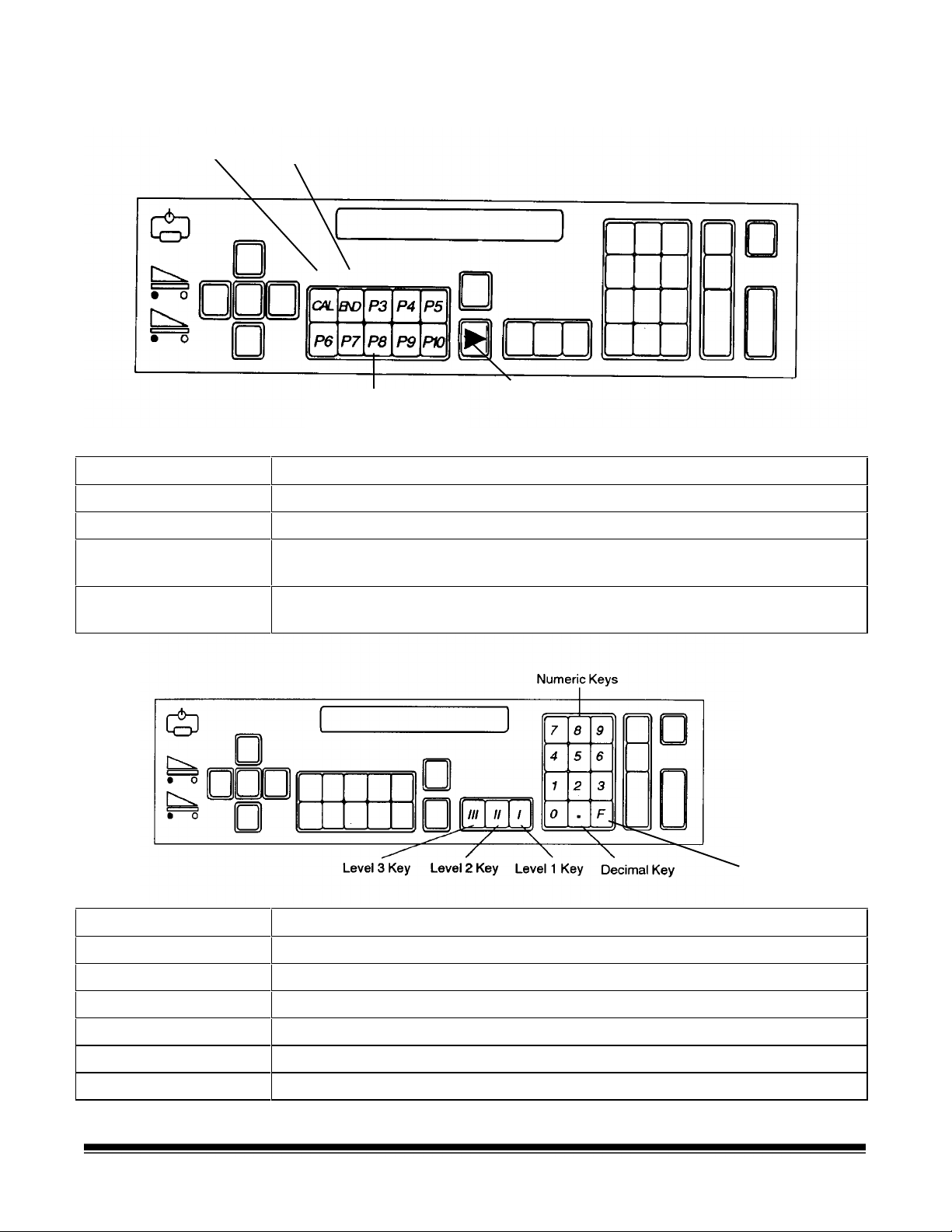
Operating keys and indicators
Calibration key
End
Programmable keys
Jog key
(P keys)
Keys/Indicators Function
CAL Starts the calibration process.
END Informs the host comput er when a batch or job has ended.
Programmable keys
(P keys)
Perform specific functions. The P keys have default values; any or all of the
defaults may be overridden/reprogramm ed at installation.
Jog Momentarily turns on (jogs) the transport system t o help clear document
jams.
F Key
Keys/Indicators Function
Numeric keys (0-9) Enter numeric data such as an image address or function code.
F key Selects one of the available functions, when used with the numeric keys.
Decimal key Inserts a field separator in an image address.
Level 1 key Identifies the next document fed into the scanner as a Level 1 document.
Level 2 key Identifies the next document fed into the scanner as a Level 2 document.
Level 3 key Identifies the next document fed into the scanner as a Level 3 document.
A-61092 September 1999 1-7
Page 11

Operating keys and indicators
Key/Indicator Function
Clear/Cancel The C ke y allows you to:
• Cancel a function without changing the preset values.
• Clear the status display after executing specified function codes.
• Clear an operator message fr om the status display.
Run Turns on the feeder and transport system.
NEXT Allows you to enter the next document image address.
Stop Allows you to stop the feeder and transport system. Docum ents st ill in the transport
system will be scanned and placed in the exit hopper before the transport system
stops.
Enter Enters data for a function code or an image address chang e.
Confirmation tone/alarm
The confirmation tone/alar m is located under the control panel and
sounds when one of the following conditions occur:
• Run is pressed (one long tone).
• Stop or End is pressed (many short tones f ollowed by a long tone) .
• Feeder clutch engages/disengag es ( one short tone).
• Incorrect key is pressed (three shor t t ones).
• Document skew is greater than what is setup in the skew
parameter, or when a document is shorter or longer than the
specified length parameters (one shor t tone).
• A bar code is detected (if the accessory is enabled and the
confirmation tone is enabled).
• A patch code is detected (if the accessory is enabled and the
confirmation tone is enabled).
• The Footswitch is detected (if the accessory is enabled and the
confirmation tone is enabled — one short tone).
1-8 A-61092 September 1999
Page 12

2 Getting Started
The following steps are necessary to prepare the scanner for operation.
Procedures on how to perform these steps are described in t his
chapter.
1. Turn on the main power switch.
2. Turn on the side panel switch.
3. Select the language display.
4. Calibrate the scanner.
5. Adjust the feed and separator roller gap.
6. Adjust the feed shelf posit ion.
7. Adjust the feed shelf side guides.
8. Adjust the exit hopper side guides and end stop.
9. Change the deflector (if required).
10. Prepare documents for scanning.
Turning on the scanner
Selecting the language display
Follow the steps below to turn on the power to the scanner.
1. Turn on the main power switch (located at the rear of the scanner).
NOTE: It is not necessary to turn off the main power switch during
normal daily operations.
2. Turn on the side panel switch.
Wait until the status display indicators are lit and an operating display
appears before you continue.
The scanner may have been configured at installation to allow use of a
second language in the status display. The language used (French,
German, Italian, Spanish, or other) is defined during installation. If
available, the alternate language display may be accessed using
function code F19.
A-61092 September 1999 2-1
Page 13

Calibrating the scanner
Calibration sets the intensity of the lamps, which contribute to the
overall quality of the scanned document image.
The scanner should be calibrated:
• at least once a day when the scanner is turned on using the side
panel switch — prior to scanning documents
• any time the scanner is turned on using the main power switch
• if image quality is poor
• after changing lamps
• after cleaning the scanner or imaging guides
Calibrate the scanner using a calibration targ et (sheet of paper) that is:
• Blank
• Clean
• Matte finish (not glossy)
• White or the same color as the background color of the documents
to be scanned. If you are scanning a variety of color ed docum ents,
use a white calibration target.
• Wider than t he docum ents you are going to scan (i.e., to scan 8.5 x
11 inch (215.9 x 279.4 mm) documents, the calibration target should
be wider than 8.5 inches (215.9 mm). The recommended width for
the calibration target is 12 inches (300 mm).
To calibrate the scanner:
1. Verify the main power and side panel switches are on. A normal
operating status display should appear.
2. Press CAL or enter function code F37 to start the calibration
sequence.
3. Insert the calibration target int o t he feeder.
When calibration is successful, the status display returns to a normal
operating display.
2-2 A-61092 September 1999
Page 14

Unsuccessful calibration
If calibration is not successful, a message appears in the status display.
You may need to:
• Verify you are using a clean, blank sheet of paper as a calibration
target.
• Verify there is not a document already in the document path. (Refer
to the section entitled, “Clearing the document path” in Chapter 7.)
• Clean the imaging guides. (Refer to the section entit led “Cleaning
the imaging guides” in Chapter 5.)
• Calibrate the scanner again. If calibration fails again, change t he
lamps. (Refer to the section entit led, “Replacing the exposure
lamps” in Chapter 5.)
If you have done all of the above and calibration still fails, contact your
service representative.
Preparing documents for scanning
Before you begin processing documents, m ake certain that the
documents may be fed through the scanner easily.
• Remove any staples, rubber bands, loose mending tape, or paper
clips from the documents to be processed.
• Straighten wrinkled edges and tape any torn documents.
• Trim ragged edges.
When using t he semi-automatic feeder, make certain all documents are
of similar size, texture, thick ness and weight , and the leading edges of
all documents are aligned.
A-61092 September 1999 2-3
Page 15

Adjusting the feed
d
and separator roller
(semi-automatic
gap
feeder only)
IMPORTANT:
The gap adjustment k nob on t he control panel increases or decreases
the space between the feed and separator rollers. The gap must be
adjusted properly for smooth t r anspor tat ion of documents without
document overlap.
When documents of different thicknesses are fed in a group, adjust the
gap using the thinnest document in t he group.
The feed and separator roller gap m ay have to be adjust ed to
compensate for:
• Very thin documents (onion skin, tracing paper, etc.).
• Very thick documents (card stock, punch cards, cover stock).
Before adjusting the feed and separator roller gap, be
sure the feed and separator rollers are clean. Cleaning
the feed and separator rollers will frequently resolve
document feeding problems.
The adjustment procedure should only be done when
feeding and separating problems continue after the fee
and separator rollers have been cleaned. For
procedures on cleaning rollers, see Chapter 5,
Maintenance.
• Some coated documents (photographic paper, plastic-coated
paper).
If the gap is not adjust ed pr operly:
• More than one document at a time may be drawn into the transport
system at the same time; not all of the documents will be scanned.
• Documents may be drawn into the transport too quickly; documents
may overlap or be spaced too closely (causing an error display).
• Documents may become skewed during transport; jamming may
occur.
NOTE: Prior to performing the adjustment procedure, t he scanner
must be calibrated and enabled.
To adjust the feed and separator roller gap:
1. Turn on the side panel switch.
2. Enter function code F04 and enable Counting Only.
3. Press Enter.
4. Press Run.
IMPORTANT:
Do not make a gap adjustment while documents are
in the feeder or transport system; doing so will
produce an inaccurate adjustment.
5. Turn the gap adjustment knob clockwise three com plet e turns, or
until it stops, to open the gap between the feed and separat or
rollers.
2-4 A-61092 September 1999
Page 16
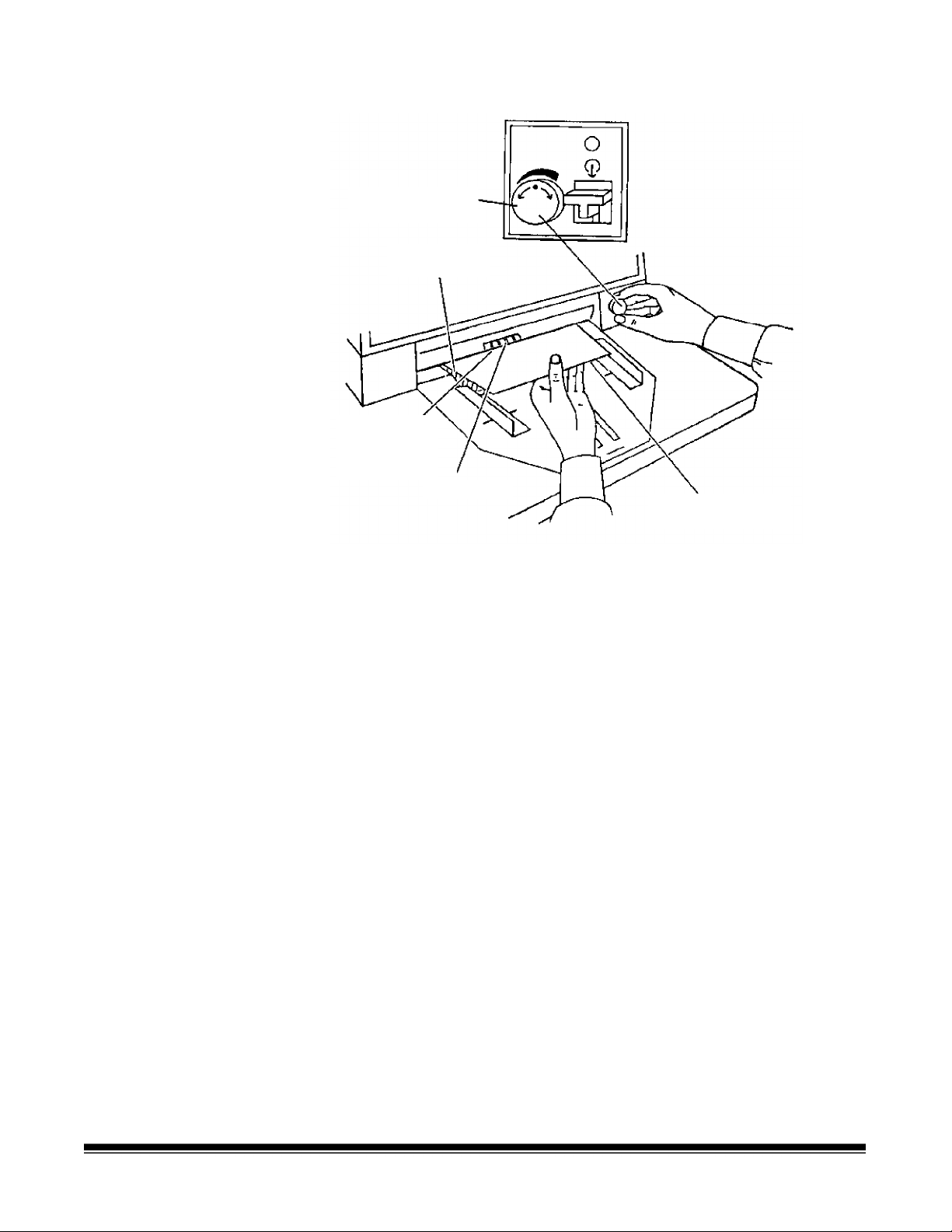
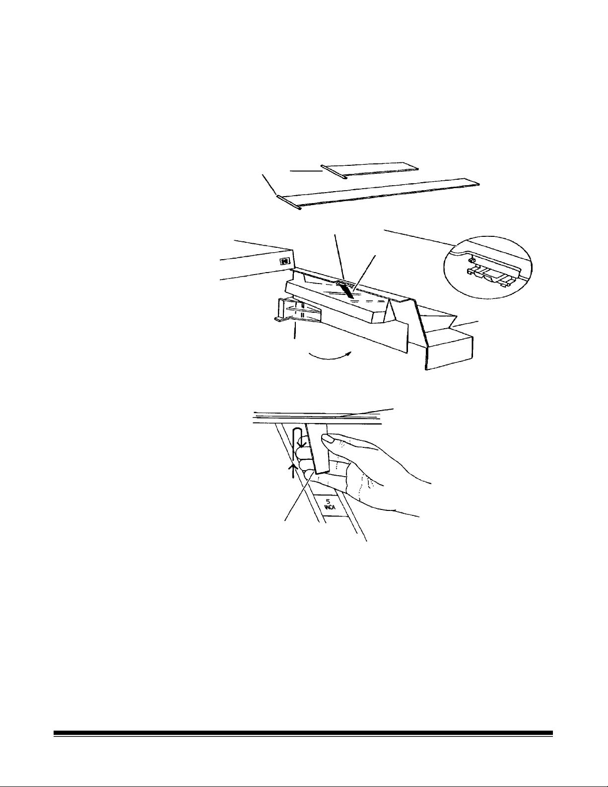
6. Turn the gap adjustment knob counterclockwise 2 1/2 turns.
Gap adjustment knob
Separated
document
Gap
(between feed
and separator
rollers)
Feed rollers
Trailing edge of top
document
7. Select two documents of the same size, texture and thickness,
similar to the types of documents you will be processing.
8. Place one document on top of the other. Hold the documents firmly
by their trailing edges. I nser t them into the gap approximately 1/8 in.
(3 mm).
If the documents separate, repeat the following steps until the
documents do not separate:
• Turn the gap adjustment knob clockwise 1/2 tur n.
• Insert the documents again.
If the documents do not separate, proceed with Step 9.
9. Rotate the gap adjustment knob counterclockwise 1 or 2 clicks.
10. Hold the trailing edges of the documents firm ly. Insert them into the
gap.
• If the bottom document is not separating from the top document ,
remove the documents and repeat Steps 9 and 10 until the
bottom document separates from the top document by
approximately 1 in. (25.4 mm).
• If the bottom document is separat ing from the top document,
proceed with Step 11.
A-61092 September 1999 2-5
Page 17
11. When you have adjusted the gap so the bottom document
g
separates consistently from the top document , rotate the gap
adjustment knob counterclockwise another 1 or 2 clicks to complete
the adjustment.
12. Feed a stack of 50 to 100 documents twice through the transport
system. Verify the final count reflects the total number of docum ents
fed and that the counter shows the same amount each time the
documents are counted.
If the count is not the same, the gap is not adjusted cor r ectly.
Rotate the gap adjustment knob counterclockwise another 1 or 2
clicks and repeat Step 12. Repeat until corrected.
13. Press Stop.
14. Enter function code F04 and disable Counting Only.
15. Press Enter.
Adjusting the feed
shelf position
automatic feeder only)
(semi-
Before you begin feeding documents into the scanner, adjust the
position of the feed shelf .
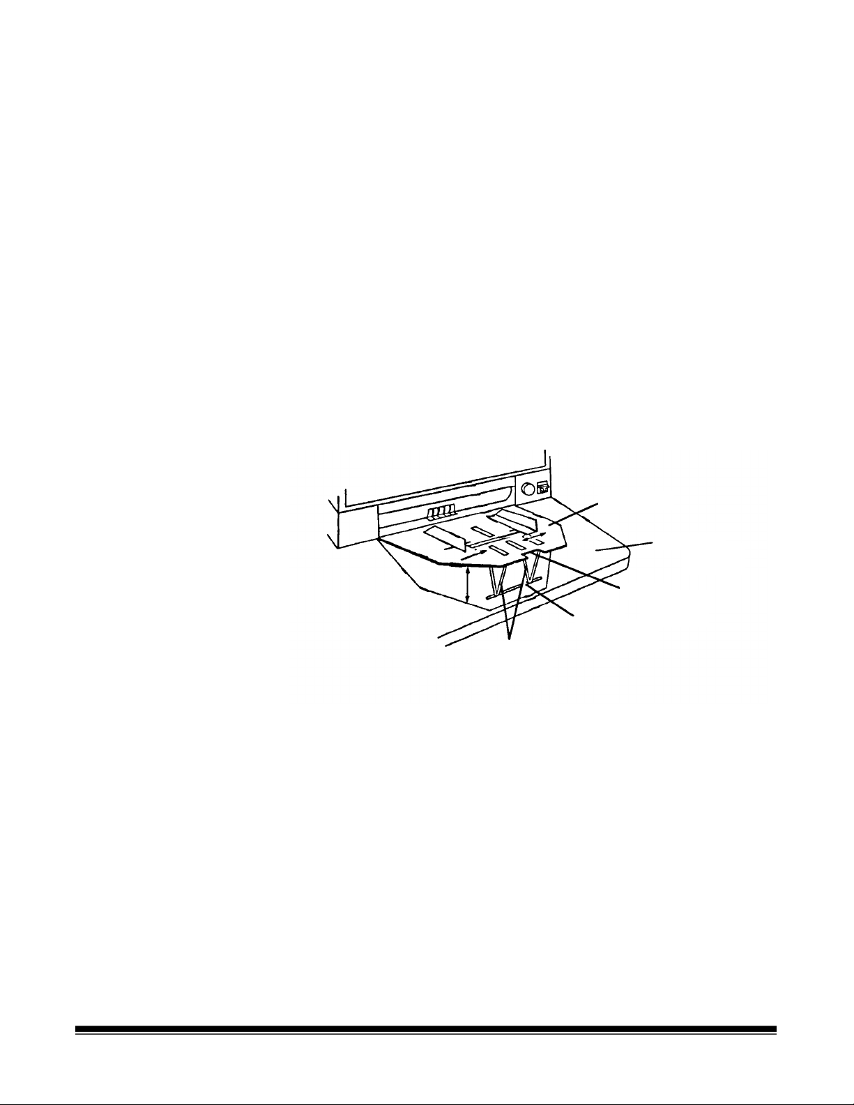
Feed shelf
Work shelf
Notch
Groove
Height
adjustment
le
s
To automatically feed multiple documents, the feed shelf should be in
the raised position (as shown above).
To raise the feed shelf:
1. Grasp the notch and lift the feed shelf.
2. Swing the height adjustment leg s out and insert them into the
groove on the work shelf.
To hand-feed documents (one at a time), the feed shelf should be in the
down position (not shown).
To lower the feed shelf:
1. Grasp the notch and lift the feed shelf until the height adjust m ent
legs are no longer resting in the groove on the work shelf.
2. Tuck the height adjustment legs in and lower the feed shelf into
position.
2-6 A-61092 September 1999
Page 18
Adjusting the feed
shelf side guides
(semi-automatic feeder
only)
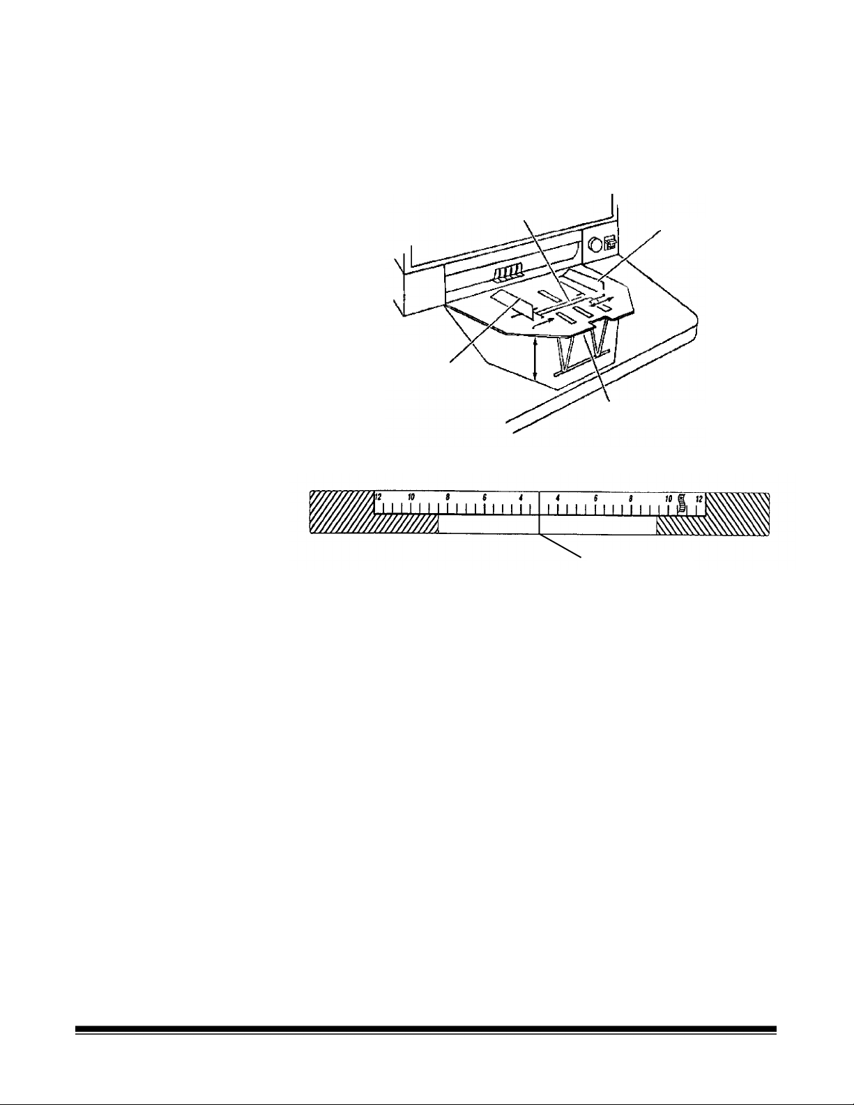
Before you begin processing documents, adj ust the side guides on the
feed shelf to accommodate the documents being processed.
1. Slide apart the side guides on the feed shelf unt il t he feed shelf
label is visible.
Feed shelf label
Side guide
Side guide
Feed shelf
Feed Shelf Label
Center line
2. Center the documents across the feed shelf label. Adjust the feeder
side guides dependent upon the width of the document. Leave
approximately 1/16 in. (2 mm) clearance on each side of the
documents so they feed properly.
NOTE: If the documents are larger than the area shown on the
feed shelf label and do not fit between the side guides,
rotate and reposition the documents within the side guides.
A-61092 September 1999 2-7
Page 19
Adjusting the exit
g
)
8 ½-inch (A5)
Checks
hopper side guides
and end stop
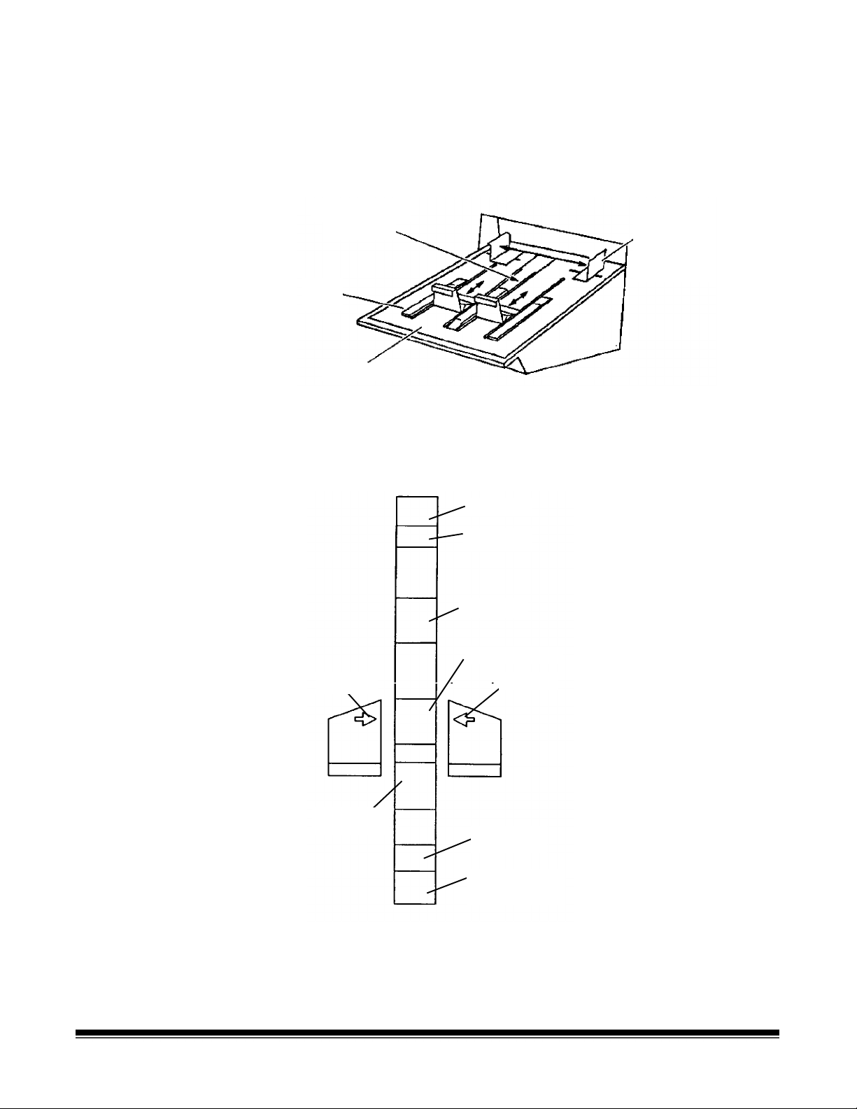
The exit hopper side guides and end stop must be adjust ed so
documents are stacked properly after processing.
1. Adjust the side guides on the exit hopper to mat c h the adjustment
of the side guides on the feed shelf.
Side
Exit hopper
label
End
stop
Exit hopper
guides
(arrows
depict correct
placement of
side
uides
2. Adjust the end stop of the exit hopper by deter m ining the longest
document to be processed. Slide the end stop until t he ar r ows point
to where the length of the longest document is shown on the exit
hopper label.
11-inch (A4)
IBM cards
5-inch
ArrowArrow
14-inch (B3)
17-inch with
adapter (A3)
2-8 A-61092 September 1999
Page 20
Changing the
Short document deflector
Long document deflector
Lip of exit hopper
deflector
The scanner comes with two deflectors (stored in the pocket located
inside the right-side access door), desig ned to help stack the
documents as they exit the transport system and enter the exit hopper.
Use the short deflector for documents less than 5 in. (13 cm) and the
long deflector for docum ents longer than 5 in. (13 cm) as well as for
mixed sizes.
Attachment pin
Holding clip
Deflector
Front cover
(does not have to
be open to attach
deflectors)
(Swings to right)
1. Grasp the deflector near t he at tachment pin (as shown).
(black side must be down)
Deflector
2. Guide the deflector into the exit hopper, just below the lip of the
hopper, to insert the attachment pin in the holding clip.
3. Pull the deflector toward you until it clicks into place.
A-61092 September 1999 2-9
Page 21

3 Operating the Scanner
Overview
This chapter provides instructions for selecting modes, using temporary
operating values and feeding documents using either the semiautomatic feeder or the aut om atic feeder.
The scanning process consists of the following steps:
1. Prepare the scanner for operation (r efer to Chapter 2,
Started
2. The scanner is enabled by the host system.
3. Select a mode for the application. Typically the host computer
performs this step, but it may also be performed by the operator.
4. Select temporary operating values (if r equired).
5. Press the Run key.
6. Feed documents into the transport (refer to
using the semi-automatic
• The scanner assigns a sequential ID number ( for digital image
• The document is scanned.
• The document image header is created.
• The host computer initiates tr ansfer of the document image
for more information.)
Feeding Documents
(or
automatic) feeder
storage), the document im age level and image address.
header and document image to the host system for storage on
magnetic or optical disk media.
later in this chapter).
Getting
• Documents are deposited in the exit hopper, face down, in the
order in which they were fed into the transport.
7. Press the Stop key.
8. Press P2 or enter function code F38 to indicat e end- of-job.
9. Turn off the side panel switch.
NOTE: If the scanner will not be used for 8 hours or more, tur n off
the main power switch.
A-61092 September 1999 3-1
Page 22

Selecting a mode
The scanner offers 18 modes that m ay be programmed for a particular
application or group of applications.
The modes are programmed at the time of installation and stored f or
easy access and use.
Typically, the mode is selected via the host system, using a scannerunique command. However, you may manually select a mode.
To select a mode, do the following:
1. Enter function code F01 (Select Mode) by pressing the F key and
the numeric keys 0 and 1.
2. Press Enter.
3. Enter the desired mode number (modes r ange from 1 to 18).
4. Press Enter.
You can also check with your system administ r at or to see if one or
more of the P keys has been preprogrammed to perform specific
functions.
Temporary operating values
Each of the 18 modes programm ed at the time of installation contain
definitions that affect t he output of the scanner. Each mode is
programmed to confor m to the output requirements of a particular
application or group of applications.
There may be instances, however, when a particular application
requires some variation of an existing mode. In such instances, mode
definitions may be changed using available function codes. See
Chapter 4,
available function codes.
NOTE: Changes to mode definitions remain in effect until another mode
Example:
If mode 15 contains definitions t hat allow you to use the
Imagelink
from the leading edge of the document the endorsement is printed) is
programmed to be 0.5.
Function Codes,
is selected or the side panel switch is turned off. The original
mode definition is only affected by these changes if the mode
overrides are saved (the mode override option may be select ed
at installation and if selected, a plus sign (+) appear s in t he first
line of the status display).
Endorser, the starting print position (which defines how far
for a listing and descriptions of the
Kodak
If there is a special application that r equires the endorsement be printed
1 inch from the leading edge of the document, you may use function
code F59 to temporarily change the starting pr int position.
3-2 A-61092 September 1999
Page 23
Feeding documents
using the semiautomatic feeder
Following are document feeding instruct ions using the semi-automatic
feeder. After the scanner has been prepared for operat ion, the desired
mode and any temporary operating values have been defined, you are
ready to feed documents into the transport.
1. Verify the side panel switch is on and that any adjustments have
been made (feeder side guides, exit hopper side guides, etc.).
2. Press Run.
3. Select a stack of documents that is no m or e than 0.75 in. (19 mm)
thick.
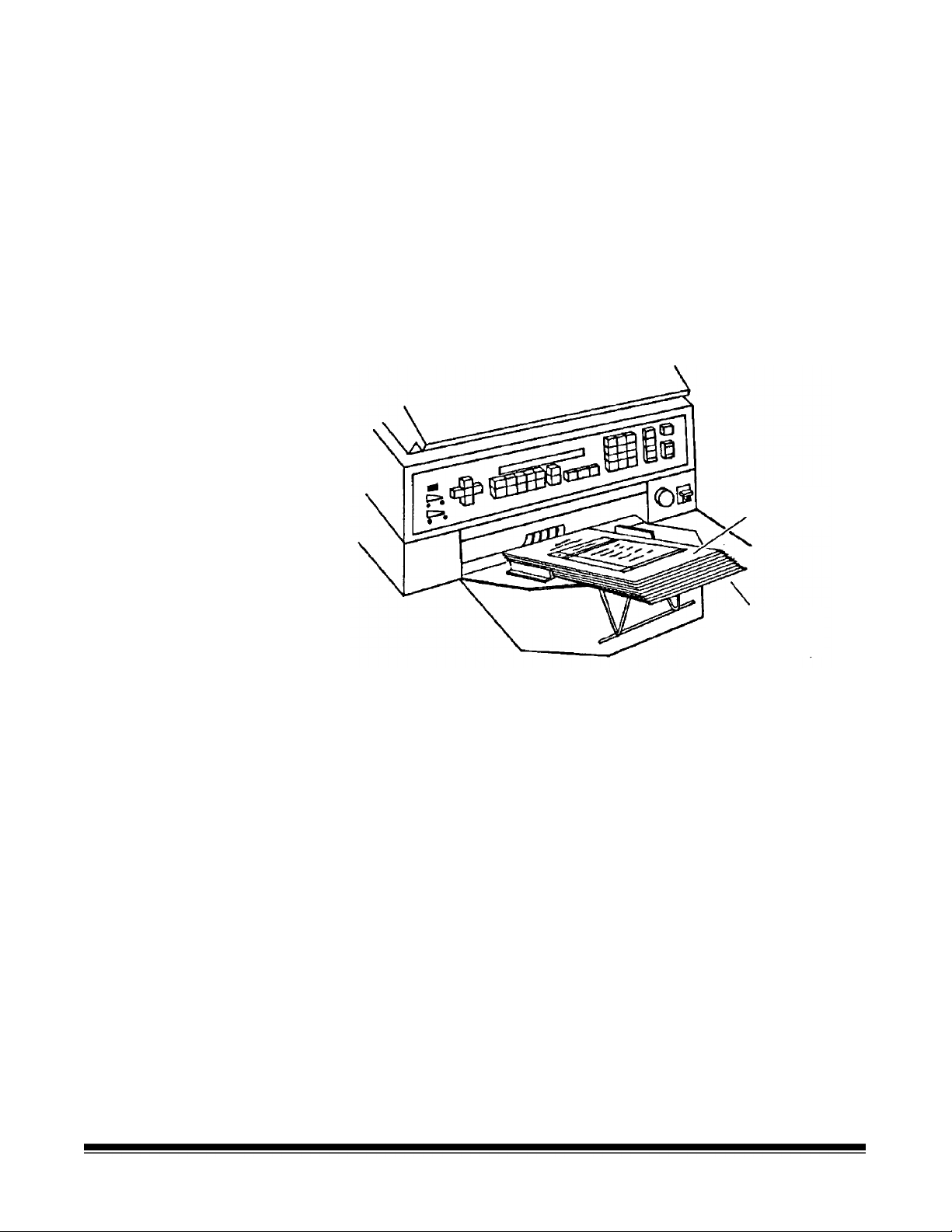
4. Fan the stack of documents so the leading edge of the top
document engages the feed and separat or r oller s as shown:
Top
document
Fanned
documents
5. Place the stack of fanned documents into the feeder so the leading
edge of the top document contacts t he feed and separator rollers.
The documents are drawn into the transport, with the t op docum ent
being fed first. The documents are deposited in the exit hopper
face down, in the order in which they were fed into the transport .
6. Repeat Steps 3 through 5 until all of the application documents
have been fed into the transport.
7. Press Stop after all documents have been deposited in the exit
hopper.
A-61092 September 1999 3-3
Page 24
Feeding thick
)
documents
The gap release lever is used to feed thick documents such as card
stock or cover stock. The lever is located on the front panel of the
scanner, next to the gap adjustment knob.
(Graphic depicts movement
of separator rollers when
lever is used
(Graphic depicts gap
adjustment)
Gap
release
lever
1. Press down and hold the gap release lever. This opens the gap
between the feed and separator rollers, allowing thick docum ents t o
pass between them. You will be able to see the gap open as the
lever is pushed down.
2. Insert the thick docum ent past t he rollers until it is taken into the
transport system.
NOTE: If more than one t hick docum ent is to be scanned, feed
them into the transport one at a time.
Gap release
lever
Feed roller
(hold down)
Gap
Separator
roller
Thick
document
3. After the thick document(s) have been scanned, release the gap
release lever; it will return to its orig inal position. The feed and
separator rollers will return to t heir pr eviously adjusted positions.
3-4 A-61092 September 1999
Page 25

Feeding documents using the automatic feeder
Following are document feeding instruct ions using the automatic
feeder. After the scanner has been prepared for operat ion, the desired
mode and any temporary operating values have been defined, you are
ready to feed documents into the transport.
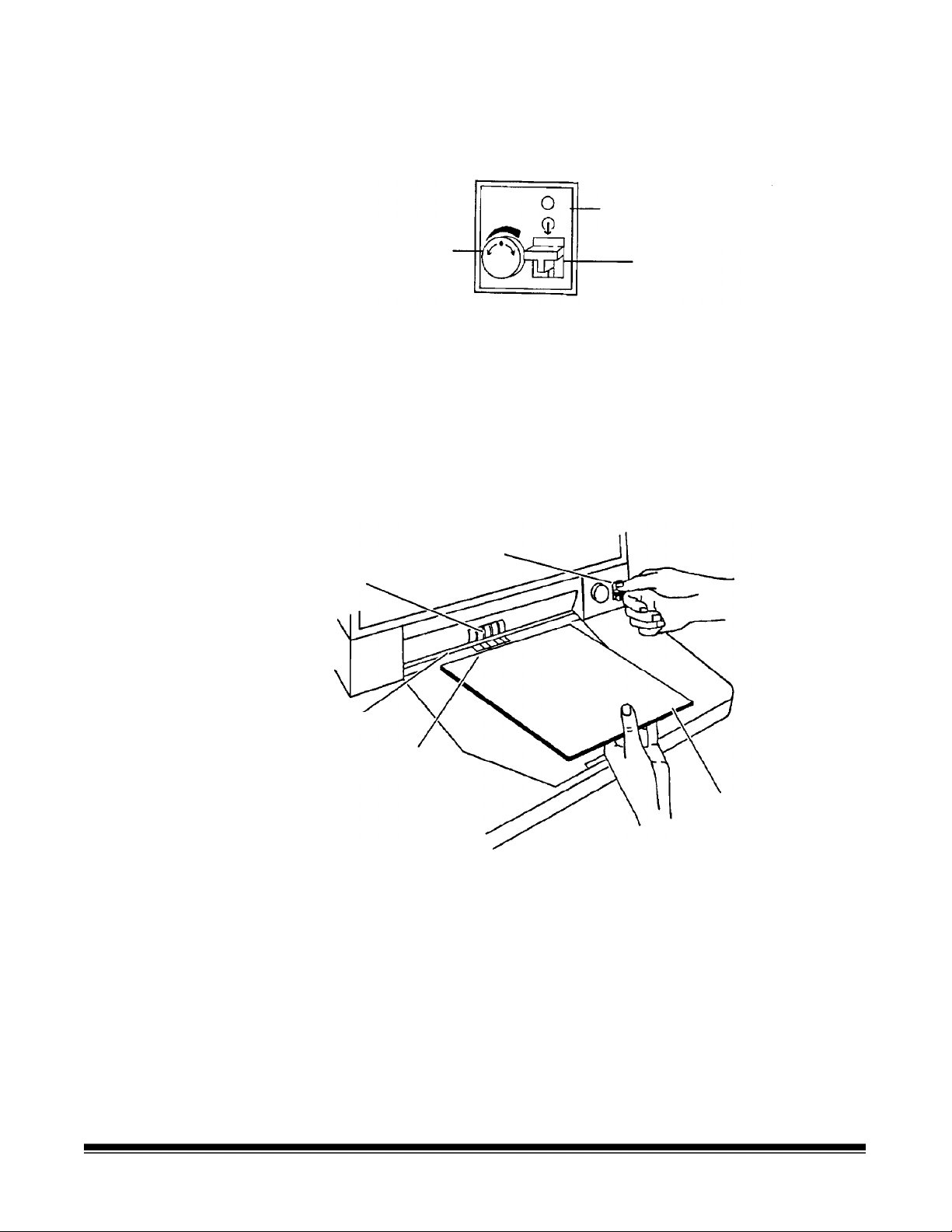
1. Verify that the power is on and that any adjustments have been
made (feeder side guides, exit hopper side guides, etc.).
2. Select a stack of documents that is no more than 1.5 in. (38 mm)
thick. Hold the stack with the front sides f acing up and the top of the
documents facing toward the scanner. Tap the top edge of the stack
against a flat surface so the documents are in an even bundle.
3. Fan the stack of documents so the leading edge of the t op
document sticks out the farthest.
4. Lift the feeder module up and slide the leading edge of t he
document underneath the feeder module. To help prevent multiple
feeds, place the stack of documents under t he f eeder m odule and
pull the stack back slightly (about ¼-inch) from the separator roller.
5. Press Run.
NOTE: Be sure the documents are center-fed so each document
covers the 3 ½-inch required width.
6. As you scan documents, set the image level, as r equir ed, and
periodically remove documents from the exit hopper.
7. Repeat Steps 2 through 4 until all of t he applicat ion documents
have been fed into the transport.
8. Press Stop after all documents have been deposited in the exit
hopper.
A-61092 September 1999 3-5
Page 26

4 Function Codes
Using function codes
There are a variety of functions available which may be used to
temporarily change operating param et ers, and to obtain system
and accessory status information.
These functions are listed in the Function Code Sum m ar y later in t his
chapter. Following are the procedures for using function codes:
1. Press the F key.
2. Press the numeric keys which correspond to the desired function
code.
3. Press Enter.
If the function is used to enable or disable an operation (turn an option
on or off):
1. Press 1 to turn the option On, or 0 to turn the option Off.
2. Press Enter.
If the function requires numeric input:
1. Press the numeric key(s) requir ed.
2. Press Enter.
If the function is used to incr ement or decrement a measurement or
setting:
• Press the arrow keys to increment or decrem ent as follows:
− Press the Up arrow to increment the measurement by
1 inch (25 mm) or one value, or
− Press the Down arrow to decrement t he m easur ement by
1 inch (25 mm) or one value, or
− Press the Right arrow to increment the measurement by
1/8-inch (3 mm) or one value, or
− Press the Left arrow to decrement the measurement by
1/8-inch (3 mm) or one value.
• Press Enter.
To cancel a function (befor e pr essing Enter ) or clear the status display
after executing a funct ion code:
• Press C (Clear/Cancel).
A-61092 September 1999 4-1
Page 27

Function code summary
Following is a summary of the functions and their cor r esponding
function code:
Status
Accessory Status*...............................................................F05
Date and Time Display* ‡ ...................................................F23
Elapsed Time* ....................................................................F17
Counters
Level 0 Count*....................................................................F10
Level 1 Count*....................................................................F11
Level 2 Count*....................................................................F12
Level 3 Count*....................................................................F13
Total Document Count*.......................................................F09
Reset Level Counts.............................................................F14
Setup
Action/Confirmation Tone ‡.................................................F93
Alarm Tone ‡......................................................................F16
Alarm Volume.....................................................................F15
Change Date ‡....................................................................F22
Change Time ‡...................................................................F21
Display Contrast..................................................................F18
Display Language...............................................................F19
Measurement System.........................................................F20
Operator ID.........................................................................F34
Scanner Calibration............................................................F37
Mode
Select Mode........................................................................F01
Select Linked Mode ............................................................F91
Counting Only..................................................................... F04
Restore Mode .....................................................................F02
Index/Image Address
Last Image Address*...........................................................F08
Level 0*...............................................................................F07
Level 1*...............................................................................F94
Level 2*...............................................................................F95
Level 3*...............................................................................F96
Fixed Field..........................................................................F92
Next Image Address ...........................................................F97
* May be executed while transport is running.
‡ Available when using advanced capabilities.
4-2 A-61092 September 1999
Page 28

Operation
Run..................................................................................... F99
Terminate Batch*................................................................F06
Stop* ...................................................................................F98
Scanning
Scanner Calibration............................................................F37
Latched Scanning Flag*......................................................F73
Momentary Scanning Flag*.................................................F74
Scanner End-of-Job............................................................F38
Endorser
Endorser On/Off..................................................................F57
Endorser Mode...................................................................F58
Endorser Print Position .......................................................F59
Footswitch
Footswitch Confirmation Tone ‡..........................................F75
Bar Code‡
Bar Code Reading On/Off...................................................F60
Partial Bar Code Reading On/Off........................................F66
Bar Code Reading Confirmation Tone................................F63
Bar Code/Patch Reading Confirmation Tone......................F62
Bar Code Test.....................................................................F65
Omit Bar Code Reading on Next Document*......................F64
Document Controller
Length Checking On/Off.....................................................F70
Omit Length Checking on Next Document Only*................F71
Skew Detection...................................................................F72
Document Printers
All Document Printers On/Off..............................................F40
Primary Document Printer 1 On/Off ....................................F41
Secondary Document Printer 1 On/Off ‡.............................F42
Document Printer 12 On/Off ...............................................F43
Omit Printing on Next Document.........................................F44
Print Position.......................................................................F46
Print Test............................................................................F45
Printer Character Shift ........................................................F39
Printer Open Jet Test..........................................................F56
Purge Frequency................................................................F49
Purge Print Head*...............................................................F48
* May be executed while transport is running.
‡ Available when using advanced capabilities.
A-61092 September 1999 4-3
Page 29

Super12 Document Printer
Print Contrast......................................................................F39
Print Head Position.............................................................F40
Print Test............................................................................F45
Automatic Purge Print Head ...............................................F48
Align Print Image*............................................................... F49
Print Cartridge Status .........................................................F56
NOTE: Function codes F43 and F44 work the same on a
Super12 Document Printer.
Patch Reader
Patch Reader 1 On/Off ....................................................... F50
Patch Reader 2 On/Off ‡ .................................................... F51
End Fed Patch Reading On/Off ‡ .......................................F52
Patch Reading Confirmation Tone ‡...................................F53
Omit Patch Reading on Next Document*............................F54
* May be executed while transport is running.
‡ Available when using advanced capabilities.
4-4 A-61092 September 1999
Page 30

Function code listing
Following is a listing of the function codes and descr ipt ions.
Code Function Code Name Description
F01 Select Mode Allows you to select one of the predefined application
modes. Enter a value from 1 to 18 and press Ent er .
F02 Restore Mode Allows you to restore the current application mode to its
default status, provided mode overrides are not saved.
F04 Counting Only
Allows you to count the number of documents entering
the scanner without scanning. Enter 1 to t ur n Count ing
Only on, or 0 to turn Counting Only off and press Enter.
F05 Accessory Status Displays the current status of each accessor y installed.
Press the Down arrow to view the status of the next
accessory, or press the Up arrow to view the status of the
previous accessory.
F06 Terminate Batch Allows you to prematurely end a batch.
F07 Level 0 Allows you to define the next document scanned as a
Level 0 document.
F08 Last Image Address Allows you to display the image address of the last
document scanned.
F09 Total Document Count
Allows you to display the total number of documents that
entered the feeder (Level 3, Level 2, Level 1 or Level 0).
Press 0 to reset the counter and then press Ent er .
F10 Level 0 Count Allows you to display the total number of documents that
have entered the feeder as Level 0 documents. Press 0 to
reset the counter and then press Ent er .
F11 Level 1 Count Allows you to display the total number of documents that
have entered the feeder as Level 1 documents. Press 0 to
reset the counter and then press Ent er .
F12 Level 2 Count Allows you to display the total number of documents that
have entered the feeder as Level 2 documents. Press 0 to
reset the counter and then press Ent er .
F13 Level 3 Count Allows you to display the total number of documents that
have entered the feeder as Level 3 documents. Press 0 to
reset the counter and then press Ent er .
F14 Reset Level Counts
Allows you to reset all the level counters (Level 0, Level 1,
Level 2, and Level 3) to 0.
F15 Alarm Volume Allows you to adjust the volume of the alarm. Pr ess the
Up arrow to increase the volume or press the Down
arrow to decrease the volume, then press Enter.
F16 Alarm Tone Allows you to adjust the pitch of the alarm t one. Pr ess the
Up arrow to increase the pitch or press the Down arrow
to decrease the pitch, then press Ent er.
A-61092 September 1999 4-5
Page 31

Code Function Code Name Description
F17 Elapsed Time Allows you to display the number of hours the motor,
transport and main power have been running, in addition
to the non-resettable document count. Press the Right
arrow to view the meters.
Meter A — displays motor-on hours
Meter B — displays transport-on hours
Meter C — displays main power-on hours
Meter D — displays document count
F18 Display Contrast Allows you to adjust the contrast of the status display.
Press the Up arrow to increase the contrast or press t he
Down arrow to decrease the contrast, then press Enter.
F19 Display Language Allows you to choose your preferred language. Press the
arrow key to toggle between two available options.
F20 Measurement System Allows you to choose your preferred measurement
system. Press the arrow key to togg le bet ween two
available options.
F21 Change Time Allows you to change the time. Enter the new time in the
format illustrated and pr ess Ent er .
F22 Change Date Allows you to change the date. Enter the new date in the
format illustrated and pr ess Ent er .
F23 Time and Date Display Allows you to view the current time and date.
F34 Operator ID Number Allows you to display the current operator ID number
and/or change to a new operator ID number. Enter a new
operator ID up to 3 digits and press Ent er .
F37 Scanner Calibration Allows you to initiate the calibration process requir ed
before scanning documents. T o do this, feed a calibration
target into the scanner.
F38 Scanner End-of-Job Allows you to signal the host computer that t he last
document of the job has been f ed int o the transport.
F39 Printer Character Shif t
(for Document Print er 12)
Allows you to select which set of ink jets will be used to
print each character. Enter 1 to select the left set of ink
jets, enter 2 to select the cent er set of ink jets, or enter 3
to select the right set of ink jets, then press Ente r.
F39 Print Contrast
(for Super12 Document
Printer)
Allows you to increase or decrease the amount of ink put
on the document. Press the Up arrow for more ink and
press the Down arrow for less ink. Incremental values
are: 12, 25, 37, 50, 62, 75, 87 and 100%.
4-6 A-61092 September 1999
Page 32

Code Function Code Name Description
F40 All Document Printers
On/Off
(for Document Print er s 1
Allows you to turn all Document Printers (primary DP1,
secondary DP1 and DP12) on or off. Enter 1 to turn on or
0 to turn off, then pr ess Ente r .
and 12)
F40 Print Head Position
(for Super12 Document
Printer)
Allows you to change the print heads or clean the printer.
This function can only be performed when the tr ansport is
off. Enter 1 to Change Heads or 2 to Clean Printer, then
press Enter.
F41 Primary DP1 On/Off Allows you to turn the primar y Document Printer 1 on or
off. Enter 1 to turn on or 0 to turn off, then press Enter.
NOTE: If the Super12 Document Printer is inst alled, a
message indicating “Unassigned Function” will be
displayed.
F42 Secondary DP1 On/Off Allows you to turn the secondary Document Printer 1 on
or off. Enter 1 to turn on or 0 to turn off, then press Enter .
NOTE: If the Super12 Document Printer is installed, a
message indicating “Unassigned Function” will be
displayed.
F43 Document Printer 12/
Super12 On/Off
Allows you to turn the Document Printer 12 or Super 12
Document Printer on or of f. Enter 1 to turn on or 0 to turn
off, then press Enter.
F44 Omit Printing on the Next
Document Only
Allows you to specify no information be printed on the
next document scanned. Printing will resume on
subsequent documents. Enter 1 to omit printing on the
next document, or enter 0 to print on t he next docum ent
then press Enter.
NOTE: If you enter F44 and then F45, the Omit Printing
Status on Next Document will be cleared.
F45 Print Test (for Document
Printers 1 and 12)
Allows you to test the position and print quality of all
Document Printers installed. Enter t he number of the print
test you want to perform.
1=Print IA test 3=Shift test
2=Prime test 4=Standard test
This function can be done when the transport is off.
F45 Print Test
(for Super12 Document
Printer)
Allows you to test the position and print quality of the
Super12 Document Printer. Enter the number of the print
test you want to perform.
1=Mode Image — will print the current image for the level
and mode you are in.
2=Test Pattern — will print a preloaded test image.
This function can be done when the transport is off.
NOTE: If you enter F44 and then F45, the Omit Printing
Status on Next Document will be cleared.
A-61092 September 1999 4-7
Page 33

Code Function Code Name Description
F46 Print Position Allows you to specify how far from t he leading edge of the
document printed informat ion will appear. Press the Up
arrow to increment the starting print position by 1 inch
(25 mm), press the Down arrow to decrement the starting
print position by 1 inch (25 mm). Press the Right arrow to
increment the starting print position by 0.125-inch (3 mm),
or press the Left arrow to decrement the st ar ting print
position by 0.125-inch (3 mm), then press Enter.
F48 Purge Print Pattern
Allows you to initiate an immediate priming ink spurt.
(for Document Print er s 1
and 12)
F48 Print Purge Head
(for Super12 Document
Printer)
F49 Purge Frequency
(for Document Print er 1
and 12)
Allows you to initiate an automatic purging of the print
heads.
This function can be done when the transport is off.
Allows you to specify how often, in terms of the num ber of
documents fed into the transpor t, a priming ink spurt is
initiated. Enter the number of documents, up to 50,000
and press Enter.
F49 Align Print Image
(for Super12 Document
Printer)
Allows you to specify how far to move the left half of an
image up or down (in increments of one line) on t he
document so it will align with the right half of the image.
F50 Patch Reader 1 On/Off Allows you to turn the pr im ary Patch Reader on or off.
Enter 1 to turn on or 0 to turn off, then press Enter.
F51 Patch Reader 2 On/Off Allows you to turn the secondar y Patch Reader on or off.
Enter 1 to turn on or 0 to turn off, then press Enter.
F52 End Fed Patch Reading
On/Off
Turn End Fed Patch Reading on if you expect the patch t o
be located in the vertical (vs. horizontal) position on the
document. Enter 1 to turn on or 0 to turn off, then press
Enter.
F53 Patch Reading
Confirmation Tone On/Off
Allows you to turn the confirmation tone on or off which
informs you when the Patch Reader has successfully read
a patch document. Enter 1 to turn on or 0 to turn off, then
press Enter.
F56 Printer Open Jet Test
(for Document Print er s 1
and 12)
Allows you to determine whether or not there are
nonfunctional ink jets in the Super 12 Document Printer
ink cartridge. Press C to return to a norm al oper ating
display.
F56 Printer Cartridge St atus
(for Super12 Document
Printer)
Allows you to determine whether or not there are
nonfunctional ink jets in the Super 12 Docum ent Printer.
Also checks the print head(s) connection to t he flex cable
to assure the print heads(s) are installed properly. Press
C to return to a normal oper at ing display.
F57 Endorser On/Off
Allows you to turn the Endorser on or off. Enter 1 to turn
on or 0 to turn off, t hen pr ess Ent er.
4-8 A-61092 September 1999
Page 34

Code Function Code Name Description
F58 Endorser Mode Allows you to display the current Endorser mode and/or
change the Endorser mode. To chang e to Endorser
mode, press any arrow key to toggle between the two
available options and then press Enter.
F59 Endorser Print Position Allows you to specify how far from the leading edge of the
document the endorsement will appear. Press the Up
arrow to increment the starting print position by 1 inch
(25 mm), press the Down arrow to decrement the starting
print position by 1 inch (25 mm). Press the Right arrow to
increment the starting print position by 0.125-inch (3 mm),
or press the Left arrow to decrement the st ar ting print
position by 0.125-inch (3 mm), then press Enter.
F60 Bar Code Reading 1
On/Off
F62 Bar Code/Patch Reading
Confirmation Tone
Allows you to turn bar code reading on or off . Enter 1 to
turn on or 0 to turn off and then press Enter.
Allows you to turn the bar code/patch reading
confirmation tone on or of f. Enter 1 to turn on or 0 to turn
off and then press Ente r.
F63 Bar Code Reader
Confirmation Tone
Allows you to turn the confirmation tone on or off which
informs you when the Bar Code Reader has successfully
read a bar code document. Enter 1 to turn on or 0 to turn
off and then press Ente r.
F64 Omit Bar Code Reading on
the Next Document Only
Allows you to omit bar code reading on the next document
scanned. Bar Code Reading will resume on subsequent
documents. Enter 1 to turn on or 0 to turn off, then press
Enter.
F65 Bar Code Test
Allows you to perform a test to verify the operat ion of the
Bar Code Reader. Enter the number of the bar code test
you want to perform: 1=Evaluate; 2=Display; 3=%Kodak;
or 4=%Norm, then press Enter.
F66 Partial Bar Code Reading
On/Off
Allows you to turn partial bar code reading on or off. Enter
1 if you want the scanner to read bar codes with a start
character (and
n
characters beyond the start character
that can be read) even if no end character is encountered.
Enter 0 to turn off par tial bar code reading off, then press
Enter.
F70 Length Checking On/Off Allows you to turn length checking on or off which
monitors the length of t he document(s) scanned using
predefined maximum allowable lengths. Enter 1 to turn on
or 0 to turn off and then press Enter.
F71 Omit Length Checking on
the Next Document Only
Allows you to omit length checking on the next document
scanned. Length monitoring will resume on subseq uent
documents. Enter 1 to turn on or 0 to turn off, then pr ess
Enter.
A-61092 September 1999 4-9
Page 35

Code Function Code Name Description
F72 Skew Detection Allows you to turn skew detection on or off which monitors
the amount of skew using predefined skew angle(s).
Enter 1 to turn on or 0 to turn off, then press Enter.
F73 Latched Scanning Flag Allows you to set a flag in the image headers which alerts
the host system that this document, and those which
follow, are of special interest . The flag will remain
activated for every document until it is turned off. Enter 1
to turn on or 0 to turn off, then press Enter.
F74 Momentary Scanning Flag Allows you to set a flag in the image header which alerts
the host system that this document is of special interest.
This flag is set only for t hat one document. Enter 1 to turn
the momentary scanning flag on, then press Enter.
F75 Footswitch Confirmation
Tone
Allows you to turn the confirmation tone on or off which
informs you when the Footswitch is pressed and/or
released. Enter 1 to turn on or 0 to turn off, then press
Enter.
F91 Select Linked Mode Allows you to switch from one application mode to
another, keeping the last im age address. Enter the
number of the application mode you wish to select, then
press Enter.
F92 Fixed Field Allows you to enter a new fixed field value containing
alphanumeric characters.
NOTE: If the fixed field width for t he mode you are using
is 0, and E104 error will be displayed. To correct
this, change to a mode that has a fixed field or
modify the mode you are using so the fixed f ield
is not 0.
F93 Action/Confirmation Tone Allows you to hear the pitch of the alarm tone.
F94 Level 1 Allows you to assign Level 1 to the next document fed into
the transport.
F95 Level 2 Allows you to assign Level 2 to the next document fed into
the transport.
F96 Level 3 Allows you to assign Level 3 to the next document fed into
the transport.
F97 Next Image Address Allows you to input the next image address. Enter the
next image address, then press Enter.
F98 Stop Allows you to stop the transport.
F99 Run Allows you to turn on the tr anspor t .
4-10 A-61092 September 1999
Page 36

5 Maintenance
Cleaning tasks
Cleaning materials
To keep your scanner in good operating condition, the following tasks
should be performed:
• Cleaning the imaging g uides (daily)
• Cleaning the feed and separator roller ( sem i- automatic feeder)
(daily)
• Cleaning the feeder module and separator r oller ( aut omatic feeder)
(daily)
• Cleaning the paper path (daily)
• Vacuuming inside the scanner (daily)
• Cleaning the exposure lamp housings (weekly)
• Cleaning the cabinet (weekly)
• Cleaning the air filter (monthly)
For additional maintenance and feeder adjust m ent information, see
Kodak publication A-61604. This publication is part of the Maintenance
and Feeder Adjustment procedure video; Catalog Number 828 5306.
Materials needed to perform maintenance procedur es ar e:
• A mild cleaning agent
• A quality lens cleaner
• A soft, clean, lint-free cloth
• A soft-bristled cleaning brush
• A vacuum cleaner
• Staticide Wipes
• Roller Cleaning Pads
• Paper Path Cleaner
IMPORTANT:
Replacement parts
A-61092 September 1999 5-1
Consumable parts that can be replaced by the customer include:
• Air filter
• Exposure lamps
• Imaging guides
• Automatic Document Feeder Module
• Automatic Document Feeder Separator Roller
Instructions on how to replace these parts are included later in this
chapter.
Do not use any unauthorized commercial cleaning
solvent in any of the cleaning procedures.
Page 37

Daily maintenance procedures
Maintenance procedures that should be performed daily include
cleaning the imaging guides, the feed and separator rollers, the paper
path and vacuuming inside the scanner.
Cleaning the imaging guides
To clean the imag ing guides, follow the steps below:
IMPORTANT:
1. Open the right-side access door.
NOTE: The illustr ation below shows the rear view of the scanner.
Upper lamp
housing assembly
Upper imaging guide
Lower image guide
Do not use any abrasive materials when cleaning the
imaging guides. This includes abrasive cleansers,
commercial solvents, paper towels, or coarse clot hs.
Lower lamp housing
assembly
Upper imaging guide
Lower imaging guide
2. Locate and grasp the end of the upper im aging guide. Carefully
slide the imaging guide out of its track.
3. Locate and grasp the end of t he lower imaging guide. Caref ully
slide the imaging guide out of its track.
Right-side access door
5-2 A-61092 September 1999
Page 38

4. Remove dust from the imaging guides, using a soft bristle brush.
5. Remove fingerprints or smudges fr om t he imaging guides, wiping
both sides of each imaging guide with a clean, soft, lint-free cloth
slightly moistened with water or lens cleaner. Then, lightly wipe
both sides of each imaging g uide with a dry cloth or an antistatic
wipe.
IMPORTANT:
Do not use cleaning pads on the imaging guides. Do
not use any abrasive materials when cleaning the
guides. This includes abrasive cleansers, commercial
solvents, paper towels, or course cloths.
6. Remove the upper lamp housing assembly.
7. Remove dust from the upper lamp housing assem bly, using a soft
bristle brush.
8. Reinstall the upper lamp housing assembly.
Repeat Steps 6 thr ough 8 for the lower lamp housing assembly.
IMPORTANT:
Use care when handling the imaging guides. Hold
the imaging guides by the green handles only.
9. Grasp and hold the lower imaging guide by the g r een handle and
carefully slide it back into place. Make sure the grooves fully
engage the track.
10. Grasp and hold the upper imaging guide by the green handle and
carefully slide it back into place. Make sure the grooves fully
engage the track.
NOTE: The imaging guides ar e not interchangeable. They can
only be inserted one way.
11. Close the right-side access door.
A-61092 September 1999 5-3
Page 39

Cleaning the feed and
separator rollers (semiautomatic feeder)
Clean the feed and separator rollers at least twice a day to prevent ink,
toner, and dust from collecting on the rollers and preventing docum ents
from separating.
1. Grasp the front cover and swing it open to the right.
Roller cover
Release lever
Feed roller
Separator roller
2. Push the roller cover release lever toward the back of t he m achine.
3. Grasp and rotate the roller cover toward the back of the machine,
exposing the feed and separator rollers.
Roller assembly
Feed roller
Separator roller
4. Hold the feed and separator rollers and scrub them with a roller
cleaning pad until all residue is removed from t he roller ribs. Clean
the five small normal for c e r oller s ( below the feed roller — not
shown in this illustration) in the same manner.
5. Wipe the feed and separator rollers and the five normal f or c e r oller s
with a clean, dry, lint-free cloth to dry the rollers.
6. Rotate the roller assembly back into posit ion.
7. Close the front cover.
5-4 A-61092 September 1999
Page 40

Cleaning the feeder
module and separator
roller (automatic feeder)
Clean the feeder module and separator r oller daily to pr event ink, toner,
and dust from collecting on t he r ollers and preventing documents from
separating.
Cleaning the feeder module and separator roller:
1. O pen the front cover.
2. Push the roller cover release lever toward the back of t he m achine.
3. Grasp and rotate the roller cover toward the back of the machine,
exposing the feeder module and separator roller.
Roller cover
release lever
Roller cover
Feeder
module
4. Remove the feeder module by pushing it t o the right and lifting it out
of its position.
5. Clean both rollers of the f eeder module.
6. Replace the feeder module, by aligning the pins and fitting it into
position.
A-61092 September 1999 5-5
Page 41

Cleaning the separator roller:
1. O pen the front cover.
2. Push the roller cover release lever toward the back of t he m achine.
3. Grasp and rotate the roller cover toward the back of the machine,
exposing the feeder module and separator roller.
Roller cover
release lever
Roller cover
Feeder module
4. Lift and remove the separator roller cover plate.
5. Lift the separator roller out of the grooved brackets.
Separator roller
Grooved brackets
6. Clean the separator roller. Inspect the roller any areas where the
white foam is showing through the roller cover. If the roller shows
signs of wear, obtain and replace the separator roller.
7. Replace the separator roller by aligning t he pins in t he grooved
brackets.
8. Reinsert the separator roller cover plate.
9. Close the feeder cover.
10. Close the front door.
5-6 A-61092 September 1999
Page 42

Cleaning the paper path
NOTE: Before doing the following procedur e, clean the machine
thoroughly and use the roller cleaning pads to clean the f eed,
separator and normal force rollers — star t with a clean
machine.
Use the Paper Path Cleaner to clean the paper path rollers . Per iodically
feed a cleaning sheet with the gum side up thr ough the machine in both
the portrait and landscape orientation.
The paper path should be cleaned twice a day. Before you clean the
paper path, be sure the feed and separator rollers and imaging guides
have been cleaned.
1. To ensure complete coverage of the transport and norm al force
rollers, feed the cleaning sheet in t he center, and to the left and
right of the f eeder docum ent guides.
2. Repeat the procedure until no furt her r esidue is picked up by the
cleaning sheet.
3. Using a clean Paper Path Cleaner sheet, repeat Step 1 to verify that
the rollers are clean.
4. Turn the gum side down, and repeat Steps 1 through 3.
NOTE: When t he gum side is down, it may be necessary to hold
down the gap release lever to allow the Paper Path Cleaner
sheet to feed past the separator roller.
Vacuuming inside the scanner
Regular use of Paper Path Cleaner sheets m ay result in fewer major
cleanings with the roller cleaning pads.
NOTE: If t her e ar e feeder errors after cleaning the feed and separator
rollers, refer to the sect ion ent it led “Adjusting the feed and
separator roller gap”, in Chapter 2.
The sensors located under the horizontal plate in the f eeder/horizontal
transport area and in the upper section of the lower roller housing
assembly, the exposure lamp housings, and the air filter should be
vacuumed or wiped down thoroughly with a clean, dry, soft, lint-free
cloth at least once a week.
Refer to the instructions and illust r ations provided in the Chapter 7,
Troubleshooting,
to assist in accessing the sensor locations.
A-61092 September 1999 5-7
Page 43

Cleaning the feeder/ horizontal transport area
The sensors in the feeder/horizontal tr anspor t area are located under
the horizontal plate, behind the feed/separator r oller s , near the reflector
strips.
1. Open the front cover.
2. Raise the horizontal plate.
3. Vacuum the area underneath the horizontal plate.
4. Remove the lower belt module.
5. Vacuum under the module and wipe with a clean, damp cloth.
6. Replace the lower belt module.
7. Lower the horizontal plate back into place.
8. Close the front cover.
Cleaning the lower roller housing assembly area
To clean the lower roller housing assem bly area, follow the steps
below:
1. Open the top cover.
2. Open the right-side access door.
3. Remove the imaging guides ( not shown in illustra t ion) .
IMPORTANT:
Use care when handling the imaging guides. Hold
the imaging guides by the green handles only.
Vertical baffle handle
Baffle plate
Lower roller
housing assembly
Lower roller
housing
assembly
Screen
4. Grasp the vertical baffle handle, push it in and tur n it
counterclockwise until the baffle plate unlat ches. Pull the baffle
plate down until it stops, this unlocks the lower roller housing
assembly.
5-8 A-61092 September 1999
Page 44

5. Slide the lower roller housing assembly out of its housing and
vacuum inside the housing.
IMPORTANT:
Do not slide the lower roller housing assembly back
into place without first rem oving the imaging guides.
Failure to remove them first can cause m isalignm ent
and/or damage to the machine.
6. Slide the lower roller housing assembly back into its or iginal
position.
7. Replace the imaging guides.
8. Vacuum the screen located at the base of the t r ansport system.
9. Raise the baffle plate and push it into its original position. Turn the
vertical baffle handle and latch it into place.
10. Close the right-side access door and top cover.
A-61092 September 1999 5-9
Page 45

Weekly maintenance procedures
Maintenance procedures that should be performed weekly include
cleaning the exposure lamp housings and cleaning the cabinet.
Cleaning the exposure lamp housings
The upper and lower lamp housings should be cleaned.
1. Open the right-side access door.
2. Remove the upper and lower imaging guides (between the upper
and lower exposure lamp housings — not shown in this illustration).
IMPORTANT:
Use care when handling the imaging guides. Hold
the imaging guides by the green handles only.
Upper lamp housing
Area to
vacuum
Lower lamp housing
2. Remove the lower lamp housing.
Cleaning the cabinet
3. Vacuum the housing.
4. Replace the lower lamp housing.
5. Remove the upper lamp housing.
6. Vacuum the housing.
7. Replace the upper lamp housing.
8. Replace the upper and lower imaging guides.
9. Close the right-side access door.
Clean the exterior of the scanner, the feed shelf, and the hopper ar ea
with a soft cloth. Remove any fingerprints, stains, or stubborn dirt with a
cloth dampened with water or a mild cleaning agent.
5-10 A-61092 September 1999
Page 46

Monthly maintenance procedures
Maintenance procedures that should be performed mont hly include
cleaning the air filter.
Cleaning the air filter
The air filter should be checked and cleaned at least once a month,
and changed as needed.
1. Remove the air filter cover by pressing in on the top of the cover to
release the catch.
Air filter cover
Catch
Air filter
2. Examine t he filter for dust accumulat ion. I f dust has accumulated,
lightly vacuum the outside of the air filter and the air filter cover.
3. Replace t he air filter cover by first inserting the bottom edge and
then pushing the top edge in place.
A-61092 September 1999 5-11
Page 47

Replacement procedures
Replacement procedures should be performed on an as-needed basis.
Components that need periodic replacement include the air filter,
exposure lamps and the imaging guides.
Replacing the air filter
The air filter should be replaced at least once a year, more often if
needed.
IMPORTANT:
Never operate the scanner without an air f ilter installed.
The imaging apparatus will quickly become
contaminated with dust and dirt, im pairing im age qualit y.
1. Remove the air filter cover by pressing in on the top of the cover to
release the catch.
Air filter cover
Catch
Air filter
2. Carefully remove the old air f ilt er. Note the orientation of the filter
as it is removed from the machine.
3. Orient a new air filter the same as the old air filter, and insert it into
the space left open by the old air filter.
4. Replace the air filter cover by first inserting the bottom edge and
then pushing the top edge in place.
5-12 A-61092 September 1999
Page 48

Replacing the exposure lamps
The exposure system consists of four long - life fluorescent lamps.
There are two lamp housings; one upper and one lower. Each lamp
housing contains two lamps.
Change the lamps at least every 500 hours, when image quality
appears to be degrading (and standard maintenance procedures do not
improve the image quality), or when requested to do so by an operator
message. Always replace both lamps in a housing at the same time, or
exposures may appear inconsistent. Always use the recommended
lamps, or image quality may be unacceptable.
1. Turn the side panel switch off.
2. Open the right side access door.
3. Remove the imaging guides. (Refer to the section entitled,
“Replacing the imaging guides”.)
4. Grasp the tab at the end of the upper lam p housing and slide the
housing out of the track.
Tab
Upper lamp housing
WARNING:
Make sure the lamps are cool before attempting
to remove them from the lamp housing.
A-61092 September 1999 5-13
Page 49

5. Carefully grasp the end of the lamp that is nearest the tab and lift it
out of the lamp housing sock et . Free the other end of the lamp and
lift it out of the lamp housing. Remove the second lamp in the same
manner.
6. Dispose of or recycle the used lamps.
7. Install each lamp using the following sequence of steps:
• Face the clear, horizontal line of the new lamp toward the slot in
the bottom of the lamp housing.
• Insert one end of the lamp into t he socket at the tab end of the
lamp housing. Insert the opposite end of the lamp into the other
socket.
WARNING: The exposure lamps are fragil e. Never apply
pressure to the center of the lamp; press down
only on the ends of the lamp.
• Gently push down on each end of the lamp. Do not forc e t he
lamp into place. The lamp should fit securely into the housing
and click into place.
NOTE: Improperly installed lamps (i.e., not securely seated in
the lamp housing) will result in repeated low lam p
warnings.
8. Place the upper lamp housing in the track and slide it back into
place. Repeat Steps 4 through 8 to replace the lamps in the lower
lamp housing.
9. Reinstall the imaging guides.
10. Close the right-side access door.
11. Turn the side panel switch on.
5-14 A-61092 September 1999
Page 50

Replacing the imaging guides
To replace the imaging guides, follow the steps below:
1. Open the right-side access door.
2. Locate and grasp the end of the upper im aging guide. Carefully
slide the imaging guide out of its track.
IMPORTANT:
Use care when handling the imaging guides. Hold
the imaging guides by the green handles only.
3. Locate and grasp the end of the lower imaging guide. Carefully
slide the imaging guide out of its track.
4. Grasp and hold the new lower imaging guide by the green handle
and carefully slide it into place. Make sure t he grooves fully engage
the track.
5. Grasp and hold the new upper imaging guide by the green handle
and carefully slide it into place. Make sure t he grooves fully engage
the track.
NOTE: The imaging guides ar e not interchangeable. They can
only be inserted one way.
6. Close t he right-side access door.
A-61092 September 1999 5-15
Page 51

Replacing the feeder module and separator roller
To replace the feeder module and separator roller, follow the steps
below:
Replacing the feeder module:
1. O pen the front cover.
2. Push the roller cover release lever toward the back of t he m achine.
3. Grasp and rotate the roller cover toward the back of the machine,
exposing the feeder module and separator roller.
Roller cover
release lever
Roller cover
Feeder
module
4. Remove the feeder module by pushing it t o the right and lifting it out
of its position.
5. Reinsert a new feeder module, by aligning the pins and fitting it into
position.
5-16 A-61092 September 1999
Page 52

Replacing the separator roller:
1. O pen the front cover.
2. Push the roller cover release lever toward the back of t he m achine.
3. Grasp and rotate the roller cover toward the back of the machine,
exposing the feeder module and separator roller.
Roller cover
release lever
Roller cover
Feeder module
4. Lift and remove the separator roller cover plate.
5. Lift the separator roller out of the grooved brackets.
Separator roller
Grooved brackets
6. Reinsert a new separator roller by aligning the pins in the grooved
brackets.
7. Reinsert the separator roller cover plate.
8. Close the feeder cover.
9. Close the front door.
A-61092 September 1999 5-17
Page 53

Ordering replacement parts
The following consumable parts can be ordered by calling:
1-800-431-7278.
• Imaging guides
− Upper: Part No. 964365
− Lower: Part No. 942000
• White exposure lamp: Par t No. 964683
• Automatic Document Feeder Module (for autom at ic feeder):
CAT No. 123 6066
• Automatic Document Feeder Separator Roller (for automatic
feeder): CAT No. 161 4908
• Air filter: Part No. 942890
Ordering cleaning materials
The following cleaning materials can be order ed:
• Paper Path Cleaner: Part No. 4C9073 ( pack of 50)
• Roller Cleaning Pads: Part No. 4C9069 (pack of 24)
• Staticide Wipes: Part No. 1C8102 (pack of 24)
5-18 A-61092 September 1999
Page 54

6 Operator Messages
This chapter outlines the actions that should be taken by the user and
system administrator when an operator message appear s in the status
display.
If a message appears in the stat us display that is within the ranges
E000-E299 or E500-E599, you should take the action indicated in the
table(s) in this chapter.
IMPORTANT:
Never power down the machine without f ir st contacting
your system administrator.
If a message appears in the stat us display that is within the ranges
E300-E499 or E600-E999, contact your system administrator.
The following action(s) should be taken:
• Determine whether or not the error can be addressed from the host
system.
• If the error cannot be addr essed from the host system, attem pt to
clear the error by taking the action indicat ed in t he table( s) in this
chapter.
• If the prescribed action(s) does not clear the error, initiate a
controlled power-down sequence:
− Wait for all inform ation currently held in the buffer to be
transferred to the host system.
− Turn off the scanner transport using the side panel switch.
− Turn off the scanner power using the main power switch.
− Wait 10 to 30 seconds.
− Turn on the scanner power using the main power switch.
− Turn on the scanner transport using the side panel switch.
• If the error condition is not cleared using the controlled power-down
sequence, contact service.
A-61092 September 1999 6-1
Page 55

Operator message listing
Code Operator Message Displayed Description/Action Required
E000 Memory battery low — call service Call service — do not turn off the machine.
E100 Please wait No action required. Wait for the message t o
clear.
E101 Auto shut off, press RUN
E102 Press STOP and try again
E103 Select valid mode Invalid mode selected. Enter function code
E104 Function not available Invalid function code entered. Enter another
E106 Warning — document lengt h error Check the document length to see if it is
E107 Warning — skewed document Refeed the document.
E110 Upper lamp warning, press RUN
E111 Lower lamp warning, pr ess RUN
E112 Invalid patch level Invalid patch was used. Feed correct patch.
Press Run to continue. Feed documents.
Press Stop and try again.
F01 to select another mode.
function code.
shorter than the minimum or long er than the
maximum allowed; refeed the document.
Press Run to continue.
Change the lamps when the current set of
documents has been processed.
Press Run to continue.
Change the lamps when the current set of
documents has been processed.
E113 Enter correct image address
E114 Check current level Check the current document image level.
E117
E118
E119
E120 Diagnostic running — do not use Do not use; the m achine is being serviced.
6-2 A-61092 September 1999
Enter correct level/Image Address Document image level assignment and next
Use the Next key to enter correct image
address.
Conflicting input reg ar d ing the proper level
was received.
image address input conflict.
Specify another document image level, or
use the Next key to enter a valid image
address.
Page 56

Code Operator Message Displayed Description/Action Required
E121
E122
Check front patch reader
Check rear patch reader
Patch code not recognized.
Verify that the patch document was fed into
the transport in the proper orientat ion.
• If not, ref eed t he path document.
• If so, change to a non-patch mode to
continue; call service.
E123 Command data rejected — resend Comm and not recognized. Enter the
command again.
E124
E125
Command not allowed in this model Command cannot be performed. Ent er a
valid command.
E126 Enter correct command Press correct key(s) for m ode selected.
E127 Feeder waiting for host system System is busy. No action required. Wait for
the message to clear.
E128 Feeder adjustment warning Check and adjust feed and separator roller
gap.
E130 OCR not installed Requested action requires installation of t he
OCR accessory.
E131 Device not enabled Requested action requires installation of the
Bar Code Reader.
E132 Enable bar code first Requested action requires that you enable
the Bar Code Reader. Enter function code
F60 to enable bar code reading.
E133 Feeder waiting for printe r ( Super 12
Printer only)
E140
E141
E142
E143
E145
E200
Document Printer not installed
Patch Reader not installed
Detection System not installed
Bar Code Reader not installed
Endorser not installed
Verify/enter image address An error has occurr ed in t he system and t he
E201
The printer is moving into t he pr int position;
wait until the message clears.
Requested action required installat ion of the
module/accessory indicated.
The required module/accessory is not
installed.
image address may no longer be correct.
Use function code F08 to determine the last
image address.
Use the Next key to correct the image
address, if necessary.
A-61092 September 1999 6-3
Page 57

Code Operator Message Displayed Description/Action Required
E204 Skewed document — refeed
Press Clear and use the Next key to enter
the correct image address and refeed
document(s).
E205 Level overflow — press next level
Press Clear and use the Next key to enter
the correct image address, or pr ess a level
key for a higher level.
E206 Check print head Install the correct Document Pr int e r pr int
head.
E207 Check printer installation Document Printer not correctly installed.
Properly install the Document Printer print
head.
E211 Enter correct Image Address
Use the Next key to enter the correct image
address.
E214 Document length error — refeed
Press Clear and use the Next key to enter
the correct image address and refeed
document(s).
E219 Clear error and refeed last doc
Press the Clear key. Press Run and feed the
last document.
E220 Check for jam in entr ance transport Clear the document path.
Press Clear and then press the Jog key.
Press Run and refeed document(s).
E221 Clean entrance sensor Perform maintenance/ cleaning procedures.
E225 Check for jam in tr ansport Clear the document path.
Press Clear and then press the Jog key.
Press Run and refeed document(s).
E226 Clean slide-out sensor reflector Perform maintenance/cleaning procedures.
E227 Check for jam in tr ansport Clear the document path.
Press Clear and then press the Jog key.
Press Run and refeed document(s).
E228 Check for jam in upper t ransport Clear the document path.
Press Clear and then press the Jog key.
Press Run and refeed document(s).
E229 Clean exit sensor Perform maintenance/cleaning procedures.
6-4 A-61092 September 1999
Page 58

Code Operator Message Displayed Description/Action Required
E230 Open access door to correct error Open the access door.
Verify all operator accessible areas are
properly closed.
Press Run to continue.
E231 Press JOG, and t ry again
Press Jog and then press the Run key. Try
again.
E232 Close all access doors and RUN Close all access doors.
Press Run to continue.
E234 Press JOG, and t ry again
Press the Jog key and then press Run. Try
again.
E235
E236
Turn main power OFF and ON
• Turn the side panel switch off.
• Turn the main power switch off.
• Wait 5 to 10 seconds.
• Turn the main power switch on.
• Turn the side panel switch on.
If the error repeats, call ser vice.
E238 User function string invalid The P-key, End-of-Batch, etc., definit ion
made during installation is invalid. Correct t he
definition using the Mode Setup Software.
E240
E241
E242
E243
E244
Enter correct level of IA — refeed Set or change the document imag e level or
use the Next key to enter a new image
address.
Press Run to continue.
E245
E246 Conflicting input — what level? Set or change the document im age level to
confirm the proper document im age level.
Press Run to continue.
E267 Clear error, re-enter IA
Press Clear. Use the Next key to enter an
image address.
Press Run to continue.
E280 Feeder off due to host request System is busy. The feeder will be
reactivated when the system is no longer
busy.
Wait until the message clears and continue.
A-61092 September 1999 6-5
Page 59

Code Operator Message Displayed Description/Action Required
E281 OCR was reset — restart batch
Use the Next key to enter a starting im age
address.
Rerun the batch.
E282 Comm buffer f ull — please wait System is busy. Wait until the message
clears, then continue.
E285 Feeder off due to OCR req uest System is busy. Feeder will be reactivated
when the system is no longer busy.
Wait until the message clears, then continue.
E286 Feed calibration target Calibration process has started.
Press Run and feed the calibration targ et into
the transport.
E291 Scanner disabled The machine has been disabled due to an
error. Determine the cause of the error via
the host system.
Enable the machine.
Press Run to continue.
E293 Host recovery required Contact your system administrator to initiate
the required action on the host system.
E294 Front calibration warning Perform maintenance/cleaning procedures
for the Document Scanning Array, imaging
guides, etc.
Check the lamps; replace if necessary.
Recalibrate the machine.
E295 Rear calibration warning Perform m aintenance/cleaning procedures
for the Document Scanning Array, imaging
guides, etc.
Check the lamps; replace if necessary.
Recalibrate the machine.
E296 Target not seen Repeat the calibration process using a blank
target. If er r or r epeats, call service.
E297 Document queue full The feeder and transport ar e stopped and
the machine is disabled.
Transfer images from t he im age buffer to the
host system.
Re-enable the machine.
Press Run to continue.
E298 Calibration required
Enter function code F37 to initiate the
calibration sequence.
6-6 A-61092 September 1999
Page 60

Code Operator Message Displayed Description/Action Required
E500
E501
E502
E503
E512
E513
E550
E551
E552
E553
E562
E563
E504
E505
E506
E507
E508
E509
E510
E511
E514
E515
E516
E554
E555
E556
E557
E558
E559
E560
E561
E564
System error Contact your system administrator.
A controlled power-down sequence is
required.
Display communications error
Press Jog to clear all documents from the
transport.
Press Run and refeed the document(s ) .
COIN-2 communications error Check cable connections.
Verify all equipment components are
powered on.
A-61092 September 1999 6-7
Page 61

Code Operator Message Displayed Description/Action Required
E600
through
E699
E700
through
E799
E800
through
E899
various messages
various messages
various messages
• Turn the side panel switch off.
• Turn the main power switch off.
• Wait 5 to 10 seconds.
• Turn the main power switch on.
• Turn the side panel switch on.
If the error repeats, or if additional errors are
received, call service.
• Turn the side panel switch off.
• Turn the main power switch off.
• Wait 5 to 10 seconds.
• Turn the main power switch on.
• Turn the side panel switch on.
If the error repeats, or if additional errors are
received, call service.
• Turn the side panel switch off.
• Turn the main power switch off.
• Wait 5 to 10 seconds.
E900
through
E999
various messages
• Turn the main power switch on.
• Turn the side panel switch on.
If the error repeats, or if additional errors are
received, call service.
• Turn the side panel switch off.
• Turn the main power switch off.
• Wait 5 to 10 seconds.
• Turn the main power switch on.
• Turn the side panel switch on.
If the error repeats, or if additional errors are
received, call service.
6-8 A-61092 September 1999
Page 62

7 Troubleshooting
Trouble and remedy chart
Trouble Probable Cause Remedy
Scanner does not power on
(status display does not
illuminate).
Documents not feeding
properly.
This chapter outlines some of t he pr oblem s you may encounter and
their probable causes and remedies.
The power cord is not
connected.
The wall outlet is defective. Check the outlet (call an
The main power switch is off. Turn the main power switch on.
The side panel switch is off. Turn the side panel switch on.
The cabinet covers are not
closed.
The feed and separator roller
gap is not properly adjusted.
Feeding thick documents
without using the gap release
lever.
The feed and separator rollers
may be dirty.
Push the power cord plug into the
receptacle.
authorized electrician.)
Check and close all the cabinet
covers.
Refer to Chapter 2, “Adj ust ing the
feed and separator roller gap”.
Refer to Chapter 2, “Adj ust ing the
feed and separator roller gap”.
Refer to Chapter 5, “ Cleaning the
feed and separator rollers”.
Documents not stacking
properly.
The feed shelf position is not
properly adjusted.
The feed shelf side guides ar e
not properly adjusted.
The exit hopper side guides are
not properly adjusted.
The exit hopper end stop is not
properly adjusted.
The wrong deflector is being
used.
Refer to Chapter 2, “Adj ust ing the
feed shelf position”.
Refer to Chapter 2, “Adj ust ing the
feed shelf side guides and end
stop”.
Refer to Chapter 2, “Adj ust ing the
exit hopper side guides and end
stop”.
Refer to Chapter 2, “Adj ust ing the
exit hopper side guides and end
stop”.
Refer to Chapter 2, “ Changing the
deflector.”
A-61092 September 1999 7-1
Page 63

Trouble Probable Cause Remedy
Repeated jamming. The transport system baffle
plates and operator-accessible
areas are not firmly closed.
Clear streak on scanned
images.
Overall scanned image
density too light, too dark , or
There may be a foreign object
in the optical path.
Dust or dirt on the mirrors or
imaging guides.
uneven.
Calibration is not performed or
is not performed correct ly.
Lamps are dirty or not properly
installed.
Repeat any recent jam clearing or
maintenance procedures, making
certain all baffle plates are firm ly
in place and all operatoraccessible areas are properly
closed. Refer to “Clearing the
document path” later in this
chapter.
Check and clean imaging guides
and transport area. Refer t o
Chapter 5, “Cleaning the imaging
guides”.
Check and clean imaging guides
and mirrors. Refer to Chapter 5,
“Cleaning the imaging guides”.
Perform calibration using
instructions provided. Refer to
Chapter 2, “Calibrating t he
scanner”.
Check the lamps for proper
installation. Check for dir t or
debris in the lamp housing. Ref er
to Chapter 5, “Cleaning the
exposure lamp housings”.
Calibration failure. Calibration targ et was sk ewed
when feeding.
Lamps are dirty or not properly
installed.
Document was in the transport
at the time of calibration.
Retry. Adjust feed tray side
guides. Adjust feed and separator
roller gap.
Check the lamps for proper
installation. Check for dir t or
debris in the lamp housing. Ref er
to Chapter 5, “Cleaning the
exposure lamp housings”.
Remove any documents in the
transport system. Retry. Refer to
“Clearing the document path” lat er
in this chapter.
7-2 A-61092 September 1999
Page 64

Clearing the document path
If a document becomes lodged in t he scanner t r ansport system, the
system stops running and a message appears in the status display.
A document can become lodged in the transport system when:
• Documents are not fed straight (skewed).
• Documents are torn, badly folded, or wrinkled.
• Staples and paper clips were not removed from documents.
• Imaging guides are not seated properly or are not installed.
• Transport system baffle plates are not firm ly closed.
The document path can be cleared easily because:
• No tools are needed.
• Easy-access panels let you quickly locate and clear documents.
The document path
There are six areas in the transport system where documents m ay
become lodged and need to be removed:
E
F
D
C
A
B
A The feeder/horizontal transport area
B The imaging guide ar ea
C The lower roller assembly area
D The vertical transport area
E The upper turn area
F The document exit area
A-61092 September 1999 7-3
Page 65

Clearing documents
Follow the steps below to clear the document path:
1. Check each transport area (Areas A through F) for documents
lodged in the document path. You only have to remove the jammed
document(s). The Jog featur e places the rest of the documents in
the exit hopper. Make certain all operator-accessible areas are
firmly closed and all baffle plates are locked int o place.
2. Press and hold down the Jog key to clear any remaining
documents.
3. Collect the documents located in the transport system . Put them
back into their original or der, if necessary.
4. Reset the image address, level, etc., if necessary.
5. Rescan the documents. If an error code appear s in t he status
display, check each transport area again to m ake certain all
documents have been cleared.
NOTE: Green labels on handles designat e oper at or-accessible areas.
The feeder/horizontal transport area
To clear the feeder/horizontal transport area (Area A):
1. Grasp the front cover and swing it open to the right.
2. Push the roller cover release lever toward the rear of t he m achine.
Roller cover
Roller cover
release lever
Gap
Feed roller
Separator roller
release
lever
3. Grasp the roller cover and rotate it up and toward the back of the
machine.
4. Remove any documents or document pieces found in the feeder.
5. Grasp and rotate the roller cover back into its original position.
6. Verify that the roller cover release lever snaps back and locks the
roller cover down into position.
7. Close the front cover.
7-4 A-61092 September 1999
Page 66

The imaging guide area
To clear the im aging guide area (Area B):
1. Open the right-side access door.
Upper lamp
housing
assembly
Upper imaging
guide
Lower imaging
guide
2. Locate and remove only the upper imaging guide.
IMPORTANT:
Use care when handling the imaging guides. Hold
the imaging guides by the green handles only.
3. Locate and remove the upper lamp housing assembly.
4. Remove any documents or document pieces.
5. Reinsert the upper lamp housing assembly.
6. Reinsert the upper imaging guide.
7. Close the right-side access door.
NOTE: It may also be helpful to remove the lower lamp housing
assembly for easier access to this area.
A-61092 September 1999 7-5
Page 67

The lower roller assembly area
To clear the lower ro ller assem b ly area ( Ar ea C) :
1. Open the top cover.
2. Open the right-side access door.
Vertical baffle
handle
Baffle plate
Lower roller
assembly
3. Remove the imaging guides (not shown in this illustr ation).
IMPORTANT:
Use care when handling the imaging guides. Hold
the imaging guides by the green handles only.
4. Turn the vertical baffle handle latch counterclockwise to unlatch the
baffle plate. Lower the baffle plate until it stops. This unlocks the
lower roller assembly.
5. Grasp the lower roller assembly handle (as shown) and slide the
assembly toward the rear of the machine.
6. Remove any documents or document pieces.
IMPORTANT:
Do not slide the lower roller assembly back into place
without first removing t he im aging guides. Failure to
remove them first can cause misalignment and/ or
damage to the machine.
7. Slide the lower roller assembly back into place.
8. Raise the plate into its original position. Turn the vertical baffle lat ch
clockwise to lock the baffle plate into posit ion. Be sure the baffle
plate is securely locked into its original position.
9. Replace the imaging guides.
10. Close the right-side access door and top cover.
7-6 A-61092 September 1999
Page 68

The vertical transport
Vertical baffle han
area
To clear the vertical t r ansport area (Area D):
1. Open the top cover.
2. Open the right-side access door.
Baffle plate
3. Turn the vertical baffle latch handle counterclockwise to unlatch the
baffle plate. Lower the baffle plate until it st ops.
The upper turn area
4. Remove any documents or document pieces.
5. Raise the plate into its original position. Turn the vertical baffle lat ch
clockwise to lock the baffle plate into posit ion. Be sure the baffle
plate is securely locked into its original position.
6. Close the right-side access door and top cover.
To clear the upper turn area (Area E):
1. Open the top cover.
Top cover
Baffle plate
Upper turn
handle
A-61092 September 1999 7-7
Page 69

2. Locate and grasp the upper turn handle.
Exit handle
3. Push the upper turn handle down and lower the baffle plate until it
stops.
4. Remove any documents or document pieces.
5. Raise the plate into its original position. Turn the vertical baffle lat ch
clockwise to lock the baffle plate into posit ion. Be sure the baffle
plate is securely locked into its original position.
6. Close the top cover.
The document exit area
To clear the document exit area (Area F):
1. Open the top cover.
Static brush
Static brush
(under
housing)
2. Locate and grasp the exit handle.
Exit
baffle
3. Raise and hold the exit baffle to expose any documents.
4. Remove any documents or document pieces.
IMPORTANT:
Be careful not to damage the static br ushes when
removing documents.
5. Lower the exit baffle into its original position.
6. Close the top cover.
7-8 A-61092 September 1999
Page 70

8 Accessories
This chapter provides a list of available accessories for the
Science
these accessories can be found in this chapter.
Other accessories are available but do not necessarily requir e any
specific operating instructions. All accessories can be ordered using the
catalog number listed.
Any operating instructions you receive on new accessories can be
conveniently placed in this chapter so you can easily access them as
needed.
• Advanced Document Controller — detects document length and
• Bar Code Reader — a productivity feature which provides a hands-
• Check Feeder — provides continuous feeding of check-sized
• Check Stacker — provides continuous stacking of check-sized
• Endorser — automatically imprints endorsements on the rear side of
Document Scanner 9500. Operating instructions for most of
skew. CAT No. 820 6880
off method of entering data by automatically reading and decoding
information encoded in bar code for m . CAT No. 822 0790
documents. CAT No. 177 5030
documents. CAT. No. 153 2522
documents (with a variety of die stamp styles) as they pass through
the transport system. CAT No. 800 7106
Kodak Digital
• Footswitch — provides a hands-off method of performing document
level changes or commonly used functions while documents are
being fed into the transpor t system . CAT. No. 124 8707
• Imaging Station Lamps — provides color form drop-out capability for
more efficient document storage. See the section entitled, “Supplies”
for catalog numbers.
• Patch Reader — a productivity feature which controls document level
changes by automatically sensing a predefined patch code and
changing the document level accordingly. CAT No. 833 9749
• Scanner 9500S/9500D Rear Optics Module — allows for an
upgrade of a 9500 simplex scanner to a 9500 duplex scanner.
CAT No. 826 9011
• Multi-Feed Detector — increases docum ent pr ocessing efficiency by
detecting double document feeds. CAT No. 820 2434
A-61092 September 1999 8-1
Page 71

• Super12 Document Printer — provides easy installation and
maintenance of print cartr idg es for 12-character printing of customerspecified information on documents. CAT No. 816 4865
• Document Image Manager Accessory — this accessory provides
skew detection and correction, auto-cropping and border reduction.
Simplex — CAT No. 172 2552; Duplex — CAT No. 156 6330
• Workstation Side Console — provides extra work space for the
operator when scanning documents. CAT No. 844 2915
Supplies
The following supplies are available and can be order through Par ts
Services 1 (800) 431-7278.
Endorser
It is recommended that at least one die drum, one die set, and two ink
rollers be ordered.
Supply Catalog #
Die Drum 822 6896
Die Drum—Payee 835 7683
Die Drum—International 831 6770
Die Set 157 6172
Die Set—Payee 822 7456
Die Set—Special 804 7532
Ink Roller—Red 149 1984
Ink Roller—Purple 149 1018
Ink Roller—Green 104 0492
Ink Roller—Black 142 0272
Imaging Station Lamps
Supply Catalog #
Red Image Color Element (set of 2) 175 9893
Green Image Color Element ( set of 2) 104 9675
Blue Image Color Element (set of 2) 160 0410
8-2 A-61092 September 1999
Page 72

Parts and tools
The following parts and tools are needed to properly maintain your
system.
NOTE: Field Engineer s/ Specialists are not authorized to order these
items; they should be ordered by the customer.
Part/Tool O r der Number
Upper Imaging Guide 964365
Lower Imaging Guide 942000
Scanner 923 Air Filter (used on 9500) 942890
White Exposure System Fluorescent Lamps
(4 required)
Bar Code Reader Standard Test Document Set TL 4528
Staticide Wipes (24 per box) 1C8102
Round Cleaning Brush, natural bristle TL 2253
Flat Cleaning Brush, natural bristle TL 2156
Roller Cleaning Pads 4C9069
Paper Path Cleaner 4C9073
United States and Canada
Parts and tools are available through Parts Services at Eastman Kodak
Company:
• Call Parts Services at 1(800) 431-7278, or
• Send a facsimile or (716) 724-3051
All other regions
Parts and tools are available through Eastman Kodak Company’s Parts
Services.
964683
A-61092 September 1999 8-3
Page 73

Using the Bar Code Reader
The Bar Code Reader provides a hands-off method of data entry,
eliminating the need to manually enter data found on document(s). Bar
code image(s) are read, decoded, and converted t o a data string of ASCII
characters. The ASCII data string is placed in the image header which is
sent to the host computer when scanning, or merged with the document
image address and transmitted as a data recor d t o a host computer for
storage in a data library when filming.
During installation, modes are defined for use with specific applications.
The Bar Code Reader may be enabled or disabled for each mode. In
addition, the bar code type, number of bar codes-per-document,
minimum bar code length (characters) , and the distance between multiple
bar codes are defined for each mode. Some of t he features of the Bar
Code Reader are:
• Image processing (f or dot matrix bar codes)
• Scan directory (uni- or bi-directional reading )
• Partial read (number of part ial r ead characters)
This User’s Guide:
• explains what bar code types can be read and decoded by the
Digital Science
• provides specifications that must be f ollowed when placing bar codes
on documents.
• explains how to enable (or disable) bar code reading and the bar
code confirmation tone.
• explains how to perform a bar code test and how to use the four test
options — Evaluate, Display, %Kodak, and %Norm.
• provides information on how to evaluate test results.
For more detailed information about bar codes, see Kodak publicat ion,
Bar Code Made Easy
Bar Code Reader.
, A-61099.
Kodak
A-61092 September 1999 8-5
Page 74

Bar code types
During installation, the type of bar code used is defined for each
mode. The Bar Code Reader is capable of reading and decoding
three different types of bar codes.
• Code 3 of 9 — also known as Code 39, is a widely used code in
which 9 bars or spaces comprise the characters, 3 of which are wide.
• Interleaved 2 of 5 — or I 2 of 5, is a compact, int er leaved code f or
numeric characters only. Each digit is represented by 5 bars or
spaces, 2 of which are wide.
• Codabar — similar to Code 3 or 9, but not as widely used. Codabar
includes only numeric and special characters.
The following table shows a comparison of bar code types:
Code Type Character Set
Code 3 of 9 alphanumeric
space
special characters: - .$ / + %
Interleaved 2
or 5
Codabar numeric
numeric 10 both unique
special characters: - $
Available
Characters in Set
43 * / *
12
Start/Stop
Characters
a-d /a-d
8-6 A-61092 September 1999
Page 75

Bar code placement
Bar codes must appear with the bars perpendicular to the leading edge of
the document:
Leading edge
(fed into transport first)
Trailing edge
In addition, the following must be true:
• The bar code must be at least 0.25 in. (6.3 mm) from the leading
edge of the document.
• The bar code must be at least 0.25 in. (6.3 mm) f r om t he t r ailing edge
of the document.
Before you begin
• There must be at least 0.25 in. (6.3 mm) of blank space preceding the
start character and following the stop char acter.
• The bar code may not exceed 11 in. (275 mm) in length.
• The bar code height must be at least 0.40 in. (9.5 mm) or 25% of the
bar code length, whichever is greater.
More detailed specifications are provided in Kodak publication,
Made Easy
Before feeding documents containing bar codes, verify the following:
• Bar code reading is enabled in the current mode.
• The bar code confirmation tone is enabled ( if desired).
• A bar code test has been performed and the read rate/accuracy is
satisfactory.
Once each of these items has been verified, you may begin f eeding
documents.
(A-61099).
Bar Code
A-61092 September 1999 8-7
Page 76

Enabling bar code reading
Make sure that Bar Code Reading is enabled before feeding
documents.
To enable Bar Code Reading at the m ode level:
• Enter function code F60.
Partial Bar Code Reading allows the scanner to read bar codes with a
start character (and
read) even if no end character is encountered.
To enable Partial Bar Code Reading:
• Enter function code F66.
NOTE: Partial Bar Code Reading can only be enabled (or disabled) if
Bar Code Reading is enabled at the mode level.
If you have enabled the Bar Code Reader, but do not want to
read/decode bar code(s) found on the next document only, perform
function code F64.
n
characters beyond the start charact er t hat can be
Enabling the bar
code confirmation tone
The bar code confirmation tone m ay be used to signal that a bar code
has been read.
• If your scanner is configur ed for no confirmation tones, then no
confirmation tones of any k ind will be heard in any mode.
• If your scanner is configur ed t o allow conf ir m ation tones, then you
can disable (or enable) confirmation tones in any mode as desir ed.
If the confirmation tones and the bar code confirmation tone ar e
enabled during installation for the mode being used, you may
enable/disable the bar code confirmation tone during normal
operations by performing f unction code F63.
In addition, a bar code/patch confirmat ion t one m ay be used to signal
that both a bar code and a patch have been detected. This
confirmation tone may be enabled or disabled by perfor m ing function
code F62.
NOTE: Patch Code Reading must be enabled in the scanner in order
to use this feature.
8-8 A-61092 September 1999
Page 77

Performing a bar code test
Before feeding documents, per form a bar code test (F65) t o verify the
operation of the Bar Code Reader.
NOTES:
• No document processing, image address changes or level counting,
etc. will occur during the test.
• Verification of the read rate/accuracy is typically performed by
selecting option 4=%NORM.
To perform a bar code test:
1. Enter function code F65.
2. Select one of the following test opt ions.
Bar Code Type =
1=EVALUATE 2=DISPLAY 3=%KODAK 4=%NORM
• 1=EVALUATE — provides a measure of the overall quality of the
bar codes being used by evaluating specific bar code
characteristics. This test is perfor m ed whenever a new batch of
preprinted bar code documents or labels are received, or when
there is a change in the printing method (i.e., a new printer),
media (i.e., new paper type) or bar code characteristics (i. e. , new
bar code size).
• 2=DISPLAY — displays the decoded value of an individual bar
code as it is fed into the transport . This test is performed
whenever there is a need to verify that a bar code is decoded
properly. The bar code is read and decoded. No capturing of
images or any other system function is performed when this test is
run.
• 3=%KODAK — provides a measure of equipment performance by
determining the read rate (per centage of bar codes read properly)
of Kodak Bar Code Standard Test Documents. Two percentages
are calculated each time the test is run; a cur r ent percentage and
a historical percentage. The historical percentage r eflects all tests
run, providing information which may be used to track system
performance over time.
• 4=%NORM — provides a measure of the quality of the bar codes
used, by determining the read rate (per centage of bar codes read
properly) of actual customer-applicat ion documents. Two
percentages are calculated each time the test is r un; a cur rent
percentage and a historical percentage. The historical per centage
reflects all tests run, providing inf ormation which may be used to
track system performance over time.
A-61092 September 1999 8-9
Page 78

Function code F65 options may also be used if there is a decline in bar
code readability (read rate) during norm al docum ent processing. If this
occurs, the following steps will assist you in diagnosing the problem :
1. Perform test option 3=%KO DAK.
This test determines whether or not t he r educt ion in r eadabilit y is
caused by a deficiency in the equipment.
• If the resulting r ead rate is significantly lower than the benchmark
given, contact your service representative.
• If the resulting r ead r at e is equal to or greater than the benchmark
given, proceed to Step 2.
2. Perform test option 4=% NO RM.
This test determines whether or not t he r educt ion in r eadabilit y is
caused by a deficiency in the bar codes being used.
• If the resulting r ead r at e is below an acceptable level, proceed to
Step 3.
3. Perform test option 1=EVALUATE.
This test evaluates the bar codes being used in terms of dimensional
and print clarity. Deficiencies in any one or more of these criteria
could result in a reduction in the overall read rate.
8-10 A-61092 September 1999
Page 79

Using the Evaluate option
Use the Evaluate option when you want to measure the quality of the bar
codes being used by evaluating specific bar code characteristics.
The Evaluate option allows you to perform a Static Bar Code Evaluation
test or a Dynamic Bar Code Evaluation test.
• Static Bar Code Evaluation — is performed if you want to just verify
how well the Bar Code Reader is working. This test is perf or m ed with
the transport off.
• Dynamic Bar Code Evaluation — is performed if you want to verify
how well the Bar Code Reader is working and the speed of the Bar
Code Reader. This test is performed with the t r anspor t on. Unlike the
Static Bar Code Evaluation, the results of this test can be influenced
by the motion of the document. If less than satisfactory results are
obtained, perform the evaluation again using the Static Bar Code
Evaluation.
To use the Evaluate option:
1. Select 1=EVALUATE.
Bar Code Type =
1=EVALUATE 2=DISPLAY 3=%KODAK 4=%NORM
2. Select either 1=Transport Off or 2=Transport On.
Static bar code evaluation
1=Transport Off 2=Transport On
If you select 1=Transport Off, proceed to the next section ent it led,
“Static bar code evaluation”. If you select 2=Transport On, proceed
to the section entitled, “Dynamic bar code evaluation”.
Static Bar Code Evaluation allows you to verify how well your Bar Code
Reader is working. This test is perfor m ed with the transport off. Follow
the procedures below to perform the Static Bar Code Evaluation test.
After selecting option 1=Transport Off, the following message is
displayed:
Bar Code Type=
Place bar code under the scan head
• Place the bar code is placed directly under the imaging stat ion for
evaluation.
A-61092 September 1999 8-11
Page 80

Using the Imaging Station
To place the bar code under the im aging st at ion:
1. Open the right-side access door.
2. Grasp the end of the upper imaging guide and carefully slide the
imaging guide out of its track.
Right-side
access door
Upper
imaging guide
Lower
imaging
guide
Lower imaging guide
Upper imaging guide
8-12 A-61092 September 1999
Page 81

3. Take a sample bar code document and cut a 0.5 in. (12.5 mm)
section out of the bar code. Make sure t o leave an extra inch or so
on each end of the bar code.
Cutting line
0.5 in.
12.5 mm
1 in.
25 mm
1 in.
25 mm
4. Position the bar code sample section on the underside of the upper
imaging guide centered on the clear surface with the start character
toward the left. Make certain the bar code can be read looking down
through the top side of t he upper im aging guide.
Start character
Groove
Tape
Center line
Tape
Right
Upper
imaging
guide
5. Tape the bar code sample section in place.
6. Hold the upper imaging guide by the edges and carefully slide it back
into its housing. Ensure that the g r ooves fully engage the track.
7. Close the right-side access door.
8. Go to the section entitled, “Evaluating t est results” to review the test
results.
A-61092 September 1999 8-13
Page 82

Dynamic bar code evaluation
Dynamic Bar Code Evaluation allows you to verify the speed of the Bar
Code Reader and how well your Bar Code Reader is working. This
test is performed with the transport on. Follow the procedures below
to perform the Dynamic Bar Code Evaluation test.
After selecting option 2=Transport On, the following message is
displayed:
Bar Code Type=
Leading edge distance (in):
1. Measure the distance from the leading edge of the document to the
center of the bar code.
leading edge
distance
measured
center of
bar code
2. Enter the distance from the leading edge of the document to t he
center of the bar code.
3. Press Enter. The transport will turn on.
4. Feed the bar code document.
5. Go to the section entitled, “Evaluating t est results” to review the test
results.
8-14 A-61092 September 1999
Page 83

Evaluating test results
After the bar code has been placed under the scan head (when using
the Static Bar Code Evaluation method) or the bar code document has
been fed into the transport ( when using t he Dynamic Bar Code
Evaluation method), the following m essage will be displayed:
Bar Code Type=
Please wait…
After approximately 30 seconds of processing tim e, the results of the bar
code evaluation will be displayed or a message indicating the bar code
was not read will be displayed.
If the display indicates the bar code was not read, it could be f or one of
the following reasons:
• The type of bar code placed under the scan head was not the type
indicated in the status display.
Action: Verify the type of bar code placed under the scan head.
• The bar code was not positioned properly under the scan head.
Action: Verify the position of the bar code placed under the scan
head.
• The bar code quality is poor.
Action: Per form required maintenance.
If the bar code evaluation results are displayed, the following information
will help you evaluate these results.
Grade= W/N= :1 Contrast= %
NEW= MOD= % DEF= % RMIN= %
Grade — indicates the overall grade of the bar code evaluat ion. This
grade is based upon the field values that appear in the remainder of the
display. The fields which appear in the remainder of the display are either
dimensional
or
reflectance
fields.
Each of the reflectance field values are converted t o a let t er grade (where
A
is the highest and F is the lowest). The lowest letter grade assigned to
any one of the reflectance fields is the overall grade assigned t o t he bar
code.
Dimensional Fields (Pass or Fail)
W/N — the average ratio of wide element widths to narrow elem ent
widths within a bar code. The ratio is calculated for both bars and spaces;
the smallest of the two ratios is displayed.
New — the measure of the smallest Nar r ow- Elem ent Width.
A-61092 September 1999 8-15
Page 84

Reflectance Fields (Grades A through F)
Contrast — a comparison of the darkest elem ent and the lightest
element of the bar code.
MOD — Modulation. A measure of the consistency of the overall bar code
print clarity (all elements), specif ically the occurrence of spots (in spaces)
and voids (in bars).
DEF — Defect ratio. A measure of the consistency of the individual
element print clarity, specifically the occurrence of spots (in spaces) and
voids (in bars).
RMIN — Minimum reflectance. A measure of the lightest element of the
bar code.
Table 1 illustrates how the dim ensional f ield values ar e conver t ed to a
pass/fail status and the print clarit y f ield values ar e conver t ed to letter
grades:
Table 1 — Bar Code Grades
Grade
Field A (Pass) B C D F (Fail)
W/N 3:1 to 2:1*
3:1 to 2.2:1**
2:1 to 1:1*
2.2:1 to1:1**
NEW 0.080 to 0.010 0.009 to 0.000
Contrast 100 to 70 60 to 55 54 to 40 39 to 20 19 to 0
MOD 100 to 70 69 to 60 59 to 50 49 to 40 39 to 0
DEF 0 to 15 16 to 20 21 to 25 26 to 30 31 to 100
RMIN 0 to 49 50 to 100
* Narrow Element Width greater than or equal to 0.020
** Narrow Element Width less than 0.020
8-16 A-61092 September 1999
Page 85

Table 2 identifies the most com m on causes of low bar code
ratings/grades.
Table 2 — Common Causes of Low Bar Code Ratings
Field Problem Type Cause
W/N
NEW
Dimensional Bar codes not printed according to
specifications (refer to Kodak publication
Code Made Easy,
A-61099).
Bar
Inaccurate measurements due to:
• Ink smear ing (improper curing)
• Ink spreading (use of super-absorbent
paper)
• Use of dot m at rix printers (ragged edges)
RMIN
CONTRAST
Reflectance Bar elements are too light often caused by:
• Use of old ink ribbon
• Hammer pressure too light
• Defective/dirty print head
Space elements are too dark often caused by:
• Dark colored paper background
• Stain on paper
MOD Reflectance Bar code element edges are rag ged rather than
straight often caused by use of a dot matrix
printer.
DEFECT Reflectance Bar elements contain voids (white spots) often
caused by:
• Use of old ink ribbon
• Hammer pressure too light
• Defective/dirty print head
Space elements contain dark spots often
caused by:
• Paper with flecks
• Ink smearing (improper cur ing)
• Ink spreading (use of super-absorbent
paper)
• Defective/dirty print head
• Toner contamination ( if using a laser printer)
Upon completion of the test:
• Remove the bar code from under the scan head if a Static Bar Code
Evaluation has been performed.
• Press C to return to normal operation, or pr ess Stop to remain in the
test environment.
A-61092 September 1999 8-17
Page 86

Using the Display option
The Display option allows you to display the decoded value of an
individual bar code as it is fed into the transport. After selecting Option
2, DISPLAY, feed a bar code document.
To verify that a bar code is decoded pr oper ly:
1. Select 2=DISPLAY.
Bar Code Type =
1=EVALUATE 2=DISPLAY 3=%KODAK 4=%NORM
One of the following messages will be displayed:
• Bar code was not read.
If the display indicates the bar code was not read, it could be f or
one of the following reasons:
◊ The type of bar code r ead was not the type indicated in the
status display.
Action: Verify the type of bar code read.
◊ The bar code q ualit y is poor.
Action: Perform the required maintenance.
• ?
This display indicates the start character was recognized, but t he
remainder of the bar code was unreadable.
Using the %KODAK
option
Action: Perform the required maint enance.
• Decoded bar code value
This display gives the decoded value of the bar code read.
2. When the t est is com pleted, press C to return to nor m a l oper ation, or
press Stop to remain in the test environment .
The %KODAK test option establishes the percentage of bar codes
properly read when using Kodak Bar Code Standard Test Documents.
This option is designed to provide a baseline value as well as the
current read rate. A comparison of the two values provides a measure
of machine performance over t ime.
To use the %KODAK test opt ion:
1. Select 3=%KODAK.
Bar Code Type =
1=EVALUATE 2=DISPLAY 3=%KODAK 4=%NORM
2. Feed at least 100 Kodak test documents. As documents are fed into
the transport, the
Kodak documents fed = 100
Current = xx.x%
Historical = xx.x%
Kodak documents fed
value will increment.
8-18 A-61092 September 1999
Page 87

The transport automatically stops when 100 documents have been
processed and the Current and Historical percentages ar e displayed.
NOTE: To stop the test and leave the percentages unchanged, press
Stop before the 100 documents have been processed.
Current — indicates the read rate of the document s just processed.
Historical — indicates the read rat e of all t ests run over time.
The first time the test is run, t he two percentages will be the same.
If the Current percentage is significant ly lower than the Historical
percentage, this indicates any reduction in the overall r ead r ate may
be caused by a deficiency in the equipment. Perform r equired
maintenance and rerun the test. If the results of the second test are
similar to the first, contact service.
NOTE: If an asterisk (*) appears in the display (i.e., Current =
xx.x*%), the Historical percentag e is unaffected by the
current read rate. This indicates the current read rate is
uncommonly low.
3. When the test is finished, press Clear to return to normal operation,
or press Stop to remain in the test environm ent .
Using the %NORM option
This option establishes the percentage of bar codes properly read when
using actual customer-application documents. This test is t he sam e as
the %KODAK option, except actual customer-applicat ion docum ents
are used. The option is designed to provide a baseline value as well as
the current read rate. A comparison of the two values provides a
measure of bar code quality over a period of time.
To use the %NORM test option:
1. Select 4=%NORM.
Bar Code Type =
1=EVALUATE 2=DISPLAY 3=%KODAK 4=%NORM
2. Feed at least 100 application test documents. As documents are fed
into the transport, the
Normal documents fed = 100
Current = xx.x%
Historical = xx.x%
Normal documents fed
value will increment.
The transport automatically stops when 100 documents have been
processed and the Current and Historical percentages ar e displayed.
NOTE: To stop the test and leave the percentages unchanged, press
Stop before the 100 documents have been processed.
Current — indicates the read rate of the document s just processed.
Historical — indicates the read rat e of all t ests run over time.
A-61092 September 1999 8-19
Page 88

The first time the test is run, t he two percentages will be the same.
If the Current per centage is significantly lower than the Histor ical
percentage, this indicates any reduction in the overall read rat e m ay
be caused by a deficiency in the bar codes being used. Perform the
Evaluate option to determine the cause of the test results.
NOTE: If an asterisk (*) appears in the display (i.e., Cur rent = xx.x*%),
the Historical percentage is unaffected by the cur r ent read
rate. This indicates the current read rat e is uncom m only low.
3. When the test is finished, press C to return to nor m al operation, or
press Stop to remain in the test environment .
8-20 A-61092 September 1999
Page 89

Using the Check Feeder / Check Stacker
The check feeder/check stacker provides continuous feeding of sm allsized documents; such as, checks.
Using the check feeder
To use the check feeder, follow the procedures below:
NOTE: Thick documents m ay be pr ocessed wit h the check feeder
installed by using the hand-feed throat with t he gap r elease lever
held down.
Check stacker
Front cover
Check guide
Left-side guide
Side panel
Hand-feed throat
Gap release lever
Feeder top cover
Gap adjustment knob
switch
1. Adjust the feeder left- side guide to accommodate the width of the
documents.
2. Turn on the side panel switch.
3. Adjust the feed and separator rollers for the thickness of t he
documents.
4. Properly prepare the documents, removing any staples, rubber
bands, paper clips, or loose mending tape. Straighten any wrinkled
edges and torn documents.
5. Make sure the documents are evenly stacked, with the leading and
left edges square, for proper feeding and endorsement positioning (if
documents are to be endorsed).
6. Place the documents against the check guide.
7. Press Run to feed the documents.
A-61092 September 1999 8-21
Page 90

Clearing jams in the check feeder
To clear a document jam in the check feeder, perform the f ollowing
procedure:
1. Check the hand-feed throat first for any documents.
2. Remove the feeder top cover by carefully lifting up at the front edge
and pulling it toward the front of the unit.
3. Open the front cover.
4. Raise the baffle plate until it lock s int o position.
Baffle plate
Tab
Tab
Feed assembly roller
5. Press the two tabs inward and rotate the feed roller assembly
backward.
6. Remove any documents from this area.
7. Rotate the feed roller assembly forward unt il it locks into place.
8. Close the baffle plate by lifting up and then lowering it int o place.
9. Close the front cover.
10. Replace the feeder top cover by placing it back in posit ion dir ect ly
under the front cover and sliding it forward until it is squarely in place.
Lower the feeder top cover until it snaps shut.
After clearing a document jam, perf orm the following procedure:
1. Make certain the baffle plate, doors, and panels are securely closed
and the imaging guides are in the pr oper position.
2. Press and hold the Jog key, which will move any remaining
documents through the transport system and place t hem onto the
check stacker.
3. Feed retrieved documents again.
8-22 A-61092 September 1999
Page 91

Cleaning the check feeder
Clean the check feeder daily to keep it in good operating condition.
To clean the check feeder:
1. Remove the feeder top cover by carefully lifting up at the front edge
and pulling it toward the front of the unit.
2. Open the front cover.
3. Raise the baffle plate until it lock s int o position.
Baffle plate
Infeed roller
Feed roller
Separator roller
Tab
Hand-feed throat
Feed roller
assembly
4. Press the two tabs inward and rotate the feed roller assembly
backward.
5. Clean the rollers (the infeed roller, feed roller, and separator roller)
using a lint-free cloth moistened with water.
6. Dry each roller with a clean lint-free cloth.
7. Vacuum any dust inside the feeder while checking for paper scraps or
any other foreign objects inside the check feeder.
8. Rotate the feed roller assembly forward until it locks into place.
9. Close the baffle plate by lifting it up and then lowering it into place.
10. Close the front cover.
11. Replace the feeder top cover by placing it back in position directly
under the front cover and sliding it forward until it is squarely in place.
Lower the feeder top cover until it snaps shut.
A-61092 September 1999 8-23
Page 92

Using the check stacker
The check stacker provides efficient stacking of small documents.
During installation, modes are defined for use with specific applications.
The check stacker operating mode is defined for each mode.
One of two operating modes may be selected:
• Continuous mode, where the stacker operates whenever the transpor t
is on.
• Batch mode, where the stacker operates only when documents are
sensed exiting the transport.
Document deflector
Momentary
advance switch
• Slide the document deflector forward or backward as required to allow
smooth stacking of documents.
NOTE: If a docum ent does not appear to clear the document
deflector, press the stacker momentary advance switch to
release the document(s).
8-24 A-61092 September 1999
Page 93

Using the Endorser
The
Kodak Imagelink
the back of documents (with a variety of die st am p styles) as they pass
through the transport system.
During installation, modes are defined for use with specific applications.
The Endorser may be enabled or disabled for each mode. In addit ion,
the desired Endorser mode and Endorser print posit ion ar e defined for
each mode.
Endorser automatically imprints endorsem ents on
Die styles
The following endorsement styles are available:
A-61092 September 1999 8-25
Page 94

Before you begin
Before feeding documents r equiring an endorsement, verify the
following:
1. The correct die drum is installed.
2. A new ink roller is installed (if print quality is not acceptable).
3. The correct date and code number is specified.
4. The feeder side guides are proper ly positioned t o place t he
endorsement where it is required on the documents.
5. The Endorser is enabled.
6. The correct Endorser print posit ion is specified.
7. The desired Endorser mode is selected.
Once each of these items has been verified, you may begin f eeding
documents.
Changing the die drum
The die drum may need to be replaced after extensive use or if a
different die style is required.
NOTE: If a num ber of special die drum assemblies have been purchased,
simply remove and replace the entire assembly with t he r equired
one.
To replace a die:
1. Open the top cover.
Top cover
8-26 A-61092 September 1999
Page 95

2. Push down the locking lever.
3. Press down and hold the latch to unlock the Endorser.
4. Rotate the Endorser toward the back of the unit.
Endorser
Locking
lever
(Endorser rotates
to the right)
Latch
5. Press down the drum locking lever located on the left side of the
Endorser.
Die drum assembly
Drum locking
lever
6. Grasp the die drum assembly and carefully slide it to t he left and
remove it.
A-61092 September 1999 8-27
Page 96

7. Remove the rubber die by carefully prying it off. I nser t a new rubber
die in place of the old one. Ensure that it engages the spring clips at
both sides. (If an entire die dr um assem bly is available to replace t he
die, this is not necessary.)
Die
Spring clip
(Pry off at this edge)
8. Reinstall the die drum assembly by inserting the shaft, aligning the
die, and directing the shaft into the mounting holes and the slot.
9. Raise the drum locking lever to secure the die drum assembly.
10. Rotate the Endorser toward the front of the unit. The latch will
automatically lock the Endorser in place.
11. Lift the locking lever to secure the Endorser.
12. Close the top cover.
13. Feed several blank pages to allow the new die to be properly inked.
8-28 A-61092 September 1999
Page 97

Changing the ink roller
Feed several blank pages to ensure that the print quality is
acceptable. If the endorsements are light or hard to read, you may
need to replace the ink roller.
NOTE: Before replacing the ink roller, place a pr otective cover over the
work surface near your machine. This protects your work
surface from ink stains when you remove the old ink r oller.
To change an ink roller:
1. Open the top cover.
2. Open the new ink roller container and remove the plastic gloves. Use
the plastic gloves to keep your hands clean when handling the inked
rollers.
3. Open the cover plate covering the ink roller and slide out t he r oller
carrier holder.
Cover plate
Ink roller
Roller carrier
holder
4. Carefully remove the ink roller by lowering it and removing it from the
retaining slots. Use the paper to roll it up. Place it in a container and
discard it.
5. Use your gloved hand to unwrap the new ink roller and install it into
the roller carrier holder. Make sure the roller snaps into the retaining
slots.
6. Open the cover plate and slide the roller carrier holder back into its
original position, making sure it is fully seated.
7. Close the top cover.
A-61092 September 1999 8-29
Page 98

Setting the date and code number
To set the dat e and code num ber :
1. Open the top cover.
2. Push down the locking lever.
Endorser
Locking
lever
(Endorser rotates
to the right)
3. Press down on and hold the latch to unlock the Endorser.
4. Rotate the Endorser toward the back of t he unit.
NOTE: The index plate contains m ar kings which identify the date
characters and the code numbers.
Latch
Stamp
Colored
Date knob
band
Index
Plate
5. Slide the date knob out to the left unt il the colored band on the knob
is opposite the appropriate mark on t he index plate.
6. Rotate the date knob clockwise or counterclockwise to set the month,
day, year, or code number required for endorsing.
8-30 A-61092 September 1999
Page 99

7. Repeat the two previous steps until all of the fields are set.
NOTE: Make sure t hat all char acters on the drum are in line, flat and
not off center so the ink will be picked up evenly for a high
quality endorsement.
8. Slide the date knob back into the locked or run position (as indicated
on the index plate).
9. Rotate the Endorser toward the f r ont of the unit. The latch will
automatically lock the Endorser in place.
10. Lift the locking lever to secure the Endorser.
11. Close the top cover.
Enabling the Endorser
Changing the print position
Selecting the Endorser mode
Make sure the Endorser is enabled prior to feeding documents. The
Endorser may be enabled or disabled at the mode level using
function code F57.
The Endorser print position specifies how f ar from the leading edge
(fed into the transport first) of the document t he endorsement will be
printed. The print position may be changed using f unction code F59.
This function allows you to temporarily change the Endorser print
position. The new print position will be used to print endorsements
until function code F02 (Restore Mode) is used to return the print
position to its original value (provided that mode overrides are not
saved), or until function code F59 is used again to change the
Endorser print position.
NOTE: The Endorser print posit ion should be car efully calculated.
Make sure to set the Endorser print position close enough to the
leading edge (fed into the transport first) of the document so the
printed information does not extend beyond the tr ailing edge of
the document.
The Endorser mode determines whether the Endorser pr ints one
endorsement per document (single stamp) or continuous
endorsements (continuous). The Endorser mode may be specif ied
using function code F58.
A-61092 September 1999 8-31
Page 100

Using the Footswitch
The
changing document image levels or performing commonly used
function(s). You can change a docum ent image level or perform a
commonly used function simply by pressing, pressing and holding, or
releasing the Footswitch.
During installation, modes are defined for use with specific applications.
The action(s) which are to be performed when t he Foot swit ch is pressed,
pressed and held, and/or released, are defined for each mode. In
addition, the Footswitch confirmation t one m ay be enabled/ disabled for
each mode.
Kodak Digital Science
Footswitch provides a hands-off method of
Footswitch
A-61092 September 1999 8-33
 Loading...