

Page 1

User’s Manual A-41069
KODAK IMAGE L I NK
Scanner 900 and
923
Part No. 636914
January 1993
BUSINESS IMAGING SYSTEMS
Page 2

TABLE OF CONTENTS
1 Introduction
Scanner features.......................................................................... 1-1
Scanner options ........................................................................... 1-2
Scanner components ................................................................... 1-3
Front view.............................................................................. 1-3
Rear view .............................................................................. 1-4
Status display ........................................................................ 1-5
Operating keys and indicators................................................ 1-6
2 Basic Concepts
Modes ............. ........................................................................... 2-1
Linked modes........................................................................ 2-1
Image addresses ......................................................................... 2-3
Assigning an image address.................................................. 2-3
Using the NEXT key........................................................ 2-4
Using function code F92.................................................. 2-4
Image address formats.......................................................... 2-6
Indexing schemes ........................................................................ 2-6
Single level indexing.............................................................. 2-7
Two level indexing ................................................................. 2-8
Two level offset indexing........................................................ 2-10
Three level indexing .............................................................. 2-12
Three level offset indexing ..................................................... 2-14
Controlling document level changes ............................................. 2-16
Batching ......... ........................................................................ 2-17
Special considerations ................................................................. 2-17
Checking the meters.............................................................. 2-17
Scanning considerations .............................................................. 2-18
Image headers ...................................................................... 2-18
Header flags.......................................................................... 2-18
3 Getting Started
Turning on the Scanner................................................................ 3-1
Selecting the language display..................................................... 3-1
Calibrating the Scanner................................................................ 3-2
Unsuccessful calibration........................................................ 3-3
Adjusting the feed and separator roller gap .................................. 3-4
Adjusting the feed shelf position ................................................... 3-7
Adjusting the feed shelf side guides ............................................. 3-8
Adjusting the exit hopper side guides and end stop ...................... 3-9
Changing the deflector ................................................................. 3-10
Preparing documents for scanning............................................... 3-11
4 Operating the Scanner
Overview.......... ............................................................................ 4-1
Selecting a mode ......................................................................... 4-2
Temporary operating values......................................................... 4-2
Feeding documents ..................................................................... 4-3
Feeding thick documents....................................................... 4-4
A-41069 January 1993
i
Page 3

5 Operator Functions
Using function codes.................................................................... 5-1
Function code summary............................................................... 5-2
Function code descriptions........................................................... 5-4
6 Operator Messages
Required actions .......................................................................... 6-1
User....................................................................................... 6-1
System administrator............................................................. 6-1
Operator message listing ............................................................. 6-2
7 Troubleshooting
Trouble and remedy chart............................................................ 7-1
Clearing the document path ......................................................... 7-3
The document path................................................................ 7-4
Clearing documents............................................................... 7-4
Area A - The feeder/horizontal transport area .................. 7-5
Area B - The imaging guide area..................................... 7-6
Area C - The lower roller assembly area.......................... 7-7
Area D - The vertical transport area................................. 7-8
Area E - The upper turn area........................................... 7-9
Area F - The document exit area..................................... 7-10
8 Scanner 900 Maintenance
Cleaning tasks ............................................................................. 8-1
Cleaning materials ....................................................................... 8-1
Daily maintenance procedures ..................................................... 8-2
Cleaning the imaging guides.................................................. 8-2
Weekly maintenance procedures ................................................. 8-4
Vacuuming inside the Scanner .............................................. 8-4
Cleaning the cabinet.............................................................. 8-6
Cleaning the feed and separator rollers.................................. 8-7
Monthly maintenance procedures................................................. 8-8
Checking the air filter............................................................. 8-8
Replacement procedures ............................................................. 8-9
Replacing the air filter ............................................................ 8-9
Replacing the exposure lamps............................................... 8-10
9 Scanner 923 Maintenance
Cleaning tasks ............................................................................. 9-1
Cleaning materials ....................................................................... 9-1
Daily maintenance procedures ..................................................... 9-2
Cleaning the imaging guides.................................................. 9-2
Cleaning the document scanning array .................................. 9-4
Weekly maintenance procedures ................................................. 9-6
Vacuuming inside the Scanner .............................................. 9-6
Cleaning the feed and separator rollers.................................. 9-9
Cleaning the cabinet.............................................................. 9-10
Monthly maintenance procedures................................................. 9-11
Checking the air filter............................................................. 9-11
Replacement procedures ............................................................. 9-12
Replacing the air filter ............................................................ 9-12
Replacing the document scanning array lamp........................ 9-13
Replacing the exposure lamps............................................... 9-16
ii
A-41069 January 1993
Page 4

1 INTRODUCTION
The KODAK IMAGELINK™ Scanner 900 is a medium- to high-speed (up
to 120 pages per minute†), high-resolution (up to 400 dpi) rotary scanner
designed for medium- to high-volume digitial capture of business
documents. The Scanner 900 captures printed characters, handwritten
text, and graphics from documents of various sizes (from 2.5 in [64 mm]
to 20 in [508 mm] long and from 2.5 in [64 mm] to 12 in [305 mm] wide)
and thicknesses (standard documents up to 0.014 in [0.36 mm]; even
thicker documents may be scanned using the gap release feature).
The KODAK IMAGELINK™ Scanner 923 is a high-speed (up to 144
pages per minute†), medium- to high-resolution (up to 300 dpi) rotary
scanner designed for high-volume digitial capture of business
documents. The Scanner 923 captures printed characters, handwritten
text, and graphics from documents of various sizes (from 2.5 in [64 mm]
to 20 in [508 mm] long and from 2.5 in [64 mm] to 12 in [305 mm] wide)
and thicknesses (standard documents up to 0.014 inches [0.36 mm];
even thicker documents may be scanned using the gap release feature).
Scanner features The following features make the Scanners unique:
• Easy-to-reach Control Panel keys, identified by graphic symbols.
• A high-speed document transport system.
• A two-line 80-character display for status information and operator
messages.
• Full programmability of all eighteen (18) application modes, with
override capability.
• Linked modes may be used to carry over the Image Address from one
mode to another.
• Programmable keys to perform commonly-used functions.
• Transport-on functions; allows twenty-seven of the function codes to
be executed while the transport is running.
• Audible tones for selected functions, such as footswitch, patch
reading, etc.
• English or other language message display.
• A large, built-in workshelf.
• An adaptible, modular design for easy addition of accessories.
A-41069 January 1993
† Standard-sized documents fed in landscape orientation;
continuous transport using the Semi-Automatic Feeder.
1 - 1
Page 5

Scanner options
The following options are available for use with your Scanner:
• A custom-designed chair (ergonomic design).
• A workstation console, left or right position.
• A choice of feeders.
• A choice of exit hoppers.
• A footswitch for document level control.
• An endorser for stamping information on documents.
• A choice of ink-jet printers for printing information on documents.
• Large and small print fonts available for Document Printer 12.
• A patch reader for automatic document level control.
• End-fed patch capability.
• A bar code reader for decoding encoded information.
• An Optical Character Recognition subsystem for reading
alphanumeric information on form-type documents
• A skew/length monitor
1 - 2
A-41069 January 1993
Page 6
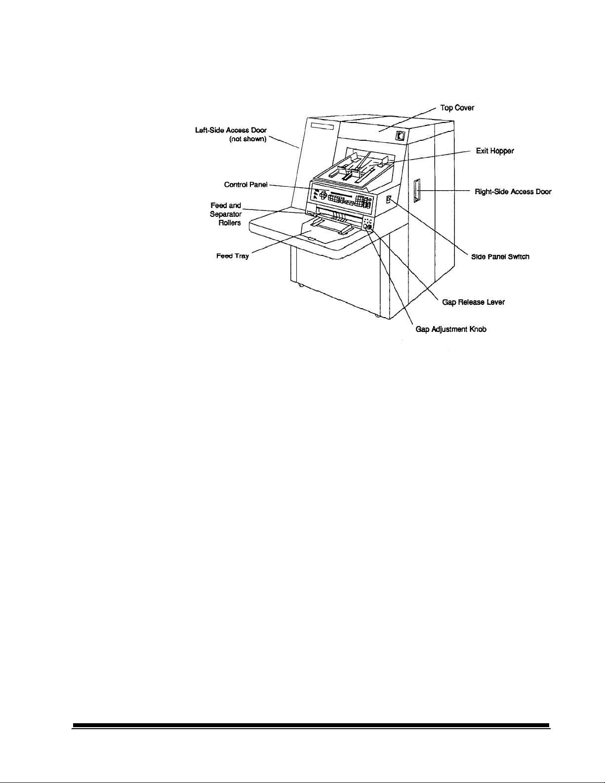
Scanner components
Front view
The following illustrations and descriptions will assist you in locating and
becoming familiar with the Scanner components:
Control Panel – contains the Status Display, Indicators, and Operating
Keys used to control the Scanner.
Exit Hopper – accepts documents after they have been scanned.
Feed and Separator Rollers – provide smooth feeding of documents of
various sizes and textures.
Feed Tray – holds documents prior to feeding.
Gap Adjustment Knob – allows you to manually adjust the space between
the feed and separator rollers for documents of varying thicknesses.
Gap Release Lever – allows you to open the feed gap for thicker
documents to be fed into the transport.
Left-Side Access Door – provides access to select components.
Right-Side Access Door – provides access to the transport system
components.
Side Panel Switch – allows you to turn the transport system on/off.
Top Cover – provides access behind the transport area.
A-41069 January 1993
1 - 3
Page 7

Rear view
Computer
Interface 1
(COIN1)
Computer
Interface 2
(COIN2)
Computer
Interface 3
(COIN3)
Power
Cord
Main
Power
Switch
SCSI
J30 J31 J45 J32 J33 J46
Computer Interface 1 (COIN1) - Service/Diagnostic Interface.
Used when configuring the Scanner and for running diagnostics.
Computer Interface 2 (COIN2) - OCR Command/Bar Code Interface.
Used for transferring commands between the Scanner and external
devices/subsystems.
Computer Interface 3 (COIN3) - SCSI Diagnostic Port Interface.
Used for system debugging and for monitoring SCSI-Host Computer
communications.
Main Power Switch – allows you to turn main power to the Scanner on/
off.
Power Cord – plugs into an appropriate power outlet.
ON
OFF
1 - 4
A-41069 January 1993
Page 8

Status display
Two Line
Status Display
Mode
Image Address
0030.05.100.001 MODE 5
Please Wait...
Operator Message
Scan Mode Simplex Duplex
Indicators: (one-sided; front) (two-sided; front and rear)
Document Level Level 1 Level 2 Level 3
Indicators:
Name/Number
Scan Mode
Indicator
Document Level
Indicator
A-41069 January 1993
1 - 5
Page 9
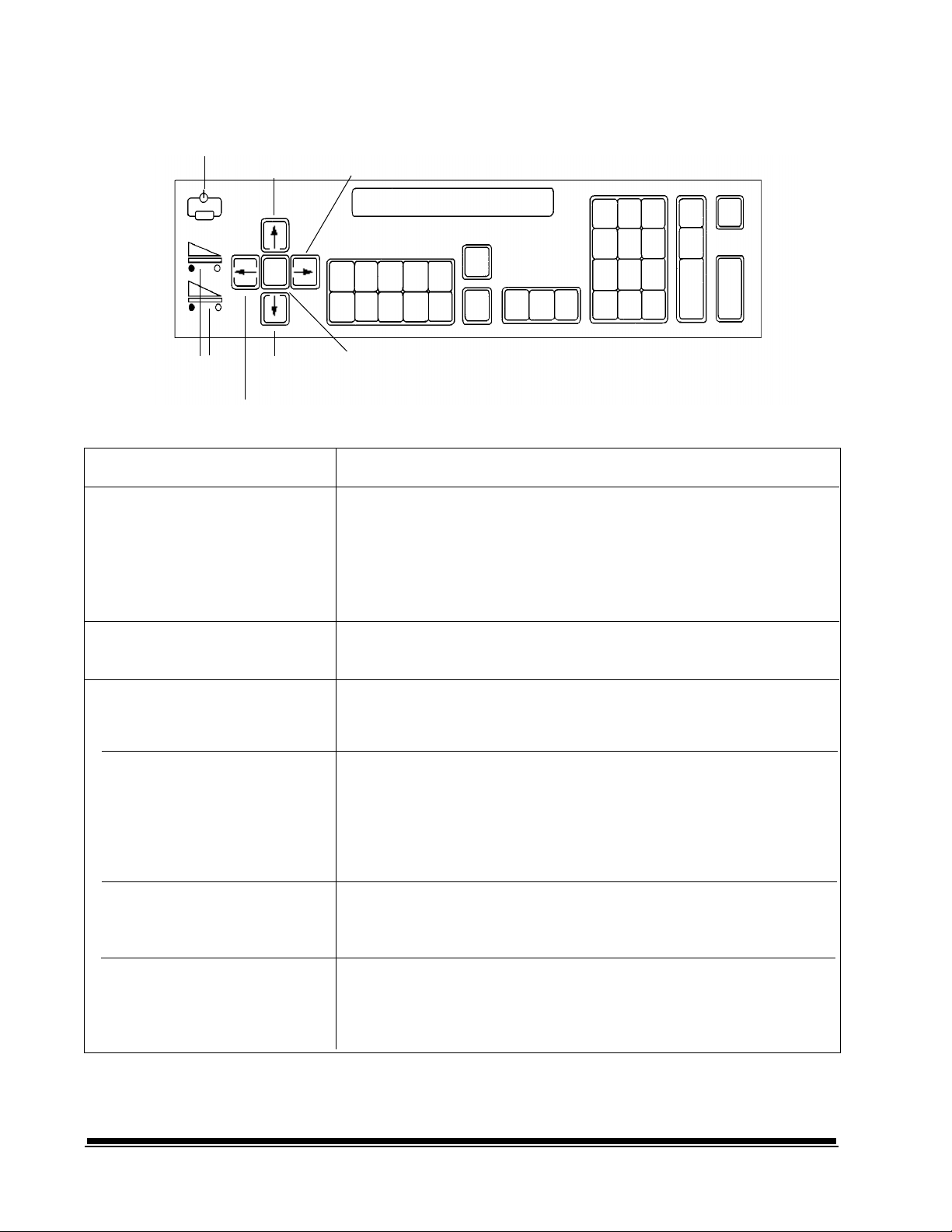
Operating keys and indicators
Indicator not in use
Up Arrow
+
Right Arrow
Scanner
Buffer
Indicators
Down Arrow
Left Arrow
Key/Indicator
Scanner Buffer Status Indicators
Plus key
Up Arrow
Right Arrow
Plus Key
Function
Indicates how much image buffer space is available:
A full image buffer is represented by only one light in the display;
An empty image buffer is represented by all lights in the display.
Upper indicator: represents the image buffer for front side images.
Lower indicator: represents the image buffer for rear side images.
Used when inputting a value for the Image Address. When pressed,
it allows a field to remain unchanged.
Used to increment values at a faster rate. Also used to increase a
data value when used with certain functions. Also used when
entering an alpha character in the Image Address Fixed Field.
Used to increment values at a slower rate. Also used to display
additional messages in the Status Display; a blinking cursor appears
over the arrow in the display as an indication that there are
additional messages. Press the right arrow key to display the
additional messages. Also used when entering an alphanumeric
character in the Image Address.
Down Arrow
Left Arrow
1 - 6
Used to decrement values at a faster rate. It is also used to
decrease a data value when used with certain functions. Also used
when entering an alpha character in the Image Address Fixed Field.
Used to decrement values at a slower rate. Also used to
backspace, delete the last keystroke, or clear messages in the
Status Display. Also used when entering an alphanumeric
character in the Image Address.
A-41069 January 1993
Page 10

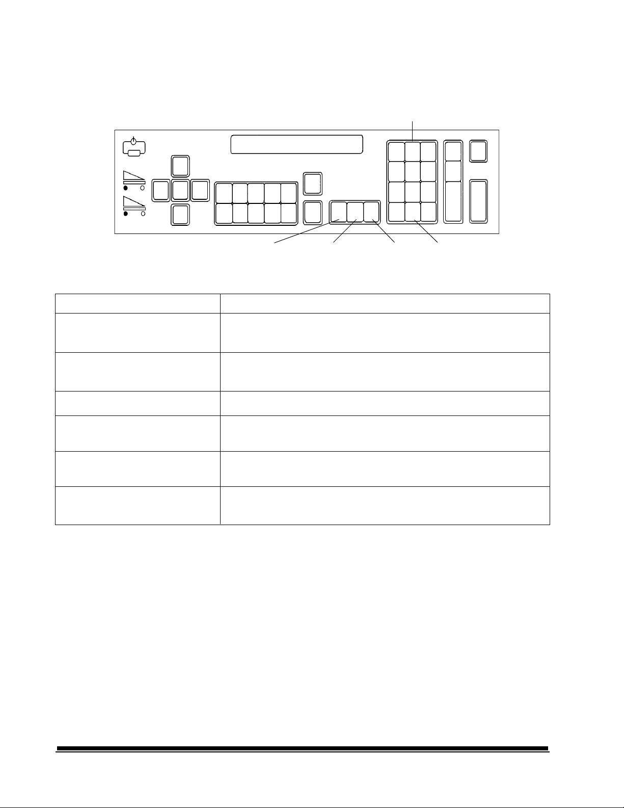
Operating keys and indicators
Keys/Indicators
CAL
END
Programmable Keys
(P Keys)
CAL
END
CAL
P6 P7 P8 P9 P10
Programmable Keys
P3 P4 P5
END
(P Keys)
Not used
Jog
Transport Jog
Function
Used to initiate the calibration process.
Used at the end of a batch or job to alert the host computer that the
batch or job has ended.
Used to perform specific functions. The P Keys have default values;
any or all of the defaults may be overridden/reprogrammed at
installation.
Jog Transport Jog
Used to momentarily turn on (jog) the transport system.
Used to help clear document jams.
A-41069 January 1993
1 - 7
Page 11
Operating keys and indicators
III III
Numeric Keys
7
8 9
4 5 6
1 2 3
.
0 F
Keys/Indicators
Numeric Keys (0 - 9)
F Key
Decimal Key
Level 1 Key
Level 2 Key
Level 3 Key
Level 2 KeyLevel 3 Key
Level 1 Key
Decimal Key
Function
Used to enter numeric data such as an Image Address or Function
Code.
Used to select one of the available functions, when used with the
numeric keys.
Used to insert a field separator in an Image Address.
Used to identify the next document fed into the Scanner as a Level
1 document.
Used to identify the next document fed into the Scanner as a Level
2 document.
Used to identify the next document fed into the Scanner as a Level
3 document.
1 - 8
A-41069 January 1993
Page 12
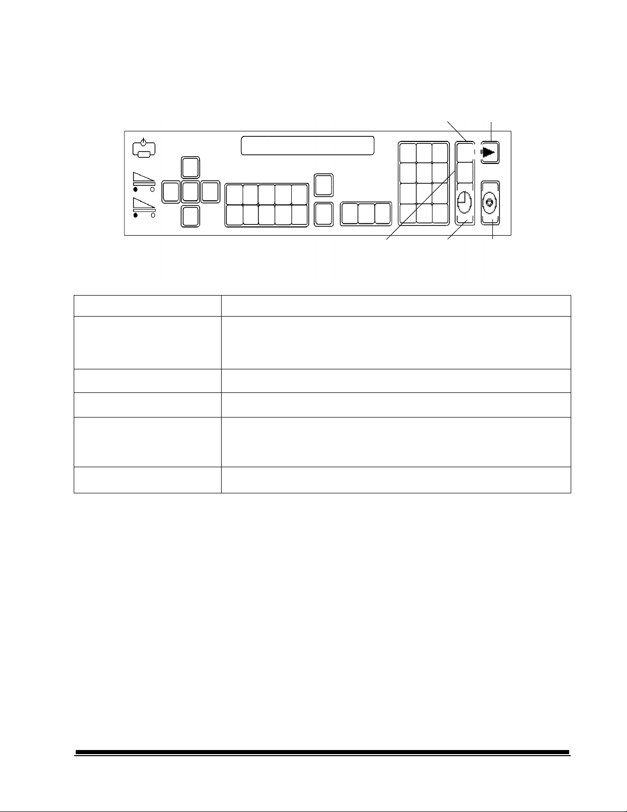
Operating keys and indicators
Key/Indicator
Clear
Cancel
Run
NEXT
Clear/Cancel
Run
C
Next
StopEnterNEXT
Function
Used to cancel a function without changing the preset values.
Used to clear the Status Display after executing select function codes.
Used to clear an operator message from the Status Display.
Used to turn on the feeder and transport system.
Allows operator to enter the next document Image Address.
Stop
Enter
Used to stop the feeder and transport system. Documents in the
transport system when the Stop key is pressed will be scanned and
placed in the exit hopper before the transport system stops.
Used to enter data for a Function Code or an Image Address change.
A-41069 January 1993
1 - 9
Page 13

2 BASIC CONCEPTS
The following information will provide you with the basic concepts
associated with scanning documents.
Modes
The Scanner offers eighteen (18) modes which may be defined for a
particular application or group of applications.
When you select a mode for use with a particular application, you are
selecting the format/appearance of the output. Each mode consists of
definitions which affect the output of the Scanner. Required mode
definitions include index format, level to follow level rules, etc. Optional
mode definitions include a variety of accessory options, such as turning
the endorser on or off. The mode definitions are established during
installation.
Many of the optional mode definitions established during installation
may be overridden using function codes. The overrides are temporary,
unless during installation it is specified that the mode overrides be
saved. Upon execution of a function which overrides a prior definition, a
plus sign (+) will appear in the first line of the status display if the mode
overrides are saved.
Mode override indicator
0030.05.100.001 MODE 5 +
Please Wait...
Linked modes
Linking modes eliminates the requirement of re-entering the Image
Address when changing from one mode to another. When two modes
are linked, you may change from one mode to another, maintaining the
Image Address.
Modes are linked by defining the same Index Format and Image
Address Fields (both number of fields and individual field lengths) during
installation.
NOTE: The Level Rule options defined during installation do not have to
be the same to link modes.
To change from one mode to another, maintaining the Image Address,
use Function Code F91.
2 - 1A-41069 January 1993
Page 14

The following example illustrates the use of linked modes.
• Assume that in Mode 10:
- The Index Format is three-level.
- The Image Address Level 3 field length is three (3) characters; the
Image Address Level 2 field length is two (2) characters; the Image
Address Level 1 field length is four (4) characters.
- The Level Rules are: Level 1 followed by Level 1; Level 2 followed by
Level 1; and Level 3 followed by Level 3.
• Assume that in Mode 12:
- The Index Format is three-level.
- The Image Address Level 3 field length is two (2) characters; the
Image Address Level 2 field length is two (2) characters; the Image
Address Level 1 field length is five (5) characters.
- The Level Rules are: Level 1 followed by Level 2; Level 2 followed by
Level 2; and Level 3 followed by Level 2.
• Assume that in Mode 14:
- The Index Format is three-level.
- The Image Address Level 3 field length is two (2) characters; the
Image Address Level 2 field length is two (2) characters; the Image
Address Level 1 field length is five (5) characters.
- The Level Rules are: Level 1 followed by Level 1; Level 2 followed by
Level 1; and Level 3 followed by Level 2.
Mode 10 and Mode 12 may not be linked; the Image Address field
lengths are not the same.
Mode 10 and Mode 14 may not be linked; the Image Address field
lengths are not the same.
Mode 12 and Mode 14 may be linked; the Index Format is three-level;
and the Image Address has three fields, each with the same length
NOTE: If you are currently in Mode 12 and want to change to Mode 14,
note the affect of different level rules on the Image Address:
assume that the Image Address of the last document fed into
the transport is 01.05.01234. The next Image Address
displayed while still in Mode 12 is 01.06.00000. However, if you
change to Mode 14, using Function Code F91, the next Image
Address displayed in Mode 14 is 01.05.01234.
2 - 2 A-41069 January 1993
Page 15

Image addresses
An Image Address is assigned to every document scanned. An Image
Address consists of four fields, each of which represent a different
document level. An Image Address has a maximum length of fifteen
(15) characters; twelve (12) alphanumerics (Field A, Field B, and Field C
must be numeric; the Fixed Field may contain alphanumerics) and three
(3) delimiters (inserted between fields).
The Image Address (number of fields and characters) is based upon the
indexing scheme chosen (refer to Indexing Schemes ).
Regardless of the indexing scheme used, the following four fields must
be defined during installation for each mode:
• Field A. A numeric field representing document Level 1.
Its value is incremented whenever a document is assigned Level 1.
• Field B. A numeric field representing document Level 2.
Its value is incremented whenever a document is assigned Level 2.
• Field C. A numeric field representing document Level 3.
Its value is incremented whenever a document is assigned Level 3.
• Fixed Field. An alphanumeric field containing fixed information;
typically, the date.
Assigning an image address
An example of an Image Address is:
1201.01.020.005
where:
• Field A (Level 1) contains 005.
• Field B (Level 2) contains 020.
• Field C (Level 3) contains 01.
• Fixed Field contains 1201.
An Image Address may be assigned or changed by pressing the NEXT key
or by entering Function Code F92. The NEXT key (or Function Code F97)
is used when setting/changing any or all of the Image Address fields.
Function Code F92 is used when setting/changing only the Fixed Field of
the Image Address.
2 - 3A-41069 January 1993
Page 16

Using the NEXT key
Using function code F92
To set or change an Image Address using the NEXT key (or Function Code
F97), simply press the NEXT key or enter Function Code F97.
The next Image Address will be displayed. An entry cursor will appear over
the first character of the next Image Address. Simply enter the desired
Image Address or use the left and right arrow keys to position the entry
cursor over the character to be set/changed and enter the desired value.
The Plus key (+) may also be used to move the entry cursor to the first
character in the next Image Address field, leaving the current Image
Address field unchanged.
All numeric keys (0 - 9) and the decimal key have dedicated keys on the
keyboard and can be entered directly.
For example if the current Image Address is 1201.01.020.005 and you want
to change it to 1201.02.000.000, the following steps would be used:
• Press the NEXT key or enter Function Code F97.
The entry cursor will appear over the first Fixed Field character
(1201.01.020.005).
• Press the Plus key (+) to leave the Image Address Field (1201)
unchanged.
• Enter .02.000.000.
• Press Enter to exit, saving the changes to the Image Address and
return to a normal operating display.
To set or change the Image Address Fixed Field, enter Function Code F92.
The number of characters in the Image Address Fixed Field is defined
during installation for each mode. Using Function Code F92, you will not be
allowed to enter more than the predefined number of characters.
The Fixed Field of the Image Address will be displayed. An entry cursor will
appear over the first character of the Fixed Field.
To enter numeric characters, simply input the desired value using the
numeric keys (0 - 9) on the keyboard and press Enter to input the value.
To enter alpha characters, you must enter the alpha entry mode by
pressing either the up or down arrow key. A portion of the alpha character
set will be displayed, with a flashing cursor appearing over one of the
characters.
If the desired alpha character does not appear in the display, press either
the up or down arrow key to display another portion of the alphabet.
The alpha character set consists of: upper-case English characters (A-Z), a
space ( ), six special characters ($ * - : < >), a dieresis (ä), beta (ß), n tilde
(ñ), o dieresis (ö), and u dieresis (ü).
NOTE: The plus sign (+) is also an acceptable character, input from the
control panel. However, it cannot be input as the first character
in the Fixed Field.
2 - 4 A-41069 January 1993
Page 17

Once the desired alpha character appears in the display, it may be selected
for input into the Fixed Field. To input the desired alpha character, use the
left or right arrow key to move the flashing cursor over the desired alpha
character. Press Enter to place the alpha character in the Fixed Field.
Repeat the process of entering alpha entry mode, and entering an alpha
character for each Fixed Field character.
For example, if the current Image Address Fixed Field is 1201 and you
want to change it to DEC5, the following steps would be used:
• Enter Function Code F92.
The entry cursor will appear over the first Fixed Field character
(1201).
• Press the up or down arrow key to enter alpha entry mode.
• Make sure that the letter D is displayed. If not, press the up or down
arrow key until the letter is displayed.
• Use the left or right arrow key to position the flashing cursor over the
letter D.
• Press Enter to place the letter D in the first Fixed Field character
position. Only the letter D will appear in the display, with the entry
cursor appearing in the next character position.
• Press the up or down arrow key to enter alpha entry mode.
• Make sure that the letter E is displayed. If not, press the up or down
arrow key until the letter is displayed.
• Use the left or right arrow key to position the flashing cursor over the
letter E.
• Press Enter to place the letter E in the second Fixed Field character
position. The letters DE will appear in the display, with the entry
cursor appearing in the next character position.
• Press the up or down arrow key to enter alpha entry mode.
• Make sure that the letter C is displayed. If not, press the up or down
arrow key until the letter is displayed.
• Use the left or right arrow key to position the flashing cursor over the
letter C.
• Press Enter to place the letter C in the third Fixed Field character
position. The letters DEC will appear in the display, with the entry
cursor appearing in the next character position.
• Press the numeric key 5 to place the number 5 in the fourth Fixed
Field character position.
• Press Enter to exit Function Code F92. saving the changes to the
Image Address and return to a normal operating display.
2 - 5A-41069 January 1993
Page 18

Image address formats The Image Address may be displayed in the status display, and printed
on the original document(s) as they are transported through the system.
The format in which the Image Address appears when displayed,
written, or printed is defined during installation for each mode.
The written/printed Image Address may appear in one of three formats:
• Display leading zeros format
004.003.002.001
• Suppress leading zeros format
004. 3. 2. 1
• Compress leading zeros format
004.3.2.1
NOTE: The format chosen does not affect the Fixed Field of the Image
Address; it is always displayed and printed in its entirety.
Indexing schemes
The purpose of scanning documents is to record the information
contained on the documents in an easily accessible form.
In order to access or retrieve the information recorded, an indexing
scheme is used to assist you in locating the desired information.
The indexing scheme is defined during installation for each mode.
The Scanner offers five indexing schemes:
• Single Level.
• Two Level.
• Two Level Offset.
• Three Level.
• Three Level Offset.
2 - 6 A-41069 January 1993
Page 19

Single level indexing
When using this scheme, the Image Address (IA) assigned to each
document is defined as follows:
• Field A (Level 1) is defined as having a field length greater than zero.
• Field B (Level 2) is defined as having a field length of zero.
• Field C (Level 3) is defined as having a field length of zero.
• Fixed Field may be defined, if desired.
Example of single level indexing
Let's use the scanning of a book as an example. Assume that the book
has fifty (50) pages.
The Image Address has been defined:
• Field A has a field length of three (3) characters.
• Field B has zero (0) characters.
• Field C has zero (0) characters.
• Fixed Field has zero (0) characters.
Page 1 Image Address 001
Page 2 Image Address 002
Page 3 Image Address 003
. . .
Page 50 Image Address 050
The first page is assigned Image Address 001. The second page is
assigned Image Address 002, and so on, through the remainder of the
book.
Any one of the fifty pages may later be located and retrieved using its
unique Image Address.
2 - 7A-41069 January 1993
Page 20

Two level indexing
Example of two level indexing
When using this scheme, the Image Address (IA) assigned to each
document is defined as follows:
• Field A (Level 1) is defined as having a field length greater than
zero.
• Field B (Level 2) is defined as having a field length greater than
zero.
• Field C (Level 3) is defined as having a field length of zero.
• Fixed Field may be defined, if desired.
Let's use the scanning of a book as an example. Assume that the
book contains two chapters; Chapter 1 has forty (40) pages and
Chapter 2 has sixty (60) pages.
The Image Address has been defined:
• Field A has three (3) characters.
• Field B has two (2) characters.
• Field C has zero (0) characters.
• Fixed Field has zero (0) characters.
2 - 8 A-41069 January 1993
Page 21

Chapter Image Address 01.000
One
Header
Page 1-1 Image Address 01.001
Page 1-2 Image Address 01.002
Page ...
Page 1-40 Image Address 01.040
Chapter Image Address 02.000
Two
Header
Page 2-1 Image Address 02.001
Page 2-2 Image Address 02.002
Page ...
Page 2-60 Image Address 02.060
The header page for Chapter 1 is assigned Image Address 01.000. The
first page of Chapter 1 is assigned Image Address 01.001. The second
page of Chapter 1 is assigned Image Address 01.002, and so on
through the remainder of Chapter 1.
The header page for Chapter 2 is assigned Image Address 02.000. The
first page of Chapter 2 is assigned Image Address 02.001. The second
page of Chapter 2 is assigned Image Address 02.002, and so on
through the remainder of Chapter 2.
Any one of the pages may later be located and retrieved using its
unique Image Address.
2 - 9A-41069 January 1993
Page 22

Two level offset indexing
When using this scheme, the Image Address (IA) assigned to each
document is defined as follows:
• Field A (Level 1) is defined as having a field length of zero.
• Field B (Level 2) is defined as having a field length greater than zero.
• Field C (Level 3) is defined as having a field length of zero.
• Fixed Field may be defined, if desired.
Example of two level offset
indexing
Let's use the scanning of a book as an example. Assume that the book
contains two chapters; Chapter 1 has forty (40) pages and Chapter 2
has sixty (60) pages.
The Image Address has been defined:
• Field A has zero (0) characters.
• Field B has two (2) characters.
• Field C has zero (0) characters.
• Fixed Field has zero (0) characters.
2 - 10 A-41069 January 1993
Page 23

Chapter Image Address 01
One
Header
Page 1-1 Image Address 01
Page 1-2 Image Address 01
Page ...
Page 1-40 Image Address 01
Chapter Image Address 02
Two
Header
Page 2-1 Image Address 02
Page 2-2 Image Address 02
Page ...
Page 2-60 Image Address 02
The header page for Chapter 1 is assigned Image Address 01. The
remaining pages of Chapter 1 are also assigned Image Address 01.
The header page for Chapter 2 is assigned Image Address 02. The
remaining pages of Chapter 2 are also assigned Image Address 02.
Either one of the chapter header pages may later be located and
retrieved using its unique Image Address. Pages within a chapter may
located and retrieved by first finding the chapter header and then
manually scrolling through the remaining pages of the chapter.
2 - 11A-41069 January 1993
Page 24

Three level indexing
When using this scheme, the Image Address (IA) assigned to each
document is defined as follows:
• Field A (Level 1) is defined as having a field length greater than zero.
• Field B (Level 2) is defined as having a field length greater than zero.
• Field C (Level 3) is defined as having a field length greater than zero.
• Fixed Field may be defined, if desired.
Example of three level indexing
Let's use the scanning of a book as an example. Assume that the book
contains two sections; Section One contains two chapters, each having
forty (40) pages; Section Two contains only one chapter, having
one-hundred twenty (120) pages.
The Image Address has been defined:
• Field A has three (3) characters.
• Field B has two (2) characters.
• Field C has one (1) character.
• Fixed Field has zero (0) characters.
2 - 12 A-41069 January 1993
Page 25
Section Image Address 1.00.000
One
Header
Chapter Image Address 1.01.000
One
Header
Section Image Address 2.00.000
Two
Header
Chapter Image Address 2.01.000
One
Header
Page 1-1 Image Address 1.01.001
Page ...
Page 1-40 Image Address 1.01.040
Chapter Image Address 1.02.000
Two
Header
Page 2-1 Image Address 1.02.001
Page ...
Page 2-40 Image Address 1.02.040
Page 1-1 Image Address 2.01.001
Page ...
Page 1-120 Image Address 2.01.120
The header page for Section 1 is assigned Image Address 1.00.000.
The header page for Chapter 1 of the section is assigned Image
Address 1.01.000. The pages within the Chapter are assigned Image
Address(es) 1.01.001 through 1.01.040. The header page for Chapter 2
of the section is assigned Image Address 1.02.000. The pages within
the Chapter are assigned Image Address(es) 1.02.001 through
1.02.040.
The header page for Section 2 is assigned Image Address 2.00.000.
The header page for Chapter 1 of the section is assigned Image
Address 2.01.000. The pages within the Chapter are assigned Image
Address(es) 2.01.001 through 2.01.120.
Any one of the pages may later be located and retrieved using its
unique Image Address.
2 - 13A-41069 January 1993
Page 26

Three level offset indexing When using this scheme, the Image Address (IA) assigned to each
document is defined as follows:
• Field A (Level 1) is defined as having a field length of zero.
• Field B (Level 2) is defined as having a field length greater than zero.
• Field C (Level 3) is defined as having a field length greater than zero.
• Fixed Field may be defined, if desired.
Example of three level offset
indexing
Let's use the scanning of a book as an example. Assume that the book
contains two distinct sections; Section One contains two chapters, each
having forty (40) pages; Section Two contains only one chapter, having
one-hundred twenty (120) pages.
The Image Address has been defined:
• Field A has zero (0) characters.
• Field B has two (2) characters.
• Field C has one (1) character.
• Fixed Field has zero (0) characters.
2 - 14 A-41069 January 1993
Page 27
Section Image Address 1.00
One
Header
Chapter Image Address 1.01
One
Header
Section Image Address 2.00
Two
Header
Chapter Image Address 2.01
One
Header
Page 1-1 Image Address 1.01
Page ...
Page 1-40 Image Address 1.01
Chapter Image Address 1.02
Two
Header
Page 2-1 Image Address 1.02
Page ...
Page 2-40 Image Address 1.02
Page 1-1 Image Address 2.01
Page ...
Page 1-120 Image Address 2.01
The header page for Section 1 is assigned Image Address 1.00. The
header page for Chapter 1 of the section is assigned Image Address
1.01. The remaining pages of Chapter 1 are also assigned Image
Address 1.01. The header page for Chapter 2 of the section is
assigned Image Address 1.02. The remaining pages of Chapter 2 are
also assigned Image Address 1.02.
The header page for Section 2 is assigned Image Address 2.00. The
header page for Chapter 1 of the section is assigned Image Address
2.01. The remaining pages of Chapter 1 are also assigned Image
Address 2.01.
Either one of the section header or chapter header pages may later be
located and retrieved using its unique Image Address. Pages within a
chapter may located and retrieved by first finding the chapter header
and then manually scrolling through the remaining pages of the chapter.
2 - 15A-41069 January 1993
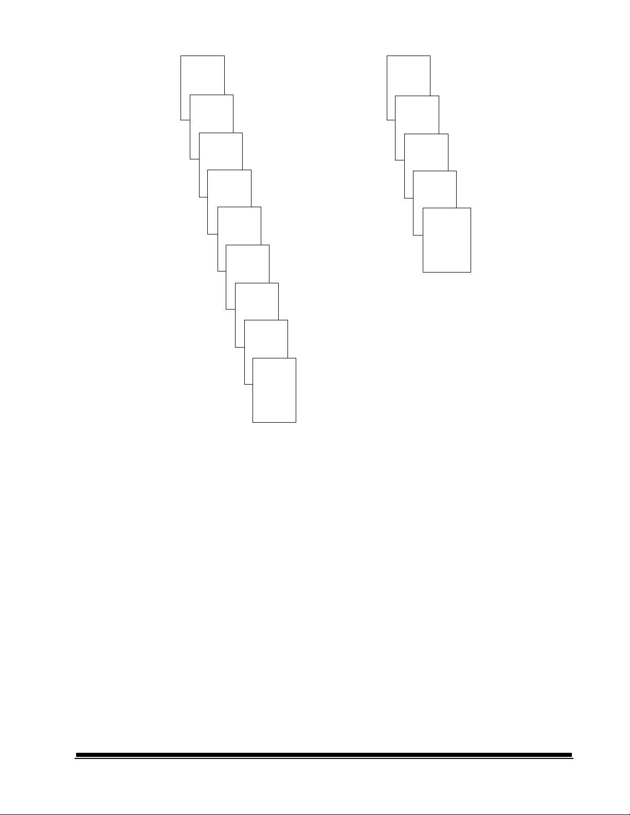
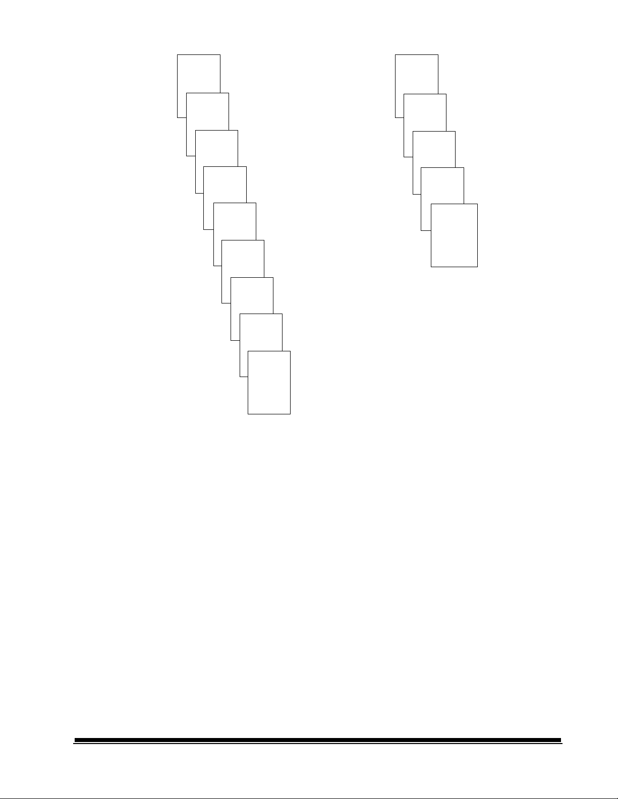
Page 28

Controlling document level changes
Throughout the Indexing Schemes examples, you have seen document
levels change within a single group of documents. There are four
document image levels: 3, 2, 1, and 0.
There are a number of ways in which user can set or change the
document level:
• You may press a document Level Key on the Control Panel to assign
a document Level 3, 2, or 1.
• You may use Function Code F07 to assign a document Level 0.
• You may use the optional KODAK IMAGELINK™ Footswitch
accessory; pressing, pressing and holding, or releasing the Footswitch
can change document levels.
• You may use the optional KODAK IMAGELINK™ Patch Reader
accessory; feeding a document containing a particular type of patch
can change document levels.
If the user does not set or change the document level using one of the
methods listed, the document level will be set automatically based upon
the Level Rules (i.e., Level 2 is followed by Level 1, etc.) defined during
installation for each mode.
The following diagram illustrates how document levels are set or
changed:
Image
Mark
Level
III
Image
Mark
Level
II
Level
I
Level
I
Level
II
Level
I
Level
I
Generated Automatically
Level Instruction:
Operator presses III key or uses a patch III
document (Levels II and I documents are
then generated automatically depending
on Index Mode).
Level
II
Level Instruction:
Operator presses II key or uses a patch II
document (Level I documents are then
generated automatically depending on
Index Mode).
LevelILevel
I
Generated Automatically
Generated Automatically
Level Instruction:
Operator presses II key (Level I documents are
then generated automatically depending on
Index Mode).
Level
III
Level Instruction:
Operator pressess III (Levels II and I documents
are then gererated automatically depending on
Index Mode).
Level
II
Generated Automatically
Level
I
2 - 16 A-41069 January 1993
Page 29

Batching
A batch is defined as a specific number of documents of a given level
(Level 1, Level 2, or Level 3). Prior to processing, a predefined action
may take place. During processing, when the specified number of
documents of the given level have been processed, a predefined action
will take place.
The start-of-batch and end-of-batch actions are defined during
installation for each mode.
When batching is enabled in the current mode, a B will appear in the
first line of the status display.
Batching indicator
0030.05.100.001 MODE 5 B
Please Wait...
Special considerations
Checking the meters
The topics presented in this section apply to the general usage of the
Scanner.
Checking the meters is useful in determining:
• maintenance schedules.
• the length of time required to complete a job.
To view the run time display, enter Function Code F17. The display will
show three (3) meters: Meter A shows the number of motor-on hours;
Meter B shows the number of transport-on hours; and Meter C shows
the number of AC-on hours. Press the right arrow key to view each
meter in turn. In addition, the non-resettable document count is shown
as Meter D.
0030.05.100.001 MODE 5
Meter A: 10 ->
Press the Clear key to clear the display.
2 - 17A-41069 January 1993
Page 30

Scanning considerations
The topics presented in this section apply to document scanning.
Image headers
Image Headers are created when documents are scanned. Each
scanned document has its own individual image header, containing
information such as:
• Document number (sequential number)
• Image size
• Document Level
• Mode
• Line length
• Page length
• Image Address
• Compression type
• Date
• Time
• Resolution
• Bit Order
• Skew
• Header flags
• Optional information (i.e., bar code information)
The document image header is sent ahead of the scanned document
image to the host computer. The image header and document image
are then stored on a magnetic or optical disk media. The information
contained in the header is later used to retrieve the document images
(most often using the Image Address or bar code information stored in
the header).
Header flags
2 - 18 A-41069 January 1993
Header flags are used to alert the host system that the document(s) fed
into the transport are of special interest. There are two types of flags:
latched and momentary.
The latched flag is activated by performing Function Code F73.
When the latched flag is set, the Image Header for the current document
(or the next document fed into the transport) and all documents which
follow will contain a header flag. The latched flag will remain activated
until it is turned off by again performing Function Code F73.
NOTE: A flag symbol will appear in the first line of the status display
until the latched flag is turned off.
The momentary flag is activated by performing Function Code F74.
When the momentary flag is set, the Image Header for the current
document (or the next document fed into the transport) only will contain
a header flag.
Page 31

3 GETTING STARTED
The following steps are necessary to prepare the Scanner for operation:
• Turn on the Main Power Switch (located at the rear of the machine).
• Turn on the Side Panel Switch.
• Select the language display.
• Calibrate the Scanner.
• Adjust the Feed and Separator Roller gap.
• Adjust the Feed Shelf position.
• Adjust the Feed Shelf Side Guides.
• Adjust the Exit Hopper Side Guides and End Stop.
• Change the Deflector (if required).
• Prepare documents for scanning.
Turning on the Scanner
Selecting the language display
The following steps are required to power on the Scanner:
1. Turn on the Main Power Switch (located at the rear of the
machine).
NOTE: It is not necessary to turn off the Main Power Switch during
normal daily operation.
2. Turn on the Side Panel Switch.
Wait until the Status Display indicators are lit and an operating
display appears before you continue.
0030.05.100.001 MODE 1
The Scanner may have been configured at installation to allow use of a
second language in the status display. The language used (French,
German, Italian, Spanish, or other) is defined during installation. If
available, the alternate language display may be accessed using Function
Code F19.
A-41069 January 1993
3 - 1
Page 32

Calibrating the Scanner
Calibration sets the intensity of the lamps, which contribute to the overall
quality of the scanned document image.
The Scanner should be calibrated:
• At least once a day when the Scanner is turned on using the Side
Panel Switch - prior to scanning documents.
• Any time the Scanner is turned on using the Main Power Switch.
• If image quality is poor.
• After changing lamps.
Calibrate the Scanner using a calibration target (sheet of paper) that is:
• Blank.
• Clean.
• Matte finish (not glossy).
• White or the same color as the background color of the documents to
be scanned. If you are scanning a variety of colored documents, use
a white calibration target.
• Wider than the documents you are going to scan (i.e. to scan 8.5 x 11
inch (215.9 x 279.4 mm) documents, the calibration target should be
wider than 8.5 inches/215.9 mm). The recommended width for the
calibration target is 12 inches (300 mm).
1. Verify that the Main Power Switch (located at the rear of the
Scanner) and Side Panel Switch are on. A normal operating Status
Display should appear.
2. Press P-Key P1 or enter Function Code F37 to initiate the
calibration sequence.
3. Insert the calibration target into the feeder.
Calibration
Target
When the calibration is successful, the Status Display will return to a
normal operating display.
3 - 2 A-41069 January 1993
Page 33

Unsuccessful calibration If the calibration is not successful, a message will appear in the Status
Display.
You may need to:
• Verify that you are using a clean, blank sheet of paper as a calibration
target.
• Verify that there is not a document already in the document path.
Refer to Troubleshooting - Clearing the document path.
• Clean the Imaging Guides. Refer to Maintenance - Cleaning the
imaging guides.
• Calibrate the Scanner again. If this calibration attempt fails, change
the lamps. Refer to Maintenance - Replacing the exposure lamps.
If the required action has been taken and another calibration attempt
fails, contact your local service representative.
A-41069 January 1993
3 - 3
Page 34

Adjusting the feed and separator roller gap
The gap adjustment knob on the Control Panel increases or decreases
the space between the feed and separator rollers. The gap must be
adjusted properly for smooth transportation of documents without
document overlap.
When documents of different thicknesses are fed in a group, adjust the
gap using the thinnest document in the group.
The feed and separator roller gap may have to be adjusted to
compensate for:
• Very thin documents (onion skin, tracing paper, etc.).
• Very thick documents (card stock, punch cards, cover stock).
• Some coated documents (photographic paper, plastic-coated paper).
If the gap is not adjusted properly:
• More than one document at a time may be drawn into the transport
system at the same time; not all of the documents will be scanned.
• Documents may be drawn into the transport too quickly; documents
may overlap or be spaced to closely (causing an error display).
• Documents may become skewed during transport; jamming may
occur.
NOTE: Prior to performing the adjustment procedure outlined in this
section, the Scanner must be calibrated and enabled.
1. Turn on the Side Panel Switch.
2. Enter Function Code F04 and enable counting-only.
3. Press Enter.
4. Press Run.
IMPORTANT: Do not make a gap adjustment while documents are in
the feeder or transport system; doing so will produce an
inaccurate adjustment.
3 - 4 A-41069 January 1993
Page 35

5. Turn the Gap Adjustment Knob clockwise three complete turns to
open the gap between the feed and separator rollers.
6. Select two documents of the same size, texture and thickness,
similar to the types of documents you will be processing.
7. Place one document on top of the other. Hold them firmly by their
trailing edges. Insert them into the gap approximately 0.125 (1/8)
inch (3 mm).
If the documents separate, repeat the following steps until the
documents do not separate:
a. Turn the Gap Adjustment Knob clockwise one-half (1/2) turn.
b. Insert the documents again.
If the documents do not separate, proceed with Step 8.
8. Rotate the Gap Adjustment Knob counterclockwise one or two
clicks.
9. Hold the trailing edges of the documents firmly. Insert them into the
gap.
If the bottom document is not separating from the top document,
remove the documents and repeat Steps 8 and 9 until the bottom
document separates from the top document.
A-41069 January 1993
If the bottom document is separating from the top document,
proceed with Step 10.
3 - 5
Page 36

10. When you have adjusted the gap so that the bottom document
separates consistently from the top document, rotate the Gap
Adjustment Knob counterclockwise another one or two clicks to
complete the adjustment.
11. Feed a stack of fifty (50) to one-hundred (100) documents twice
through the transport system. Verify that the final count reflects the
total number of documents that were fed and that the counter shows
the same amount each time the documents are counted.
If the count is not the same, the gap is not adjusted correctly. Rotate
the Gap Adjustment Knob counterclockwise another one or two
clicks and repeat Step 10. Repeat until corrected.
12. Press Stop.
13. Enter Function Code F04 and disable counting-only.
14. Press Enter.
3 - 6 A-41069 January 1993
Page 37

Adjusting the feed shelf position
Before you begin feeding documents into the Scanner, adjust the
position of the Feed Shelf:
Feed Shelf
Work Shelf
Notch
Groove
Height
Adjustment
Legs
To automatically feed multiple documents, the feed shelf should be in
the raised position (as shown above). To raise the feed shelf, grasp the
notch and lift the feed shelf. Swing the height adjustment legs out and
insert them into the groove on the work shelf.
To hand feed documents (one at a time), the feed shelf should be in the
down position (not shown). To lower the feed shelf, grasp the notch and
lift the feed shelf until the height adjustment legs are no longer resting in
the groove on the work shelf. Tuck the height adjustment legs in and
gently lower the feed shelf into position, level with the work shelf.
A-41069 January 1993
3 - 7
Page 38

Adjusting the feed shelf side guides
Before you begin processing documents, adjust the side guides on the
feed shelf to accomodate the documents being processed.
2. Slide apart the Side Guides on the Feed Shelf until the Feed Shelf
Label is visible.
Center line
2. Center the documents across the feed shelf label. Adjust the feeder
side guides dependent upon the width of the document. Leave
approximately 0.0625 (1/16) inch (2 mm) clearance on each side of
the documents so that they will feed properly.
NOTE: If the documents are larger than the area shown on the
Feed Shelf Label and do not fit between the Side Guides,
rotate and reposition the documents within the Side Guides.
3 - 8 A-41069 January 1993
Page 39

Adjusting the exit hopper side guides and end stop
The Exit Hopper Side Guides and End Stop must be adjusted so that
documents will be stacked properly after processing.
1. Adjust the Side Guides on the Exit Hopper to match the adjustment
of the Side Guides on the Feed Shelf.
2. Adjust the End Stop of the Exit Hopper by determining the longest
document to be processed. Slide the End Stop until the Arrows
point to where the length of the longest document is shown on the
Exit Hopper Label.
A-41069 January 1993
3 - 9
Page 40

Changing the deflector
The Scanner comes with two deflectors (stored in the pocket located
inside the right-side access door), designed to help stack the documents
as they exit the transport system and enter the exit hopper.
Use the short deflector for documents less than 5 inches (13 cm) and
the long deflector for documents longer than 5 inches (13 cm) as well as
for mixed sizes.
1. Grasp the deflector near the attachment pin (as shown).
2. Guide the deflector into the exit hopper, just below the lip of the
hopper, to insert the attachment pin in the holding clip.
3. Pull the deflector toward you until it clicks into place.
3 - 10 A-41069 January 1993
Page 41

Preparing documents for scanning
Before you begin processing documents, make certain that the
documents may be fed through the Scanner easily:
• Remove any staples, rubber bands, loose mending tape, or paper
clips from the documents to be processed.
• Straighten wrinkled edges and tape any torn documents.
• Trim ragged edges.
When using the automatic feeder, make certain all documents are of
similar size and, texture, thickness, and weight, and that the leading
edges of all documents are aligned.
A-41069 January 1993
3 - 11
Page 42

4 OPERATING THE SCANNER
Overview
The scanning process consists of the following steps:
1. The Scanner is prepared for operation (refer to
2. The Scanner is enabled by the host system.
3. A mode is selected for the application. Typically this step is
performed by the host computer, but it may also be performed by
the operator.
4. Temporary operating values are selected (if required).
5. The Run key is pressed.
6. Documents are fed into the transport.
• The Scanner assigns a Sequential ID Number (for digital image
storage), the document Image Level and Image Address.
• The document is scanned.
• The document Image Header is created.
• The host computer initiates transfer of the document Image
Header and document image to the host system for storage on
magnetic or optical disk media.
Getting Started ).
Documents are deposited in the exit hopper, face down, in the
order in which they were fed into the transport.
7. The Stop key is pressed.
8. A Scanner End-of-Job is executed.
9. The side panel switch is turned off until ready for the next
application.
The main power switch is turned off (optional - performed only when
the Scanner will be out of operation for more than eight (8) hours;
not necessary during normal daily operation).
A-41069 August 1995
4 - 1
Page 43

Selecting a mode
The Scanner offers eighteen (18) modes which may be programmed for
a particular application or group of applications.
The modes are programmed at the time of installation and stored for
easy access and use.
Typically, the mode will be selected via the host system, using a
scanner-unique command. However, the operator may manually select
a mode.
There are two methods which may be used by the operator to select a
mode:
• Use Function Code F01, Select Mode, to enter a mode number.
- Press the F key.
- Press the numeric key 0 and then 1.
- Press Enter.
- Press the numeric keys which correspond to the desired mode.
(i.e., to enter mode number 15, press the numeric key 1 and then 5.)
- Press Enter.
• The mode selection function may be preprogrammed and accessible
using one of the P-keys. Ask your system administrator if any one
of the P-keys has been programmed to perform this function.
Temporary operating values
Each of the eighteen (18) modes which are programmed at the time of
installation contain definitions which affect the output of the Scanner.
Each mode is programmed to conform to the output requirements of a
particular application or group of applications.
There may be instances, however, when a particular application
requires some variation of an existing mode. In such instances, mode
definitions may be changed using available Function Codes.
NOTE: Changes to mode definitions will remain in effect until another
mode is selected or the side panel switch is turned off. The
original mode definition is only affected by these changes if the
mode overrides are saved (the mode override option may be
selected at installation and if selected, a plus sign (+) will
appear in the first line of the status display).
Example:
Assume that mode 15 contains definitions which allow use of the
KODAK IMAGELINK™ Endorser. The starting print position (which
defines how far from the leading edge of the document the endorsement
is printed) is programmed to be 0.5 inches.
4 - 2
If there is a special application which requires that the endorsement be
printed 1.0 inch from the leading edge of the document, you may use
Function Code F59 to temporarily change the starting print position.
A-41069 August 1995
Page 44

Feeding documents
After the Scanner has been prepared for operation and the desired
mode and any temporary operating values have been defined, you are
ready to feed documents into the transport.
1. Verify that the side panel switch is on. Also verify that all of the
proper adjustments have been made (feeder side guides, exit
hopper side guides, etc.).
2. Press the Run key.
3. Select a stack of documents which is no more than 1.5 inch thick.
4. Fan the stack of documents so that the leading edge of the top
document will engage the feed/separator rollers first (refer to the
illustration above).
5. Place the stack of fanned documents into the feeder so that the
leading edge of the top document contacts the feed/separator
rollers. The documents will be drawn into the transport, with the top
document being fed first. The documents will be deposited in the
exit hopper face down, in the order in which they were fed into the
transport.
6. Repeat steps (3) through (5) until all of the application documents
have been fed into the transport.
7. Press the Stop key after all documents have been deposited in the
exit hopper.
A-41069 August 1995
4 - 3
Page 45

Feeding thick documents
The Gap Release Lever is used to feed thick documents such as card
stock or cover stock. The lever is located on the front panel of the
Scanner, next to the gap adjustment knob.
1. Press down and hold the gap release lever. This opens the gap
between the feed and separator rollers, allowing thick documents to
pass between them. You will be able to see the gap open as the
lever is pushed down.
2. Insert the thick document past the rollers until it is taken into the
transport system.
NOTE: If more than one thick document is to be scanned,
feed them into the transport one at a time.
4 - 4
3. After the thick document(s) have been scanned, release the gap
release lever. It will return to its original position. The feed and
separator rollers will return to their previously adjusted positions.
A-41069 August 1995
Page 46

5 FUNCTION CODES
Using function codes
There are a variety of functions available which may be used to
temporarily change operating conditions and values, and to obtain
system and accessory status information.
To execute a function code:
• Press the F key.
• Press the numeric keys which correspond to the desired function code.
• Press the Enter key.
Additional input may be necessary:
If the function is used to enable/disable an option
(turn an option on or off):
• Press the number one (1) key to turn the option ON;
or
Press the number zero (0) key to turn the option OFF.
• Press the Enter key.
If the function requires numeric input:
• Press the number key(s) required.
• Press the Enter key.
If the function is used to increment/decrement a measurement:
• Press the up arrow key to increment the measurement by
1 inch (25 mm);
or
Press the down arrow key to decrement the measurement by
1 inch (25 mm);
or
Press the right arrow key to increment the measurement by
1/8 inch (3 mm);
or
Press the left arrow key to decrement the measurement by
1/8 inch (3 mm).
• Press the Enter key.
To cancel a function or clear the Status Display after executing a
function, press the Clear/Cancel key.
A-41069 January 1993
5-1
Page 47

Function code summary
Status
Accessory Status* F05
Date and Time Display* F23
Elapsed Time* F17
Counters
Level 0 Count* F10
Level 1 Count* F11
Level 2 Count* F12
Level 3 Count* F13
Total Document Count* F09
Reset Level Counts F14
Setup
Action/Confirmation Tone F93
Alarm Tone F16
Alarm Volume F15
Change Date F22
Change Time F21
Display Contrast F18
Display Language F19
Measurement System F20
Operator ID F34
Scanner Calibration F37
Mode
Select Mode F01
Select Linked Mode F91
Counting Only F04
Restore Mode F02
Index/Image Address
Last Image Address* F08
Level 0* F07
Level 1* F94
Level 2* F95
Level 3* F96
Fixed Field F92
Next Image Address F97
Scanning
Scanner Calibration F37
Latched Scanning Flag* F73
Momentary Scanning Flag* F74
Scanner End-of-Job F38
Operation
Run F99
Terminate Batch* F06
Stop* F98
5-2
A-41069 January 1993
Page 48

Bar Code
Bar Code Reading On/Off F60
Partial Bar Code Reading On/Off F66
Bar Code Reading Confirmation Tone F63
Bar Code/Patch Reading Conf. Tone F62
Bar Code Test F65
Omit Bar Code Reading on Next Doc.* F64
Document Controller
Length Checking On/Off F70
Omit Length Checking on Next Doc.* F71
Skew Detection F72
Document Printers
All Document Printers On/Off F40
Primary Document Printer 1 On/Off F41
Secondary Document Printer 1 On/Off F42
Document Printer 12 On/Off F43
Omit Printing on Next Document* F44
Print Position F46
Print Test F45
Printer Character Shift F39
Printer Open Jet Test F56
Purge Frequency F49
Purge Print Head* F48
Endorser
Endorser On/Off F57
Endorser Mode F58
Endorser Print Position F59
Footswitch
Footswitch Confirmation Tone F75
OCR
OCR On/Off F76
Patch Reader
Patch Reader 1 On/Off F50
Patch Reader 2 On/Off F51
End Fed Patch Reading On/Off F52
Patch Reading Confirmation Tone F53
Omit Patch Reading on Next Doc.* F54
A-41069 January 1993
* May execute while
transport is running.
5-3
Page 49

Function code descriptions
F01 Select Mode
Allows you to select one of the eighteen (18) application modes.
FFF.003.002.001 Mode 10
Mode:
• Enter the number of the application mode you wish to select; one or two
digits.
• Press the Enter key.
F02 Restore Mode
Allows you to restore the current application mode to its default status
(as it was defined at installation), provided that mode overrides are
not saved.
FFF.003.002.001 Mode 10
A normal operating display will appear.
F04 Counting Only
Allows you to count documents only, with no filming, scanning, etc.
FFF.003.002.001 Mode 10
Count Only Mode OFF 1=ON
• Enter the number one (1) to turn Counting Only ON.
• Press the Enter key.
FFF.003.002.001 Mode 10
Count Only Mode ON 0=OFF
• Enter the number zero (0) to turn Counting Only OFF.
• Press the Enter key.
5-4
A-41069 January 1993
Page 50

F05 Accessory Status
Allows you to display the current status of each accessory installed.
The status of each accessory is either ON, OFF, or NOT PRESENT
(except for Endorser Mode, where the status is either Single Stamping,
Continuous Stamping, or NOT PRESENT).
Accessory Status ( ):
Endorser ON
->
->
• Press the down arrow key to view the next accessory; or
Press the up arrow key to view the previous accessory.
• Press the Cancel key at any time to return to a normal operating display.
The accessories appear in the order listed:
Endorser
Endorser Mode
Document Printer #1
Document Printer #2
Document Printer 12
Patch Reader #1
Patch Reader #2
End Fed Patches
Patch Read Confirmation Tone
Front Bar Code Reading
Front Partial Bar Code
Bar Code Confirmation Tone
Bar Code / Patch Conf Tone
Skew Detection
Length Checking
Foot Switch Confirmation Tone
OCR
A-41069 January 1993
F06 Terminate Batch
Allows you to prematurely end a batch.
NOTE: The predefined end-of-batch function(s) will be executed.
FFF.003.002.001 Mode 10
End of Batch
FFF.003.002.001 Mode 10
Last Image Address: FFF.003.001.098
• Press the Clear key to return to a normal operating display.
5-5
Page 51

F07 Level 0
Allows you to assign Level 0 to the next document fed into the transport.
FFF.003.002.001 Mode 10
A normal operating display will appear.
F08 Last Image Address
Allows you to display the Image Address of the last document processed.
FFF.003.002.001 Mode 10
Last Image Address: FFF.003.001.098
• Press the Clear key to return to a normal operating display.
F09 Total Document Count
Allows you to display the total number of documents processed.
FFF.003.002.001 Mode 10
Total Document Count: 123456789
• Press the Clear key to return to a normal operating display.
F10 Level 0 Count
Allows you to display the total number of documents assigned Level 0.
FFF.003.002.001 Mode 10
Level 0 Count: 123456789
• Press the Clear key to return to a normal operating display.
F11 Level 1 Count
Allows you to display the total number of documents assigned Level 1.
FFF.003.002.001 Mode 10
Level 1 Count: 123456789
5-6
• Press the Clear key to return to a normal operating display.
A-41069 January 1993
Page 52

F12 Level 2 Count
Allows you to display the total number of documents assigned Level 2.
FFF.003.002.001 Mode 10
Level 2 Count: 123456789
• Press the Clear key to return to a normal operating display.
F13 Level 3 Count
Allows you to display the total number of documents assigned Level 3.
FFF.003.002.001 Mode 10
Level 3 Count: 123456789
• Press the Clear key to return to a normal operating display.
F14 Reset Level Counts
Allows you to reset all counters to zero (Level 0 Counter, Level 1 Counter,
Level 2 Counter, and Level 3 Counter).
FFF.003.002.001 Mode 10
Level Count Reset
• Press the Enter key.
F15 Alarm Volume
Allows you to adjust the volume of the alarm.
FFF.003.002.001 Mode 10
Changing Volume of Tone ( )
->
->
• Press the up arrow key to increase the volume; or
Press the down arrow key to decrease the volume.
• Press the Enter key.
A-41069 January 1993
5-7
Page 53

F16 Alarm Tone
Allows you to adjust the pitch of the alarm tone.
There are two available options: LOW or HIGH.
FFF.003.002.001 Mode 10
Alarm Tone ( ): LOW
->
->
• Press the up arrow key to increase the pitch; or
Press the down arrow key to decrease the pitch.
• Press the Enter key.
F17 Elapsed Time
Allows you to display the number of hours the motor, transport, and AC
have been running. In addition, the non-resettable document count is
displayed.
FFF.003.002.001 Mode 10
Meter A: 10 ->
• Press the right arrow key to view all four time meters:
Meter A shows the number of motor-on hours;
Meter B shows the number of transport-on hours;
Meter C shows the number of AC-on hours; and
Meter D shows the non-resettable document count.
• Press the Cancel key to return to a normal operating display.
F18 Display Contrast
Allows you to adjust the contrast of the Status Display.
FFF.003.002.001 Mode 10
->
Changing Contrast of Display ( )
->
• Press the up arrow key to increase the contrast; or
Press the down arrow key to decrease the contrast.
• Press the Enter key.
5-8
A-41069 January 1993
Page 54

F19 Display Language
Allows you to choose the language in which Status Display messages
appear.
There are two available options: ENGLISH or OTHER (where OTHER is
defined as a specific language during installation).
FFF.003.002.001 Mode 10
Display Language: ENGLISH
• Press any arrow key (up arrow, down arrow, right arrow, or left arrow) to
toggle between the two available options.
• Press the Enter key.
F20 Measurement System
Allows you to choose the measurement system in which lengths are
displayed.
There are two available options: ENGLISH or METRIC.
FFF.003.002.001 Mode 10
Measurement Units Displayed: ENGLISH
• Press any arrow key (up arrow, down arrow, right arrow, or left arrow) to
toggle between the two available options.
• Press the Enter key.
F21 Change Time
Allows you to change the time.
Current Time is: 0929
Enter New Time (HHMM):
• Enter the new time in the format illustrated.
• Press the Enter key.
F22 Change Date
Allows you to change the date.
Current Date is: 09091992
A-41069 January 1993
Enter New Date (MMDDYYYY):
• Enter the new date in the format illustrated.
• Press the Enter key.
5-9
Page 55

F23 Time and Date Display
Allows you to view the current time and date.
NOTE: You cannot change the time or date using this function.
Formatted Time and Date:
9/9/92 9:30AM
• Press the Clear key to return to a normal operating display.
F34 Operator ID
Allows you to display the operator ID number.
Also allows you to change the operator ID number.
FFF.003.002.001 Mode 10
Operator ID: 0 01
• Enter a new operator ID, up to three (3) digits.
• Press the Enter key.
F37 Scanner Calibration
Allows you to initiate the calibration process required before scanning
documents.
FFF.003.002.001 Mode 10
Feed Calibration Target...
• Feed calibration target.
F38 Scanner End-of-Job
Allows you to signal the host computer that the last document of the job
has been fed into the transport.
FFF.003.002.001 Mode 10
A normal operating display will appear.
5-10
A-41069 January 1993
Page 56

F39 Printer Character Shift
NOTE: This function code is available only when using Document
Printer 12.
Allows you to select which set of ink jets will be used to print each
character.
There are three available options: Left, Center (default), or Right.
Printer Character Shift: 2
1=Left 2=Center 3=Right
• Enter the number 1 to select the left set of ink jets; or
Enter the number 2 to select the center set of ink jets; or
Enter the number 3 to select the right set of ink jets.
• Press the Enter key.
F40 All Document Printers On/Off
Allows you to turn all document printers (Document Printer 1 (primary),
Document Printer 1 (secondary), and Document Printer 12) on or off.
FFF.003.002.001 Mode 10
All Document Printers ON 0=OFF
• Enter the number zero (0) to turn all document printers OFF.
• Press the Enter key.
FFF.003.002.001 Mode 10
All Document Printers OFF 1=ON
• Enter the number one (1) to turn all document printers ON.
• Press the Enter key.
A-41069 January 1993
5-11
Page 57

F41 Primary Document Printer 1 On/Off
Allows you to turn the primary document printer 1 on or off.
FFF.003.002.001 Mode 10
Document Printer #1 ON 0=OFF
• Enter the number zero (0) to turn the primary document printer 1 OFF.
• Press the Enter key.
FFF.003.002.001 Mode 10
Document Printer #1 OFF 1=ON
• Enter the number one (1) to turn the primary document printer 1 ON.
• Press the Enter key.
F42 Secondary Document Printer 1 On/Off
Allows you to turn the secondary document printer 1 on or off.
FFF.003.002.001 Mode 10
Document Printer #2 ON 0=OFF
• Enter the number zero (0) to turn the secondary document printer 1 OFF.
• Press the Enter key.
FFF.003.002.001 Mode 10
Document Printer #2 OFF 1=ON
• Enter the number one (1) to turn the secondary document printer 1 ON.
• Press the Enter key.
5-12
A-41069 January 1993
Page 58

F43 Document Printer 12 On/Off
Allows you to turn the document printer 12 on or off.
FFF.003.002.001 Mode 10
Document Printer 12 ON 0=OFF
• Enter the number zero (0) to turn the document printer 12 OFF.
• Press the Enter key.
FFF.003.002.001 Mode 10
Document Printer 12 OFF 1=ON
• Enter the number one (1) to turn the document printer 12 ON.
• Press the Enter key.
F44 Omit Printing on Next Document
Allows you to omit printing by all document printers (Document Printer 1
(primary), Document Printer 1 (secondary), and Document Printer 12) on
the next document only.
FFF.003.002.001 Mode 10
Omit Printing on Next Document OFF 1=ON
• Enter the number one (1) to omit printing on the next document only.
• Press the Enter key.
FFF.003.002.001 Mode 10
Omit Printing on Next Document ON 0=OFF
• Enter the number zero (0) to print on the next document.
• Press the Enter key.
A-41069 January 1993
5-13
Page 59

F45 Print Test
Allows you to test the position and print quality of all document printers
(Document Printer 1 (primary), Document Printer 1 (secondary), and
Document Printer 12) installed.
NOTE: Print Test options 3=Shift and 4=Test are available only when
using the Document Printer 12.
Print Test:
1=Print IA 2=Prime 3=Shift 4=Test
• Enter the number one (1) to perform a Print IA test; or
Enter the number two (2) to perform a Prime test; or
Enter the number three (3) to perform a Shift test; or
Enter the number four (4) to perform a standard test.
• Press the Enter key.
F46 Print Position
Allows you to specify how far from the leading edge of the document (fed
into the transport first) all document printers (Document Printer 1 (primary),
Document Printer 1 (secondary), and Document Printer 12) will print
information.
The default print position, defined during installation, is used as the base
value. The use of inches or millimeters depends upon the measurement
system specified during installation.
FFF.003.002.001 Mode 10
Front Print Position: .250 (in) <-->
• Press the up arrow key to increment the starting print position by
one (1) inch [25 mm]; or
Press the down arrow key to decrement the starting print position by
one (1) inch [25 mm]; or
Press the right arrow key to increment the starting print position by
one-eighth (0.125) inch [3 mm]; or
Press the left arrow key to decrement the starting print position by
one-eighth (0.125) inch [3 mm].
• Press the Enter key.
5-14
A-41069 January 1993
Page 60

F48 Purge Print Head
NOTE: This function code is available only when using Document
Printer 12.
Allows you to initiate an immediate priming ink spurt.
FFF.003.002.001 Mode 10
NOTE: This function code should only be executed while performing a
Print Test (F45).
F49 Purge Frequency
NOTE: This function code is available only when using Document
Printer 12.
Allows you to specify how often, in terms of the number of documents fed
into the transport, a priming ink spurt is initiated.
FFF.003.002.001 Mode 10
Purge Frequency:
• Enter the number of documents; the maximum entry is 50,000.
• Press the Enter key.
F50 Patch Reader 1 On/Off
Allows you to turn the primary patch reader on or off.
FFF.003.002.001 Mode 10
Patch Reader #1 ON 0=OFF
• Enter the number zero (0) to turn the primary patch reader OFF.
• Press the Enter key.
FFF.003.002.001 Mode 10
Patch Reader #1 OFF 1=ON
• Enter the number one (1) to turn the primary patch reader ON.
• Press the Enter key.
A-41069 January 1993
5-15
Page 61

F51 Patch Reader 2 On/Off
Allows you to turn the secondary patch reader on or off.
FFF.003.002.001 Mode 10
Patch Reader #2 ON 0=OFF
• Enter the number zero (0) to turn the secondary patch reader OFF.
• Press the Enter key.
FFF.003.002.001 Mode 10
Patch Reader #2 OFF 1=ON
• Enter the number one (1) to turn the secondary patch reader ON.
• Press the Enter key.
F52 End Fed Patch Reading On/Off
Allows you to turn end fed patch reading on or off.
FFF.003.002.001 Mode 10
End Fed Patch ON 0=OFF
• Enter the number zero (0) to turn end fed patch reading OFF.
• Press the Enter key.
FFF.003.002.001 Mode 10
End Fed Patch OFF 1=ON
• Enter the number one (1) to turn end fed patch reading ON.
• Press the Enter key.
5-16
A-41069 January 1993
Page 62

F53 Patch Reading Confirmation Tone
Allows you to turn the patch reading confirmation tone on or off.
FFF.003.002.001 Mode 10
Patch Read Confirmation Tone ON 0=OFF
• Enter the number zero (0) to turn the patch reading confirmation tone
OFF.
• Press the Enter key.
FFF.003.002.001 Mode 10
Patch Read Confirmation Tone OFF 1=ON
• Enter the number one (1) to turn the patch reading confirmation tone ON.
• Press the Enter key.
F54 Omit Patch Reading on Next Document
Allows you to omit patch reading on the next document only.
FFF.003.002.001 Mode 10
Omit Patch Read on Next Doc OFF 1=ON
• Enter the number one (1) to omit patch reading on the next document
only.
• Press the Enter key.
FFF.003.002.001 Mode 10
Omit Patch Read on Next Doc ON 0=OFF
• Enter the number zero (0) to read patches on the next document.
• Press the Enter key.
F56 Printer Open Jet Test
NOTE: This function code is available only when using Document
Printer 12.
Allows you to determine whether or not there are non-functional ink jets in
the document printer 12 ink cartridge.
A-41069 January 1993
Printer Open Jet Test Results
TOT= 0
• Press the Clear key to return to a normal operating display.
5-17
Page 63

F57 Endorser On/Off
Allows you to turn the endorser on or off.
FFF.003.002.001 Mode 10
Endorser ON 0=OFF
• Enter the number zero (0) to turn the endorser OFF.
• Press the Enter key.
FFF.003.002.001 Mode 10
Endorser OFF 1=ON
• Enter the number one (1) to turn the endorser ON.
• Press the Enter key.
F58 Endorser Mode
Allows you to display the current endorser mode.
Also allows you to change the endorser mode.
There are two available options: Single Stamping, or Continuous
Stamping.
FFF.003.002.001 Mode 10
Endorser Mode ( ): Single Stampin
->
->
g
• Press any arrow key (up arrow, down arrow, right arrow, or left arrow) to
toggle between the two available options.
• Press the Enter key.
5-18
A-41069 January 1993
Page 64

F59 Endorser Print Position
Allows you to specify how far from the leading edge of the document (fed
into the transport first) the endorsement will appear.
The default print position, defined during installation, is used as the base
value. The use of inches or millimeters depends upon the measurement
system specified during installation.
FFF.003.002.001 Mode 10
Endorser Print Position: .250 (in) <-->
• Press the up arrow key to increment the starting print position by
one (1) inch [25 mm]; or
Press the down arrow key to decrement the starting print position by
one (1) inch [25 mm]; or
Press the right arrow key to increment the starting print position by
one-eigth (0.125) inch [3 mm]; or
Press the left arrow key to decrement the starting print position by
one-eight (0.125) inch [3 mm].
• Press the Enter key.
F60 Bar Code Reading On/Off
Allows you to turn the bar code reader on or off.
NOTE: If function code F60 is used to turn bar code reading off, partial bar
code reading is also turned off.
FFF.003.002.001 Mode 10
Front Bar Code Reading ON 0=OFF
• Enter the number zero (0) to turn the bar code reader OFF.
• Press the Enter key.
FFF.003.002.001 Mode 10
Front Bar Code Reading OFF 1=ON
• Enter the number one (1) to turn the bar code reader ON.
• Press the Enter key.
A-41069 January 1993
5-19
Page 65

F62 Bar Code/Patch Reading Confirmation Tone
NOTE: This function code is available when using Bar Code Reader AND
a primary and/or secondary Patch Reader.
Allows you to turn the bar code/patch reading confirmation tone on or off.
FFF.003.002.001 Mode 10
Bar/Patch Confirmation Tone ON 0=OFF
• Enter the number zero (0) to turn the bar code/patch reading
confirmation tone OFF.
• Press the Enter key.
FFF.003.002.001 Mode 10
Bar/Patch Confirmation Tone OFF 1=ON
• Enter the number one (1) to turn the bar code/patch reading confirmation
tone ON.
• Press the Enter key.
F63 Bar Code Reading Confirmation Tone
Allows you to turn the bar code reading confirmation tone on or off.
FFF.003.002.001 Mode 10
Bar Code Confirmation Tone ON 0=OFF
• Enter the number zero (0) to turn the bar code reading confirmatioN tone
OFF.
• Press the Enter key.
FFF.003.002.001 Mode 10
Bar Code Confirmation Tone OFF 1=ON
• Enter the number one (1) to turn the bar code reading confirmation tone
ON.
• Press the Enter key.
5-20
A-41069 January 1993
Page 66

F64 Omit Bar Code Reading on Next Document
Allows you to omit bar code reading on the next document only.
FFF.003.002.001 Mode 10
Omit Bar Code Read on Next Doc OFF 1=ON
• Enter the number one (1) to omit bar code reading on the next document
only.
• Press the Enter key.
FFF.003.002.001 Mode 10
Omit Bar Code Read on Next Doc ON 0=OFF
• Enter the number zero (0) to read bar codes on the next document.
• Press the Enter key.
F65 Bar Code Test
Allows you to perform a bar code test to verify the operation of the bar
code reader.
Bar Code Type = Code 39
1=Evaluate 2=Displa
y
3=%Kodak 4=%Norm
• Enter the number one (1) to perform an Evaluate test; or
Enter the number two (2) to perform a Display test; or
Enter the number three (3) to perform a %Kodak test; or
Enter the number four (4) to perform a %Norm test.
• Press the Enter key.
A-41069 January 1993
5-21
Page 67

F66 Partial Bar Code Reading On/Off
Allows you to turn partial bar code reading on or off.
NOTE: If function code F60 is used to turn bar code reading off, partial
bar code reading is also turned off. Function code F66 must be
used to re-enable partial bar code reading.
FFF.003.002.001 Mode 10
Partial Bar Code Reading OFF 1=ON
• Enter the number one (1) to turn partial bar code reading ON.
• Press the Enter key.
FFF.003.002.001 Mode 10
Partial Bar Code Reading ON 0=OFF
• Enter the number zero (0) to turn partial bar code reading OFF.
• Press the Enter key.
F70 Length Checking On/Off
NOTE: This function code is available only when the Advanced Document
Controller is installed.
Allows you to turn length checking on or off.
FFF.003.002.001 Mode 10
Length Checking OFF 1=ON
• Enter the number one (1) to turn length checking ON.
• Press the Enter key.
FFF.003.002.001 Mode 10
Length Checking ON 0=OFF
• Enter the number zero (0) to turn length checking OFF.
• Press the Enter key.
5-22
A-41069 January 1993
Page 68

F71 Omit Length Checking on Next Document
NOTE: This function code is available only when the Advanced Document
Controller is installed.
Allows you to omit length checking on the next document only.
FFF.003.002.001 Mode 10
Omit Length Checking on Next Doc OFF 1=ON
• Enter the number one (1) to omit length checking on the next document
only.
• Press the Enter key.
FFF.003.002.001 Mode 10
Omit Length Checking on Next Doc ON 0=OFF
• Enter the number zero (0) to perform length checking on the next
document.
• Press the Enter key.
F72 Skew Detection
NOTE: This function code is available only when the Advanced Document
Controller is installed.
Allows you to turn skew detection on or off.
FFF.003.002.001 Mode 10
Skew Detection OFF 1=ON
• Enter the number one (1) to turn skew detection ON.
• Press the Enter key.
FFF.003.002.001 Mode 10
Skew Detection ON 0=OFF
• Enter the number zero (0) to turn skew detection OFF.
• Press the Enter key.
A-41069 January 1993
5-23
Page 69

F73 Latched Scanning Flag On/Off
Allows you to set a flag which alerts the host system that the document,
and those which follow, are of special interest. The flag will remain
activated until turned off.
FFF.003.002.001 Mode 10
User Definable Flag ( ) OFF 1=ON
• Enter the number one (1) to turn the latched scanning flag ON.
• Press the Enter key.
NOTE: The flag symbol will appear in the first line of the status display
until the latched flag is turned off.
FFF.003.002.001 Mode 10
User Definable Flag ( ) ON 0=OFF
• Enter the number zero (0) to turn the latched scanning flag OFF.
• Press the Enter key.
F74 Momentary Scanning Flag
Allows you to set a flag which alerts the host system that the next
document only is of special interest.
FFF.003.002.001 Mode 10
Special Flag on Next Document OFF 1=ON
• Enter the number one (1) to turn the momentary scanning flag ON.
• Press the Enter key.
FFF.003.002.001 Mode 10
Special Flag on Next Document ON 0=OFF
• Enter the number zero (0) to turn the momentary scanning flag OFF.
• Press the Enter key.
5-24
A-41069 January 1993
Page 70

F75 Footswitch Confirmation Tone
Allows you to turn the footswitch confirmation tone on or off.
FFF.003.002.001 Mode 10
Foot Switch Confirmation Tone ON 0=OFF
• Enter the number zero (0) to turn the footswitch confirmation tone OFF.
• Press the Enter key.
FFF.003.002.001 Mode 10
Foot Switch Confirmation Tone OFF 1=ON
• Enter the number one (1) to turn the footswitch confirmation tone ON.
• Press the Enter key.
F76 OCR On/Off
Allows you to turn OCR on or off.
FFF.003.002.001 Mode 10
OCR OFF 1=ON
• Enter the number one (1) to turn OCR ON.
• Press the Enter key.
FFF.003.002.001 Mode 10
OCR ON 0=OFF
• Enter the number zero (0) to turn OCR OFF.
• Press the Enter key.
A-41069 January 1993
5-25
Page 71

F91 Select Linked Mode
Allows you to switch from one application mode to another, keeping the
last Image Address.
The current mode and the selected mode must both have the same Index
Format (i.e., three-level offset), Image Address fields (number of fields and
field lengths), and compatible film modes.
FFF.003.002.001 Mode 10
Mode (same ia): 1 0
• Enter the number of the application mode you wish to select; one or two
digits.
• Press the Enter key.
F92 Fixed Field
Allows you to enter a new fixed field value, containing alphanumeric
characters.
For each character:
You may enter a numeric character:
• Enter the number to be placed in the Fixed Field.
• Press the Enter key.
FFF.003.002.001 ABC...
Fixed field: F FF
->
->
You may enter an alphabetic character:
• Press the up arrow key or the down arrow key.
• Use the right or left arrow key to position the highlighted cursor over the
alphabetic character to be placed in the Fixed Field.
• Press the Enter key.
->
FFF.003.002.001 ABCDE F GHIJKLMNOPQ <- ->
Fixed field: FFF
->
5-26
A-41069 January 1993
Page 72

F93 Action/Confirmation Tone
Allows you to adjust the pitch of the action/confirmation tone.
There are two available options: LOW or HIGH.
FFF.003.002.001 Mode 10
->
Sound Alarm ( ): LOW
->
• Press any arrow key (up arrow, down arrow, right arrow, or left arrow) to
toggle between the two available options.
• Press the Enter key.
F94 Level 1
Allows you to assign Level 1 to the next document fed into the transport.
FFF.003.002.001 Mode 10
A normal operating display will appear.
F95 Level 2
Allows you to assign Level 2 to the next document fed into the transport.
FFF.003.002.001 Mode 10
A normal operating display will appear.
F96 Level 3
Allows you to assign Level 3 to the next document fed into the transport.
FFF.003.002.001 Mode 10
A normal operating display will appear.
A-41069 January 1993
5-27
Page 73

F97 Next Image Address
Allows you to input the next Image Address.
FFF.003.002.001 Mode 10
Next Image Address: F FF.003.002.001
• Enter the next Image Address.
• Press the Enter key.
F98 Stop
Allows you to stop the transport.
FFF.003.002.001 Mode 10
A normal operating display will appear.
F99 Run
Allows you to turn on the transport.
FFF.003.002.001 Mode 10
A normal operating display will appear.
5-28
A-41069 January 1993
Page 74

6 OPERATOR MESSAGES
Users
System administrators
The following section outlines the actions which should be taken by the
users and system administrators when an operator message appears in
the status display.
If a message appears in the Status Display which is within the ranges
E000-E299 or E500-E599, you should take the action indicated in the
table(s) which appear in this section.
IMPORTANT: Never power down the machine without first contacting
your System Administrator.
If a message appears in the Status Display which is within the ranges
E300-E499 or E600-E999, you should contact your System
Administrator.
If a message appears in the Status Display which is within the ranges
E300-E499 or E600-E999, you should be contacted by the operator.
The following action(s) should be taken:
• Determine whether or not the error can be addressed from the hosT
system.
• If the error cannot be addressed from the host system, attempt to clear
the error by taking the action indicated in the table(s) which appear in this
section.
• If the prescribed action(s) do not clear the error, initiate a controlled
power-down sequence:
- Wait for all information currently held in the buffer to be transferred to
the host system.
-Turn off the Scanner transport using the side panel switch.
-Turn off the Scanner power using the main power switch.
-Wait 10 - 30 seconds.
-Turn on the Scanner power using the main power switch.
-Turn on the Scanner transport using the side panel switch.
• If the error condition is not cleared using the controlled power-down
sequence, contact service.
A-41069 January 1993
6-1
Page 75

Operator message listing
Code Operator Message Displayed Description/Action Required
E000 Memory battery low - call service Call service - do not turn off the machine.
E100 Please wait No action required.
Wait for the message to clear.
E101 Auto shut off, press RUN Press the Run key to continue.
Feed documents.
E102 Press STOP and try again Press the Stop key and try again.
E103 Select valid mode Invalid mode selected.
Enter function code F01 to select another mode.
E104 Function not available Invalid function code entered.
Enter another function code.
E106 Warning - document length error Check the document length to see if it is shorter
than the minimum or longer than the maximum
allowed.
Refeed the document.
E107 Warning - skewed document Refeed the document.
E110 Upper lamp warning, press RUN Press the Run key to continue.
Change the lamps when the current set of
documents has been processed.
E111 Lower lamp warning, press RUN Press the Run key to continue.
Change the lamps when the current set of
documents has been processed.
E112 Invalid patch level Invalid patch was used.
Feed correct patch.
E113 Enter correct Image Address Use the NEXT key to enter correct Image Address.
E114 Check current level Check the current document image level.
Conflicting input regarding the proper level was
received.
E117 Enter correct level/Image Address Document image level assignment and next Image
E118 Address input conflict.
E119 Specify another document image level, or use the
NEXT key to enter a valid Image Address.
E120 Diagnostic running - do not use Please do not use; the machine is being serviced.
6-2
A-41069 January 1993
Page 76

Code Operator Message Displayed Description/Action Required
E121 Check front patch reader Patch code not recognized.
E122 Check rear patch reader Verify that the patch document was fed into the
transport in the proper orientation.
If not, refeed the patch document.
If so, change to a non-patch mode to continue;
call service.
E123 Command data rejected - resend Command not recognized. Enter command again.
E124 Command not allowed in this model Command cannot be performed.
E125 Enter a valid command.
E126 Enter correct command Press correct key(s) for mode selected.
E127 Feeder waiting for host system System is busy. No action required.
Wait for message to clear.
E128 Feeder adjustment warning Check and adjust feed and separator roller gap.
E130 OCR not installed Requested action requires installation of the OCR
accessory.
E131 Device not enabled Requested action requires installation of the Bar
Code Reader.
E132 Enable barcode first Requested action requires that you enable the
E133 Bar Code Reader.
Enter function code F60 to enable bar code reading.
E140 Document Printer not installed Requested action required installation of the
E141 Patch Reader not installed module/accessory indicated.
E142 Detection System not installed The required module/accessory is not installed.
E143 Barcode Reader not installed
E145 Endorser not installed
A-41069 January 1993
6-3
Page 77

Code Operator Message Displayed Description/Action Required
E200 Verify/enter Image Address An error has occurred in the system and
E201 the Image Address may no longer be correct.
Use function code F08 to determine the last
Image Address.
Use the NEXT key to correct the Image Address,
if necessary.
E204 Skewed document - refeed Press the Clear key.
Use the NEXT key to enter the correct Image
Address and refeed document(s).
E205 Level overflow - press next level Press the Clear key.
Use the NEXT key to enter the correct Image
Address, or press a level key for a higher level.
E206 Check print head Install the correct Document Printer print head.
E207 Check printer installation Document Printer not correctly installed.
Properly install the Document Printer print head.
E211 Enter correct Image Address Use the NEXT key to enter correct Image Address.
E214 Document length error - refeed Press the Clear key.
Use the NEXT key to enter the correct Image
Address and refeed document(s).
E219 Clear error and refeed last doc Press the Clear key. Press the Run key and refeed
the last document.
E220 Check for jam in entrance transp Clear the document path.
Press the Clear key. Press the Jog key.
Press the Run key and refeed document(s).
E221 Clean entrance sensor Perform maintenance/cleaning procedures.
E225 Check for jam in transport Clear the document path.
Press the Clear key. Press the Jog key.
Press the Run key and refeed document(s).
E226 Clean slide-out sensor reflector Perform maintenance/cleaning procedures.
E227 Check for jam in transport Clear the document path.
Press the Clear key. Press the Jog key.
Press the Run key and refeed document(s).
E228 Check for jam in upper transport Clear the document path.
Press the Clear key. Press the Jog key.
Press the Run key and refeed document(s).
E229 Clean exit sensor Perform maintenance/cleaning procedures.
6-4
A-41069 January 1993
Page 78

Code Operator Message Displayed Description/Action Required
E230 Open access door to correct error Open the access door.
Verify that all operator accessible areas are
properly closed.
Press the Run key to continue.
E231 Press JOG, and try again Press the Jog key. Press the Run key. Try again.
E232 Close all access doors and RUN Close all access doors.
Press the Run key to continue.
E234 Press JOG, and try again Press the Jog key. Press the Run key. Try again.
E235 Turn main power OFF and ON Turn the side panel switch off.
E236 Turn the main power switch off.
Wait five (5) to ten (10) seconds.
Turn the main power switch on.
Turn the side panel switch on.
If the error repeats, call service.
E238 User function string invalid The P-Key, End-of-Batch, etc. definition made
during installation is invalid. Correct the definition
using the Mode Setup Software.
E240 Enter correct level of IA - refeed Set or change the document image level or use the
E241 Next key to enter a new Image Address.
E242 Press the Run key to continue.
E243
E244
E245
E246 Conflicting input - what level? Set or change the document image level to
confirm the proper document image level.
Press the Run key to continue.
E267 Clear error, re-enter IA Press the Clear key.
Use the NEXT key to enter an Image Address.
Press the Run key to continue.
E280 Feeder off due to host request System is busy.
Feeder will be reactivated when the system is no
longer busy.
Wait until the message clears and continue.
E281 OCR was reset - restart batch Use the NEXT key to enter a starting Image
Address.
Rerun the batch.
E282 Comm buffer full - please wait System is busy.
Wait until the message clears and continue.
A-41069 January 1993
6-5
Page 79

Code Operator Message Displayed Description/Action Required
E283 Invalid configuration for OCR OCR is not enabled in the mode selected.
Enable the OCR using function code F76, or
change the application mode to one in which the
OCR is enabled.
E284 OCR initializing - please wait System is busy.
Wait until the message clears and continue.
E285 Feeder off due to OCR request System is busy.
Feeder will be reactivated when the system is no
longer busy.
Wait until the message clears and continue.
E286 Feed calibration target Calibration process has started.
Press the Run key and feed the calibration target
into the transport.
E288 OCR batch stopped due to error Determine the cause of the error via the OCR
Workstation interface.
Correct the error. Rerun the batch.
E291 Scanner disabled The machine has been disabled due to an error.
Determine the cause of the error via the host
system.
Enable the machine.
Press the Run key to continue.
E293 Host recovery required Contact your System Administrator to initiate the
required action on the host system.
E294 Front calibration warning Perform maintenance/cleaning procedures for the
Document Scanning Array, Image Guides, etc.
Check the lamps; replace if necessary.
Recalibrate the machine.
E295 Rear calibration warning Perform maintenance/cleaning procedures for the
Document Scanning Array, Image Guides, etc.
Check the lamps; replace if necessary.
Recalibrate the machine.
E296 Target not seen Repeat the calibration process using a blank target.
If error repeats, call service.
E297 Document que full The feeder and transport are stopped, and the
machine is disabled.
Transfer images from the image buffer to the
host system.
Re-enable the machine.
Press the Run key to continue.
E298 Calibration required Enter function code F37 to initiate the calibration
sequence.
6-6
A-41069 January 1993
Page 80

Code Operator Message Displayed Description/Action Required
E500 System error Contact your System Administrator.
E501 A controlled power-down sequence is required.
E502
E503
E512
E513
E550
E551
E552
E553
E562
E563
E504 Display communications error Press the Jog key to clear all documents
E505 from the transport.
E506 Press the Run key and refeed the document(s).
E507
E508
E509
E510
E511
E514
E515
E516
E554 COIN-2 communications error Check cable connections.
E555 Verify that all equipment components are
E556 powered on.
E557
E558
E559
E560
E561
E564
E555
E556
A-41069 January 1993
6-7
Page 81

Code Operator Message Displayed Description/Action Required
E600 various messages Turn the side panel switch off.
through Turn the main power switch off.
E699 Wait five (5) to ten (10) seconds.
Turn the main power switch on.
Turn the side panel switch on.
If the error repeats, or if additional
errors are received, call service.
E700 various messages Turn the side panel switch off.
through Turn the main power switch off.
E799 Wait five (5) to ten (10) seconds.
Turn the main power switch on.
Turn the side panel switch on.
If the error repeats, or if additional
errors are received, call service.
E800 various messages Turn the side panel switch off.
through Turn the main power switch off.
E899 Wait five (5) to ten (10) seconds.
Turn the main power switch on.
Turn the side panel switch on.
If the error repeats, or if additional
errors are received, call service.
E900 various messages Turn the side panel switch off.
through Turn the main power switch off.
E999 Wait five (5) to ten (10) seconds.
Turn the main power switch on.
Turn the side panel switch on.
If the error repeats, or if additional
errors are received, call service.
6-8
A-41069 January 1993
Page 82

7 TROUBLESHOOTING
Trouble and remedy chart
Trouble
Scanner does not power on
(status display does not
illuminate).
Documents not feeding
properly.
This section outlines some of the problems you may encounter and their
probable causes and remedies.
Probable Cause Remedy
Power cord not connnected. Push the power cord plug into
the receptacle.
Wall outlet defective. Check outlet (call authorized
electrician).
Main power switch off. Turn the main power switch on.
Side panel switch off. Turn the side panel switch on.
Cabinet covers not closed. Check and close all cabinet
covers.
Feed and separator roller gap not Refer to Section 3. Adjust the
properly adjusted. feed and separator roller gap.
Feeding thick documents without Refer to Section 3. Use
using the Gap Release Lever. instructions on feeding thick
documents.
Documents not stacking
properly.
Repeated jamming.
Feed and separator rollers may be Refer to Section 8. Clean the
dirty. feed and separator rollers.
The feed shelf position is not Refer to Section 3. Adjust the
properly adjusted. feed shelf position.
The feed shelf side guides not Refer to Section 3. Adjust the
properly adjusted. feed shelf side guides.
Exit hopper side guides not properly Refer to Section 3. Adjust the
adjusted. exit hopper side guides.
Exit hopper end stop not properly Refer to Section 3. Adjust the
adjusted. exit hopper end stop.
Wrong deflector being used. Refer to Section 3. Change the
deflector.
Transport system baffle plates and Refer to Section 7.
operator-accessible areas not firmly Refer to Section 8.
closed. Repeat any recent jam clearing
or maintenance procedures,
making certain that all baffle
plates are firmly in place and all
operator-accessible areas are
properly closed.
A-41069 January 1993
7 - 1
Page 83

Trouble
Probable Cause Remedy
Clear streak on scanned
images.
Overall scanned image density
too light, too dark, or uneven.
Calibration failure.
Foreign object in the optical path. Refer to Section 8.
Check and clean imaging
guides and transport area.
Dust or dirt on mirrors or imaging Refer to Section 8.
Check and
guides. clean imaging guides and
mirrors.
Calibration not performed or not Refer to Section 3. Perform
performed correctly. calibration using instructions
provided.
Lamps are dirty or not properly Refer to Section 8. Check the
installed. lamps for proper installation.
Check for dirt or debris in the
lamp housing.
Calibration target skewed when Retry. Adjust feed tray
feeding. side guides. Adjust
feed and
separator roller gap.
Lamps are dirty or not properly Refer to Section 8. Check the
installed. lamps for proper installation.
Check for dirt or debris in the
lamp housing.
Document in the transport at the Refer to Section 7.
Remove
time of calibration. any documents in the transport
system. Retry.
7 - 2
A-41069 January 1993
Page 84

Clearing the document path
The document path
If a document becomes lodged in the Scanner transport system, the
system will stop running and a message will appear in the Status
Display.
A document can become lodged in the transport system when:
• Documents are not fed straight (skewed).
• Documents are torn, badly folded, or wrinkled.
• Staples and paper clips were not removed from documents.
• Imaging guides are not seated properly or are not installed.
• Transport system baffle plates are not firmly closed.
The document path can be cleared easily because:
• No tools are needed.
• Easy-access panels let you quickly locate and clear documents.
There are six (6) areas in the transport system where documents may
become lodged and need to be removed:
A-41069 January 1993
A The feeder/horizontal transport area
B The imaging guide area
C The lower roller assembly area
D The vertical transport area
E The upper turn area
F The document exit area
7 - 3
Page 85

Clearing documents
• Check each transport area, in turn (Area A through Area F), for
documents lodged in the document path. You only have to remove the
jammed document(s). The jog feature places the rest of the
documents
in the exit hopper. Make certain that all operator accessible areas are
firmly closed and all baffle plates are locked into place.
• Press and hold down the JOG key to clear any remaining documents.
• Collect the documents located in the transport system. Put them back
into their original order, if necessary.
• Reset the Image Address, Level, etc., if necessary.
• Rescan the documents. If an error code appears in the Status
Display, check each transport area again to make certain that all
documents have been cleared.
NOTE: Green labels on handles designate operator accessible areas.
7 - 4
A-41069 January 1993
Page 86

Area A - The feeder/horizontal
transport area
To clear the feeder/horizontal transport area:
1. Grasp the front cover and swing it open to the right.
2. Push the roller cover release lever toward the rear of the machine.
Roller Cover
Release Lever
Feed Roller
Separator Roller
3. Grasp and rotate the roller cover toward the back of the machine.
4. Press down and hold the gap release lever.
5. Remove any documents or document pieces found between the
rollers.
6. Press the roller cover release lever toward the back of the machine.
7. Grasp and rotate the roller cover back into its original position.
8. Close the front cover.
A-41069 January 1993
7 - 5
Page 87

Area B - The imaging guide
area
To clear the imaging guide area:
1. Open the right-side access door.
2. Locate and remove only the upper imaging guide.
3. Locate and remove the upper lamp housing assembly.
4. Remove any documents or document pieces.
5. Reinsert the upper lamp housing assembly.
6. Reinsert the upper imaging guide.
7. Close the right-side access door.
NOTE: It may be helpful to remove the lower imaging guide and lower
lamp housing assembly for easier access to this area.
7 - 6
A-41069 January 1993
Page 88

Area C - The lower roller
assembly area
To clear the lower roller assembly area:
1. Open the top cover.
2. Open the right-side access door.
3. Turn the baffle handle to unlatch the baffle plate. Pull the baffle
plate to the right until it stops. This unlocks the lower roller
assembly.
4. Grasp the lower roller assembly handle (as shown above) and slide
the assembly to the right (toward the back of the machine).
5. Remove any documents or document pieces.
IMPORTANT: Do not slide the lower roller assembly back into place
without first removing the image guides. Failure to
remove them first can cause misalignment and/or
damage to the machine.
6. Remove the imaging guides.
7. Slide the lower roller assembly back into place.
8. Turn the baffle handle to release the baffle plate.
Raise the plate into its original position.
9. Replace the imaging guides.
10. Close the right side access door and top cover.
A-41069 January 1993
NOTE: If the baffle plate is not securely locked into its original position,
documents will become lodged in this area.
7 - 7
Page 89

Area D - The vertical transport
area
To clear the vertical transport area:
1. Open the top cover.
2. Open the right-side access door.
3. Turn the baffle handle to unlatch the baffle plate. Pull the baffle
plate to the right until it stops.
4. Remove any documents or document pieces.
5. Turn the baffle handle to release the baffle plate.
Raise the plate into its original position.
6. Close the right-side access door and top cover.
NOTE: If the baffle plate is not securely locked into its original position,
documents will become lodged in this area.
7 - 8
A-41069 January 1993
Page 90

Area E - The upper turn area
To clear the upper turn area:
1. Open the top cover.
2. Locate and grasp the upper turn handle.
3. Push the upper turn handle down and pull the baffle toward the back
of the machine until it stops.
4. Remove any documents or document pieces.
5. Pull the baffle back into place. Lift the upper turn handle up to lock
the baffle into place.
6. Close the top cover.
A-41069 January 1993
7 - 9
Page 91

Area F - The document exit
area
To clear the document exit area:
1. Turn off the side panel switch.
2. Open the top cover.
3. Locate and grasp the exit handle.
4. Raise the exit baffle to expose any documents.
5. Remove any documents or document pieces.
IMPORTANT: Be careful not to damage the static brush when
removing documents.
6. Lower the exit baffle into its original position.
7. Close the top cover.
7 - 10
A-41069 January 1993
Page 92

8 SCANNER MAINTENANCE
Cleaning tasks
Cleaning materials
To keep your Scanner in good operating condition, the following tasks
must be performed periodically:
• Cleaning the imaging guides
• Cleaning the Document Scanning Array, if installed
• Vacuuming inside the Scanner
• Cleaning the feed and separator rollers
• Cleaning the cabinet
• Replacing the air filter
• Replacing the Document Scanning Array lamp, if installed
• Replacing the exposure lamps.
Materials needed to perform all maintenance procedures are:
• A mild cleaning agent
• A quality lens cleaner
• A soft, clean, lint-free cloth
• A cleaning brush
• A vacuum cleaner
• STATICIDE WIPES
IMPORTANT: Do not use any commerical cleaning solvent in any of
the cleaning procedures.
A-41069 January 1993
8 - 1
Page 93

Daily maintenance procedures
Maintenance procedures which should be performed every day include:
cleaning the imaging guides and cleaning the Document Scanning
Array.
Cleaning the imaging guides
The imaging guides should be cleaned daily, or between each roll of
film, whichever comes first.
IMPORTANT: Do not use any abrasive materials when cleaning the
imaging guides. This includes abrasive cleansers,
commercial solvents, paper towels, or coarse cloths.
1. Open the right-side access door.
8 - 2
2. Locate and grasp the end of the upper imaging guide. Carefully
slide the imaging guide out of its track.
3. Locate and grasp the end of the lower imaging guide. Carefully
slide the imaging guide out of its track.
A-41069 January 1993
Page 94

4. Remove dust from the imaging guides, using a soft bristle brush.
5. Remove fingerprints or smudges from the imaging guides, wiping
both sides of each imaging guide with a clean, soft, dry, lint-free
cloth slightly moistened with water or lens cleaner. Then, lightly
wipe both sides of each imaging guide with a dry cloth or an
antistatic wipe.
6. Remove the upper lamp housing assembly.
7. Remove dust from the upper lamp housing assembly, using a soft
bristle brush.
8. Reinstall the upper lamp housing assembly.
Repeat steps 6 - 8 for the lower lamp housing assembly.
9. Grasp and hold the lower imaging guide by the edges and carefully
slide it back into place. Make sure the grooves fully engage the
track.
10. Grasp and hold the upper imaging guide by the edges and carefully
slide it back into place. Make sure the grooves fully engage the
track.
NOTE: The imaging guides are not interchangeable. They can only be
inserted one way. Use the illustration to the left to assist you in
properly positoning the imaging guides.
11. Close the right-side access door.
A-41069 January 1993
8 - 3
Page 95

Cleaning the document scanning array
NOTE: The Document Scanning Array is an optional accessory which is
available only when using a Scanner 923. If your Scanner does
not have a DSA, proceed to the next section.
The Document Scanning Array (DSA) should be cleaned daily.
1. Turn the side panel switch off.
2. Open the front cover.
3. Locate the Document Scanning Array.
Document Scanning
Array
Release Handle
Release Handle
4. Push down and rotate the release handles outward to release the
DSA assembly.
Mounting Brackets
Transport Area
8 - 4
5. Lift the DSA assembly straight up from the transport area.
A-41069 January 1993
Page 96

6. Rotate the DSA assembly away from you. The mounting
brackets should be pointing straight down.
7. Set the DSA assembly down, using the mounting brackets for
support.
DSA Window
Lens
Mounting
Bracket
Transport Window
8. Wipe all exposed surfaces of the DSA assembly, including the DSA
window, lens, and transport window. Use a clean, dry, lint-free
cloth.
9. Lift the DSA assembly straight up from the transport area.
10. Rotate the DSA assembly toward you. The mounting brackets
should be pointing toward the back of the machine.
11. Replace the DSA assembly in its original position.
12. Push down and rotate the release handles inward so that they both
point toward the center of the transport to lock the DSA assembly in
place.
13. Close the front cover.
14. Turn the side panel switch on.
A-41069 January 1993
8 - 5
Page 97

Weekly maintenance procedures
Maintenance procedures which should be performed weekly include:
vacuuming inside the Scanner, cleaning the feed and separator rollers,
and cleaning the cabinet.
Vacuuming inside the Scanner
Feeder/horizontal transport
area
The sensors located under the baffle plate in the feeder/horizontal
transport area and in the upper section of the lower roller housing
assembly, the mirrors, the lamp housings, and the air filter should be
vacuumed or wiped down thoroughly with a clean, dry, soft, lint-free
cloth at least once a week.
Refer to the instructions and illustrations provided in the
Troubleshooting section to assist in accessing the sensor locations.
The following illustrations show the location of the sensors once the
correct area has been accessed.
The sensors in the feeder/horizontal transport area are located under
the Document Scanning Array, behind the feed/separator rollers, near
the reflector strips:
1. Open the front cover.
Document
Scanning
Array
8 - 6
Sensors
2. Tilt the Document Scanning Array toward the back of the machine,
using the release handles, as shown.
NOTE: If a DSA is not installed, raise the baffle plate.
3. Vacuum the area underneath the Document Scanning Array or
baffle plate.
4. Lower the Document Scanning Array or baffle plate back into place.
5. Close the front cover.
A-41069 January 1993
Page 98

The lower roller housing
assembly
The sensors are located in the upper section of the lower roller assembly
housing.
1. Open the top cover.
2. Open the right-side access door.
Vertical Baffle Handle
3. Grasp the vertical baffle handle and pull down until the baffle plate
stops and clicks into place. This unlocks the lower roller assembly.
4. Slide the lower roller assembly out of its housing and vacuum inside
the housing.
IMPORTANT: Do not slide the lower roller assembly back into place
without first removing the imaging guides. Failure to
remove them first can cause misalignment and/or
damage to the machine.
5. Remove the imaging guides.
6. Replace the lower roller assembly.
7. Replace the imaging guides.
8. Vacuum the screen located at the base of the transport system.
IMPORTANT: Do not insert the vacuum cleaner nozzle under the
lower roller housing assembly. The lamp sensor may
be damaged or dislodged.
9. Push down on the baffle handle to release the baffle plate. Raise
the baffle plate into its original position.
A-41069 January 1993
10..Close the right-side access door and top cover.
8 - 7
Page 99

The exposure lamp housings
The upper and lower lamp housings should be cleaned.
1. Open the right-side access door.
Upper Lamp Housing
Lower Lamp Housing
2. Remove the lower lamp housing.
3. Vacuum the housing.
4. Replace the lower lamp housing.
Repeat steps 4 through 8 for the upper lamp housing.
5. Close the right-side access door.
The air filter The air filter should be cleaned.
1. Remove the air filter cover.
8 - 8
2. Lightly vacuum the outside of the air filter and the air filter cover.
3. Replace the air filter cover.
A-41069 January 1993
Page 100

Cleaning the feed and separator rollers
Clean the feed and separator rollers at least once a week to prevent ink,
toner, and dust from collecting on the rollers and preventing documents
from separating.
1. Grasp the front cover and swing it open to the right.
Roller Cover
Release Lever
Feed Roller
Separator Roller
2. Push the roller cover release lever toward the back of the machine.
3. Grasp and rotate the roller cover toward the back of the machine,
exposing the feed and separator rollers.
4. Clean the feed and separator rollers with a clean, lint-free cloth
slightly dampened with water. Clean until all residue is removed
from the roller ribs.
5. Wipe the feed and separator rollers with a clean, dry, lint-free cloth
to dry the rollers.
6. Rotate the roller assembly back into position.
A-41069 January 1993
7. Close the front cover.
NOTE: Make certain to adjust the feed and separator roller gap after
cleaning the rollers.
8 - 9
 Loading...