

Kodak EKTAGRAPHIC III ATS, EKTAGRAPHIC III KKE PLUS, EKTAGRAPHIC III AMT, EKTAGRAPHIC III KKA, EKTAGRAPHIC III E-PLUS SLIDE User Manual
...Page 1

{ServiceManual}{Production}{KodakServiceSupport}
Publication No. SM4530-1
30APR96
SERVICE MANUAL
for the
Kodak Home Page
on Internet
Intranet
Table of Contents
Kodak Ektagraphic
III
Painted and Non-Painted PROJECTORS
Models A, KKA, JA, ATS, AM, AMT, JAMT, B, BR, E,
E-PLUS SLIDE, J-E PLUS, and KKE PLUS
© Eastman Kodak Company, 1999
A100_0001HA
Page 2

PLEASE NOTE The information contained herein is based on the experience and knowledge relating to the
subject matter gained by Eastman Kodak Company prior to publication.
No patent license is granted by this information.
Eastman Kodak Company reserves the right to change this information without notice, and
makes no warranty, express or implied, with respect to this information. Kodak shall not be liable
for any loss or damage, including consequential or special damages, resulting from any use of
this information, even if loss or damage is caused by Kodak’s negligence or other fault.
This equipment includes parts and assemblies sensitive to damage from electrostatic
discharge. Use caution to prevent damage during all service procedures.
Table of Contents
Description Page
Replacements and Installations . . . . . . . . . . . . . . . . . . . . . . . . . . . . . . . . . . . . . . . . . . . . 4
Replacing the LOWER HOUSING ASSEMBLY. . . . . . . . . . . . . . . . . . . . . . . . . 4
Installing the LOWER HOUSING ASSEMBLY. . . . . . . . . . . . . . . . . . . . . . . . . . 4
Replacing the FAN SHAFT ASSEMBLY . . . . . . . . . . . . . . . . . . . . . . . . . . . . . . 5
Installing the FAN SHAFT ASSEMBLY . . . . . . . . . . . . . . . . . . . . . . . . . . . . . . . 7
Replacing the MOTOR. . . . . . . . . . . . . . . . . . . . . . . . . . . . . . . . . . . . . . . . . . . . 7
Installing the MOTOR. . . . . . . . . . . . . . . . . . . . . . . . . . . . . . . . . . . . . . . . . . . . . 8
Replacing the WORM PULLEY and MECHANISM BELT . . . . . . . . . . . . . . . . . 8
Installing the WORM PULLEY and MECHANISM BELT . . . . . . . . . . . . . . . . . . 9
Replacing the THERMAL FUSE ASSEMBLY . . . . . . . . . . . . . . . . . . . . . . . . . . 9
Installing the THERMAL FUSE ASSEMBLY . . . . . . . . . . . . . . . . . . . . . . . . . . . 10
Replacing the LAMP MODULE RECEPTACLE. . . . . . . . . . . . . . . . . . . . . . . . . 11
Installing the LAMP MODULE RECEPTACLE. . . . . . . . . . . . . . . . . . . . . . . . . . 11
Replacing the CYCLE SOLENOID ASSEMBLY . . . . . . . . . . . . . . . . . . . . . . . . 12
Installing the CYCLE SOLENOID ASSEMBLY . . . . . . . . . . . . . . . . . . . . . . . . . 12
Replacing the MECHANISM ASSEMBLY . . . . . . . . . . . . . . . . . . . . . . . . . . . . . 13
Installing the MECHANISM ASSEMBLY . . . . . . . . . . . . . . . . . . . . . . . . . . . . . . 14
Replacing the AUTO-FOCUS BRACKET ASSEMBLY . . . . . . . . . . . . . . . . . . . 14
Installing the AUTO-FOCUS BRACKET ASSEMBLY . . . . . . . . . . . . . . . . . . . . 14
Replacing the CAM STACK ASSEMBLY and CYCLE LEVER ASSEMBLY . . . 15
Installing the CAM STACK ASSEMBLY and CYCLE LEVER ASSEMBLY . . . . 17
Replacing the LAMP SOCKET TERMINAL ASSEMBLY, N.P. . . . . . . . . . . . . . 18
Installing the LAMP SOCKET TERMINAL ASSEMBLY. . . . . . . . . . . . . . . . . . . 18
Replacing the LAMP SOCKET TERMINAL ASSEMBLY, Painted Models . . . . 19
Installing the LAMP SOCKET TERMINAL ASSEMBLY, Painted Models . . . . . 20
Replacing the LENS MOUNT ASSEMBLY - Auto Focus Model . . . . . . . . . . . . 20
Installing the LENS MOUNT ASSEMBLY - Auto Focus Models . . . . . . . . . . . . 20
Replacing the LENS MOUNT ASSEMBLY - Non Auto Focus Model. . . . . . . . . 21
Installing the LENS MOUNT ASSEMBLY - Non Auto Focus Model . . . . . . . . . 21
Replacing the AUTO-FOCUS SWITCH ASSEMBLY. . . . . . . . . . . . . . . . . . . . . 22
Installing the AUTO-FOCUS SWITCH ASSEMBLY. . . . . . . . . . . . . . . . . . . . . . 22
Replacing the FOCUS SHAFT ASSEMBLY - Auto Focus Models. . . . . . . . . . . 23
Installing the FOCUS SHAFT ASSEMBLY . . . . . . . . . . . . . . . . . . . . . . . . . . . . 24
Replacing the FOCUS SHAFT ASSEMBLY - Non Auto-Focus Models. . . . . . . 24
Installing the FOCUS SHAFT ASSEMBLY . . . . . . . . . . . . . . . . . . . . . . . . . . . . 25
Adjustments . . . . . . . . . . . . . . . . . . . . . . . . . . . . . . . . . . . . . . . . . . . . . . . . . . . . . . . . . . . 26
Adjusting the CYCLE SOLENOID . . . . . . . . . . . . . . . . . . . . . . . . . . . . . . . . . . . 26
Adjusting the INDEXER LEVER ASSEMBLY . . . . . . . . . . . . . . . . . . . . . . . . . . 27
Adjusting the SLIDE LIFT LEVER MANUAL . . . . . . . . . . . . . . . . . . . . . . . . . . . 28
2 30APR96 – SM4530-1
Page 3

Adjusting the SLIDE LIFT LEVER POWER . . . . . . . . . . . . . . . . . . . . . . . . . . . . 29
Adjusting the ZERO POSITION SWITCH. . . . . . . . . . . . . . . . . . . . . . . . . . . . . . 30
Adjusting the Focus Light Path - Auto Focus Models. . . . . . . . . . . . . . . . . . . . . 31
Adjusting the NULL. . . . . . . . . . . . . . . . . . . . . . . . . . . . . . . . . . . . . . . . . . . . . . . 32
Adjusting the PHOTOCELL . . . . . . . . . . . . . . . . . . . . . . . . . . . . . . . . . . . . . . . . 33
Adjusting the CLAMP PAD ASSEMBLY. . . . . . . . . . . . . . . . . . . . . . . . . . . . . . . 35
Adjusting the DARK SHUTTER . . . . . . . . . . . . . . . . . . . . . . . . . . . . . . . . . . . . . 36
Lubrication . . . . . . . . . . . . . . . . . . . . . . . . . . . . . . . . . . . . . . . . . . . . . . . . . . . . . . . . . . . . . 37
Tools . . . . . . . . . . . . . . . . . . . . . . . . . . . . . . . . . . . . . . . . . . . . . . . . . . . . . . . . . . . . . . . . . 40
Specifications . . . . . . . . . . . . . . . . . . . . . . . . . . . . . . . . . . . . . . . . . . . . . . . . . . . . . . . . . . 41
Diagnostics . . . . . . . . . . . . . . . . . . . . . . . . . . . . . . . . . . . . . . . . . . . . . . . . . . . . . . . . . . . . 43
MAIN MOTOR Voltages . . . . . . . . . . . . . . . . . . . . . . . . . . . . . . . . . . . . . . . . . . . 43
9-PIN SPECIAL APPLICATION PLUG. . . . . . . . . . . . . . . . . . . . . . . . . . . . . . . . 44
PHOTOCELL Voltages. . . . . . . . . . . . . . . . . . . . . . . . . . . . . . . . . . . . . . . . . . . . 44
5-PIN REMOTE CORD PLUG Voltages. . . . . . . . . . . . . . . . . . . . . . . . . . . . . . . 45
SMALL COMPONENT BOARD ASSEMBLY 256809 Voltages . . . . . . . . . . . . . 46
Voltage Specifications - General Parts. . . . . . . . . . . . . . . . . . . . . . . . . . . . . . . . 47
Power, Illumination, and Cooling Malfunctions. . . . . . . . . . . . . . . . . . . . . . . . . . 47
Slide Transport Malfunctions . . . . . . . . . . . . . . . . . . . . . . . . . . . . . . . . . . . . . . . 48
Focus Malfunctions. . . . . . . . . . . . . . . . . . . . . . . . . . . . . . . . . . . . . . . . . . . . . . . 51
SM4530-1 – 30APR96 3
Page 4
SERVICE MANUAL
Section 1: Replacements and Installations
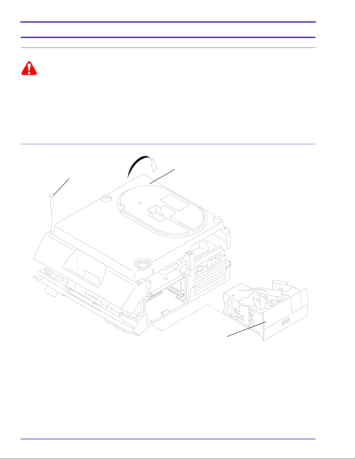
Replacing the LOWER HOUSING ASSEMBLY
Warning
Dangerous Voltage
[1] Disconnect the main power.
[2] Remove the PROJECTION LENS.
[3] Remove the LAMP MODULE ASSEMBLY.
[4] Remove the 6
HOUSING ASSEMBLY.
[5] Pull the LOWER HOUSING ASSEMBLY off the TOP HOUSING.
Installing the LOWER HOUSING ASSEMBLY
Torx
SCREWS (for N.P. models) (or 6
SCREW (6)
Phillips SCREWS for Painted Models) from the LOWER
LOWER HOUSING
A100_0012HCA
A100_0012HA
[1] Do the replacement procedure for the LOWER HOUSING ASSEMBLY in reverse order.
4 30APR96 – SM4530-1
LAMP MODULE
Page 5
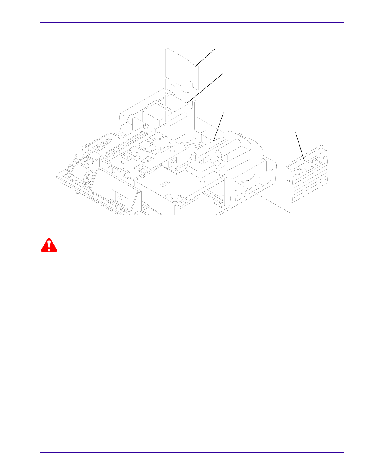
Replacing the FAN SHAFT ASSEMBLY
Replacements and Installations
WIRE TIE (not shown)
BR and KK models
BLOWER COVER WIRE TIE
GRILLE ASSEMBLY
A100_0013HCA
A100_0013HA
Warning
Dangerous Voltage
[1] Disconnect the main power.
[2] Do the replacement procedure for the LOWER HOUSING ASSEMBLY.
[3] Cut the 3 WIRE TIES:
• 1 on BLOWER COVER wires
• 2 on SMALL CIRCUIT BOARD between the MOTOR and MECHANISM ASSEMBLY
[4] Disconnect the 2 wires from the CYCLE SOLENOID on the SMALL CIRCUIT BOARD.
[5] Pull the SMALL CIRCUIT BOARD up.
[6] Remove the
[7] Lift the GRILLE ASSEMBLY in front of the BLOWER COVER ASSEMBLY up.
[8] Loosen the
[9] Lift the LOWER LIGHT BAFFLE ASSEMBLY off the TAB on the BLOWER COVER ASSEMBLY.
[10] Remove the 2 long
Torx SCREW from the BLOWER COVER ASSEMBLY.
Torx
SCREW on the right track of the LOWER LIGHT BAFFLE ASSEMBLY appoximately half way.
Torx
SCREWS from the BLOWER COVER ASSEMBLY.
SM4530-1 – 30APR96 5
Page 6
SERVICE MANUAL
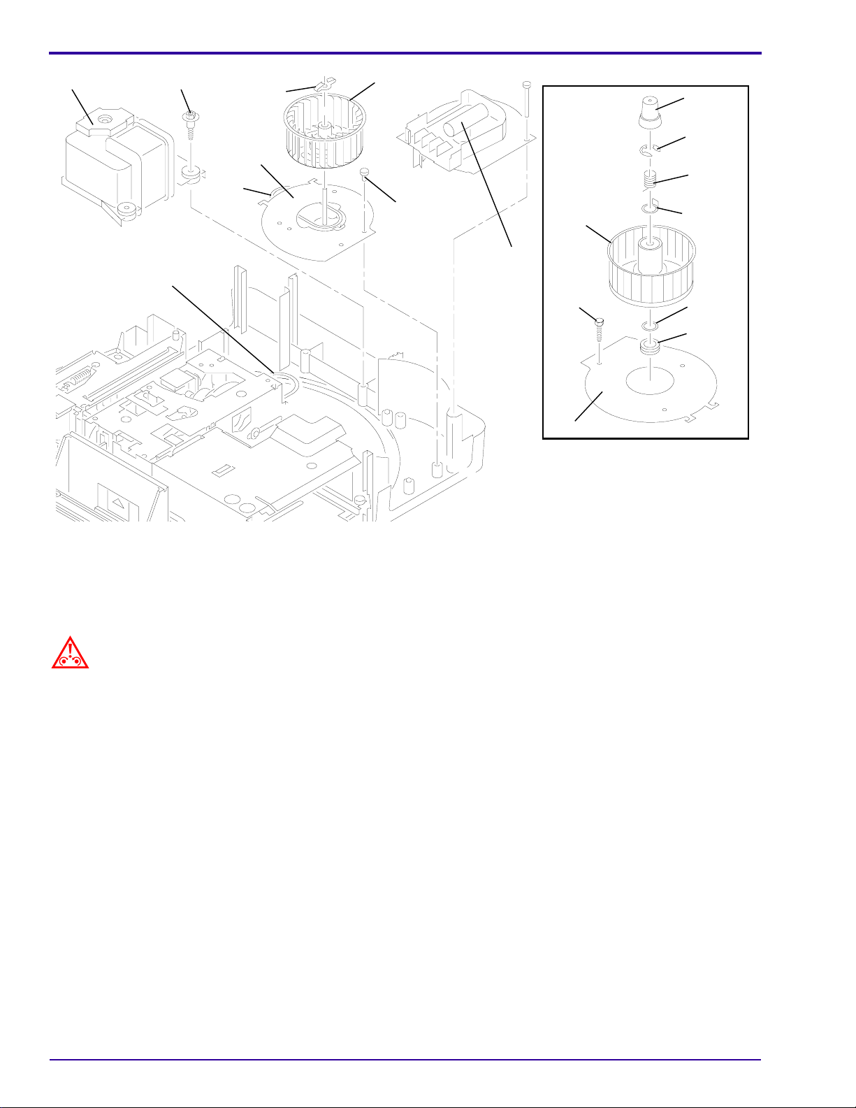
MOTOR
SCREW
MECHANISM
BELT
RETAINER
CLIP
FAN PLATE
ASSEMBLY
FAN
BELT
FAN
SCREW (3)
BLOWER
ASSEMBLY
FAN
SCREW
FAN PLATE
Painted PROJECTOR
FAN CAP
E-RING
SPRING
WASHER
WASHER
CORK
WASHER
A008_0172HCA
A008_0172HA
[11] Lift the BLOWER COVER ASSEMBLY up.
[12] Remove the 3
Hex
1/4 in. SCREWS from the MOTOR.
[13] Lift the MOTOR until you observe the FAN BELT and MECHANISM BELT.
[14] Remove the FAN BELT and MECHANISM BELT off the MOTOR PULLEY. Use SPRING HOOK TL-1165.
Caution
Move the MOTOR to allow access to the parts; wires are still connected to the MOTOR. Do not cause damage to
the MOTOR wires.
[15] N.P. only: Remove the RETAINER CLIP from the FAN SHAFT.
[16] Painted Models only: Remove the FAN CAP, E-RING, SPRING, and WASHER.
[17] Pull the FAN up and off the FAN SHAFT to allow access to the FAN BELT.
[18] Remove the FAN BELT.
[19] N.P. only: Remove the 3
[20] Lift and remove the FAN SHAFT ASSEMBLY.
Torx
SCREWS from the FAN SHAFT ASSEMBLY.
6 30APR96 – SM4530-1
Page 7
Installing the FAN SHAFT ASSEMBLY
Replacements and Installations
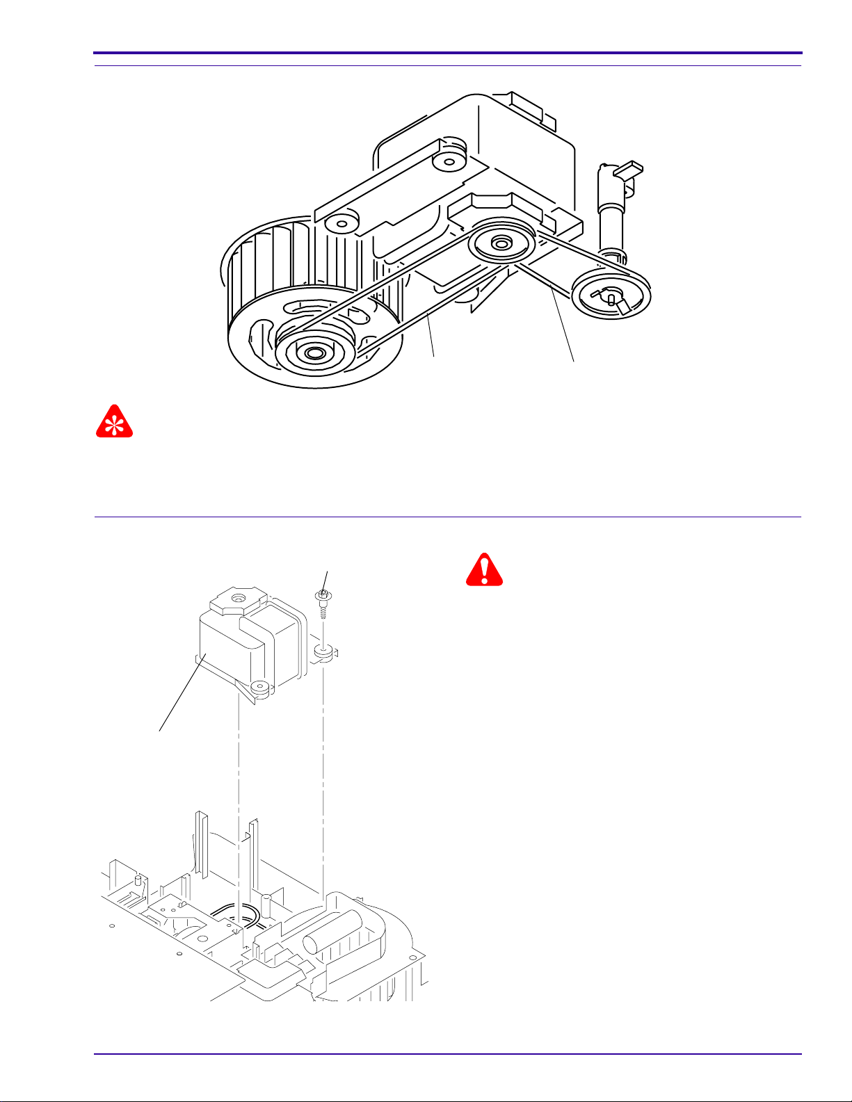
FAN BELT
MECHANISM BELT
A091_4015BCA
A091_4015BA
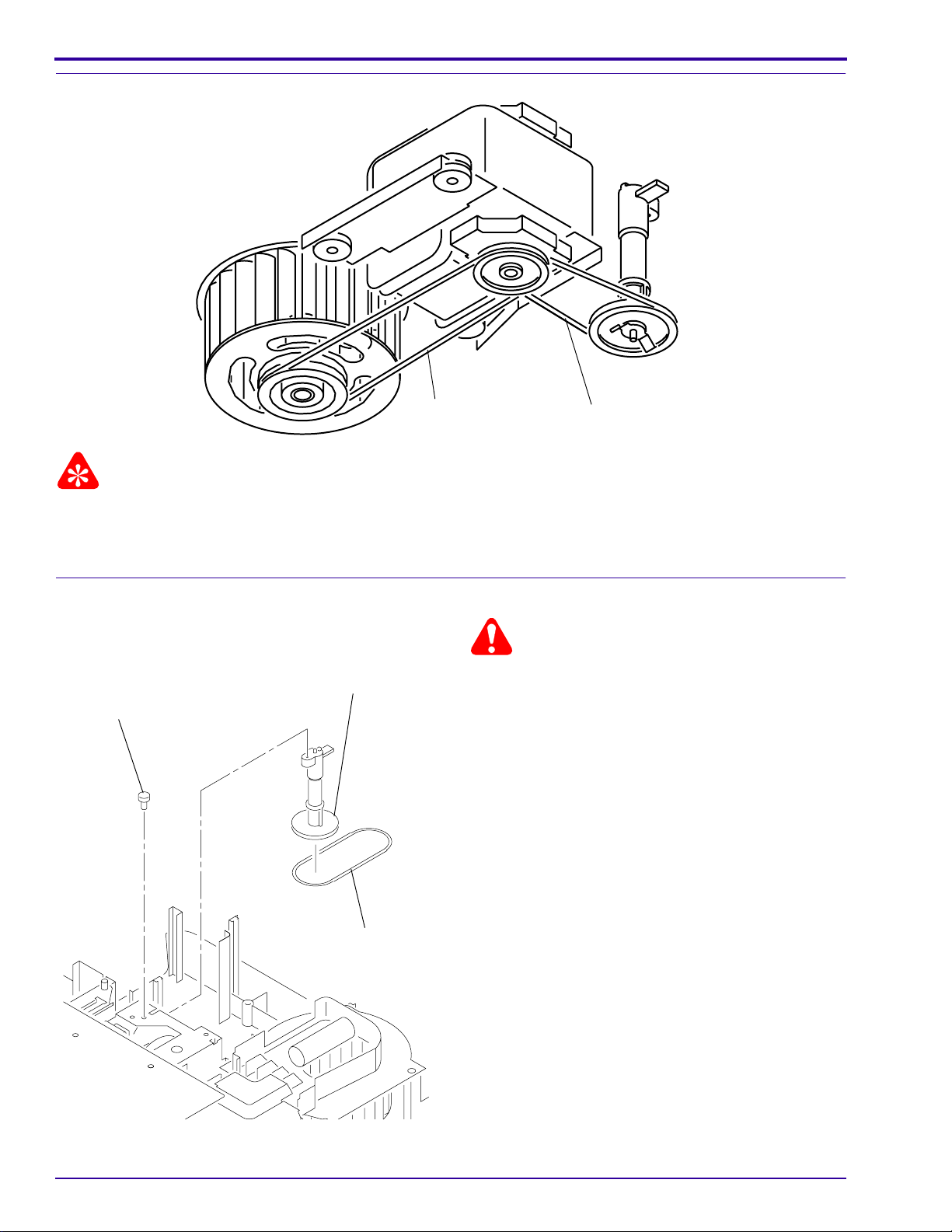
Important
When installing the FAN and MECHANISM BELTS, install the MECHANISM BELT on the small MOTOR PULLEY,
and the FAN BELT on the large MOTOR PULLEY.
[1] Do the removal procedure for the FAN BELT and SHAFT in reverse order.
Replacing the MOTOR
SCREW (3)
Warning
Dangerous Voltage
[1] Disconnect the main power.
[2] Do the replacement procedure for the LOWER
HOUSING ASSEMBLY.
[3] Disconnect all wires from the MOTOR.
[4] Cut the 2 WIRE TIES on the SMALL CIRCUIT
BOARD between the MOTOR and MECHANISM
MOTOR
ASSEMBLY.
[5] Disconnect the 2 wires from the CYCLE
SOLENOID on the SMALL CIRCUIT BOARD.
[6] Pull the SMALL CIRCUIT BOARD up.
[7] Disconnect all wires on the MOTOR.
[8] Remove3
Hex
1/4in.SCREWSfromthe MOTOR.
[9] LifttheMOTORup to allow access to the FANand
MECHANISM BELTS.
[10] Remove the FAN and MECHANISM BELTS from
the MOTOR PULLEY.
[11] Remove the MOTOR.
A091_4016GCA
A091_4016GA
SM4530-1 – 30APR96 7
Page 8
SERVICE MANUAL
Installing the MOTOR
FAN BELT
MECHANISM BELT
A091_4015BCA
A091_4015BA
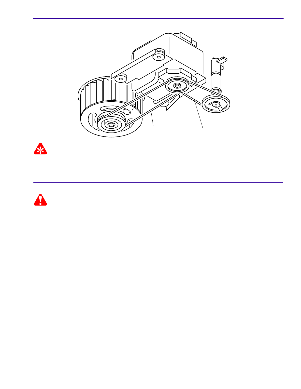
Important
When installing the FAN and MECHANISM BELTS, install the MECHANISM BELT on the small MOTOR PULLEY,
and the FAN BELT on the large MOTOR PULLEY.
[1] Do the replacement procedure for the MOTOR in reverse order.
Replacing the WORM PULLEY and MECHANISM BELT
Warning
WORM PULLEY
SCREW
MECHANISM
BELT
Dangerous Voltage
[1] Disconnect the main power.
[2] Do the replacement procedure for the LOWER
HOUSING ASSEMBLY.
[3] Do the replacement procedure for the MOTOR
except do not disconnect the wires from the
MOTOR.
[4] Remove the
Torx
SCREW (on N.P. models) (or
HexSCREW on PaintedModels)from the WORM
PULLEY ASSEMBLY.
[5] Move the TAB on the WORM PULLEY
ASSEMBLY out.
[6] Remove the WORM PULLEY ASSEMBLY and
MECHANISM BELT.
A091_4017GCA
A091_4017GA
8 30APR96 – SM4530-1
Page 9
Installing the WORM PULLEY and MECHANISM BELT
Replacements and Installations
FAN BELT
MECHANISM BELT
A091_4015BCA
A091_4015BA
Important
When installing the FAN and MECHANISM BELTS, install the MECHANISM BELT on the small MOTOR PULLEY,
and the FAN BELT on the large MOTOR PULLEY.
[1] Do the replacement procedure for the WORM PULLEY and MECHANISM BELT in reverse order.
Replacing the THERMAL FUSE ASSEMBLY
Warning
Dangerous Voltage
[1] Disconnect the main power.
[2] Do the replacement procedure for the LOWER HOUSING ASSEMBLY.
[3] Cut and remove the necessary WIRE TIES.
[4] Remove the black wire from the THERMAL FUSE ASSEMBLY on the POWER SWITCH.
[5] Remove the gray wire from the THERMAL FUSE ASSEMBLY from the POWER CORD.
[6] Loosen the
[7] Pull the THERMAL FUSE ASSEMBLY out of hole of the LOWER LIGHT BAFFLE ASSEMBLY.
Torx
SCREW on the PREHEAT DUCT approximately half way.
SM4530-1 – 30APR96 9
Page 10

SERVICE MANUAL
Installing the THERMAL FUSE ASSEMBLY
SCREW
PRE-HEAT DUCT
[1] Do the replacement procedure for the THERMAL
FUSE ASSEMBLY in reverse order.
A100_0015GCA
A100_0015GA
THERMAL FUSE
POWER SWITCH
10 30APR96 – SM4530-1
Page 11
Replacing the LAMP MODULE RECEPTACLE
SCREW (2)
LOWER LIGHT BAFFLE
Replacements and Installations
PRE-HEAT DUCT
SCREW (2)
LAMP MODULE
RECEPTACLE
BLOWER COVER
ASSEMBLY
A100_0016HCA
A100_0016HA
SCREW (not shown)
Warning
Dangerous Voltage
[1] Disconnect the main power.
[2] Do the replacement procedure for the LOWER HOUSING ASSEMBLY.
[3] Cut and remove the necessary WIRE TIES.
[4] Remove the 2
[5] Loosen the
Torx
SCREWS on the left side of the LOWER LIGHT BAFFLE ASSEMBLY.
Torx
SCREW on the right side of the LOWER LIGHT BAFFLE ASSEMBLY approximately 1/2 way.
[6] Lift and remove the LOWER LIGHT BAFFLE ASSEMBLY.
[7] Lift the GRILLE ASSEMBLY up.
[8] Remove the 2 long
Torx
from the BLOWER COVER ASSEMBLY.
[9] Lift the BLOWER COVER ASSEMBLY up.
[10] Lift and move the PREHEAT DUCT up.
[11] Toremovethe LAMP MODULE RECEPTACLE from the PREHEAT DUCT, compressthe 2 TABS on the LAMP
MODULE RECEPTACLE.
Installing the LAMP MODULE RECEPTACLE
Warning
Dangerous Voltage
[1] Disconnect the main power.
[2] Do the replacement procedure for the LAMP MODULE RECEPTACLE in reverse order.
SM4530-1 – 30APR96 11
Page 12
SERVICE MANUAL
Replacing the CYCLE SOLENOID ASSEMBLY
CYCLE SOLENOID
CYCLE
SOLENOID
PLUNGER
SCREW (2)
A100_0017GCA
A100_0017GA
Warning
Dangerous Voltage
[1] Disconnect the main power.
[2] Do the replacement procedures for the LOWER
HOUSING ASSEMBLY and the MOTOR.
[3] Cut and remove the necessary WIRE TIES.
[4] Disconnect the 2 wires from the CYCLE
SOLENOID on the SMALL CIRCUIT BOARD.
[5] Pull the SMALL CIRCUIT BOARD up.
[6] Remove the
HexSCREW forPaintedModels) from the WORM
PULLEY SHAFT.
[7] Move the TAB on the WORM PULLEY
ASSEMBLY out of the MECHANISM ASSEMBLY.
[8] Lift and remove the WORM PULLEY ASSEMBLY.
[9] Remove the 2
CYCLE SOLENOID GROMMETS.
[10] Pull the CYCLE SOLENOID ASSEMBLY up and
out.
[11] If necessary, remove the CYCLE SOLENOID
PLUNGER ASSEMBLY.
Torx
SCREW (for N.P. models) (or
Torx
1/4 in. SCREWS from the 2
Installing the CYCLE SOLENOID ASSEMBLY
Important
Do the adjustment for the CYCLE SOLENOID ASSEMBLY. See the Adjustments section.
[1] Do the replacement procedure for the CYCLE SOLENOID ASSEMBLY in reverse order.
12 30APR96 – SM4530-1
Page 13
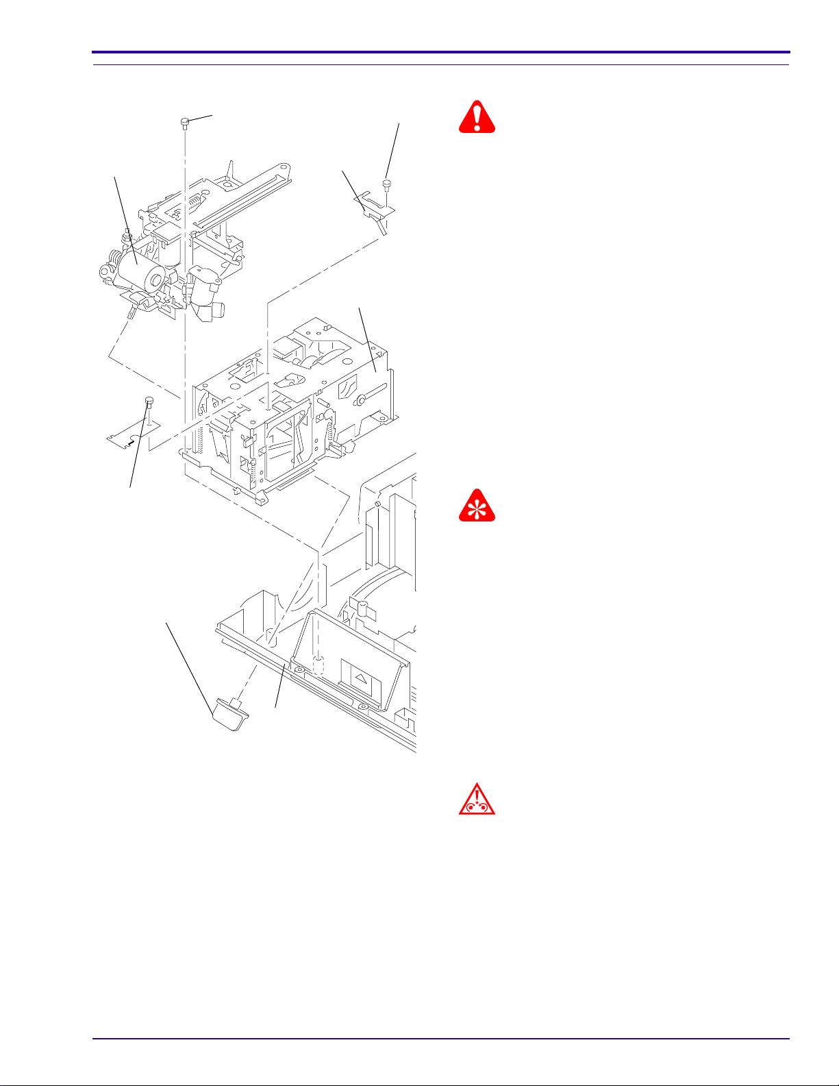
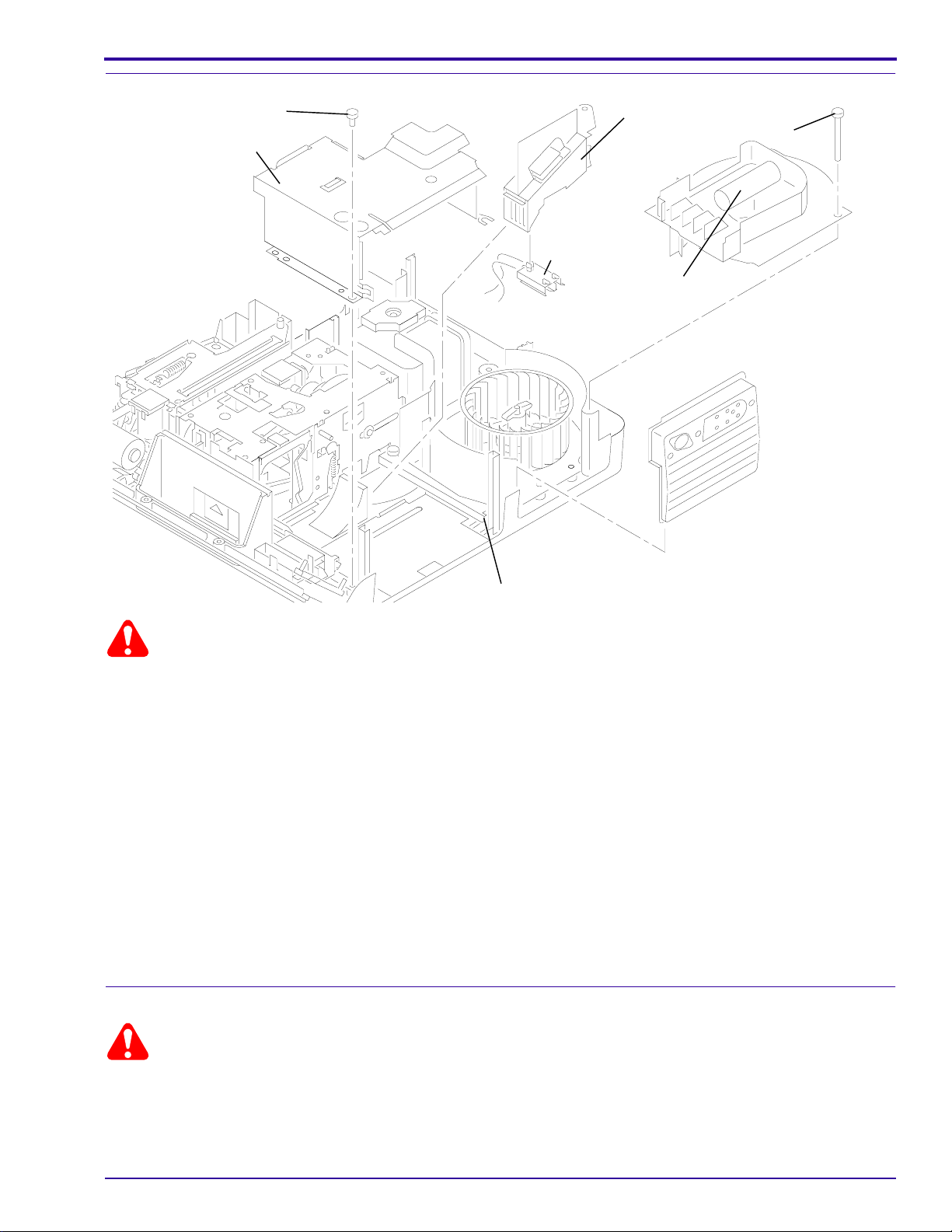
Replacing the MECHANISM ASSEMBLY
Replacements and Installations
LENS
MOUNT
SCREW
FOCUS KNOB
A091_4022CCA
A091_4022CA
SCREW (3)
AUTO FOCUS
DEFEAT SWITCH
(not shown)
DARK
SHUTTER
SWITCH
MECHANISM
ASSEMBLY
SCREW
Warning
Dangerous Voltage
[1] Disconnect the main power.
[2] Do the replacement procedure for the LOWER
HOUSING ASSEMBLY.
[3] Cut and remove the necessary WIRE TIES.
[4] Disconnect the 2 wires from the CYCLE
SOLENOID on the SMALL CIRCUIT BOARD.
[5] Pull the SMALL CIRCUIT BOARD up.
[6] Disconnect all wires connected to the
MECHANISM ASSEMBLY:
• 1 yellow wire from CYCLE SWITCH
• 1 orange wire from WIRE NUT
• 1 green wire from POWER CORD
• 2 green ground wires from the lower
MECHANISM ASSEMBLY
[7] Remove the FOCUS KNOB from the FRONT
PANEL.
Important
ForAuto-Focusmodels only, disconnect the short, gray
wire connected to the AUTO-FOCUS DEFEAT
SWITCH.
[8] Remove the 3
MOUNT ASSEMBLY.
[9] Lift and move the LENS MOUNT ASSEMBLY up.
[10] Do the replacement procedure for the MOTOR.
[11] Remove the 3
MECHANISM ASSEMBLY.
[12] Loosen the SCREW on the STABILIZER WALL
approximately half way.
[13] Remove the SCREW from the DARK SHUTTER
SWITCH and remove the SWITCH.
Torx
SCREWS from the LENS
Torx
SCREWS from the
Caution
There might be a bind between the SELECT LEVER
and the SELECT BUTTON when removing the
MECHANISM ASSEMBLY. Do not use force; this
might cause damage to the SELECT BUTTON.
[14] Remove the MECHANISM ASSEMBLY.
SM4530-1 – 30APR96 13
Page 14
SERVICE MANUAL
Installing the MECHANISM ASSEMBLY
Important
To insert the SELECTBUTTON into the holein the SELECT LEVERwhen installing the MECHANISM ASSEMBLY,
hold the SELECT BUTTON completely down.
[1] Do the removal procedure for the MECHANISM ASSEMBLY in reverse order.
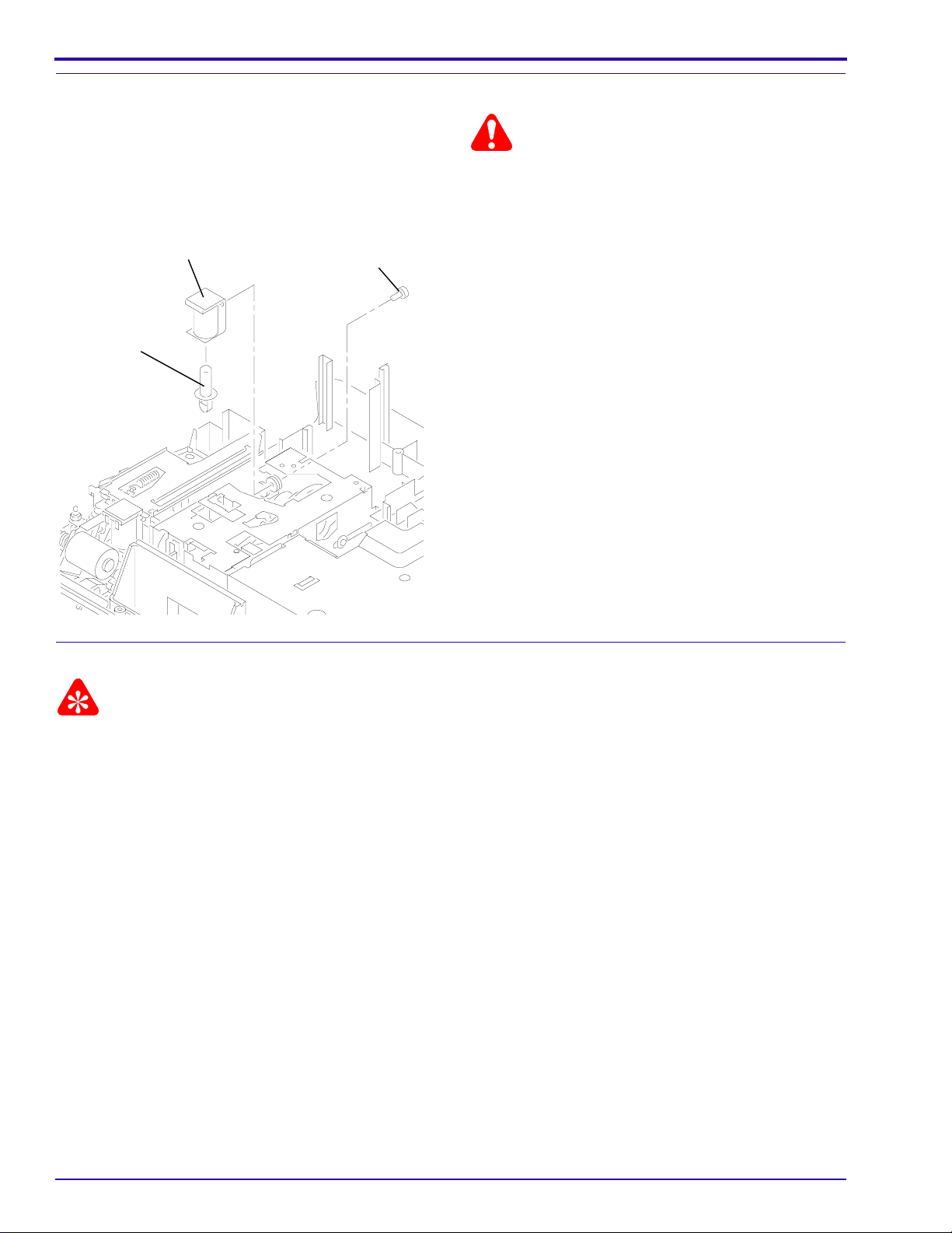
Replacing the AUTO-FOCUS BRACKET ASSEMBLY
SCREW
CYCLE
SOLENOID
AUTO
FOCUS
BRACKET
ASSEMBLY
SCREW
SCREW (2)
WORM
PULLEY
A091_4023BCA
A091_4023BA
Warning
Dangerous Voltage
[1] Disconnect the main power.
[2] Do the replacement procedure for the LOWER HOUSING ASSEMBLY.
[3] Cut and remove the necessary WIRE TIES.
[4] Disconnect the 2 wires from the CYCLE SOLENOID on the SMALL CIRCUIT BOARD.
[5] Pull the SMALL CIRCUIT BOARD up.
[6] Do the replacement procedure for the MECHANISM ASSEMBLY.
[7] Remove the
[8] Remove the WORM PULLEY.
[9] Remove the 2
[10] Remove the CYCLE SOLENOID.
[11] Remove the
[12] Pull and remove the AUTO-FOCUS BRACKET ASSEMBLY through the hole where the CYCLE SOLENOID
was.
Torx
SCREW (on N.P. models) (or Hex SCREW on Painted Models) from the WORM PULLEY.
Hex
SCREWS from the CYCLE SOLENOID.
Phillips
SCREW from the AUTO-FOCUS BRACKET ASSEMBLY.
Installing the AUTO-FOCUS BRACKET ASSEMBLY
[1] Do the replacement procedure for the AUTO-FOCUS BRACKET ASSEMBLY in reverse order.
14 30APR96 – SM4530-1
Page 15
Replacements and Installations
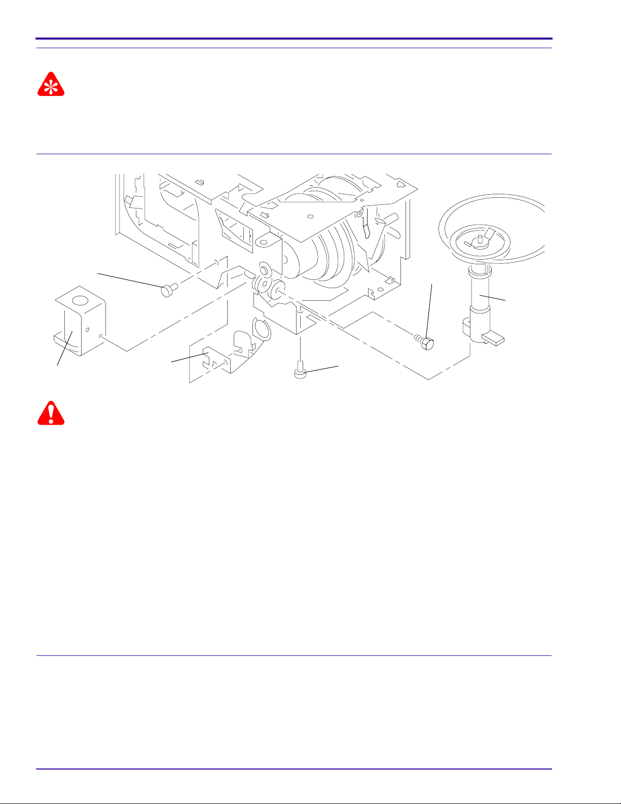
Replacing the CAM STACK ASSEMBLY and CYCLE LEVER ASSEMBLY
LIFT LEVER
SHAFT
STYLE 1
RETARD
SPRING
E-RING
BEARING
STYLE 2
RETARD
SPRING
LIFT LEVER
BEARING
CAM STACK ASSEMBLY
NUT
E-RING
A008_0173HCA
A008_0173HA
Warning
Dangerous Voltage
[1] Disconnect the main power.
[2] Do the replacement procedure for the MECHANISM ASSEMBLY.
[3] Remove the INDEXER LEVER ASSEMBLY from the TOP PLATE of the MECHANISM ASSEMBLY.
[4] Remove the
ASSEMBLY.
[5] Remove the WORM PULLEY ASSEMBLY.
[6] Remove the DIRECTION LEVER LINK from the DIRECTION LEVER.
[7] Remove the DIRECTION LEVER SPRING from the DIRECTION LEVER.
[8] Disconnect the LIFT LEVER SPRING from LIFT LEVER on the TOP PLATE of the MECHANISM ASSEMBLY.
[9] Remove the RETARD SPRING.
[10] Remove the 7
the MECHANISM ASSEMBLY.
[11] Remove the TOP PLATE.
Torx
SCREW (on N.P. models) (or Hex SCREW on Painted Models) from the WORM PULLEY
Torx
SCREWS (on N.P. models) (or Hex SCREWS on Painted Models) from the TOP PLATE of
SM4530-1 – 30APR96 15
Page 16

SERVICE MANUAL
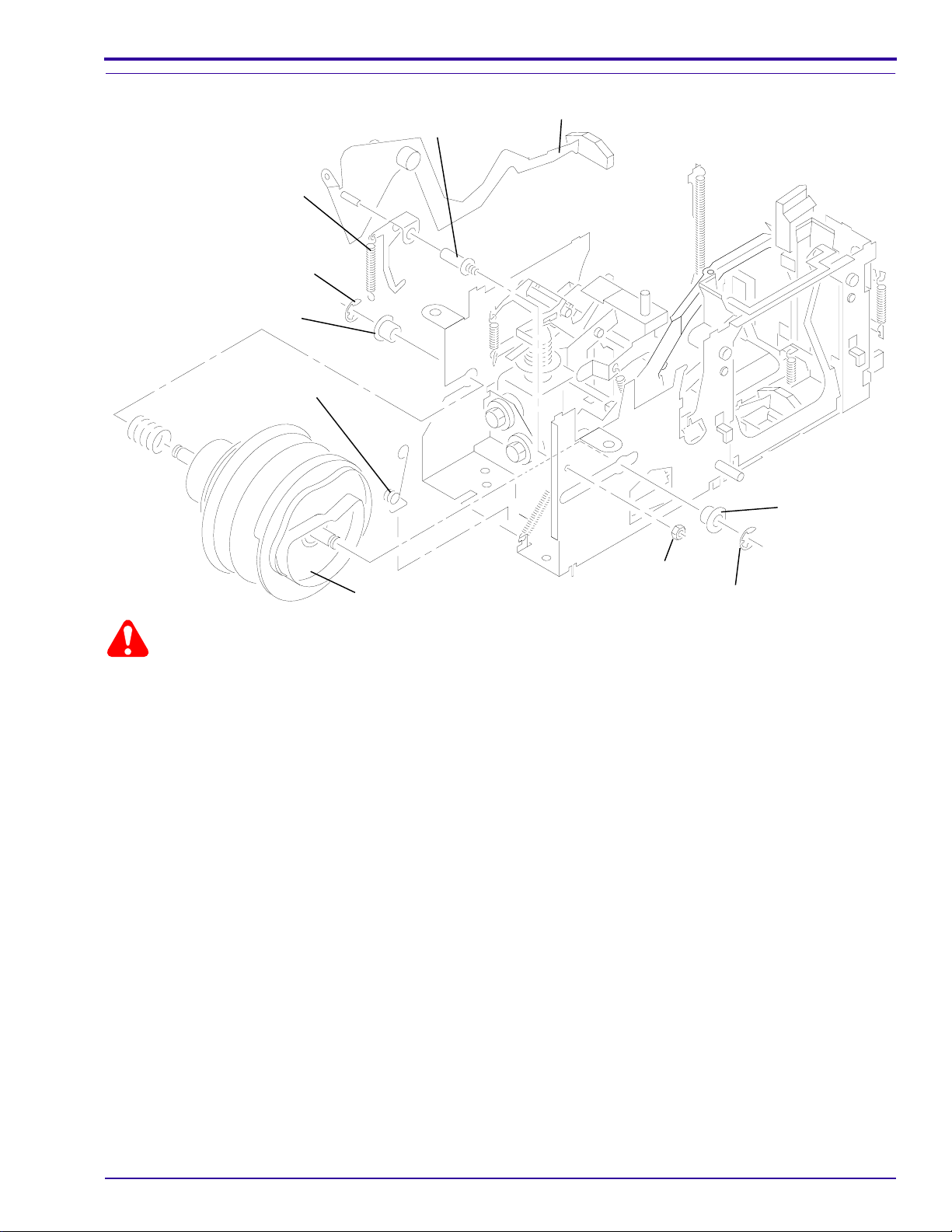
[12] Remove the LIGHT BAFFLE.
SELECT LEVER
SELECT
LEVER
SPRING
E-RING
BEARING
LIFT LEVER
SHAFT
LIFT LEVER
BEARING
NUT
CAM STACK ASSEMBLY
TAB
E-RING
[13] Remove the NUT from the LIFT LEVER SHAFT.
[14] Remove the LIFT LEVER and SHAFT.
[15] Remove the 2 E-RINGS from the 2 CAM SHAFT BEARINGS.
[16] Remove the 2 CAM SHAFT BEARINGS.
[17] Press and hold the SELECT LEVER down.
[18] Remove the CAM STACK ASSEMBLY.
[19] Disconnect the SELECT LEVER SPRING from the TAB and remove the SELECT LEVER.
A008_0174HCA
A008_0174HA
16 30APR96 – SM4530-1
Page 17
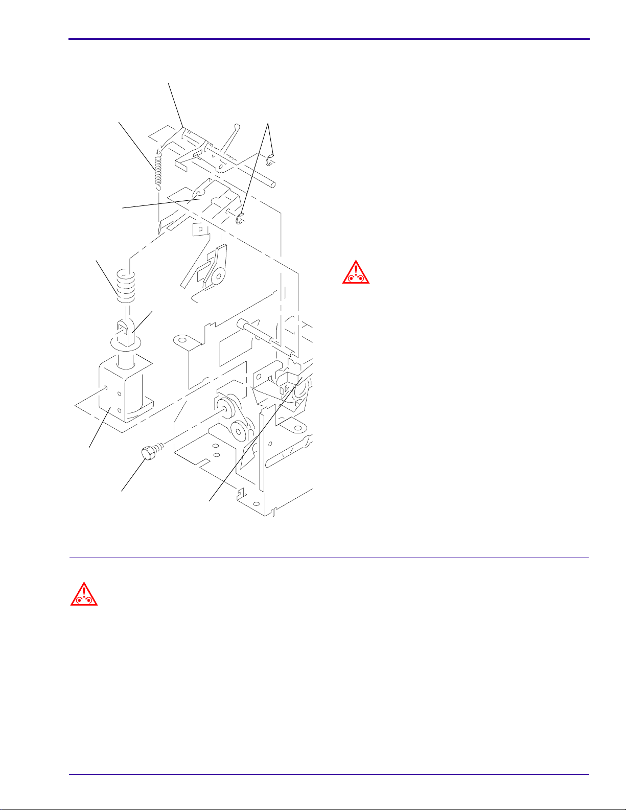
HALF-CYCLE
LEVER SPRING
CYCLE
LEVER
PLUNGER
SPRING
HALF-CYCLE
LEVER
PLUNGER
E-RING (2)
Replacements and Installations
[20] Remove the 2 SCREWS from the CYCLE
SOLENOID.
[21] Remove the CYCLE SOLENOID.
[22] Slide the PLUNGER and PLUNGER SPRING off
the CYCLE LEVER.
[23] Remove the HALF CYCLE SPRING between the
CYCLE LEVER ASSEMBLY and the HALF
CYCLE LEVER.
[24] Disconnect the INDEX LEVER SPRING from the
MECHANISM ASSEMBLY.
[25] Push the INDEX LEVER back.
[26] Remove the 2 E-RINGS:
• 1 on the CYCLE LEVER ASSEMBLY
• 1 on the HALF CYCLE LEVER
Caution
Keep both the CYCLE LEVER ASSEMBLY and the
HALF CYCLE LEVER together and observe the
orientation of both LEVERS.
[27] Slide both the CYCLE LEVER and HALF CYCLE
LEVER off the SHAFT.
CYCLE
SOLENOID
SCREW (2)
INDEX LEVER
and SPRING
(not shown)
A091_0009CCA
A091_0009CA
Installing the CAM STACK ASSEMBLY and CYCLE LEVER ASSEMBLY
Caution
Keep both the CYCLE LEVER ASSEMBLY and the HALF CYCLE LEVER together and observe the orientation of
both LEVERS.
[1] Do the replacement procedure for the CAM STACK ASSEMBLY and CYCLE LEVER ASSEMBLY in reverse
order.
SM4530-1 – 30APR96 17
Page 18

SERVICE MANUAL
Replacing the LAMP SOCKET TERMINAL ASSEMBLY, N.P.
SCREW
LAMP DOOR
PLATE ASSEMBLY
PROJECTOR
LAMP
LAMP
EJECTOR
LAMP SOCKET
TERMINAL
ASSEMBLY
Warning
Dangerous Voltage
[1] Disconnect the main power.
[2] Remove the LAMP MODULE.
[3] Removethe PROJECTION LAMP from the LAMP
MODULE.
[4] Remove the SCREW from the LAMP DOOR
PLATE ASSEMBLY.
[5] Release the 2 TABS on the bottom side of the
LAMP MODULE next to the LAMP MODULE
DOOR.
[6] Remove the LAMP DOOR PLATE ASSEMBLY.
Caution
Remove the CONDENSER LENS and HEAT
ABSORBING GLASS and set the parts on a clean
cloth. Do not set on a cold surface; this will cause
damage to the parts.
[7] Remove the LAMP EJECTOR.
[8] Remove the LAMP SOCKET TERMINAL
ASSEMBLY.
CONDENSER
LENS
TAB (2)
HEAT ABSORBING
GLASS
A091_0018CCA
A091_0018CA
Installing the LAMP SOCKET TERMINAL ASSEMBLY
[1] Do the replacement procedure for the LAMP SOCKET TERMINAL ASSEMBLY in reverse order.
18 30APR96 – SM4530-1
Page 19

Replacements and Installations
Replacing the LAMP SOCKET TERMINAL ASSEMBLY, Painted Models
E-RING
SPRING
WASHER
PROJECTOR
LAMP
LAMP
EJECTOR
6 TABS
CONDENSER
HOLDER
SOCKET PIN
LAMP SOCKET
TOP PLATE
LAMP
BRACKET
SCREW
HEAT GLASS
CONDENSER
LENS
A008_0171DCA
A008_0171DA
[1] Disconnect the main power.
[2] Remove:
• LAMP MODULE
• PROJECTION LAMP for the LAMP MODULE from the LAMP MODULE
• SCREW and lift the CONDENSER LENS HOLDER up
• CONDENSER LENS and HEAT GLASS
• RETAINING RING
• SPRING WASHER
• SOCKET PIN
SM4530-1 – 30APR96 19
Page 20

SERVICE MANUAL
Caution
The TABS could break.
[3] Bend the 3 TABS of the LAMP BRACKET ASSEMBLY.
[4] Lift the top of the LAMP BRACKET ASSEMBLY up.
[5] Rotate and push the LAMP TERMINAL ASSEMBLY until it releases.
[6] Remove the LAMP TERMINAL ASSEMBLY.
Installing the LAMP SOCKET TERMINAL ASSEMBLY, Painted Models
[1] Do the replacementprocedure for the LAMPSOCKET TERMINAL ASSEMBLY in reverse order and checkthe
following during installation:
• Check that the LAMP EJECTOR is aligned correctly before you install the LAMP TERMINAL ASSEMBLY.
• Check that the LAMP TERMINAL ASSEMBLY wires are aligned correctly.
• Bend the 3 TABS down until they are flush with the top of the LAMP BRACKET ASSEMBLY. If the TABS
break, use TOP PLATE SCREW 785130 to install a new TAB.
Replacing the LENS MOUNT ASSEMBLY - Auto Focus Model
SCREW (3)
LENS MOUNT
ASSEMBLY
Dangerous Voltage
Warning
[1] Disconnect the main power.
[2] Do the replacement procedure for the LOWER
HOUSING ASSEMBLY.
[3] Remove the FOCUS KNOB.
[4] Remove the short, gray wire connected to the
AUTO-FOCUS DEFEAT SWITCH.
Important
It is necessary to push the AUTO-FOCUS BRACKET
backward and forward to allowaccess tothe SCREWS
on the LENS MOUNT ASSEMBLY.
[5] Remove the 3 SCREWS from the LENS MOUNT
ASSEMBLY.
[6] Lift and remove the LENS MOUNT ASSEMBLY.
A100_0019GCA
A100_0019GA
Installing the LENS MOUNT ASSEMBLY - Auto Focus Models
[1] Do the replacement procedure for the LENS MOUNT ASSEMBLY in reverse order.
20 30APR96 – SM4530-1
Page 21

Replacing the LENS MOUNT ASSEMBLY - Non Auto Focus Model
SCREW (3)
LENS MOUNT
ASSEMBLY
Dangerous Voltage
Warning
[1] Disconnect the main power.
[2] Do the replacement procedure for the LOWER
HOUSING ASSEMBLY.
[3] Remove the FOCUS KNOB.
[4] Remove the 3 SCREWS from the LENS MOUNT
ASSEMBLY.
[5] Lift and remove the LENS MOUNT ASSEMBLY.
Replacements and Installations
A100_0019GCA
A100_0019GA
Installing the LENS MOUNT ASSEMBLY - Non Auto Focus Model
[1] Do the replacement procedure for the LENS MOUNT ASSEMBLY in reverse order.
SM4530-1 – 30APR96 21
Page 22

SERVICE MANUAL
Replacing the AUTO-FOCUS SWITCH ASSEMBLY
AUTO FOCUS
MOTOR BRACKET
LOCKING
TAB
AUTO FOCUS
SWITCH LEVER
AUTO FOCUS SWITCH ASSEMBLY
grey, red,
and black
wires
A091_4028GCA
A091_4028GA
Warning
Dangerous Voltage
[1] Disconnect the main power.
[2] Do the replacement procedure for the LOWER
HOUSING ASSEMBLY.
[3] Remove the FOCUS KNOB.
[4] Remove the short, gray wire from the AUTO-
FOCUS DEFEAT SWITCH.
Important
• It is necessary to push the AUTO-FOCUS
BRACKET backward and forward to allow access
to the SCREWS on the LENS MOUNT
ASSEMBLY.
• Keep the AUTO-FOCUS SWITCH LEVER that is
connected to the AUTO FOCUS SWITCH so you
can install it on the new AUTO FOCUS SWITCH.
[5] Remove the 3 SCREWS from the LENS MOUNT
ASSEMBLY.
[6] Lift and remove the LENS MOUNT ASSEMBLY.
[7] Remove the gray, red, and black wires from the
AUTO FOCUS SWITCH ASSEMBLY.
[8] To disconnect and remove the AUTO FOCUS
SWITCH,bendthe LOCKING TABonthe FOCUS
MOTOR BRACKET until it is alignedwith thehole
in the AUTO FOCUS SWITCH.
Installing the AUTO-FOCUS SWITCH ASSEMBLY
Important
Align the 2TABS onthe AUTO-FOCUS SWITCH with the FOCUS MOTORBRACKET, checking that the endof the
AUTO-FOCUSLEVERengageswiththe CYCLE SOLENOID PLUNGER. After the AUTO-FOCUS SWITCH is in the
correct position, bend the LOCKING TAB to hold the AUTO FOCUS SWITCH in place.
[1] Do the replacement procedure for the AUTO-FOCUS SWITCH in reverse order.
22 30APR96 – SM4530-1
Page 23

Replacing the FOCUS SHAFT ASSEMBLY - Auto Focus Models
CLAMP LEVER
SPRING
RACK LEVER
(not shown)
SCREW
Replacements and Installations
FOCUS SHAFT
SPRING
FOCUS SHAFT
FOCUS MOTOR
BRACKET
SPACER
E-RING
PHOTOCELL
BRACKET
SPRING
AUTO-FOCUS
SWITCH
ASSEMBLY
Warning
Dangerous Voltage
[1] Disconnect the main power.
[2] Do the replacement procedure for the LOWER HOUSING ASSEMBLY.
[3] Remove the FOCUS KNOB.
[4] Remove the short, gray wire from the AUTO-FOCUS DEFEAT SWITCH.
SCREW
SCREW
RACK
SOLENOID
PLUNGER
LENS SUPPORT BRACKET
A091_4029HCA
A091_4029HA
Important
It is necessary topush the AUTO-FOCUS BRACKETbackward and forward toallow access to theSCREWS on the
LENS MOUNT ASSEMBLY.
[5] Remove the 3 SCREWS from the LENS MOUNT ASSEMBLY.
[6] Lift and remove the LENS MOUNT ASSEMBLY.
[7] Remove the FOCUS SHAFT SPRING from the LENS MOUNT BRACKET.
[8] Remote models only: Remove the SPRING from the CLAMP LEVER on the LENS MOUNT BRACKET.
[9] Remove the SPRING from the PHOTOCELL BRACKET.
[10] Remove the E-RING and SPACER from the FOCUS SHAFT ASSEMBLY.
[11] Remove the SCREW from the LENS SUPPORT BRACKET.
[12] Lift and remove the LENS SUPPORT BRACKET.
[13] Remote models: Remove the AUTO-FOCUS SWITCH ASSEMBLY.
[14] Remote models: Remove the SCREW from the RACK SOLENOID ASSEMBLY.
[15] Remote models: Remove the RACK SOLENOID ASSEMBLY and PLUNGER.
[16] Remote models: Remove the SCREW from the FOCUS MOTOR BRACKET ASSEMBLY.
SM4530-1 – 30APR96 23
Page 24

SERVICE MANUAL
[17] Remove the FOCUS MOTOR BRACKET ASSEMBLY.
[18] Push the RACK LEVER away from the FOCUS SHAFT ASSEMBLY.
[19] Remove the FOCUS SHAFT ASSEMBLY.
Installing the FOCUS SHAFT ASSEMBLY
Important
Do the adjustments for thePHOTOCELL NULL and AUTO-FOCUS CLAMP after installation. See the Adjustments
section.
Replacing the FOCUS SHAFT ASSEMBLY - Non Auto-Focus Models
SCREW
FOCUS SHAFT
ASSEMBLY
FOCUS SHAFT
SPRING
FOCUS MOTOR
BRACKET
SPACER
E-RING
SCREW
Warning
Dangerous Voltage
[1] Disconnect the main power.
[2] Do the replacement procedure for the LOWER HOUSING ASSEMBLY.
[3] Remove the FOCUS KNOB.
[4] Remove the 3 SCREWS from the LENS MOUNT ASSEMBLY.
[5] Lift and remove the LENS MOUNT ASSEMBLY.
[6] Remove the FOCUS SHAFT SPRING from the LENS MOUNT BRACKET.
[7] Remove the E-RING and SPACER from the FOCUS SHAFT ASSEMBLY.
[8] Remove the SCREW from the LENS SUPPORT BRACKET.
[9] Lift and remove the LENS SUPPORT BRACKET.
[10] Remove the E-RING and SPACER from the FOCUS SHAFT ASSEMBLY.
[11] Remove the SCREW from the FOCUS MOTOR BRACKET ASSEMBLY.
LENS SUPPORT
BRACKET
A091_0020HCA
A091_0020HA
24 30APR96 – SM4530-1
Page 25

Replacements and Installations
[12] Remove the FOCUS MOTOR BRACKET ASSEMBLY.
[13] Remove the FOCUS SHAFT ASSEMBLY.
Installing the FOCUS SHAFT ASSEMBLY
[1] Do the replacement procedure for the FOCUS SHAFT ASSEMBLY in reverse order.
SM4530-1 – 30APR96 25
Page 26

SERVICE MANUAL
Section 2: Adjustments
Adjustment Specification
Use T-BAR TL-3003 to bend the CYCLE LEVER to adjust the CYCLE SOLENOID.
Adjusting the CYCLE SOLENOID
MECHANISM
ASSEMBLY
T-BAR
TL-3003
CYCLE
BAR
Warning
Dangerous Voltage
[1] Connect the main power.
Important
• The CYCLE SOLENOID must operate correctly to do this adjustment.
• The MECHANISM ASSEMBLY does not have to be removed to do this adjustment.
[2] Do the removal for the LOWER HOUSING ASSEMBLY.
[3] Bend the CYCLE LEVER up or down. Use T-BAR TL-3003.
[4] Energize the projector.
[5] Press the “FORWARD” BUTTON to check for correct operation.
[6] Press the “REVERSE” BUTTON to check for correct operation.
[7] Do the steps above until the FORWARD and REVERSE functions operates correctly.
A091_0007HCA
A091_0007HA
26 30APR96 – SM4530-1
Page 27

Adjustments
Adjustment Specification
This adjustment adjusts the strobe and timing of the INDEXER LEVER. Use TL-3000. The gate edge of the black
plastic of the INDEXER LEVER should be between the 2 holes at position 2.
Adjusting the INDEXER LEVER ASSEMBLY
MECHANISM
ASSEMBLY
MECHANISM
RUNNING FIXTURE
TOP PLATE
Bend
here.
position 1 position 2
A091_0008HCA
A091_0008HA
Warning
Dangerous Voltage
[1] Disconnect the main power.
[2] Do the removal for the MECHANISM ASSEMBLY.
[3] Place the MECHANISM ASSEMBLY on the MECHANISM RUNNING FIXTURE TL-3000.
[4] Check the alignment of the INDEXER LEVER with the hole in the TOP PLATE ASSEMBLY at Position 1.
[5] Bend the INDEXER LEVER to the correct position.
[6] Check the travel of the INDEXER LEVER in the FORWARD position. When the INDEXER LEVER moves in
the FORWARD position, the gate edge of the black plastic should be between the 2 holes at Position 2.
[7] Bend the INDEXER LEVER until you reach the correct position.
Adjustment Specification
Use TL-3000 MECHANISM RUNNING FIXTURE. Use TL-3001 to measure the height of the SLIDE LIFT LEVER.
The LEVER should make contact with the low surface of TL-3001. The LEVER should not make contact with the
high surface of TL-3001.
SM4530-1 – 30APR96 27
Page 28

SERVICE MANUAL
Adjusting the SLIDE LIFT LEVER MANUAL
SLIDE LIFT
LEVER GUAGE
TL-3001
Warning
Dangerous Voltage
[1] Disconnect the main power.
SLIDE LIFT
LEVER
SELECT
LEVER
(not shown)
A091_0016BCA
A091_0016BA
Important
The older style MECHANISM SLIDE LIFT LEVER has an ECCENTRIC on it to do this adjustment.
[2] Do the removal for the MECHANISM ASSEMBLY.
[3] Place the MECHANISM ASSEMBLY on the MECHANISM RUNNING FIXTURE TL-3000.
[4] Press and hold the SELECT LEVER down to move the SLIDE LIFT LEVER to the highest position.
[5] Measure the height of the SLIDE LIFT LEVER. Use SLIDE LIFT LEVER GAUGE TL-3001. The SLIDE LIFT
LEVER should make contact withthe lowsurface of theSLIDE LIFTLEVER GAUGE TL-3001; the SLIDE LIFT
LEVER should not make contact with the high surface of the SLIDE LIFT LEVER
GAUGE TL-3001.
[6] Bend the SLIDE LIFT LEVER until the adjustment is correct.
Adjustment Specification
Use TL-3000 MECHANISM RUNNING FIXTURE. Use TL-3001 to measure the height of the SLIDE LIFT LEVER.
The LEVER should make contact with the low surface of TL-3001. The LEVER should not make contact with the
high surface of TL-3001.
28 30APR96 – SM4530-1
Page 29

Adjusting the SLIDE LIFT LEVER POWER
SLIDE LIFT
LEVER GUAGE
TL-3001
Warning
Dangerous Voltage
[1] Disconnect the main power.
Adjustments
SLIDE LIFT
LEVER
SELECT
LEVER
(not shown)
A091_0016BCA
A091_0016BA
Important
The older style MECHANISM SLIDE LIFT LEVER has an ECCENTRIC on it to do this adjustment.
[2] Do the removal for the MECHANISM ASSEMBLY.
[3] Place the MECHANISM ASSEMBLY on the MECHANISM RUNNING FIXTURE TL-3000.
[4] Energize the MECHANISM FIXTURE.
[5] Press and hold the SELECT LEVER down to move the SLIDE LIFT LEVER to the highest position.
[6] Measure the height of the SLIDE LIFT LEVER. Use SLIDE LIFT LEVER GAUGE TL-3001. The SLIDE LIFT
LEVER should make contact with the low surface of the SLIDE LIFT LEVER GAUGE TL-3001;
the SLIDE LIFT LEVER should not makecontact with the high surfaceof the SLIDE LIFT LEVER GAUGE TL-
3001.
[7] Bend the SLIDE LIFT LEVER until the adjustment is correct.
Adjustment Specification
Make a 5/16 in WRENCH to do this adjustment (see the Tools section). Connect a DIGITAL VOLT METER
betweens PINS 1 and 3 (ZERO POSITION SWITCH). The DVMshould measure • without a TRAY and 0W with a
TRAY installed.
SM4530-1 – 30APR96 29
Page 30

SERVICE MANUAL
Adjusting the ZERO POSITION SWITCH
SPECIAL APPLICATIONS PLUG
4
1
7
6
8
A100_0022ACA
A100_0022AA
ZERO POSITION
SWITCH
Important
It is necessary to make a 5/16 in. WRENCH to do this
adjustment. See the Tools section.
[1] Energize the projector.
2
5
3
NUT
[2] Connect the DIGITAL VOLT METER (DVM)
between PINS 1 and 3 (ZERO POSITION
SWITCH) of the SPECIAL APPLICATIONS
PLUG.
[3] Without a TRAY installed, the DVM should
measure •.
[4] Install a TRAY.
[5] To move the TRAY out of the zero position, press
the “FORWARD” or “REVERSE” BUTTONS; the
DVM should measure 0 W.
[6] If the measurements are not within specification,
adjust the ZERO POSITION SWITCH
ECCENTRIC to specification.
A091_0017GCA
A091_0017GA
Adjustment Specification
Seat AUTO-FOCUS TARGET SLIDE TL-3002 on the GATE MECHANISM. Use TL-3005 or TL-1165 to bend the
AUTO-FOCUS BRACKET ASSEMBLY MIRROR until the image is within the target of the TARGET SLIDE.
30 30APR96 – SM4530-1
Page 31

Adjusting the Focus Light Path - Auto Focus Models
ADJUSTMENT TOOL
TL-3005 or
SPRING HOOK TL-1165
AUTO FOCUS
BRACKET
ASSEMBLY
light path
Adjustments
image
A091_4026HCA
AUTO-FOCUS TARGET SLIDE TL-3002
A091_4026HA
Warning
Dangerous Voltage
[1] Disconnect the main power.
[2] Remove the PROJECTION LENS.
[3] Do the removal for the LOWER HOUSING ASSEMBLY.
Important
It is necessary to make a FAN COVER TOOL. See the Tools section.
[4] Install the FAN COVER TOOL over the FAN area and the LAMP MODULE.
[5] Energize the projector.
[6] Set the projector to the LOW LAMP position.
[7] Install the AUTO-FOCUS TARGET SLIDE TL-3002 until it is fully seated in the GATE MECHANISM.
[8] Look through the PROJECTION LENS hole and observe the focus light path on the AUTO-FOCUS TARGET
SLIDE TL-3002.
[9] Check the position of the image on the AUTO-FOCUS TARGET SLIDE TL-3002.
[10] Bend the AUTO-FOCUS BRACKET ASSEMBLY MIRROR until the image is within the target on the TARGET
SLIDE. Use ADJUSTMENT TOOL TL-3005 or the SPRING HOOK TL-1165.
Adjustment Specification
Use TL-3002 to observe the focus light path and check the light image. Use T-BAR TL-3003 to bend the
PHOTOCELL BRACKET to move the NULL in the center if necessary.
SM4530-1 – 30APR96 31
Page 32

SERVICE MANUAL
Adjusting the NULL
light path
T-BAR
TL-3003
NULL position
PROJECTION
LENS
A091_4031BCA
A091_4031BA
AUTO-FOCUS
TARGET SLIDE
TL-3002
CLAMP LEVER
TAB
PAD
Warning
Dangerous Voltage
[1] Disconnect the main power.
[2] Do the removal for the LOWER HOUSING ASSEMBLY.
Important
• It is necessary to make a FAN COVER TOOL. See the Tools section.
• If you cannot obtain the NULL position after doing the adjustment approximately 3 times, go to the adjustment
procedure for the PHOTOCELL.
[3] Install the FAN COVER TOOL over the FAN area and the LAMP MODULE. See the Tools section.
[4] Energize the projector.
[5] Set the projector to the LO-LAMP position.
[6] Install and hold the AUTO FOCUS TARGET SLIDE TL-3002 until it is fully seated in the GATE MECHANISM.
[7] Look through the PROJECTION LENS hole and observe the focus light path on the AUTO-FOCUS TARGET
SLIDE TL-3002. Check that the light image is correct. If not, do the Adjusting the FOCUS LIGHT PATH.
[8] Check that the TAB on the CLAMP PAD ASSEMBLY is in the NULL position. If the TAB is not in the correct
position, do the adjustment procedure for the NULL.
[9] Bend the PHOTOCELL BRACKET to move the NULL in the center; use T-BAR TL-3003.
Adjustment Specification
Use TL-3002 and FAN CAP 232729 to check the adjustment of the PHOTOCELL.
32 30APR96 – SM4530-1
Page 33

Adjusting the PHOTOCELL
Adjustments
hole
light image
POST (2)
FAN CAP
PHOTOCELL
CIRCUIT BOARD
PHOTOCELL
HOUSING
wratten
FILTER (2)
PHOTOCELL
MASK
A091_4032GCA
A091_4032GA
FAN CAP
Warning
Dangerous Voltage
[1] Disconnect the main power.
[2] Do the removal for the LOWER HOUSING
ASSEMBLY.
Important
It is necessary to makea FANCOVER TOOL. See the
Tools section.
[3] Install the FAN COVER TOOL over the FAN area
and the LAMP MODULE. See the Tools section.
[4] Energize the projector.
[5] Set the projector to the LO-LAMP position.
[6] Install and hold the AUTO FOCUS TARGET
SLIDE TL-3002 until it is fully seated inthe GATE
MECHANISM.
[7] Look through the PROJECTION LENS hole and
observe the focuslight path on the AUTO-FOCUS
TARGET SLIDE TL-3002. Check that the light
path is correct. If not, do the adjustment
procedure for the FOCUS LIGHT PATH.
[8] Disconnect the main power.
[9] Heat the 2 POSTS on the PHOTOCELL
HOUSING to allow the POSTS to bend enoughto
pull the PHOTOCELL CIRCUIT BOARD up and
off the PHOTOCELL HOUSING. Use a
SOLDERING IRON.
[10] Remove the 2
PHOTOCELL MASK.
[11] Install the FAN CAP 232729 in the PHOTOCELL
HOUSING.
Wratten
FILTERS and the
A091_4033GCA
A091_4033GA
SM4530-1 – 30APR96 33
Page 34

SERVICE MANUAL
light path
NULL position
TAB
A091_4027BCA
A091_4027BA
[12] Manually move the CLAMP PAD ASSEMBLY until the TAB is in the NULL position.
T-BAR TL-3003
CLAMP PAD
AUTO-FOCUS
ASSEMBLY
TARGET SLIDE
TL-3002
FAN CAP
CLAMP LEVER
PAD
hole
light image
A091_4030BCA
A091_4030BA
Warning
Dangerous Voltage
[13] Connect the main power.
Important
It is necessary to make a FAN COVER TOOL. See the Tools section.
[14] Install the FAN COVER TOOL over the FAN area and the LAMP MODULE. See the Tools section.
[15] Install and hold the AUTO FOCUS TARGET SLIDE TL-3002 until it is fully seated in the GATE MECHANISM.
[16] Set the projector to the LO-LAMP position.
[17] Observe the image of the focuslight path on the bottom of the FANCAP; the light pathshould be in the center
of the hole in the FAN CAP.
[18] Bend the CLAMP PAD ASSEMBLY until the image is in the center of the hole in the FAN CAP.
[19] Assemble the PHOTOCELL MASK, FILTERS and PHOTOCELL BOARD.
34 30APR96 – SM4530-1
Page 35

Adjustment Specification
Use TL-1744 to check that the CLAMP PAD ASSEMBLY moves forward and backward.
Adjusting the CLAMP PAD ASSEMBLY
Warning
Dangerous Voltage
[1] Disconnect the main power.
Important
• If the CLAMP ASSEMBLYhas a COIL SPRINGon
the ADJUSTMENT SCREW, remove it. This will
make the adjustment easier.
• It is necessary to make a FAN COVER TOOL. See
the Tools section.
SCREW
NUT
CLAMP PAD
ASSEMBLY
A091_4041GCA
A091_4041GA
[2] Do the removal for the LOWER HOUSING
ASSEMBLY.
[3] Install the FAN COVER TOOL over the FAN area
and the LAMP MODULE. See the Tools section.
[4] Connect the REMOTE CONTROL ASSEMBLY
EC-3 to the REMOTE RECEPTACLE.
[5] Connect the main power.
[6] Loosen the NUT on the CLAMP PAD ASSEMBLY.
[7] Energize the REMOTE FOCUS in either direction.
[8] Rotate the SCREW on the CLAMP PAD
ASSEMBLY to adjust the pressure of the
REMOTE FOCUS CLAMP on the CLAMP PAD
ASSEMBLY until the CLAMP PAD ASSEMBLY
does not move.
[9] Release the REMOTE FOCUS.
[10] Tighten the NUTon the CLAMP PAD ASSEMBLY.
[11] Install the AUTO-FOCUS GAUGE TL-1744 in the
MECHANISM GATE. The CLAMP PAD
ASSEMBLY should move forward and backward
using TL-1744. If not, adjust the SCREW on the
CLAMP PAD ASSEMBLYagain; theCLAMP PAD
ASSEMBLY adjustment is too tight and not
correct.
Adjustments
Adjustment Specification
The PRESSURE PAD should be aligned with the DARK SHUTTER.
SM4530-1 – 30APR96 35
Page 36

SERVICE MANUAL
Adjusting the DARK SHUTTER
DARK
SHUTTER
[1] Do the removal for the LOWER HOUSING.
[2] Insert a thin SLIDE into the GATE MECHANISM;
the DARK SHUTTER should open.
[3] Check the the PRESSURE PAD is correctly
aligned with the the DARK SHUTTER.
[4] Bend the PRESSURE PAD to adjust the
alignment.
PRESSURE
PAD
A091_0013GCA
A091_0013GA
36 30APR96 – SM4530-1
Page 37

Lubrication
Section 3: Lubrication
[1] Apply lubricant SUPER LUBE TL-4276 to the following parts and areas of the projector; see the illustrations:
• FAN
• INDEXER LEVER and TOP PLATE
• WORM PULLEY ASSEMBLY
• CAM STACK ASSEMBLY
• CYCLE LEVERS
• PIVOT SHAFT and LEVERS
• LENS MOUNT ASSEMBLY
A091_4037GA
SM4530-1 – 30APR96 37
A100_0020GA
Page 38

SERVICE MANUAL
A091_0023HA
38 30APR96 – SM4530-1
Page 39

Lubrication
A091_0022DA
SM4530-1 – 30APR96 39
Page 40

SERVICE MANUAL
Section 4: Tools
Tool No. Description
TL-1744 AUTO-FOCUS GAUGE
TL-2264 FOCUS TEST (flat field)
TL-3000 MECHANISM RUNNING FIXTURE (optional)
TL-3002 AUTO-FOCUS TARGET SLIDE
TL-3003 ADJUSTMENT T-BAR
TL-3005 ADJUSTMENT TOOL
TL-3255
TL-4276 SUPER LUBE
The LOWER HOUSING ASSEMBLY is a part of the cooling function. To operate the projector with the LOWER
HOUSING removed, make a FAN COVER TOOL.
Torx
DRIVER SET
DIGITAL MULTIMETER
11.5 cm
(4.5 in.)
Cut here.
FAN
COVER
TOOL
A091_0024GCA
A091_0024GA
40 30APR96 – SM4530-1
Page 41

Specifications
Section 5: Specifications
Item Description
Electrical Supply Standard U.S. Models: 110 - 125 V ac
Japan J Models: 100 V AC, 60 Hz only
Korea KK Models: 220 V AC, 60 Hz only
Power Consumption 400 W
Dimensions • Height: 119 mm (4.69 in.) without TRAY
• Width: 238 mm (12.93 in.)
• Length: 295 mm (11.6 in.)
Slide size 35 mm, 50 x 50 mm (2 x 2 in.)
Slide change time 1 second
Lamp
(in LO position)
Lumen Output • 900 minimum with EXR lamp
Operating temperature • 4.5 C (40 F), 15% humidity in low
Cooling Fan speed is 2780 or 3000 RPMs, 1360 BTUs per hour to cool
Approvals UL
Environmental storage Complies with storage test specifications (TS 172)
Environmental operation Complies with climactic test specifications (TS 218)
Safety • 3 GROUNDED POWER CORDS, detachable
Dielectric strength Apply 1200 V AC, 60 Hz for 1 second; maximum leakage
Automatic Timer Operates between the following times:
Elevation 14 maximum front elevation assembly.
• EXR 82 V, 300 W, 35 hours average life
• EXW 82 V, 300 W, 15 hours average lamp life
• FHS 82 V, 300 W, 70 hours average life
• EXY 82 V, 300 W, 200 hours average life
• Lowest corner to center ratio is 55% minimum
• Test method:
– Ektagraphic
– 102 mm, F/2.8 LENS aperture(24 x 36mm), compatible
with European specification DIN 19027
• 49 C (120 F), 15% humidity in high
• 21 - 27 C (70 - 80 F), 20 - 60% humidity optimum
projector
• Heat sensitive interrupt fuses
• 109 C power to motor (lamp fuse)
• 171 C MOTOR
current is 2.5 mA.
• Fast = 3 1 second
• Slow = 22 6 seconds
SM4530-1 – 30APR96 41
Page 42

SERVICE MANUAL
1
2
3
4
5
6
7
8
A100_0022AA
SPECIAL APPLICATIONS PLUG
A100_0022ACA
Item Description
Auto Focus System • After the initial focus adjustment, the auto-focus system will
adjust for the difference in the slide position from slide to
slide. This focus adjustment will occur within 1 second after
the slide is inserted into the GATE.
• The focus adjustment variation should not change from the
focus and reverse specifications by more than 3 times the
focus and reverse specifications.
Reliability The projector can operate for 2000 hours or 2,000,000 cycles.
The projector has a MTBF (mean time between failures) of 7500
operation hours.
Maintenance Preventive maintenance by a qualified service person is
recommended every 1500 hours of operation, or after 1 year.
Warranty See the owner’s manual.
7-PIN REMOTE CONTROL
(See illustration below.)
• PIN 1 - Black, REMOTE FOCUS
• PIN 2 - Green, FORWARD TRAY CYCLE
• PIN 3 - Orange, REVERSE TRAY CYCLE
• PIN 4 - Brown, RACK SOLENOID
• PIN 5 - Yellow, COMMON
• PIN 6 - Brown, LAMP CONTROL
• PIN 6 - White, LAMP CONTROL
9-PIN SPECIAL APPLICATIONS
(See illustration below.)
• PINS 1 and 3 - ZERO POSITION SWITCH
• PINS 4 and 5 - SHUTTER SWITCH
• PINS 7 and 8 - LOW VOLTAGE SUPPLY, 25.5 V AC, 500
mA, 1/2 Amp Maximum
• PINS 6 and 8 - FORWARD TRAY CYCLE
• PINS 2 and8 -REVERSE TRAY CYCLEand SHELL PLUG
GROUND
24 V AC
K
5
Common
4
Y
3
1
2
G
0 V AC
A100_0023ACA
A100_0023AA
42 30APR96 – SM4530-1
24 V AC
N
7
6
O
24 V AC
82
W
N
V AC
7-PIN PLUG
Unloaded
Page 43

Section 6: Diagnostics
MAIN MOTOR Voltages
Diagnostics
12
11
10
9
8
7
MOTOR
MAIN MOTOR PIN Colors
PIN Color
12 brown
11 red
10 violet
9 yellow
8 blue
7 not used
brown
white
black
84.2 V
1.6
117 V AC
6.1
LAMP VOLTAGE is
74 V AC
between brown
and white for
LONG LIFE MODELS
A091_0006BCA
A091_0006BA
MAIN MOTOR PIN Voltages
PIN Voltage
8-9 25.5 V ac
10-11 14.5 V ac
11-12 14.5 V ac
10-12 29 V ac
SM4530-1 – 30APR96 43
Page 44

SERVICE MANUAL
9-PIN SPECIAL APPLICATION PLUG
SPECIAL APPLICATIONS PLUG
4
1
2
A100_0022ACA
A100_0022AA
7
6
8
5
3
9-PIN SPECIAL APPLICATION PLUG
PINS Description
1 and 3 ZERO POSITION SWITCH
4 and 5 SHUTTER SWITCH
7 and 8 LOWER VOLTAGE SUPPLY, 2.5 V AC, 500 mA, 1/2 Amp maximum
6 and 8 FORWARD TRAY CYCLE
2 and 8 REVERSE TRAY CYCLE and SHELL GROUND
PHOTOCELL Voltages
PHOTOCELL
3
1
2
A091_4036ACA
A091_4036AA
PHOTOCELL Voltages
PINS Voltage
1-2 14.5 V ac
2-3 14.5 V ac
1-3 29 V ac
44 30APR96 – SM4530-1
Page 45

5-PIN REMOTE CORD PLUG Voltages
Diagnostics
BLACK
FWD
RED
A100_0001BC_
REV
WHITE
KODAK
EC-3 REMOTE CONTROL
5-PIN REMOTE PLUG Voltages
PIN Description
white Reverse
red Forward
yellow Common
brown RACK SOLENOID
black Focus - REMOTE
BRN
FOCUS
YELLOWYELLOW
SM4530-1 – 30APR96 45
Page 46

SERVICE MANUAL
SMALL COMPONENT BOARD ASSEMBLY 256809 Voltages
WBWK R A V V O B Y
CR2
Q2
R3
R4
Q1
R6
CR3
R5
J1
CR4
C5
R17
C4
J2
F1
R7
SLIDE PROJECTOR BOARD
Q3
WWRNGYR
CR5
C1
CR1
++
C3
C2
R12
R11
R10
R13
R14
CR6
R15
Q4
Description Component RED +, BLACK - Voltage
TIMER Circuit CR3 + to - 32 V DC
TIMER Circuit Q3 - G to + A 32 V DC
TIMER Circuit Q4 - G to + K 18.1 V DC
CYCLE HOLD DOWN
CR4 + to - 18.0 V DC
REVERSE
FOCUS CR2 + to - 28.0 V DC
FOCUS RACK USE
CR5 + to - 18.0 V DC
REMOTE
FOCUS Q1 - B to + C 23.3 V DC
FOCUS Q2 - G to + A 28.0 V DC
A091_4034DC
46 30APR96 – SM4530-1
Page 47

Diagnostics
Voltage Specifications - General Parts
Part Procedure Voltage
FOCUS MOTOR None 8.5 V AC
CYCLE SOLENOID Press the REVERSE BUTTON. 39 W, 18.7 V DC
RACK SOLENOID None 39 W, 10 V AC
LAMP RECEPTACLE None 82 V AC, approximately 85-86 V AC without a
LAMP MODULE installed
DROPPING RESISTOR Move to the LO LAMP position. 3.0 W, 10.6 V AC drop across
Power, Illumination, and Cooling Malfunctions
Malfunction Check
The MOTOR does not operate. 1. Check the continuity acrossthe THERMAL
FUSE ASSEMBLY, and MOTOR FUSE.
2. Checkthat the primary voltageon the MAIN
MOTOR is correct.
3. Check that the voltage on POWER
SWITCH is correct.
The FAN does not operate, MOTOR operates. 1. Check that the FAN BELT is not broken.
2. Check and remove obstructions inthe FAN
area.
There is excessive noise in the FAN. 1. Check and remove obstructions inthe FAN
area.
2. Check that the tension is correct on the
FAN BELT.
3. Check that the FAN BELT is clean.
4. Check the condition ofthe BEARINGin the
FAN ASSEMBLY.
The LAMP does not operate. 1. Check the LAMP for damage.
2. Check the LAMP RECEPTACLE
ASSEMBLY for damage and correct
voltage.
3. Check the LAMP TERMINAL ASSEMBLY
in the LAMP MODULE ASSEMBLY for
damage.
The LO LAMP does not operate. 1. Check that the W of the DROPPING
RESISTOR is 3 W.
2. Check that the wire connections on the
POWER SWITCH are correct.
3. Check the POWER SWITCH for correct
operation.
There is an obstruction in the light path. 1. Check the DARK SHUTTER for correct
operation. See the adjustment for the
DARK SHUTTER.
2. Check the LIGHT BAFFLE in the
MECHANISM for damage; it should not
cause a jam in the SHUTTER.
SM4530-1 – 30APR96 47
Page 48

SERVICE MANUAL
Slide Transport Malfunctions
Malfunction Check
Forward and reverse do not operate using the
FRONT PANEL BUTTONS or REMOTE
CONTROL.
Forward does not operate, reverse operates,
voltages are correct.
Reverse does not operate, forward operates,
voltages are correct.
Projector does not complete a cycle; FAN
operates.
Projector has continual cycle. 1. Check the CYCLE LEVER for correct
1. Check that the secondary voltage on the
MAIN MOTOR is correct.
2. Check that the W across the CYCLE
SOLENOID COIL are correct.
3. Check that the voltage across the CYCLE
SOLENOID is correct.
1. Check that the CYCLE LEVER and
RATCHET PLATE are clean. Clean and
lubricate the parts as necessary. Use
SUPER LUBE TL-4276.
2. InstallanewCAMSTACKASSEMBLY;the
malfunction is within the CAM.
1. Do the adjustment for the CYCLE
SOLENOID.
2. Check that the DIRECTION LEVER
SPRING is on the DIRECTION LEVER.
3. Check the DIRECTION LEVER for binds.
Excessive lubrication and dirt can cause
binds.
1. Check for a broken MECHANISM DRIVE
BELT.
2. Check the CYCLE LEVER and RATCHET
LEVERon theCAM SHAFTASSEMBLYfor
the following:
• correct alignment of the CYCLE LEVER
• damage to parts
• lubrication of the CYCLE LEVER (use
SUPER LUBE TL-4276)
3. Check the CYCLE SOLENOID for correct
operation. See the Voltage chart.
alignment. See the adjustment for the
CYCLE LEVER.
2. Check for damage to parts.
3. Check for a short•circuit in the wires:
• Use a tool to hold the CYCLE LEVER
down on the RATCHET LEVER. If
there is a short•circuit causing the
malfunction, the SOLENOID will be
energized. If there is a bind, the CAM
will not rotate.
4. Check that the CAM SHAFT ASSEMBLY
RATCHET SPRING is installed correctly.
5. If there isa bind in the CAM STACK, install
a new CAM.
48 30APR96 – SM4530-1
Page 49

Malfunction Check
The projector does not change cycles when
using a DISSOLVE CONTROL; the REMOTE
CONTROL and CONTROL PANEl BUTTONS
operate correctly.
1. If the CYCLE LEVER and the RATCHET
PLATE are dirty.
• Clean and apply lubricant SUPER
LUBE TL-4276 to thE CYCLE LEVER
and RATCHET PLATE.
• If this does not correct the malfunction,
install a new CAMSHAFT ASSEMBLY.
SLIDE TRAY does not advance smoothly. 1. Check the SLIDE TRAY LATCH for correct
alignment.
2. Operate the projector in the forward
direction.
• Check that the INDEXER LEVER
ASSEMBLY is in the correct alignment
with the holes at positions A and B.
• Do the adjustment for the INDEXER
LEVER ASSEMBLY.
• Check the condition of the LOCATOR
LEVER, it should not be bent.
• Check the height of the SLIDE LIFT
LEVER; the lower corner of the LIFT
LEVER RAMP is parallel with the TOP
HOUSING. If the height is not correct,
do the adjustment for the MANUAL and
POWER SLIDE LIFT LEVER
ECCENTRICS.
SLIDE TRAY advances when “REVERSE” is
pressed.
1. Do the adjustment for the CYCLE
SOLENOID.
2. Check that the SPRING is on the
DIRECTION LEVER.
3. Check for a bind in the DIRECTION LEVER
ASSEMBLY.
4. Check that theDIRECTIONLEVERLINKis
in the correct position.
SLIDE TRAY does not rotate freely when the
SELECT BUTTON is pressed down. The
projector has power.
1. Press and release the SELECT BUTTON.
• Check that the LOCATOR LEVER
moves correctly and is not bent.
2. Press and hold the SELECT BUTTON
down.
• Check the SLIDE LIFT LEVER RAMP
for damage.
3. Check the height of the SLIDE LIFT
LEVER; the lower corner of the LIFT
LEVER RAMP is parallel with the TOP
HOUSING. If the height is not correct, do
the adjustment for the MANUAL and
POWER SLIDE LIFT LEVER
ECCENTRICS.
Diagnostics
SM4530-1 – 30APR96 49
Page 50

SERVICE MANUAL
Malfunction Check
TIMER does not operate 1. Check the VARIABLE RESISTOR for
correct operation and install a new part if
necessary.
2. Move the TIMER BUTTON forward and
backward; use a DVM to check for changes
in W.
3. Energizethe projectorand movetheTIMER
to “S”.
• Check the voltages on CR3, Q3, and
Q4, see the voltage table.
DARK SHUTTER SWITCH does not operate 1. Energize the projector and release the
DARK SHUTTER to allow projection.
2. Check for continuitybetween PINS 4 and 5
on the SPECIAL APPLICATIONS PLUG.
3. Press the “FORWARD” or “REVERSE”
BUTTONS to close the DARK SHUTTER.
4. In the closed position, the DVM should
measure 0 W.
5. If this procedure does not correct the
malfunction,installanewDARKSHUTTER
SWITCH.
ZERO POSITION SWITCH does not operate 1. Deenergize the projector.
2. Check for continuitybetween PINS 1 and 3
on the SPECIAL APPLICATIONS PLUG.
3. Install a SLIDE TRAY.
4. Rotate the SLIDE TRAY to engage the
ZERO POSITION SWITCH, the DVM
should measure 0 W.
5. If the W measurement is not correct, see
the adjustment for the ZERO POSITION
SWITCH. Install a new ZERO POSITION
SWITCH if necessary.
After the FOCUS MOTOR energizes and
moves, the FOCUS MOTOR oscillates.
1. Remove R3 and installa new 68K W1/4 W
RESISTOR (part 220040).
2. If there is still a malfunction, install a new
PHOTOCELL.
50 30APR96 – SM4530-1
Page 51

Focus Malfunctions
Malfunction Check
No manual focus 1. Check the FOCUS SHAFTSPRING forthe
correct tension.
2. Check the LENS SUPPORT SPRING for
correct tension.
3. Check the LENS DRIVE GEAR on the
FOCUS SHAFT ASSEMBLY for damage
and install a new part if necessary.
No remote focus (Non Auto Focus models) 1. Check the REMOTE CORD for damage;
use a REMOTE CORD that has no
damage.
2. Actuate and holdthe REMOTE CONTROL.
3. Check that the voltage across the FOCUS
MOTOR is 8.5 V AC. If the voltage is
correct, install a new FOCUS MOTOR.
Check that the secondary voltage on theMAIN
MOTOR is correct.
No remote focus, RACK SOLENOID
ASSEMBLY operates (Auto Focus Models)
1. Check that the REMOTE CORD operates
correctly; use a REMOTECORD youknow
is good (EC 3).
2. Actuate and holdthe REMOTE CONTROL.
3. Check that the voltage across the FOCUS
MOTOR is 8.5 V AC. If the voltage is
correct, install a new FOCUS MOTOR.
4. Check the AUTO FOCUS SWITCH
ASSEMBLY for correct operation.
5. Check the secondary voltages on the MAIN
MOTOR.
Diagnostics
SM4530-1 – 30APR96 51
Page 52

SERVICE MANUAL
Malfunction Check
No auto-focus 1. Check that the AUTO-FOCUS DEFEAT
SWITCH is in the “ON” position.
2. Check that theMAIN PROJECTION LAMP
operates correctly.
3. Insert the TARGET SLIDE TL-3002 in the
GATE MECHANISM.
• Check that the TARGET is correctly
aligned. If not, see the Adjustment
section.
4. Check that the voltages across the
PHOTOCELLare correct. The voltagefrom
1 to 2is 14.5 Vac. The voltage from 2 to 3
is 14.5 V ac. The voltage from 1 to 3 is 29
V ac.
5. Makea short• between 1and 2; the FOCUS
MOTOR should rotate.
6. Make a short•circuit between 2 and 3; the
FOCUS MOTOR should rotate in the
reverse direction.
7. If the FOCUS MOTOR operates correctly,
install a new PHOTOCELL. If the FOCUS
MOTOR does not operate correctly,
measure the voltages on the CIRCUIT
BOARD.
Slow auto-focus movement 1. Check that the alignment of the FOCUS
LIGHT PATH and NULL is correct.
2. Check the resolution of theFOCUS LIGHT
PATH. Clean the AUTOFOCUS MIRROR
and BRACKET ASSEMBLY.
3. Install a new PROJECTION LAMP if
necessary.
4. Install a new PHOTOCELL.
5. Check the components on the CIRCUIT
BOARD for damage.
52 30APR96 – SM4530-1
Page 53

Malfunction Check
AUTO FOCUS MOTOR operates continually 1. Install the TARGET SLIDE TL-3002 in the
GATE MECHANISM.
2. Check that the alignment of the TARGET
and NULL is correct. If not, see the
Adjustments section.
3. Check for a light leak:
• Install a different LAMP MODULE
ASSEMBLY. If the FOCUS MOTOR
stops operating continually, install a
new LAMP MODULE ASSEMBLY.
4. Check that the voltages across the
PHOTOCELLare correct. The voltagefrom
1 to 2is 14.5 Vac. The voltage from 2 to 3
is 14.5 V ac. The voltage from 1 to 3 is 29
V ac.
5. Check that the PHOTOCELL HOUSING
has 2 FILTERS.
6. Install a new PHOTOCELL.
7. Check the components on the CIRCUIT
BOARD for damage.
AUTO FOCUS MOTOR operatescontinually in
forward only or reverse only and does not
operate (stops) in the null position.
1. Check that the wires of the AUTO FOCUS
MOTORarein the correct position; the blue
wiregoesto the mark on the AUTO FOCUS
MOTOR.
AUTO FOCUS adjusts after REMOTE use 1. Do the adjustment for the CLAMP LEVER
ASSEMBLY.
Diagnostics
SM4530-1 – 30APR96 53
Page 54

Printed in U.S.A. • sm4530_1.fm
EASTMAN KODAK COMPANY
Rochester, NY 14650
Kodak, Ektagrphic,
and
Wratten
are tradmarks.
 Loading...