

Page 1

Document Scanner 9500 with
Image Manager
Document Scanner 9500
without Image Manager
A-61124
Integrator’s
Guide
Page 2

1 Introduction
This Integrator’s Guide contains information that applies to the
following Document Scanners:
•
Kodak Digital Science
Kodak Digital Science
•
Kodak Digital Science
Kodak Digital Science
These scanners are high-performance, high-resolution rotary
scanners designed for medium- to high-volume digital capture of
business documents. The information captured may include
printed characters, handwritten text and graphics from documents
of various sizes.
Following are some features of the scanner:
Document size:
Length: 2.5 to 30 in. (64 to 762 mm)
Width: 2.5 to 12 in. (64 to 305 mm)
Thickness: 0.0015 to 0.014 in. (0.0381 to 0.36 mm)
™ Document Scanner 9500 with the
Image Manager
™ Document Scanner 9500 without the
Image Manager
Resolution (dpi): 70 to 200
Transport Speed (ips): 24
Resolution (dpi): 210 to 300
Transport Speed (ips): 16
Page images are transmitted to a host computer (via standard
SCSI interface) along with an image header which allows for easy
indexing, database storage, and retrieval.
A-61124 March 1999 1-1
Page 3

About this guide
This Integrator’s Guide provides the information need ed to use the
Kodak Digital Science
You should be familiar with the operation of the scanner. If you are
not, refer the Appendix B,
listing of available publications.
In addition to this information, the Integrator’s Guide contains the
following chapters:
Document Scanner 9500.
Reference Materials
for a complete
• Chapter 2,
scanning process.
• Chapter 3,
information generated during the scanning process.
• Chapter 4,
communications between the scanner and the host system.
• Chapter 5,
commands, SCSI status and message responses and SCSI
conformance.
• Chapter 6,
commands used to control the scanner from the host
computer.
• Chapter 7,
the communications between the scanner and an RS-232
terminal that can be used as an interface to receive diagnostic
information.
• Appendix A,
and definitions pertaining to the scanning environment.
• Appendix B,
available publications from Kodak supporting the Document
Scanner 9500.
Scanning Concepts
Image Headers,
Scanner-host Communications
The SCSI Interface
Scanner-unique Commands,
The Diagnostic Interface (J45/COIN3),
Glossary
, provides a list of commonly used terms
Reference Materials,
, provides an overview of the
provides an overview of the
, describes the
, describes the SCSI bus, SCSI
describes the
describes
provides a list of other
• Appendix C,
required for a valid image address.
• Appendix D,
default parameter values and recommended image processing
parameters.
• Appendix E,
image processing capabilities of the scanner/microimager,
which are controlled by the host computer and methods for
evaluating digitally scanned images.
1-2 A-61124 March 1999
Assigning Image Addresses,
Image Processing Parameter Defaults
Image Processing,
provides an overview of the
defines the fields
, provides
Page 4

2 Scanning Concepts
This chapter provides an overview of the scanning process , a
discussion of error conditions, and two methods of fault recovery.
Scanning documents
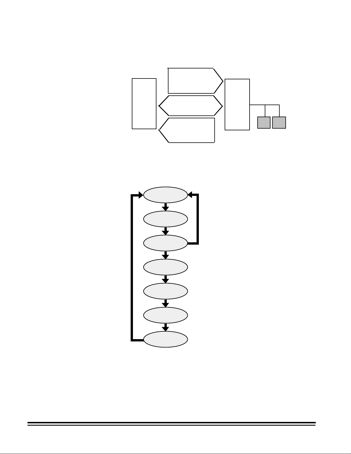
Setup
Follow this sequence to scan documents: set up the scanner,
enable scanning, initiate polling, feed documents, and disable
scanning.
To set up the scanner:
1. Determine and select the mode (configuration) to be used for
the current application.
The mode may be selected by the host computer using a
scanner-unique command (HA), or by the operator using the
scanner control panel.
2. Determine if any changes to the Image Processing parameters
need to be made for the current application. Execute the
required scanner-unique command(s) to make the desired
changes.
Image Processing parameter changes remain in effect until
one of the following conditions occur:
— The scanner is powered down using the main power
switch.
— A SCSI bus device Reset command is executed.
— A single parameter change is overridden by another
change to the same parameter.
3. Set the Sequential ID Number Seed and/or the Next Image
Address using a scanner-unique command (DC and HC,
respectively), if desired.
4. Calibrate the scanner. For procedures on how to do this, see
Kodak Digital Science
the
5. Prepare documents according to the instructions found in the
Kodak Digital Science
Scanner 9500, User’s Guide.
Scanner 9500, User’s Guide
.
A-61124 March 1999 2-1
Page 5

Enable scanning
The host must issue a SCSI Scan command (XX) to enable
scanning before documents can be transported through the
scanner. If scanning has not been enabled, the feeder and
transport system will not turn on.
Initiate polling
Feed documents
Disable scanning
Initiate host system polling of the scanner to ensure scanned
document images are transferred from the image buffer to the
host system. Polling should continue until scanning is disabled.
Feed documents according to the instructions found in the
Digital Science
Scanning is disabled to allow the host to download configuration/
setup changes between jobs and to handle certain types of
errors.
Scanning is disabled when one of the following conditions occur:
• The scanner is f irst powered on using the main power switch.
• A SCSI bus device Reset command is executed.
• An End-of-Job indicator is sent by the operator from the
scanner control panel.
• A scanner-unique End-of-Job command (GX) is issued by the
host computer.
• An error occurs requiring fault recovery.
Document Scanner 9500, User's Guide.
Kodak
Error handling
• The scanner portion of the machine has not been calibrated.
NOTE:Once scanning has been disabled, documents cannot be
scanned until the host enables scanning by issuing a
SCSI Scan command.
The scanner recognizes and reports a variety of error conditions .
Some errors are reported to either the host (via the SCSI
interface) or the scanner control panel, while others are reported
to both the host and the scanner control panel.
An error (via the SCSI interface) is defined as either a current
error or a deferred error.
A current error results from a problem in processing the current
SCSI command. This can include sending an invalid command,
trying to read from an empty image buffer, or an end-of-job
condition. Since one or more errors may be pending at any time,
current errors are reported first.
A deferred error results from an error condition within the
scanner, such as a document jam. Deferred errors that may have
occurred are reported after current errors.
2-2 A-61124 March 1999
Page 6

When an error occurs, the host will receive a SCSI Check
Condition Status. This indicates to the host that there may be
one current error and potentially one or more deferred errors.
The host must follow a Check Condition Status with a SCSI
Request Sense command. The Sense data will indicate the type
of error that has occurred.
To receive subsequent pending errors, the host must execute a
SCSI Test Unit Ready command. If a deferred error is pending,
the Test Unit Ready command will terminate with a Check
Condition Status. The host follows with a SCSI Request Sense
command. The combination of Request Sense followed by Test
Unit Ready must be repeated until a "good" status is returned on
the Test Unit Ready command. A "good" status indicates no
errors (current or deferred) are pending.
IMPORTANT:
If at any point the host receives a Check Condition
for a command and fails to issue a subsequent
Request Sense command, the scanner will clear
all (current and deferred) Sense data.
Some error conditions disable scanning and cause the document
transport to stop. These errors are reported on the scanner
control panel. This is done to prevent additional images from
entering the image buffer while allowing the host to perform fault
recovery activities. To aid in fault recovery, the information bytes
of the Request Sense data will contain a Sequential ID Number
for the approximate image upon which the error occurred.
NOTE:The scanner cannot determine exactly which images were
affected by the error and which images were not.
If an error occurs that disables the scanner, the host can continue
to read images from the image buffer without enabling the
scanner. However, when the image buffer has been emptied, an
error will be generated indicating fault recovery is required. This
differentiates between an end-of-job disable and a disable
caused by an error. The operator may continue scanning
documents after the host enables the scanner.
A-61124 March 1999 2-3
Page 7

Fault recovery
Fault recovery methods are required when unanticipated
circumstances interrupt scanning, such as a document jam. The
two methods described below meet the needs of most users.
However, other methods may be used.
Interactive/online method
IMPORTANT:
Before beginning fault recovery, make sure all the
images and headers have been transferred from
the image buffer to the host system.
Use the Interactive/online method when your primary concern is
that the database has no duplicate images.
Follow these steps to use the Interactive/online method:
1. At the host system, search through the most recently scanned
files to determine which images have been scanned and
transferred.
2. Find the last successfully scanned image. Record the
Sequential ID Number and/or the image address assigned to
the last successfully scanned image.
3. Sort through the stack of documents being scanned to find the
document that produced the last successfully scanned image.
You will have to rescan all of the documents that follow the last
successfully scanned document.
4. Download the Sequential ID Number and/or the Next Image
Address using a scanner-unique command (DC and HC,
respectively). The value(s) you download should correspond
to the document following the last successfully scanned image.
Batch/offline method
5. Begin scanning the documents that follow the last successfully
scanned document.
Use the Batch/offline method when your primary concern is
efficient use of time, duplicates in the database do not present a
problem, and there is adequate space in the database for the
duplicate images (same images with different Sequential ID
Numbers and image addresses).
Follow these steps to use the Batch/offline method:
1. Remove the stack of successfully scanned documents from
the exit hopper.
2. Take the last three or four documents from the top of the stack
and put them into the feed tray or at the top of the next stack
of documents.
3. Begin scanning the documents.
2-4 A-61124 March 1999
Page 8

3 Image Headers
Image header contents
This chapter provides an overview of the type of information
generated during the scanning process, and how to retrieve
images and headers.
The scanner collects the following information for each document
scanned:
Document number (Sequential ID Number)
The scanner assigns a unique Sequential ID Number to each
document. This number may be initialized by the host computer
using a scanner-unique command.
Image size
The scanner records the number of bytes required to store the
scanned document image.
Document level
The scanner assigns a document level to the scanned document
in one of the following ways:
• Press one of the Level Keys (I, II, III) on the control panel.
• Execute function code F94 (Level 1), F95 (Level 2), F96
(Level 3), or F07 (Level 0).
• Use the Footswitch accessory, if it is installed and enabled.
• Use a patch, if the Patch Reader accessory is installed and
enabled.
NOTE:If you do not use one of the methods above to assign a
document level, the level will be determined by the
mode defaults.
For example, assume the mode defaults assign a Level
2 to a document that follows a Level 3 document; and a
Level 1 to a document that follows a Level 2 document.
If the last document was assigned a Level 3, then the
current document is assigned a Level 2.
Mode
The scanner records the current operating mode that was
selected for the application.
Line length
The scanner records the number of pixels-per-line in an image.
Page length
The scanner records the number of lines-per-page in an image.
A-61124 March 1999 3-1
Page 9

Image address
The scanner assigns an image address to the scanned
document. The image address is based upon the index format
defined in the current operating mode and the document level
assigned to the document. Refer to Appendix C,
Image Addresses
for additional information.
Assigning
Header flags
The scanner records any flags that have been set for special
consideration. For example, a document image that may need to
go through a quality assurance check can be denoted by setting
a flag via the scanner control panel.
There are two types of flags:
• Latched flags. A latched flag is enabled and remains set until it
is disabled. In this case, the operator can execute function
code F73 and feed a set of documents. A flag is placed in the
header of all documents scanned until the operator executes
function code F73 to disable or reset the flag.
• Momentary flag. A momentary flag is set only for the next
document to be scanned. The operator can execute function
code F74 to momentarily set the flag and feed the document.
The flag is automatically reset for the next document.
Compression type
The scanner records the compression type used, which is
determined by either the mode definition or by the mode
definition override.
Date
The scanner records the date the document is scanned.
Time
The scanner records the time the document is scanned .
Resolution
The scanner records the selected scanned image resolution.
Bit order
The scanner records the selected bit order.
Skew Detection
If the Advanced Document Controller accessory is installed and
enabled, the scanner records whether or not a skew error was
detected.
Polarity
The scanner records the image polarity.
3-2 A-61124 March 1999
Page 10

Bar code header information
If the Bar Code Accessory is installed and enabled and a bar
code is detected on the document, the decoded information is
included in the image header.
Bar code information can contain a maximum of 106 ASCII
characters:
• 80 characters of actual data
• 9 delimiters
• a colon
• 14 bytes of image address information
• a line feed
• a null terminator
Samples:
<Bar Code>:<IA><line feed><null>
<Bar Code 1>;<Bar Code 2>;<Bar Code 3>:<IA><line
feed><null>
When using bar code, some situations may require evaluation of
Image Header data and, perhaps, manual cleanup of the
information contained in the header:
• During normal bar code reading, if a bar code is not decoded
properly (i.e., not recognized or only a portion of the code is
recognized), the bar code data will not appear in the image
header. For example, if there are two bar codes on a
document and only the second bar code is read and decoded
properly, only the data contained in the second bar code will
appear in the image header (making it appear as though only
one bar code was placed on the document).
• During partial bar code reading, if a bar code is not decoded
(i.e., not recognized or only a portion of the code is
recognized), a question mark may appear in the image
header. For example, if the start character followed by the
minimum number of characters is readable, the image header
will contain bar code information (corresponding to what has
been successfully read and decoded) followed by a semicolon (;) and a question mark (?).
• During reading of multiple bar codes, duplicate bar code
information may be placed in the header.
Image Deskew Flag
If the image was successfully skew corrected, this flag is set to 1
otherwise this flag is set to 0. This requires the Image Manager.
Skew Angle
The scanner will report the detected skew angle from 0 to 44
degrees independent of whether the image was skew corrected.
This requires the Image Manager.
A-61124 March 1999 3-3
Page 11

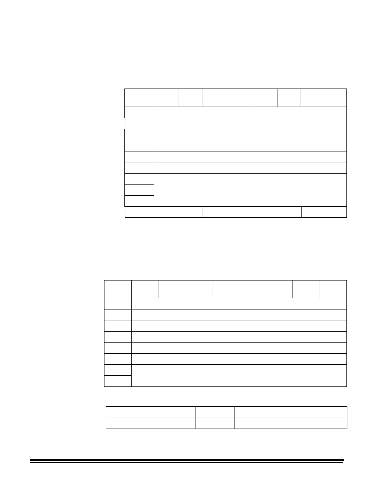
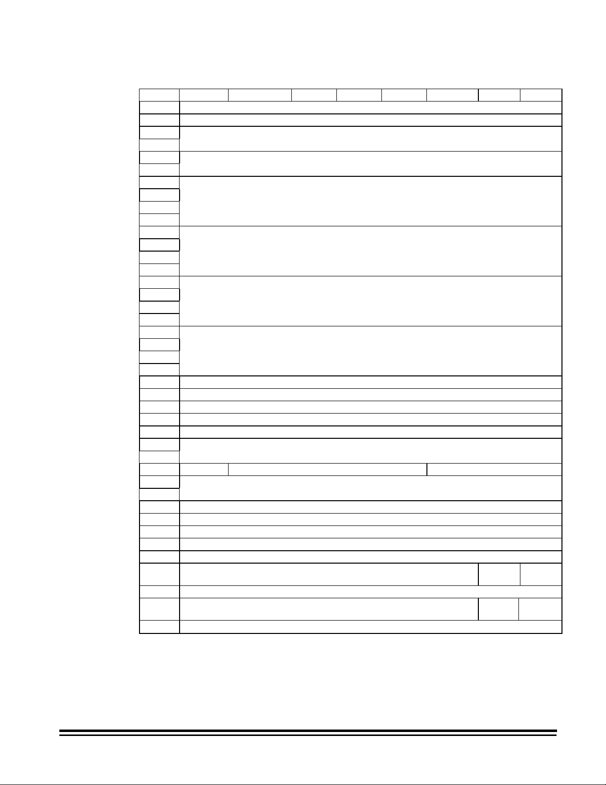
Image header format
The following table gives the position and the format of each
piece of data placed in the image header:
Set by
Offset Format Dynamic Data
7 ASCII-10 Sequential ID Number DC
27 ASCII-8 Image Size –
45 ASCII-2 Document Level –
54 ASCII-2 Mode HA
71 ASCII-8 Line Length –
95 ASCII-8 Page Length –
Command
110 ASCII-9
(Alpha)
120 ASCII-10 Image Address - Level 3
131 ASCII-10 Image Address - Level 2
142 ASCII-10 Image Address - Level 1
154 ASCII-2 Momentary Flag –
156 ASCII-2 Latched Flag –
165 ASCII-2 Compression Type FX/Y/Z
175 ASCII-2 Date - Month (1 to 12) –
177 ASCII-2 Date - Day (1 to 31) –
179 ASCII-2 Date - Year (00 to 99) –
189 ASCII-2 Time - Hours (0 to 23) –
191 ASCII-2 Time - Minutes (0 to 59) –
193 ASCII-2 Time - Seconds (0 to 59) –
220 ASCII-3 Resolution BX/Y/Z
Image Address - Fixed
Field
Field
Field
Field
–
–
–
–
227 ASCII-2 Bit Order EX
233 ASCII-4
242 ASCII-2 Polarity SX/Y/Z
256 ASCII-
106
368 ASCII-2 Image Deskew Flag† –
375 ASCII-2 Skew Angle† –
* 0 = No skew warning
1 = Skew warning (if Skew Detection accessory is installed)
† If the Image Manager is installed
3-4 A-61124 March 1999
Skew∗
Bar Code Data –
–
Page 12

NOTES:
• The header created for a rear side image is identical to the
header created for a front side image except for the literal value
(bytes 0–6); Front # is replaced by Rear #.
• Each piece of information collected during the scanning
process is placed in an image header associated with the
scanned document image (two-sided scanning produces two
image headers and two images-per-document; one-per-side).
• The image header consists of 512 bytes. The header format is
identical for all modes. The format is illustrated on the next
page.
A-61124 March 1999 3-5
Page 13
Default Image Header Format
01234567891011121314151617181920212223242526272829
Front # Lengt h =
30 31 32 33 34 35 36 37 38 39 40 41 42 43 44 45 46 47 48 49 50 51 52 53 54 55 56 57 58 59
Level = Mode = LFLin
60 61 62 63 64 65 66 67 68 69 70 71 72 73 74 75 76 77 78 79 80 81 82 83 84 85 86 87 88 89
e Lengt h = = Page Leng
90 91 92 93 94 95 96 97 98 99 100 101 102 103 104 105 106 107 108 109 110 111 112 113114 115 116 117 118 119
th = LfIA = =
120 121 122 123 124 125 126 127 128 129 130 131 132 133 134 135 136 137 138 139 140 141 142 143144 145 146 147 148 149
==
150 151 152 153 154 155 156 157 158 159 160 161 162 163 164 165 166 167 168 169 170 171 172 173174 175 176 177 178 179
Lf C m p = D a t e =
180 181 182 183 184 185 186 187 188 189 190 191 192 193 194 195 196 197 198 199 200 201 202 203204 205 206 207 208 209
Time - Roll # =
210 211 212 213 214 215 216 217 218 219 220 221 222 223 224 225 226 227 228 229 230 231 232 233234 235 236 237 238 239
Res= BO = SK= P0
240 241 242 243 244 245 246 247 248 249 250 251 252 253 254 255 256 361 362 363
I= Lf
364 365 366 367 368 369 370 371 372 373 374 375 376 377 378 379 380 … 511
Des= Ang=
nu nu nu nu nu nu nu nu nu nu nu nu
nu nu nu nu nu
Bar Code Data
nu
nu = Null (00H)
Lf = Line Feed (0AH)
Blank = Blank (20H)
NOTE:Resolution reported will be actual (rounded to the nearest
10 dpi).
3-6 A-61124 March 1999
Page 14

Retrieving images and headers
Headers and images are transferred to the host system via the
SCSI Read command. The data can be transferred in one of
three forms: header only, image only, or compound image, i.e.,
header with image. To determine the form, set the transfer type
within the SCSI Read command.
The image can be read in one of two ways:
• Read the header, then read the image.
• Read the compound image.
IMPORTANT:
The header should always be read before the
image. The header contains information
pertinent to the successful transfer of the image,
e.g., image size, and should be read prior to
reading the image.
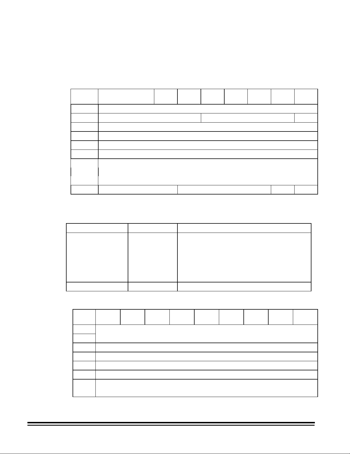
The following table illustrates the results of one Read command
followed by another. Assume that Image 1 is followed by Image
2.
Requested
Last Transfer
Compound (Header 1 and Image
1)
Compound (Header 1 and Image
1)
Compound (Header 1 and Image
1)
Header 1 Compound Header 2**
Header 1 Header Header 2**
Header 1 Image Image 1
Transfer
Compound Header 2
Header Header 2
Image Image 2*
Resultant
Transfer
Image 2
Image 2
Image 1 Compound Header 2
Image 2
Image 1 Header Header 2
Image 1 Image Image 2*
* Note that Header 2 was not transferred. This is not recommended.
** Note that Image 1 was not transferred.
3-8 A-61124 March 1999
Page 15

Recommended retrieval methods
The following examples illustrate how to retrieve image headers
and images.
To read compound images (image header with image) using
packets:
• Perform a SCSI Read asking for 64K bytes of compound data.
• From the header, you find the image is 316,000 bytes long.
Assuming the header is 512 bytes long, 65,024 bytes of image
were obtained from the first read. That means there are still
250,976 bytes of image to be read.
• Execute three more 64K-byte SCSI Read commands asking for
compound data to obtain a total of 261,632 (196,608 + 65,024)
bytes of image data.
• Execute a SCSI Read requesting 54,368 bytes of data.
To read the header and then read the image:
• Perform a SCSI Read asking for 512 bytes of header data.
• From the header, you find the image is 316,000 bytes long.
• Execute a SCSI Read asking for 316,000 bytes of image data.
A-61124 March 1999 3-9
Page 16

4 Scanner — Host Communications
This chapter provides an overview of the communication link
between the scanner and the host system. Communications
between the scanner and the host system occur across a SCSI
bus. The SCSI interface supports two-way command/data
communication between the scanner and the host system. The
SCSI-2 command set is supported.
Host to scanner communications
Scanner to host communications
SCSI data rates
The host transmits machine setup information to the scanner
using both the SCSI Define Windows command and the SCSI
Send command. The SCSI Define Windows command is used to
set up image processing parameters such as resolution,
threshold, contrast, etc.
The SCSI Send command transmits scanner-unique commands.
These allow settings of both image processing parameters and
machine configuration. These commands are embedded within
the Send command as data and can be identified by the 2-byte,
scanner-unique command field. A series of scanner-unique
commands may be sent as one data string within a single Send
command.
The scanner transmits digitized images to the host via the SCSI
interface using the SCSI Read command.
The scanner is capable of transmitting current image processing
setup information using the SCSI Get Windows command.
Additionally, the scanner can transmit both image processing and
configuration information using the SCSI Read command .
The
Digital Science
controller which is capable of faster SCSI transfer rates. It is
capable of operating at a sustained maximum data transfer rate
of 7 megabytes-per-second. Actual data transfer rate is a function
of the host system configuration.
Document Scanner 9500 has a SCSI
A-61124 March 1999 4-1
Page 17

5 The SCSI Interface
This chapter describes the SCSI interface used with the scanners.
For complete information on the appropriate SCSI specification,
refer to SCSI-2 Working Draft ANSI X. 131-198X, Revision 6,
10/29/88.
SCSI overview
SCSI bus
The SCSI interface provides a means of communication between
a maximum of eight computer and per ipher al devices, giving the
host computer independence within this system. As a result, tape
drives, printers, optical disks, com m unicat ions devices, et c. , can
be added to the host computer(s) without requiring modification to
the generic system hardware or software. The interface uses
"logical" rather than "physical" addressing for all data structures.
The SCSI bus allows communication between any two SCSI
devices at a time. W hen t wo SCSI devices communicat e on t he
bus, one acts as an initiator and the other act s as a t arget. The
initiator is usually a host computer that originates operations, and
the target is usually a peripheral controller that performs the
operation. A SCSI device generally has a fixed role as an initiator
or target, but some may assume either role. The scanner acts
only as a SCSI target.
Access to the SCSI bus is handled through bus arbitr ation. The
SCSI device with the highest priority (as determined by its SCSI
ID bit) is given control of the bus. The SCSI device with an ID of 7
is the highest priority device. The initiator t hen selects a target
and the target controls all further communications. Data tr ansfers
on the bus are asynchronous and follow a Request/Acknowledge
handshake protocol. One 8-bit byte of information is transferred
to the initiator with each handshake.
NOTE: The amount of time required to execute the SCSI
commands is affected by the number of peripheral devices
on the bus, as well as the priorities assigned to each
peripheral device. Therefore, t he amount of time required
to execute the SCSI commands will vary based upon the
system configuration. It is r ecommended that a dedicated
host adapter be used with the scanner.
A-61124 March 1999 5-1
Page 18
SCSI interface signal lines
The SCSI interface uses 18 sig nal lines:
Select (SEL)
Acknowledge (ACK)
Attention (ATN)
Reset (RST)
Issuing SCSI commands
Host
Computer
Initiator
Busy (BSY)
Data (DB(0)-DB(7))
Data Parity (DB(P))
Control/Data (C/D)
Input/Output (I/O)
Message (MSG)
Request (REQ)
Target
There are seven steps or phases for issuing com m ands t o t he
scanner or controller:
Bus Free
Arbitration
Selection
Command
Data
Status
Message
Bus Free phase — the SCSI bus is not being used by an initiator
(host computer) or the target (scanner). No signals on the bus
are asserted.
5-2 A-61124 March 1999
Page 19

Arbitration phase — an essential phase in a multi-host
environment with multiple initiators. In this phase, multiple
initiators compete for control of the bus. Only one initiator can
have control of the bus at a time. T he initiator asserts the BSY
signal, simultaneously this initiator out puts its own SCSI ID bit to
the SCSI bus. The initiator with the highest SCSI ID will win the
arbitration and assert the SEL (select ) signal. If the initiator does
not win the arbitration, it will revert to the Bus Free phase.
Selection phase — software connections are established
between an initiator and a target device. The init iat or selects the
target device by asserting the ID bit of the selected device and its
own ID bit. The initiator then de-assert s t he BSY signal, selecting
the target device.
Command phase — the initiator issues a command to the tar get
device. Commands are transmitted in a f ixed f or m at of 6, 8, or 10
consecutive bytes. Each command is distinguished by a unique
op code.
Data phase — data will be exchanged between the initiator and
the target device after t he specific commands are executed.
There are two types of data phases:
• Data-In, where the dat a is transmitted from the t ar get device
to the initiator, or
• Data-Out, where the data is transmitted from the initiator to
the target device.
Status phase — a status code is returned fr om the target to the
initiator indicating the status in which the comm and t erminated.
Occasionally, the system enters the Status phase f r om the
Command phase. Refer to the sect ion entitled, “SCSI status
responses” later in this chapter.
Message phase — messages will be exchanged between the
initiator and the target device. A m essage is transmitted from the
target device to the initiator, indicating the completion of a
command. Refer to the sect ion entitled, “SCSI message
responses” later in this chapter.
A-61124 March 1999 5-3
Page 20
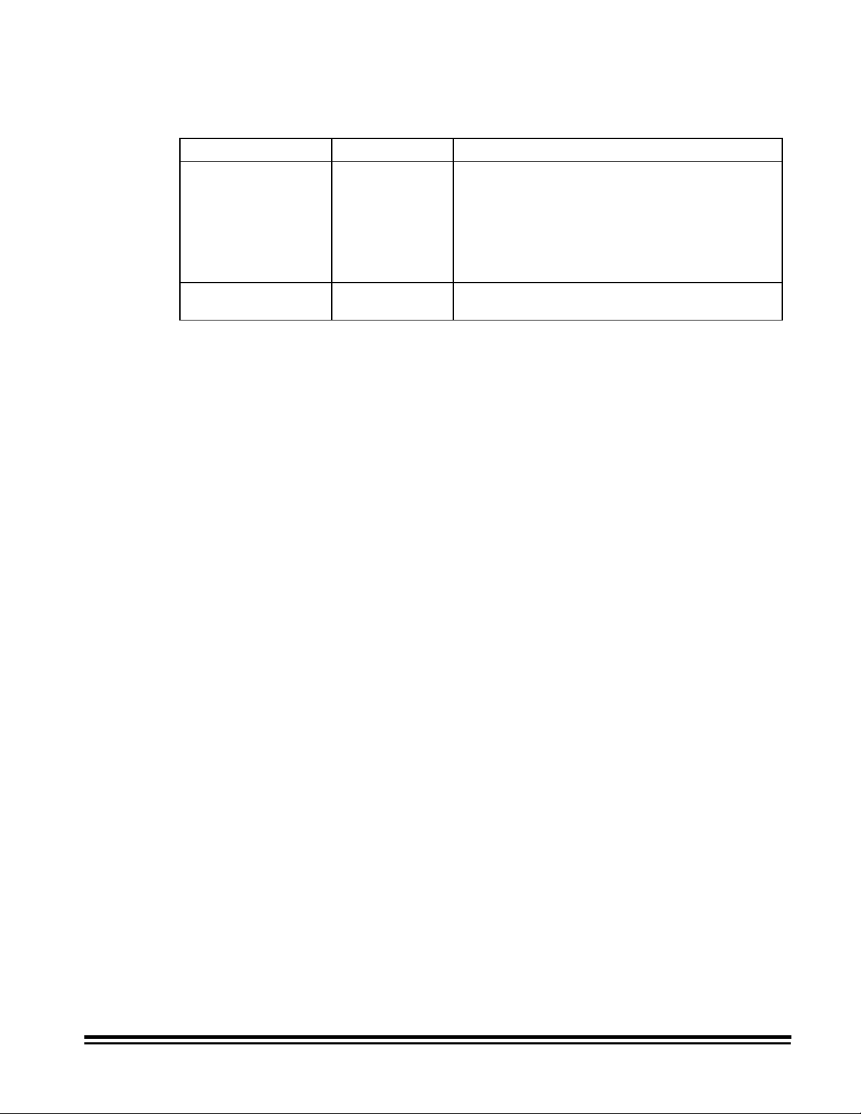
SCSI status responses
In the SCSI communication mode, a function is considered
incomplete until a valid status response is received from the other
end of the SCSI link. T here are three valid SCSI status
responses:
Status Response Code Meaning
Good Status 00H The frame was successfully
received and individual fields
within the frame contained legal
characters.
Check Condition
Status
Busy Status 08H Target is unable to accept
NOTE: "H" in the list above indicates hexadecimal notation.
02H A special condition occurred. A
SCSI Request Sense command
is required to obtain information
about the cause of the condition.
Some host adapters
automatically perform a Request
Sense command.
commands at the present time.
Host should try again. The host
should wait a minimum of 100
milliseconds before trying again.
5-4 A-61124 March 1999
Page 21

SCSI message responses
Message Code Directi on Function/Act i on SCSI Spec
Ref
Command
Complete
Initiator-Detected
Error
Abort 06H host- >scanner Scanner terminates current
Message Reject 07H host - >scanner Scanner cont inues current
Message Reject 07H scanner- > host Scanner rejected current
No Operation 08H host- >scanner Scanner continues current
Message Parity
Error
Bus Device
Reset
Identify 80H host- >scanner Scanner retains Logical
00H scanner- > host Scanner indicat ing the I/O
process is completed and a
valid status has been sent.
05H host- >scanner Scanner cont inues current
I/O process.
I/O process.
I/O process.
I/O process.
I/O process.
09H host- >scanner Scanner cont inues current
I/O process.
0CH host->scanner Scanner t er minates current
I/O process and performs a
hard reset.
Unit Number sent and
moves to the Command
phase.
Section 5.6.5
Section 5.6.11
Section 5.6.1
Section 5.6.15
Section 5.6.15
Section 5.6.17
Section 5.6.14
Section 5.6.3
Section 5.6.8
Extended
Message
NOTE: "H" in the list above indicates hexadecimal notation.
A-61124 March 1999 5-5
01H host- >scanner Scanner t r ansfers
remaining message bytes
and sends a Message
Reject. Synchronous Data
Transfers are not
supported.
Section 5.5
Page 22

SCSI conformance
The scanner conforms to t he SCSI specifications as follows:
• Single-ended, 8- bit bus, Cable A, shielded connector
(Alternative 2). Cable B is not supported.
• Single-initiat or (one host) is supported. Disconnect and
Reselect are not supported.
• Asynchronous maximum transfer rate of 1.2 M Bytes per
second.
• Linked comm ands and com m and queuing are not supported.
• Progr am m able target ID dip switch is factory set to 1.
• RST sig nal r eset is only monit ored. See the hard reset
alternative in SCSI Specifications (Section 5. 2.2.1).
• The scanner suppor t s Unit Attention condition following
power-up, SCSI bus device reset command or hard reset.
Refer to Section 6.13 of SCSI Specifications.
• The scanner operates as a target.
• The inter nal SCSI cable consumes 5 feet (1.5 meters) of the
maximum cable length allowed (19.7 feet/6 m eters).
• The scanner provides ter m inat ion power.
5-6 A-61124 March 1999
Page 23

SCSI commands
SCSI command summary
This section lists the SCSI commands that the scanner supports.
Information fo r each com m and includes:
• Command format operation codes (op codes).
• Section numbers t o reference in the SCSI-2 Specif icat ions.
• Command block descr iptor.
• Command specifics (parameters).
Command Op
Command Page Number
Code
Define W indow Paramet er s 5-8 24H
Get Window 5-12 25H
Inquiry 5-17 12H
Read 5-19 28H
Release Unit 5-20 17H
Request Sense 5-21 03H
Reserve Unit 5- 24 16H
Scan 5-24 1BH
Send 5-25 2AH
Test Unit Ready 5-27 00H
A-61124 March 1999 5-7
Page 24
Define Window Parameters command
Command op code: 24H
SCSI Specification: Section 14.2.1
Command block descriptor
Bit
Byte
0 Operation Code (24H)
1 Logical Unit Number Reserved
2 Reserved
3 Reserved
4 Reserved
5 Reserved
6 (MSB) Transfer Length
7
8 (LSB)
9 Vendor Unique Reserved Flag Link
Define Window Parameters header
76 5 43210
NOTE: For single-sided documents, a single Define Window
Parameters command should be sent. For t wo-sided
documents, two Define Window Parameters commands
should be sent; one containing inform at ion for the front
and one containing information for the rear.
Bit
Byte
0 Reserved
1 Reserved
2 Reserved
3 Reserved
4 Reserved
5 Reserved
6 (MSB) Window Descriptor Length
7 (LSB)
7654321 0
Define Window Parameters header data
Descriptor Data Definition
Window Descriptor Length = 46 Length of a single window descriptor.
5-8 A-61124 March 1999
Page 25
Define Window descriptor bytes
Bit Byte 7 6 5
0 Window Identifier
1
2 (MSB)
3
4 (MSB)
5
6 (MSB)
7 Upper Left X
8
9
10 (MSB)
11 Upper Left Y
12
13
14 (MSB)
15 Width
16
17
18 (MSB)
19 Length
20
21
22 Brightness
23 Threshold
24 Contrast
25 Image Composition
26 Bits Per Pixel
27 (MSB)
28
29 RIF Reserved Padding Type
30 (MSB)
31 (LSB)
32 Compression Type
33 Compression Argument
34... 39 Reserved
40 Image Enhancement Filter
41 Noise Filter
42 Reserved Allow 0 No
43 Reserved
44 Reserved Border
45 Reserved
43 21 0
Reserved
X Resolution
Y Resolution
Halftone Pattern
Bit Ordering
eduction
(LSB)
(LSB)
(LSB)
(LSB)
(LSB)
(LSB)
(LSB)
Scan
Deskew
A-61124 March 1999 5-9
Page 26

Define Window Parameters data
Descriptor Data Definition
Window Identifier = SFFFFF00 S=Side (0-Front, 1-Rear)
Auto = 0 Auto windows not supported
X Resolution = 0
= 70 to 300
Y Resolution = Defaults to X resolution
Upper Left X † = 0 to 14400* 0 to 12 inches (0 to 304.8 mm)
Upper Left Y † = 0 to 24000* 0 to 20 inches (0 to 508 mm)
Width † = 0,96 to 14400* 0 or 0.08 to 12 inches (2 to 304.8 mm)
Length † = 0,96 to 36000* 0 or 0.08 to 30 inches (2 to 762 mm)
Brightness = 0 Automatic brightness not supported
Threshold = 0, 1 to 255 When zero and "Allow Zero for Threshold &
Contrast = 0, 1 to 255 Percentage of adaptive threshold. When zero,
Image Composition = 00H, 01H 00H = Bi-level (default)
Bits per Pixel = 1 Only one bit available (8 bits internal)
Halftone Pattern = 0 to 7**
RIF = 0, 1 0 = zero white, one black
Padding Type = 00H Pad with 0s cannot be disabled
FFFFF=Mode (0-18)
If zero, will default to 200 dpi
Document Scanner 9500
Contrast" is zero, return to default value
and "Allow Zero for Threshold & Contrast" is zero,
return to default value
01H = Dithered (see halftone pattern)
ATP On:
0 = 2-level screen (no screen)
ATP Off:
1 = 16-level screen
2 = 32-level screen
3 = 64-level screen
4 = 3-level screen
5= 4-level Bayer dither
6= 16-level Bayer dither
7= 64-level Bayer dither
1 = zero black, one white (default)
* Measurement unit for scan region parameters is 1/1200 inch (0.0212 mm).
** Image Composition Halftone Pattern Result
00 any Halftone Pattern -> 0
00 0 No dithering (ATP or fixed threshold)
01 any Dither using specified halftone pattern
01 0 Image Composition -> 0
† If the Digital Science Image Manager is installed and enabled and all four parameters are 0, auto-
cropping is selected. If the Digital Science Image Manager is not installed and enabled, 0000 should not
be used.
5-10 A-61124 March 1999
Page 27

Descriptor Data Definition
Bit Ordering = 0000H
0001H
Compression Type = 00H, 01H,
02H, 03H
Compression
Argument
Image Enhancement
Filter
Noise Filter = 0, 1, 2 0 = no filter
Allow Zero for
Threshold & Contrast
No Scan = 0
Border Reduction = 0
Deskew = 0
= 000 - 255 K-parameter value for TSS Group III,
= 0, 2, 3
= 1
= 0
= 1
= 1
= 1
= 1
Always scans left to right, top to bottom
Data packing within a byte (bit ordering) is
selectable:
0000H=msb/right;lsb/left
0001H=msb/left;lsb/right (default)
00H = no compression
01H = TSS Group III, 1-dimensional
02H = TSS Group III, 2-dimensional
03H = TSS Group IV
2-Dimensional
0, 2, 3 = no filter (all pass)
1 = halftone removal
1 = remove lone pixels
2 = majority rule
When zero is entered for threshold or contrast,
use default.
When zero is entered for threshold or contrast,
use zero.
No scan off (scanning enabled)
No scan on (scanning disabled)
Border Reduction Disabled
Border Reduction Enabled
Skew Correction Disabled
Skew Correction Enabled
A-61124 March 1999 5-11
Page 28
Get Window command
Command op code: 25H
SCSI Specification: Section 14.2.2
Command block descriptor
Get Window data
Window Identifier = SFFFF00 S=Side (0-Front, 1-Rear) FFFFF=Mode (0-18)
Bit
Byte
0 Operation Code (25H)
1 Logical Unit Number Reserved Single
2 Reserved
3 Reserved
4 Reserved
5 Window Identifier
6 (MSB)
7 Transfer Length
8 (LSB)
9 Vendor Unique Reserved Flag Link
Descriptor Data Definition
Single = 0
7 654321 0
Window descriptors are returned for the current
mode with any temporary overrides and all 18
saved modes. For a duplex machine, 38 windows
are sent. For a simplex machine, 19 windows are
sent.
= 1
A single window descriptor will be returned as
specified by the window identifier.
Get Window Parameters header
Bit
Byte
0 (MSB) Window Data Length
1 (LSB)
2 Reserved
3 Reserved
4 Reserved
5 Reserved
6 (MSB) Window Descriptor Length
7 (LSB)
5-12 A-61124 March 1999
7654321 0
Page 29
Get Window Parameters header data
Descriptor Data Definition
Window Data Length = 54
882
1756
Window Descriptor
Length
= 46 Length of a single window descriptor
The value is equal to the data header, not including
the window data length (8 bytes) plus the number
of windows multiplied by the window descriptor
length
single window = 46 bytes
all windows/simplex = 874 bytes
all windows/duplex = 1748 bytes
A-61124 March 1999 5-13
Page 30
Get Window descriptor bytes
Bit/Byte7 6543210
0 Window Identifier
1 Reserved
2 (MSB) X Resolution
3 (LSB)
4 (MSB) Y Resolution
5 (LSB)
6 (MSB)
7 Upper Left X
8
9 (LSB)
10 (MSB)
11 Upper Left Y
12
13 (LSB)
14 (MSB)
15 Width
16
17 (LSB)
18 (MSB)
19 Length
20
21 (LSB)
22 Brightness
23 Threshold
24 Contrast
25 Image Composition
26 Bits Per Pixel
27 (MSB) Halftone Pattern
28 (LSB)
29 RIF Reserved Padding Type
30 (MSB) Bit Ordering
31 (LSB)
32 Compression Type
33 Compression Argument
34..39 Reserved
40 Image Enhancement Filter
41 Noise Filter
42 No Scan Allow 0 No Scan
43 Reserved
44 Reserved Border
45 Reserved
reduction
Deskew
5-14 A-61124 March 1999
Page 31

Get Window Parameters data
Descriptor Data Definition
Window Identifier = SFFFFF00 S=Side (0-Front, 1-Rear)
Auto = 0 Auto windows not supported
X Resolution = 70 to 300 Document Scanner 9500
Y Resolution =
Upper Left X † = 0 to 14400* 0 to 12 inches (0 to 304.8 mm)
Upper Left Y † = 0 to 24000* 0 to 20 inches (0 to 508 mm)
Width † = 0,96 to 14400* 0, 0.08 to 12 inches (2 to 304.8 mm)
Length † = 0,96 to 36000* 0, 0.08 to 30 inches (2 to 762 mm)
Brightness = 0 Automatic brightness not supported
Threshold = 0 to 255
Contrast = 0 to 255
Image Composition = 00H, 01H 00H = Bi-level (default)
Bits per Pixel = 1 Only one bit available (8 bits internal)
Halftone Pattern = 0 to 7**
RIF = 0, 1 0 = zero white, one black
Padding Type = 00H Pad with 0s cannot be disabled
Bit Ordering = 0000H
Compression Type = 00H, 01H,
Compression Argument = 000 - 255 K-parameter value for TSS Group III, 2-Dimensional
Image Enhancement
Filter
0001H
02H, 03H
= 0, 2, 3
= 1
FFFFF=Mode (0-18)
01H = Dithered (see halftone pattern)
ATP On:
0 = 2-level screen (no screen)
ATP Off:
1 = 16-level screen
2 = 32-level screen
3 = 64-level screen
4 = 3-level screen
5 = 4-level Bayer Dither
6 = 16-level Bayer Dither
7 = 64-level Bayer Dither
1 = zero black, one white (default)
Always scans left to right, top to bottom
Data packing within a byte (bit ordering) is selectable:
0000H=msb/right;lsb/left
0001H=msb/left;lsb/right (default)
00H = no compression
01H = TSS Group III, 1-Dimensional
02H = TSS Group III, 2-Dimensional
03H = TSS Group IV
0, 2, 3 = no filter (all pass)
1 = halftone removal
* Measurement unit for scan region parameters is 1/1200 inch (0.0212 mm).
** Halftone Pattern is automatically set to 0 if Image Composition is 0.
† If all four parameters are zero, auto-cropping is selected.
A-61124 March 1999 5-15
Page 32

Descriptor Data Definition
Noise Filter = 0, 1, 2 0 = no filter
1 = remove lone pixels
2 = majority rule
No Scan = 0
= 1
Border Reduction ‡ = 0
= 1
Skew Correction = 0
= 1
‡ Status indicated is the requested state. If auto-cropping is enabled, Border Reduction is ignored. See
the Y/X/Y/Z Command description.
No scan off (scanning enabled)
No scan on (scanning disabled)
Border Reduction disabled
Border Reduction enabled
Skew Correction enabled
Skew Correction disabled
5-16 A-61124 March 1999
Page 33

Inquiry command
Command op code: 12H
SCSI Specification: Section 7.2.5
Command block descriptor
EVPD = 0 Not supported
Page Code = 0 Not supported
Allocation Length = 0 - 56 If greater than 56 is specified, only 56 bytes will be returned
Inquiry descriptor bytes
Bit
Byte
0 Operation Code (12H)
1 Logical Unit Number Reserved EVPD
2 Page Code
3 Reserved
4 Allocation Length
5 Vendor Unique Reserved Flag Link
Bit
Byte
0 Peripheral Qualifier Peripheral Device Type
1 RMB Device-Type Qualifier
2 ISO Version ECMA Version ANSI-Approved Version
3 AENC Reserved Response Data Format
4 Additional Length
5 Reserved
6 Reserved
7 RelAdr WBus32 W Bus 1 6 Sync Linked Reserved Cmd
8... (MSB) Vendor Identification
...15 (LSB)
16... (MSB) Product Identification
31 (LSB)
32... (MSB) Product Revision Level
...35 (LSB)
36 Reserved (Front Side Accessories - 1)
37 Reserved (Front Side Accessories - 2) Image
38 Reserved (Rear Side Accessories - 1)
39 Reserved (Rear Side Accessories - 2) Image
40... Reserved (Vendor Specific)
...55
76543210
76543210
Soft
Reset
ATPFront
ATP-
Rear
Manager
Front
Manager
Rear
Queue
400 dpi
Front
400 dpi
Rear
A-61124 March 1999 5-17
Page 34

Inquiry data
Descriptor Data Definition
Peripheral Qualifier 000b
Peripheral Device 06H Scanner device
Remove Medium 0b Not removable
Device-Type Modifier 01H
02H
ISO Version 0 No compliance claims
ECMA Version 0 No compliance claims
ANSI Version 2H ANSI X3.131
Asynchronous Event
Notification
Capability
Response Data
Format
Additional Length 33H Additional bytes of inquiry data
Relative Addressing 0 Not supported
WBus32 0 32-bit wide transfers not supported
WBus16 0 16-bit wide transfers not supported
Sync 0 Synchronous transfers not supported
Linked 0 Linked commands not supported
CmdQue 0 Command queuing not supported
SftRes 0 RESET condition causes hard reset
Vendor Identification KODAKb/b/o/ Kodak
Product Identification DSb/ Scannerb/ 9500o/ Document Scanner 9500
Product Revision Current Version Current version
Adaptive Threshold
Processor Front
Adaptive Threshold
Processor Rear
400 dpi
Front
400 dpi
Rear
Image Manager
Functions — Front*
Image Manager
Functions — Rear*
b/ = blank
o/ = null
* Image Manager functions will both either be available or not available with duplex.
0 Set by initiators only
2H ANSI X3.131
0
1
0
1
0
1
0
1
0
1
0
1
Simplex (front only)
Duplex (front and rear)
Front ATP not available
Front ATP available
Rear ATP not available
Rear ATP available
400 dpi not available
Front 400 dpi available
400 dpi not available
Rear 400 dpi available
Front Image Manager Functions not
available
Front Image Manager Functions available
Rear Image Manager Functions not
available
Rear Image Manager Functions available
5-18 A-61124 March 1999
Page 35

Read command
Command op code: 28H
SCSI Specification: Section 14.2.5
Command block descriptor
Read data
Bit
Byte
0 Operation Code (28H)
1 Logical Unit Number Reserved RelAdr
2 Transfer Data Type
3 Reserved
4 (MSB) Transfer Identification
5 (LSB)
6 (MSB) Transfer Length
7
8 (LSB)
9 Vendor Unique Reserved Flag Link
76543210
Descriptor Data Definition
Logical Unit
= 0 Only one logical unit
Number
RelAdr = 0 Not supported
Transfer Type = 00
= 80
= 81
= 82
Transfer ID = 0
=
Scanner Unique
Image Data (raster data)
Scanner-unique command
Header
Compound Image (header, raster)
Not used when Transfer Type is 00, 81, or 82
When Transfer Type is 80, this field is used for
a scanner-unique command.
Command
Transfer Length
= length Maximum number of blocks (block size = 1
byte) to transfer.
NOTE: If Transfer Type = 80, use 128
*
If the quantity of data is less than the transfer length blocks,
Check Condition Status is returned. I ncor rect Length Indicator
(ILI) will be returned to the Req uest Sense that follows.
When performing continuous read commands, if a Check
Condition returns an indication the buffer is empty (sense key = B,
sense code = 80, and sense qualifier = 02), delay subsequent
read commands by at least 100 milliseconds.
*
For scanner-unique commands, a transfer length of 128 is recommended. The
command string is filled with nulls to a length of 128, ensuring the host
receives the data without generating a Check Condition for incorrect length.
A-61124 March 1999 5-19
Page 36

Release Unit command
Command op code: 17H
SCSI Specification: Section 14.2.6
Command block descriptor
This command is not fully implement ed. A Good Status will be returned if it is executed.
Bit
Byte
76543210
0 Operation Code (17H)
1 Logical Unit Number 3rdPty Third Party Device Reserved
2 Reserved
3 Reserved
4 Reserved
5 Vendor Unique Reserved Flag Link
5-20 A-61124 March 1999
Page 37

Request Sense command
Command op code: 03H
SCSI Specification: Section 7.2.15
Command block descriptor
Request Sense descriptor bytes
Bit
Byte
0 Valid Error Code
1 Segment Number
2
3 Information Bytes
4
5
6 (LSB)
7 Additional Sense Length
8 (MSB) Command-Specific Information
9
10
11 (LSB)
12 Additional Sense Code
13 Additional Sense Code Qualifier
14 FRU #
15 SKSV Sense Key Specific
16
17
Bit
Byte
0 Operation Code (03H)
1 Logical Unit Number Reserved
2 Reserved
3 Reserved
4 Allocation Length
5 Vendor Unique Reserved Flag Link
76543210
76543210
Filemark
EOM ILI
Reserved
Sense Key
A-61124 March 1999 5-21
Page 38

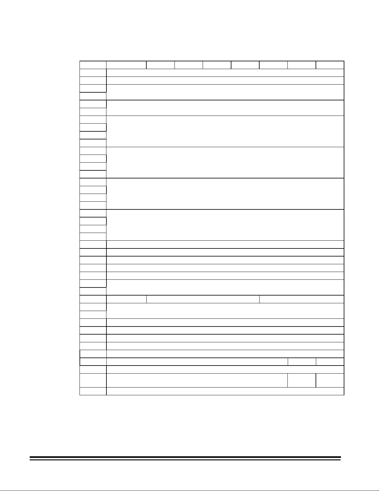
Request Sense data
Descriptor Data Definition
Valid = 1 Data is always valid
Error Code = 70H
Segment Number = 0 Not used
Filemark = 0 Not valid
EOM = 0 Not valid
ILI = 0
Sense Key = 00H
Information Bytes = residue
Additional Length = 10 Additional bytes of sense data (17–7)
Cmd Spec Info = 0 Not used
Additional Sense
Code, Qualifier
FRU# = Field Replaceable Unit
SKSV = Not used
Sense Key Specific = Not used
Current Error
= 71H
= 1
= 01H
= 02H
= 04H
= 05H
= 06H
= 0BH
= 0DH
= image #
= See “Request Sense data” section
Deferred Error
No Incorrect Length
Incorrect Length Indicator is on
No Sense or Incorrect Length
Recovered error
Not ready
Hardware error
Illegal request
Unit Attention
Aborted Command
Volume overflow (buffer overflow)
Difference between the requested bytes and the
actual bytes of data received (when ILI is on)
Sequential Image ID Number of approximate
image where Check Condition occurred
5-22 A-61124 March 1999
Page 39

Additional Info Scanner Disabled Error
Sense
Sense
Key
Code
0 00 00 No additional information
5 20 00 Invalid command operation code
5 20 80 Invalid scanner-unique command
5 20 82 Invalid scanner-unique command — unknown error
5 20 83 Invalid scanner-unique command — unknown command
5 20 84 Scanner-unique command executed at wrong time
5 20 85 Invalid scanner-unique command — bad data
5 20 86 Invalid scanner-unique command — wrong model
5 20 87 Invalid scanner-unique command — accessory not
5 20 88 Internal communications failure during scanner-unique
5 20 89 Internal processor failure during scanner-unique command
5 24 00 Invalid parameter in Command Data Block (CDB)
5 25 00 Unsupported Logical Unit
6 29 00 Power-on Reset
4 47 00 Parity Error on SCSI
4 4C 00 Logical Unit Failed Self-configuration — front
4 4C 00 Logical Unit Failed Self-configuration — rear
2 80 00 No data — End-of-Job condition Scanner disabled due to end key
2 80 01 No data — Fault recovery condition Scanner disabled due to previous error
B 80 02 No data - Buffer empty
D 81 00 Buffer Fault — Full
D 81 00 Buffer Fault — Front Compression Error
D 81 00 Buffer Fault — Rear Compression Error
D 81 01 Buffer Fault —- Document Queue Full
4 81 02 Front Image Lost (document record without page detect)
4 81 12 Rear Image Lost (document record without page detect)
4 81 03 Front Queue Error (document count out of sync)
4 81 13 Rear Queue Error (document count out of sync)
4 82 00 Machine Error —- Fault recovery required
4 83 00 Low Contrast Failure — black, front
4 83 10 Low Contrast Failure — black, rear
4 84 01 Calibration Failure — ARC, front * E713
1 84 02 Calibration Failure — dead pixels, front E294
1 84 03 Calibration Failure —- hot pixels, front E294
1 84 04 Calibration Failure — low lamps, front (scan camera) E110
1 84 04 Calibration Failure — low lamps, front (DSA) E208
4 84 05 Calibration Failure — target not seen, front
4 84 11 Calibration Failure — ARC, rear
1 84 12 Calibration Failure — dead pixels, rear E295
1 84 13 Calibration Failure — hot pixels, rear E295
1 84 14 Calibration Failure —- low lamps, rear (scan camera) E111
1 84 14 Calibration Failure — low lamps, rear (DSA) E209
4 84 15 Calibration failure — target not seen, rear
4 85 00 Board failure (AIP, PC, IM Checksum or IM Runtime)
4 85 00 Board failure (Front Buffer Parity Error) E718
4 85 00 Board failure (Rear Buffer Parity Error) E719
4 85 00 Board failure (SCSI Init Error)
Sense
Qualifier
Description
available
command processing
processing
Bytes
Seq. Id#
Recovery
Required
Fatal
Error
Calibration
Required
Stop
Trans
**
**
** *
** *
** *
** *
** *
** *
**
**
** *
** *
** *
*
*
*
**
**
Control
Panel
E721
E722
E701
E715
E716
E297
E702
E703
E705
E706
many
E292
E292
E296
E714
E296
E710
E709
A-61124 March 1999 5-23
Page 40

Reserve Unit command
Command op code: 16H
SCSI Specification: Section 14.2.6
Command block descriptor
This command is not fully implement ed. A Good Status will be returned if it is executed.
Bit
Byte
0 Operation Code (16H)
1 Logical Unit Number 3rdPty Third Party Device
2 Reserved
3 Reserved
4 Reserved
5 Vendor Unique Reserved Flag Link
Scan command
Command op code: 1BH
SCSI Specification: Section 14.2.7
Command block descriptor
Transfer length must be set to zero.
Bit
Byte
0 Operation Code (1BH)
1 Logical Unit Number Reserved
2 Reserved
3 Reserved
4 Transfer Length
5 Vendor Unique Reserved Flag Link
76543210
Reserved
76543210
5-24 A-61124 March 1999
Page 41

Send command
Send is required when executing scanner-unique commands.
Command op code: 2AH
SCSI Specification: Section 14.2.8
Command block descriptor
Send data
Bit
Byte
0 Operation Code (2AH)
1 Logical Unit Number Reserved RelAdr
2 Transfer Data Type
3 Reserved
4 Transfer Identification
5 (LSB)
6 (MSB) Transfer Length
7
8 (LSB)
9 Vendor Unique Reserved Flag Link
7 6543210
Descriptor Data Definition
Logical Unit Number = 0 Only one logical unit
RelAdr = 0 Not supported
Transfer Type* = 80 Scanner-unique command
Transfer ID = 0 Not used
Transfer Length* = length Maximum number of bytes to transfer
*The maximum number of bytes which can be transferred is 256.
A-61124 March 1999 5-25
Page 42

Using the Send
command for scannerunique commands
Scanner-unique commands may be sent to the scanner during the
Data Transfer phase of a SCSI Send command.
IMPORTANT: The Transfer Type field must be set to 80H.
The following tables illustrate how a scanner-uniq ue DA com m and
with a data field of 345.6 would be sent:
Command block
Byte
Number Description
0 Operation Code = Send 2AH
1 Logical Unit Number = 1 and Reserved = 0 20H
2 Transfer Type = Scanner-Unique
Command
3 Reserved = 0 00H
4 Transfer Identification (MSB) = not used 00H
5 Transfer Identification (LSB) = not used 00H
6 Transfer Length (MSB) = 0 00H
7 Transfer Length = 0 00H
8 Transfer Length (LSB) = 7 07H
9 Vendor Unique, Reserved, Flag, Link = 0 00H
Information sent during Data Transfer phase:
Byte
Number Description
0 Scanner-unique Data Field = 3 33H
1 Scanner-unique Data Field = 4 34H
2 Scanner-unique Data Field = 5 35H
3 Scanner-unique Data Field = . 2EH
4 Scanner-unique Data Field = 6 36H
5 Scanner-unique Command Field = D 44H
6 Scanner-unique Command Field = A 41H
7 Transfer Length (MSB) = 0 00H
Hexadecimal
Value
80H
Hexadecimal
Value
5-26 A-61124 March 1999
Page 43

Test Unit Ready command
Command op code: 00H
SCSI Specification: Section 7.2.17
Command block descriptor
Bit
Byte
0 Operation Code (00H)
1 Logical Unit Number Reserved
2 Reserved
3 Reserved
4 Reserved
5 Vendor Unique Reserved Flag Link
7 6543210
A-61124 March 1999 5-27
Page 44

6 Scanner-unique Commands
This chapter provides information about the scanner-unique
commands used for communication and data exchange between
the scanner and host system.
Scanner-unique commands, which are used to establish or
change the scanner configuration can be executed by sending a
SCSI Send command (with the Transfer Type set to 80H) from
the host system.
The host may query the scanner to determine the current scanner
configuration by executing a SCSI Read command with the
Transfer ID set to the 2-byte scanner-unique command. The
scanner will return the data field value and the scanner-unique
command as data for the Read command.
Scanner-unique command format
The scanner-unique command format is used to exchange
commands and data between the scanner and host. The scannerunique command format is described below.
Data Field Command Field
Data Field — contains numerical data (in ASCII format) and
ASCII character strings. It is variable in length.
Command Field — contains two bytes of upper-case alphabetic
ASCII characters that represent a unique scanner command. The
second command character received in a command sequence
indicates an End-of-Frame condition has been reached.
The following example shows how to create a scanner-unique
command:
This command transmits the numerical value 345.6 with scannerunique command DA.
HEX3334352E364441
CHAR 3 4 5 . 6 D A
NOTES:
• One or more of the scanner-unique commands may be sent
using the SCSI Send command.
• A command requiring a data field is not accepted by the
scanner without the data field.
• Do not add leading zeros to parameters unless instructed to do
so for a particular command.
• Limited auditing of the data fields is performed. Invalid data in a
data field may cause unexpected results.
A-61124 March 1999 6-1
Page 45

Command summary
Machine Level Commands May be used with:
Setup Bit Order EX Yes Yes 6–6
Control Clear Buffers CX Yes No 6–5
Mode Level Commands May be used with:
Scanner Configuration No Scan DX Yes Yes 6–6
Image Processing Commands
The following table provides a summary of all available scannerunique commands. Detailed descriptions of each command appear
on the pages indicated.
Description Command SCSI
Send
Count Only Mode MC Yes No 6–11
Sequential ID
Initiator
Define Mode JA Yes No 6–9
Set Mode HA Yes No 6–8
Last Image Address GC No Yes 6–7
Level of Next
Document
End of Job GX Yes No 6–8
Next Image
Address
Description Command SCSI
Simplex/Duplex
Status
Border Reduction YX/Y/Z Yes Yes 6–14
Compression FX/Y/Z Yes Yes 6–7
Cropping/AutoCropping
Dither Pattern
(Screen)
Image
Enhancement Filter
Noise Filter NX/Y/Z Yes Yes 6–12
Reverse Image SX/Y/Z Yes Yes 6–13
Scan Contrast KX/Y/Z Yes Yes 6–11
Scan Resolution BX/Y/Z Yes Yes 6–5
Scan Threshold JX/Y/Z Yes Yes 6–10
Skew Correction WX/Y/Z Yes Yes 6–14
DC Yes No 6–5
NF Yes No 6–12
HC Yes No 6–8
Send
TX Yes Yes 6–13
AX/Y/Z Yes Yes 6–4
LX/Y/Z Yes Yes 6–11
MX/Y/Z Yes Yes 6–12
SCSI
Read
SCSI
Read
Page
Page
NOTE: Image processing parameter defaults vary from mode to
mode. Refer to Appendix D, Im age Processing Parameter
Defauults to determine the default(s).
6-2 A-61124 March 1999
Page 46

There are three types of image processing commands:
• X commands affect both front and rear scanning.
• Y commands affect only front scanning.
• Z commands affect only rear scanning.
When using SCSI Send:
For duplex scanners, all three types of commands may be used.
For simplex scanners, only the Y command type may be used.
When using SCSI Read:
Use only the Y and Z command types.
A-61124 March 1999 6-3
Page 47

Commands
Each scanner-unique command is described in this section. The
command descriptions appear in alphabetical order.
AX/Y/Z Cropping/ Auto Cropping
The AX/Y/Z command defines the scan window (cropping
parameters) to be used for the current mode.
Data Field Command Field
xs3...xs0 xl3...x10 ys3...ys0 yl3...yl0 A X/Y/Z
Data Field Description Value(s)
xs3...xs0 Start location for left side of scanning
window — ASCII 4 bytes
xl3...xl0 Width of the scanning window —
ASCII 4 bytes
ys3...ys0 Top of the scanning window —
ASCII 4 bytes
yl3...yl0 Length of the scanning window —
ASCII 4 bytes
* This command accepts 3000 (30 inches). The maximum document
length is 30 inches with a compressed image file size less
2 Mbytes.
** If all data fields are 0000, auto-cropping is selected if the Digital
Science Image Manager is installed and enabled. If the Digital Science
Image Manager is not installed, 0000 should not be used.
0000–1200**
0000–1200**
0000–2000**
0000–3000*,**
NOTES:
• Leading zeros are required. All values entered should be
decimal values, to the nearest 0.01-inch (i.e., if the start location
3
is to be 2
⁄4 inches from the left margin, enter 0275). The
scanner automatically rounds each value entered to the nearest
0.08-inch (xs, xl and ys fields) or to the nearest 0.08-inch plus
one line for the yl field.
• The sum of xs and xl cannot exceed 1200.
• Document length checking (see the User’s Guide) is not
available for lengths greater than 20 inches.
6-4 A-61124 March 1999
Page 48

BX/Y/Z — Scan resolution
The BX/Y/Z command defines scanning resolution for the current
mode.
Data Field Command Field
res B X/Y/Z
Data Field Description Value(s)
res scan resolution in dots per inch 70 to 300*
* Values must be specified in increments of 10 dpi. If not, values will be
rounded to the nearest 10 dpi by the scanner.
NOTE: Leading zeros are not permitted.
CX — Clear buffers
DC — Sequential ID initiator
The CX command resets the image buffer and initializes the
Sequential ID Number to 1. This command is intended for use
only during integration testing and should not be used in a
production scanning application.
IMPORTANT: Executing the CX command may cause images in
the buffer to be lost. Similar ly, if the command is
executed while there are documents in the
transport, the new images may also be lost .
Data Field Command Field
none C X
The DC command is used to set the Sequential ID Number
(document count).
Data Field Command Field
cnt level D C
Data Field Description Value(s)
cnt image number value 0–999999999
level 9
The following example shows how the DC command could be
used:
The host application wants the starting image Sequential ID
Number (document count) to be 101.
The Sequential ID Initiator command must enter a value one less
than the desired starting value (to start with 101, the cnt value
must be 100).
HEX31303039 4443
CHAR 1 0 0 9 D C
A-61124 March 1999 6-5
Page 49

DX — No scan
The DX command enables or disables scanning for the current
mode.
Data Field Command Field
stat D X
Data Field Description Value(s)
stat no scan off (scanning enabled) 0
no scan on (scanning disabled) 1
EX — Bit order
The EX command defines the bit order within a byte of image
data.
Data Field Command Field
order E X
Data
Field Description Value(s)
order
• most significant bit (msb) to the right
• least significant bit (lsb) to the left
lsb msb
• most significant bit (msb) to the left
• least significant bit (lsb) to the right
msb lsb
0
1 (default)
6-6 A-61124 March 1999
Page 50

FX/Y/Z — Compression
The FX/Y/Z command defines the compression for the current
mode. It allows the optional specification of a K-factor for Group
III, two-dimensional compression.
Data Field Command Field
cmp K-factor (opt) F X/Y/Z
Data Field Description Value(s)
cmp uncompressed 0
Group III compression (one-dimensional) 1
Group III compression (two-dimensional) 2
Group IV compression 3
K-factor K-factor only has meaning when using
Group III, two-dimensional compression.
If Group III, two-dimensional is specified
without a K-factor, the K-factor will default
to 4.
000 (infinity)
to 255
NOTE: Leading zeros in the K-factor data field are required.
GC — Last image address
The GC command requests return of the last scanned document's
image address to the SCSI host.
Data Field Command Field
none G C
The information returned is in the following format:
Data Field Command Field
Image Address G C
Data Field Description Value(s)
Image
Address
Image address of the last scanned
document image
see NOTE
NOTE: The current application mode determines the image
address format.
A-61124 March 1999 6-7
Page 51

GX — End of job
The GX command initiates the scanner End of Job sequence.
This sequence includes:
• turning off the feeder
• flushing the transport
• turning off the transport
• disabling scanning
NOTE: The image buffer is not cleared.
Data Field Command Field
none G X
HA — Set mode
HC — Next image address
The HA command changes the current scanner configuration to
the configuration defined by the specified application mode.
Data Field Command Field
mode H A
Data Field Description Value(s)
mode mode number 1–18
NOTE: Only one Set Mode command may be sent with each SCSI
Send command.
The HC command sets the image address for the next document.
Data Field Command Field
STX image address ETX H C
Data
Field Description Value(s)
STX start of transmission indicator 02H
Image
Address
ETX end or transmission indicator 03H
the image address which is to be
assigned to the next document
see
NOTES
NOTES:
• The image address format must be compatible with the current
application mode. It must be sent to the scanner as if it were
entered on the scanner operator control panel. It should only be
sent when the scanner is idle.
• STX and ETX are optional when specifying numeric-only image
addresses. If the image address contains upper-case alphabetic
characters, STX and ETX must be used.
6-8 A-61124 March 1999
Page 52

JA — Define mode
The JA command alters the preprogrammed application mode by
storing the current operating mode in its place. After the current
operating mode has been stored as one of the 18 application
modes, it can be selected in one of two ways: the operator can
select it by entering function code F01 on the scanner operator
control panel; or the scanner-unique Set Mode (HA) command
may be used.
Data Field Command Field
mode J A
Data Field Description Value(s)
mode mode number 1–18
JA command Example 1:
• Mode 4 is the current application mode.
• The host executes the following FX command to disable
compression:
HEX 30 46 58
CHAR 0 F X
• The host executes a JA command, specifying Mode 4:
HEX 34 4A 41
CHAR 4 J A
When Mode 4 is selected from the scanner operator control panel,
all of the features of the mode that were available prior to the
execution of the FX command described above remain
unchanged, except compression (which is now disabled).
If the host had not executed the JA command following the FX
command, when the operator selects Mode 4 from the operator
control panel, ALL features of the mode that were available prior
to the execution of the FX command described above would
remain unchanged, including compression.
A-61124 March 1999 6-9
Page 53

JA command Example 2:
• Mode 4 is the current application mode.
• The host executes the following FX command to disable
compression:
HEX 30 46 58
CHAR 0 F X
• The host executes a JA command, specifying Mode 3:
HEX 33 4A 41
CHAR 3 J A
When Mode 3 is selected from the scanner operator control panel,
all of the features of Mode 4 that were available prior to the
execution of the FX command described above remain
unchanged, except compression (which is now disabled); these
values are assigned to Mode 3.
The Mode 3 definition has been overwritten by execution of this
command. When the operator selects Mode 4 again, all of the
features of Mode 4 that were available prior to the execution of
the FX command described above remain unchanged.
JX/Y/Z — Scan threshold
The JX/Y/Z command defines the threshold used for the current
mode.
Data Field Command Field
thresh J X/Y/Z
Data Field Description Value(s)
thresh scan threshold ranging from 0
(lightest) to 255 (darkest)
0 to 255
NOTE: Leading zeros are not permitted.
6-10 A-61124 March 1999
Page 54

KX/Y/Z — Scan contrast
The KX/Y/Z command defines the contrast used for the current
mode.
NOTE: A contrast of 0 results in a fixed threshold.
Data Field Command Field
cont K X/Y/Z
Data Field Description Value(s)
cont scan contrast ranging from 0 (fixed
thresholding) to 100 (fully adaptive)
0–100
NOTES:
• Leading zeros are not permitted.
• If multi-level screening is enabled (LX/Y/Z ≠ 0), this command is
used to enable/disable Error Diffusion.
LX/Y/Z — Dither pattern
(screen)
MC — Count Only mode
The LX/Y/Z command selects one of the eight screens for the
current mode.
Data Field Command Field
screen L X/Y/Z
Data Field Description Value(s)
screen 2-level screen (no screen)
16-level screen
32-level screen
64-level screen
3-level screen
4-level Bayer Dither
16-level Bayer Dither
64-level Bayer Dither
0
1
2
3
4
5
6
7
NOTE: Level is defined as the levels of gray simulated by the
screen.
The MC command enables or disables Count Only operation. The
image address does not change and no images are stored when
using Count Only mode.
Data Field Command Field
stat M C
Data Field Description Value(s)
stat disables Count Only mode 0
enables Count Only mode 1
A-61124 March 1999 6-11
Page 55

MX/Y/Z — Image enhancement filter
The MX/Y/Z command selects an Image Enhancement filter for
the current mode.
Data Field Command Field
filter M X/Y/Z
Data Field Description Value(s)
filter no filter (all pass) 0
halftone removal 1
no filter (all pass) 2
no filter (all pass) 3
NF — Level of next document
NX/Y/Z — Noise filter
The NF command sets the document image level for the next
scanned document.
Data Field Command Field
level N F
Data Field Description Value(s)
level sets Image Level of next document
to Level 0
sets Image Level of next document
to Level 1
sets Image Level of next document
to Level 2
sets Image Level of next document
to Level 3
0
1
2
3
The NX/Y/Z command selects the Noise filter for the
current mode.
Data Field Command Field
filter N X/Y/Z
Data Field Description Value(s)
filter noise filter disabled 0
remove lone pixels enabled 1
majority rule enabled 2
6-12 A-61124 March 1999
Page 56

SX/Y/Z — Reverse image
The SX/Y/Z command changes the white/black polarity for
the current mode.
Data Field Command Field
rev S X/Y/Z
Data Field Description Value(s)
rev white/0 black/1 0
white/1 black/0 1
TX — Simplex/duplex status
The TX command directs a duplex scanner to scan either
one or both sides of the document(s) for the current mode.
Data Field Command Field
side T X
Data Field Description Value(s)
side transmits only one side
(simplex/front only)
transmits two sides (duplex/front and
rear)
1
2
NOTE: Defaults to hardware configuration (simplex machine
defaults to single-sided; duplex machine defaults to
double-sided).
A-61124 March 1999 6-13
Page 57

YX/Y/Z — Border Reduction
If auto-cropping is off (see AX, Y, Z command), the Y
command removes borders on sides of documents.
Data Field Command Field
Border Y X/Y/Z
Data Field Description Value(s)
Border Border Reduction disabled 0
Border Reduction enabled 1
NOTE: If auto-cropping is on, and this command is sent, the
machine will store the last commanded state of the Y
command. This state becomes effective if auto-cropping is
turned off.
WX/Y/Z — Skew
Correction
The W command enables or disables document skew correction.
Data Field Command Field
Skew Correction W X/Y/Z
Data Field Description Value(s)
Skew
correction
Skew correction enabled 1
Skew correction disabled 0
6-14 A-61124 March 1999
Page 58

Scanner-unique command samples
There are several ways to alter the default image processing
parameters:
• temporarily override an individual parameter
• temporarily override a group of parameters
• permanently change an individual parameter
• permanently change a group of parameters
Temporary individual parameter overrides are performed by
sending a single scanner-unique command using a single SCSI
Send command. The temporary parameter change remains in
effect until one of the following occurs:
• a new value for the same parameter is sent
• the parameter value(s) are saved to a mode
• change to another mode
• a SCSI or power-on reset occurs
The following table illustrates how the use of a single scannerunique command can temporarily override a current mode
parameter:
RESULT
ACTION Compression Resolution
Scanner is in Mode 1 3* 200*
Host executes SCSI Send
command with 2FX
Host executes SCSI Send
command with 4HA
Host executes SCSI Send
command with 1HA
2 200*
3* 200*
3* 200*
*Parameter default value.
Temporarily overriding a group of parameters
Temporary group parameter overrides are performed by sending
a string of scanner-unique commands using a single SCSI Send
command. The temporary parameter changes remain in effect
until one of the following occurs:
• an individual parameter value is sent (changing only that
parameter value)
• the parameter value(s) is saved to a mode, or you change to
another mode
• a SCSI or power-on reset occurs
A-61124 March 1999 6-15
Page 59

The following table illustrates how the use of a string of scannerunique commands can temporarily override current mode
parameters:
RESULT
ACTION Compression Resolution
Scanner is in Mode 1 3* 200*
Host executes SCSI Send command
with 2FX300BX
Host executes SCSI Send command
with 4HA
Host executes SCSI Send command
with 1HA
2 300
3* 200*
3* 200*
*Parameter default value.
Permanently changing individual parameters
A permanent change to an individual parameter is performed by
temporarily overriding a single parameter and then sending a
scanner-unique Define Mode (JA) command to save the values to
a specified mode.**
The following table illustrates how the use of a scanner-unique JA
command can be used to permanently change a current mode
parameter:
RESULT
ACTION Compression Resolution
Scanner is in Mode 1 3* 200*
Host executes SCSI Send command
with 2FX
Host executes SCSI Send command
with 4JA
Host executes SCSI Send command
with 4HA
Host executes SCSI Send command
with 1HA
2 200*
2 300
3* 200*
* Parameter default value.
** The value(s) may be saved to the current mode or any of the
other modes.
6-16 A-61124 March 1999
Page 60

Permanently changing a group of parameters
A permanent change to a group of parameters is performed by
temporarily overriding a group of parameters and then sending a
scanner-unique Define Mode (JA) command to save the values to
a specified mode.**
The permanent parameter changes remain in effect until a SCSI
or power-on reset occurs.
The following table illustrates how the use of a scanner-unique JA
command can be used to permanently change a group of current
mode parameters:
RESULT
ACTION Compression Resolution
Scanner is in Mode 1 3* 200*
Host executes SCSI Send command
with 2FX300BX
Host executes SCSI Send command
with 4JA
Host executed SCSI Send command
with 4HA
Host executes SCSI Send command
with 1HA
Scanner is in Mode 1 3* 200*
Host executes SCSI Send command
with 2FX300BX4JA
Host executed SCSI Send command
with 4HA
Host executes SCSI Send command
with 1HA
2 300
2 300
3* 200*
2 300
2 300
3* 200*
* Parameter default value.
** The value(s) may be saved to the current mode or any of the
other modes.
A-61124 March 1999 6-17
Page 61

Recommended usage of scanner-unique commands
The recommended method of downloading and saving image
processing parameters, when using scanner-unique commands,
is to use a SCSI Send command to transmit all desired parameter
changes, and a Define Mode (JA) command to permanently store
the parameter changes in a specified mode. This method
significantly reduces SCSI overhead.
For example:
Using one SCSI Send command:
250BX1FX180JX60KX5LX1NX2TX1JA
will:
• set the scan resolution to 250 dpi
• set the compression to Group III, one dimensional
• set the threshold to 180
• set the scan contrast to 60
• set the dither pattern to a 4-level Bayer dither
• set the noise filter to remove noise reduction
• set the simplex/duplex status to two-sided
• save the parameter values in Mode 1
6-18 A-61124 March 1999
Page 62

7 The Diagnostic Interface (J45/COIN3)
This chapter describes the communications between the scanner
and an RS-232 terminal, which may used to receive diagnostic
information.
Usage
Protocol
Pinouts
The diagnostic interface ( also r eferred to as COIN3) may be used
to receive diagnostic messages. This interface may be used as a
diagnostic tool during product development and int egration.
The diagnostic port is labeled J45 on the rear panel of the
scanner.
The RS-232 communications protocol is:
• 9600 baud without the Image Manager accessory
19,200 baud with the Image Manager accessory
• 8 bits
• 1 start/stop bit
• No parity
• No handshake on DTR/CT S
A standard RS-232 interface is used
The diagnostic port (J45) has the following pinouts (25-pin female
DB 25 Connector):
Pin (J45) Signal(s)
2T x D
3R x D
5CTS
7GND
20 DTR
Sample interfaces
FROM TO FROM TO
Scanner PC serial port Scanner PC serial port
(25-pin male) (9-pin female) (25-pin male) (25-pin female)
8 _____________ 1 1 ______________ 1
2 _____________ 2 3 ______________ 2
3 _____________ 3 2 ______________ 3
6 _____________ 4 5 ______________ 4
7 _____________ 5 3 ______________ 5
20 _____________ 6 20 _____________ 6
5 _____________ 7 7 ______________ 7
4 _____________ 8 6 ______________ 20
22 _____________ 9
A-61124 March 1999 7-1
This section illustrates the connection between the scanner
diagnostic port (J45) and the serial port of a personal computer.
Page 63

Appendix A Glossary
Batch
A number of documents to be scanned as a group.
Bi-tonal image
An unscreened image that consists of pixels which are either
black or white (1 bit/pixel), as opposed to gray scale (screened)
images which consist of pixels which are assigned a value based
upon a range of gray shades.
Calibration
An operation that determines any system nonuniformity for which
the scanner must compensate during scanning. The unit must be
calibrated at least once a day or after power has been turned on.
Charge-coupled device (CCD)
A light-sensitive, solid-state device used to convert image
information (light) to electrical signals as a document is scanned.
Compression
Compression is used to reduce the number of bytes needed for
scanned document images, thus saving storage space and/or
transmission time. This is accomplished with special algorithms
that use run-length encoding.
Continuous tone images
Images, such as photographs, which can assume all possible
shades of gray.
Cropping
Technique used to capture a desired portion of an image. Allows
the entire document to be scanned without all document data
being stored.
Digitized image
Image data represented by binary ones and zeros.
A-61124 March 1999 A-1
Page 64

Document image level
Rank associated with a type of document. Up to four levels —
Level 3, Level 2, Level 1, and Level 0 — can be used. The level
can be set automatically using a Patch Reader accessory,
manually by pressing the Footswitch, by pressing a Level key on
the control panel, or by sending a scanner-unique Level of Next
Document command.
Error diffusion mode
Compromised between binary thresholding and screening; used
for documents containing both continuous tone photographic and
text information. It simulates gray scale while retaining text
readability.
Gray scale image
Refers to a processed image that consists of pixels which are
assigned values based upon a range of gray shades, as opposed
to thresholded images in which each pixel is either black or white.
Gray levels
Discrete shades of gray.
Halftone image
Refers to a printed image that simulates a continuous tone
image. The simulation is achieved by using a series of dot
patterns. Newsprint pictures are an example of halftoned images.
Header
Contains information associated with the raster image file.
Consists of fixed fields (provided by the host computer) and
scanner-determined dynamic fields (image sequence number,
image size in bytes, image level).
Image address
Contains fixed and dynamic information which can be used for
image retrieval.
Initiator
A SCSI device (usually a host) that requests an operation to be
performed by another SCSI device.
A-2 A-61124 March 1999
Page 65

Multilevel indexing
A method of organizing documents in a structured manner when
one type of document is associated with a particular level and
another type of document is associated with another level of
greater or lesser importance. For example, an insurance
application with batches associated with Level 3, claims
associated with Level 2, and claim attachments associated with
Level 1.
Noise
Small dots or specks that appear in the background of an image.
These specks increase file compression size and usually contain
no image information.
Noise filter
Reduces random noise on bi-tonal images by converting a black
pixel surrounded by white pixels to white, or a white pixel
surrounded by black pixels to black.
Patch
A coded grouping of wide and narrow bars that are preprinted on
documents. Patches are read by an optional Patch Reader and
signal a level change for that document or the next document.
Multilevel indexing
See
.
Pixel
A picture element. A binary or multi-bit value which represents a
spot on a target document. The more pixels, the higher the
resolution.
Point
The basic unit of type measurement which determines the
character height. 1 point = 1/72 of an inch.
Point SizeFont
4
6
7
9
10
12
Kodak Digital Science
Kodak Digital Science
Kodak Digital Science
Kodak Digital Science
Kodak Digital Science
™ Document Scanner Products
™ Document Scanner Products
™ Document Scanner Products
™ Document Scanner Products
™ Document Scanner Products
Kodak Digital Science
™ Document Scanner
Products
A-61124 March 1999 A-3
Page 66

Scaling
Method used to obtain output resolutions other than the base
resolution of the scanner. Can be done only from a higher
resolution to a lower resolution.
Scanner-unique command
Allows the host computer and the scanner to communicate with
each other. Scanner-unique commands must be in the format
described in this manual.
Screening
Creates a pseudo gray-scale image and the electronic equivalent
of the technique newspapers use to print pictures.
Recommended for continuous tone photographic images. Also
referred to as an 'ordered dither.’
Seed
A Sequential ID Number, sent from the host to the scanner, which
will be used as the first number for the document image number.
Small computer-system interface (SCSI)
Evolving industry ANSI standard that facilitates communication
between computers and their (SCSI) intelligent peripherals. The
scanner transmits digitized image data to the appropriate host
subsystem via the SCSI bus. The interface supports two-way
command/data communication between the scanner and the
host. The SCSI-2 command set is supported as well as a set of
scanner-unique commands.
Thresholding
The conversion of a gray scale image into a bi-tonal (1 bit/pixel)
image. Thresholding techniques include fixed, adaptive, screen
and mixed.
A-4 A-61124 March 1999
Page 67

Appendix B Reference Materials
Ordering publications
The following publications are available for the
Science
A-61092 User's Guide
A-61124 Integrator's Guide
A-61094 Installation Planning and System Maintenance Guide
A-61097 Installation Questionnaire Instructions/Mode Setup
Accessory-specific
A-61099 Bar Code Made Easy
A-61599 Patch Code Information for
United States and Canada
Provide the quantity, publication name and number, name and
phone number of caller, purchase order number, billing address
and ship-to address.
• Place telephone requests (toll-free) between 8: 00 AM and
8:00 PM (EST) Monday through Friday: 1 (888) 247-1234.
Document Scanner 9500.
Software
Kodak Digital Science
Products
Kodak Digital
• Facsimile requests should be sent: 1 (800) 535-4622
All other regions
Parts, tools, and publications are available through local
channels.
A-61124 March 1999 B-1
Page 68

Appendix C Assigning Image Addresses
An image address may contain up to 15 characters, consisting of
a maximum of 12 digits and a maximum of 3 delimiters.
You must define the following four fields:
• Field A represents Level 1. Its value is incremented when a
document is assigned Level 1.
• Field B represents Level 2. Its value is incremented when a
document is assigned Level 2. In addition, the value of Field
A is reset to zero.
• Field C represents Level 3. Its value is incremented when a
document is assigned Level 3.
• Fixed Field contains fixed information, typically, the date.
Example: 0301.02.001.000 where:
Field A contains 000
Field B contains 001
Field C contains 02
Fixed Field contains 0301
The image address field lengths depend upon the Index Format
you select:
• Single Level Format
Field A is defined as having a field length greater than zero.
Field B is defined as having a field length of zero.
Field C is defined as having a field length of zero.
Fixed Field may be defined, if desired.
Example: FFFFFF.AAAAAA
• Two Level Offset Format
Field A is defined as having a field length of zero
Field B is defined as having a field length greater than zero.
Field C is defined as having a field length of zero.
Fixed Field may be defined, if desired.
Example: FFFFFF.BBBBBB
• Two Level Format
Field A is defined as having a field length greater than zero.
Field B is defined as having a field length greater than zero.
Field C is defined as having a field length of zero.
Fixed Field may be defined, if desired.
Example: FFFFFF.BBB.AAA
A-61124 March 1999 C-1
Page 69

• Three Level Offset Format
Field A is defined as having a field length of zero.
Field B is defined as having a field length greater than zero.
Field C is defined as having a field length greater than zero.
Fixed Field may be defined, if desired.
Example: FFFFFF.CCC.BBB.
• Three Level Format
Field A is defined as having a field length greater than zero.
Field B is defined as having a field length greater than zero.
Field C is defined as having a field length greater than zero.
Fixed Field may be defined, if desired.
Example: FFFF.CC.BBB.AAA
C-2 A-61124 March 1999
Page 70

Appendix D Image Processing Parameter Defaults
Image processing parameters
Image processing parameters are fine-tuned during integration
for each application/document type, with the goal of optimizing
document image quality.
At the beginning of the optimization process, the default image
processing parameter settings should be used as a base when
fine-tuning the image processing parameters:
• Set each of the image processing parameters to the
recommended settings for your application/document type (not
necessary if the default settings are used).
• Scan several samples of the application documents.
• Evaluate the document images.
If the quality of the document image is not satisfactory, change
one or more of the parameter settings slightly and scan the
sample application documents again. Continue this process until
the desired image quality is obtained.
In addition to the default and recommended image processing
parameter settings, sample image processing parameters are
provided in
processing parameter settings may be used as guidelines when
establishing the desired image processing parameter settings if
your application/document type is similar to the sample images.
Appendix E, Image Processing
. The sample image
A-61124 March 1999 D-1
Page 71

Table D-1 — Scanner 9500 with the Image Manager
Default image processing parameters
Parameter Command
Scan (X & Y)
BX/Y/Z 200 200 200 200 200 300 300
Resolution
Cropping
AX/Y/Z auto crop auto crop auto crop auto crop
Parameters
x start =
x length =
y start =
y length =
Threshold
Contrast
Screen (Dither
JX/Y/Z 90 90 90 90 90 90 90
KX/Y/Z 62 62 62 62 62 62 62
LX/Y/Z 0 (2-level) 0 (2-level) 0 (2-level) 0 (2-level) 2 (32-level) 3 (64-level) 0 (2-level)
Pattern)
Enhancement Filter
Compression Type
Noise Filter
Reverse Image
Skew Correction
Border Reduction
MX/Y/Z 0 (no filter) 0 (no filter) 1 (halftone
FX/Y/Z Group IV Group IV Group IV Group IV Group IV Group IV Group IV
NX/Y/Z 0 (no filter) 0 (no filter) 1 (noise
SX/Y/Z 0 (white/0) 0 (white/0) 0 (white/0) 0 (white/0) 0 (white/0) 0 (white/0) 0 (white/0)
WX/Y/Z 1 (on) 0 (off) 1 (on) 0 (off) 1 (on) 0 (off) 1 (on)
YX/Y/Z 0 (off) 0 (off) 0 (off) 0 (off) 0 (off) 0 (off) 0 (off)
Modes
1,5,9,
0 170 0 170 0 170 0
0 864 0 864 0 864 0
00000 0 0
0 1104 0 1104 0 1104 0
Modes
13,17
Modes
2,6,10
removal)
reduction)
Modes
14,18
1 (halftone
removal)
1 (noise
reduction)
Modes
3,7,11,15
0 (no filter) 0 (no filter) 0 (no filter)
0 (no filter) 0 (no filter) 0 (no filter)
Modes
4,8
Modes
12,16
D-2 A-61124 March 1999
Page 72

Recommended Image processing parameters
Document Type Threshold
(JX/Y/Z)
Table D-2 — Scanner 9500
Image
Contrast
(KX/Y/Z)
Screen
(LX/Y/Z)
Enhancement
Filter
Noise Filter
(NX/Y/Z)
Compression
All Text Documents
(ATP enabled)
Continuous tone*
(photographic)
(standard IP enabled)
Pictorial Halftones*
(standard IP enabled)
Continuous tone*
photographic) with text
(7-point type or larger)
(standard IP enabled)
90 (default) 62
(default)
100-120
<100, >1200Not used
100-120
<100, >1200Not used
100-120
(Error
Diffusion)
>0
(Error
Diffusion)
2-level None On On
Any–MultiLevel
2-level Halftone
Any–MultiLevel
Any Off Off
Off Off
Removal
None Off Off
* ATP is standard in the Scanner 9500. Howev er, standard image processing modes are reserved for
continuous tone or halftone documents by selecting any multi-level screen as shown above.
A-61124 March 1999 D-3
Page 73

Table D-3 — Scanner 9500 without the Image Manager
Default image processing parameters
Parameter Command
Scan (X & Y)
BX/Y/Z 200 200 200 300
Resolution
Cropping
AX/Y/Z
Parameters
x start =
x length =
y start =
y length =
Threshold
Contrast
Screen (Dither
JX/Y/Z 90 90 90 90
KX/Y/Z 62 62 62 62
LX/Y/Z 0 (2-level) 0 (2-level) 2 (32-level) 3 (64-level)
Pattern)
Enhancement Filter
Compression Type
Noise Filter
Reverse Image
MX/Y/Z 0 (none) 0 (none) 0 (none) 0 (none)
FX/Y/Z Group IV Group IV Group IV Group IV
NX/Y/Z 0 (no filter) 1 (lone pixels) 0 (no filter) 0 (no filter)
SX/Y/Z 0 (white/0) 0 (white/0) 0 (white/0) 0 (white/0)
Modes
1,5,9,13,17
170 170 170 170
864 864 864 864
0000
1104 1104 1104 1104
Modes
2,6,10,14,18
Modes
3,7,11,15
Modes
4,8,12,16
NOTE: The following commands are not available without the Image Manager:
• WX/Y/Z Skew Correction
• YX/Y/Z Border Reduction
• AX/Y/Z The special case of the Cropping command to enable/disable auto-cropping
is not available.
D-4 A-61124 March 1999
Page 74

Appendix E Image Processing
This appendix provides an overview of image processing
capabilities which are controlled by the host computer using
scanner-unique commands and guidelines for evaluating scanned
images.
This information pertains to the following:
Terminology
Kodak Digital Science
•
Kodak Digital Science
•
Kodak Digital Science
•
NOTE: For the purpose of this appendix, when referring to the
scanner and the scanner/microimager the term “
will be used. Any specific differences between the
Document Scanner 9500, 5500, 7500 series and the
Scanner/Microimager 990 will be noted.
The following terms are used when describing the image
processing capabilities of the scanner.
AdaptiveThreshold Processing — separates the foreground
information in an image from the background information.
Bi-tonal image — an unscreened image that consists of pixels
which are either black or white (1 bit/pixel).
Continuous tone image — an image, such as a photograph,
which can assume all possible shades of gray.
Digitized image — an image made up of pixels represented by
binary ones and zeros.
Scanner 9500 series
Scanner 5500 and 7500 series
Document Scanner/Microimager 990
scanner
”
Gray levels — discrete shades of gray.
Gray scale images — an image that consists of pixels which are
assigned values based upon a range of gray shades.
Halftone images — the simulation of a continuous tone image by
a printing process. The simulation is achieved by using a series
of dot patterns. Newspaper photographs are an example of
halftone images.
Noise (background noise) — small dots or specks that appear
in the background of a scanned image. These specks increase
file compression size and usually contain no image information.
Pixel — a single picture element of a digitized image. Pixels can
be binary (1 bit/pixel) or gray (multiple bits).
A-61122/A-61124 March 1999 E-1
Page 75

Image p rocessing capabilities
This section describes the standard capabilities of the scanner.
Refer to the end of this section for information on how to use the
AdaptiveThreshold Processor accessory.
Cropping
Auto-cropping
Cropping is a method of capturing a portion of the total document
being scanned. The host computer provides the scanner with the
following information that defines which por tion of the document
is to be captured:
• Left margin — the left-most point is 6 inches (152.4 mm) from
the feeder/transport centerline. The left margin is defined as the
distance from this point.
• Width — the distance from the left margin.
• Top margin — the distance from the leading edge of the
document.
• Length — the distance from the top margin.
Refer to Chapter 6
of the AX/Y/Z command.
, Scanner-unique Commands
for a description
This option is only available for Document Scanners with the
Kodak DigitalScience
Image Manager accessory installed (not
the Scanner/Microimager 990).
The Image Manager provides border detection for use with autocropping. Auto-cropping locates the edges, in both the x and y
direction of documents and outputs the actual size of the
document that was scanned.
Reverse imaging
Simplex/duplex selection
The host computer provides information to the scanner defining
whether the image should be stored in standard or reverse
polarity.
Default polarity is black on a white background. (white = 0)
Reverse polarity is white on a black background (white = 1).
Refer to Chapter 6
of the SX/Y/Z command.
The host computer provides information to the scanner defining
whether to scan one or both sides of the document(s). Simplex
indicates only one side (the front side) of the document(s) will be
scanned, creating a single image header and a single page
image. Duplex indicates both sides of the document(s) will be
scanned, creating two image headers and two-page images.
Refer to Chapter 6
of the TX command.
, Scanner-unique Commands
, Scanner-unique Commands
for a description
for a description
E-2 A-61122/A-61124 March 1999
Page 76

Compression
Compression is used to reduce the number of bytes needed for
scanned document images, thus saving storage space and/or
transmission time. This is accomplished with special algorithms
that use run-length encoding.
The scanner allows one of three types of compression:
• TSS Group III, one-dimensional
• TSS Group III, two-dimensional
• TSS Group IV
NOTE: There are several standard options for Group III, one-
dimensional compression. The scanner always utilizes the
optional EOL (End of Line) and RTC (Return to Control)
codes. These codes are always padded so the code ends
on a byte boundary.
Results vary, depending upon image content; the more nonstandard run length that exists in the image, the less effective the
compression. A compressed document image may be 5 to 15
times smaller than the original document image; however, the
compressedimagecanalsobeupto5timeslargerthanthe
original document image for documents that contain large
numbers of non-optimum run-length (i.e., scanned or halftone
documents).
Compression is expressed in terms of a ratio. The ratio is a
measure of how well a digitized image can be compressed. A
compression ratio of 10:1 indicates a large reduction in file size
after compression. A compression ratio of 1:1 indicates no
reduction in file size after compression.
NOTE: Compression is recommended for all documents.
However, negative compression (less than 1:1) can occur;
it is most likely when screening or mixed mode/error
diffusion is enabled.
Refer to Chapter 6, Scanner-unique Commands for a description
of the FX/Y/Z command.
A-61122/A-61124 March 1999 E-3
Page 77

Contrast (without ATP)
Contrast determines the ability of the scanner to detect subtle
differences in gray levels. It is defined as a percentage, from
0 to 100%. A high contrast value will produce a scanned output
of mostly blacks and whites (only large changes in gray levels are
detected). A low contrast value will produce a scanned output of
mostly midtones (more subtle change in gray levels are detected).
It is recommended that a relatively high contrast value be used to
optimize the quality of text.
Refer to Chapter 6,
Scanner-unique Commands
for a description
of the KX/Y/Z command.
This document was scanned using a high contrast value:
This is the same document, scanned using a low contrast value:
E-4 A-61122/A-61124 March 1999
Page 78

Image enhancement filters
Image Enhancement filters are used to optimize certain maximum
characteristics.
The following Image Enhancement filter options are available for
the scanner/microimager 990 only.
• No (all-pass) filter — used when no enhancement to an image
is necessary.
• Fine Line (high-pass) filter — used to accentuate the fine
details of an image. This filter is typically used to enhance the
detail of an image which contains small print (i.e., point type).
This filter may inadvertently accentuate background noise.
• Text (band-pass) filter — used to enhance text in an image.
This filter is typically used when scanning documents
containing fine lines or small print (4-point type). This filter
effectively reduces background noise.
• Halftone Removal (low-pass) filter — used to enhance
images containing dot matrix text and/or images printed with
shaded or colored backgrounds using halftone screens. This
filtereffectively reduces background noise.
The following Image Enhancement filter options are available for
the Document Scanners (5500, 7500, 9500) series.
• No (all-pass) filter — used when no enhancement to an image
is necessary.
• Halftone Removal (low-pass) filter — used to enhance
images containing dot matrix text and/or images printed with
shaded or colored backgrounds using halftone screens. This
filter effectively eliminates noise caused by the halftone screen.
Refer to Chapter 6
, Scanner-unique Commands
for a description
of the MX/Y/Z command.
A-61122/A-61124 March 1999 E-5
Page 79

Mixed mode/Error diffusion
Mixed mode/Errordiffusion processing screens photographic
areas of a document to simulate gray levels, yet sharpens the
edges of text. It is recommended that mixed mode/error diffusion
be used when a mix of text, graphs, pictures, and colors in the
documents are being scanned.
Mixed mode/Errordiffusion is not directly selectable. It is the
result of various image processing parameters being set at a
specific value (or within a specific range of values). Refer to
Appendix D,
Image Processing Parameter Defaults
for more
information.
• Threshold o f 100 to 120
• Contrast greater than zero
• Screen of 3, 4, 16, 32, or 64
• Any of the Image Enhancements filters
• Noise filter disabled
NOTE: When mixed mode/error diffusion and Compression are
used together, negative compression (less than 1:1) is
more likely to occur.
E-6 A-61122/A-61124 March 1999
Page 80

Noise filter
The scanner uses two types of Noise filters: Remove Lone Pixel
and Majority Rule. Use the Noise filter to increase the
compression ratio and improve the appearance of document
images.
• Remove Lone Pixel — reduces random noise on bi-tonal
images by converting a single black pixel surrounded by white
to white or by converting a single white pixel surrounded by
black to black.
• Majority Rule — sets the central pixel value in a matrix
according to the majority of white or black pixels in a matrix.
NOTES:
• Using the Noise filter on documents containing very fine detail
(e.g., the dot on an "i" in 4-point type) may cause information to
be lost. It is recommended that you do not use the Noise filter
when scanning documents with text smaller than 7-point type.
• Using the Noise filter in conjunction with an appropriate
threshold value will optimize the appearance of images.
• Do not use the Noise filter with screening or error
diffusion/mixed mode.
Refer to Chapter 6
of the NX/Y/Z command.
This document has a significant amount of background noise:
, Scanner-unique Commands
for a description
A-61122/A-61124 March 1999 E-7
Page 81

This is the same document, using the Remove Lone Pixel Noise
filterto suppress the background noise:
E-8 A-61122/A-61124 March 1999
Page 82

Resolution
The resolution of a scanned image is defined by the number of
pixels-per-inch (also known as dots-per-inch or dpi) that are used
to create the image.
The scanner is capable of producing document images of varying
resolutions.
For example, if the desired resolution is 100 dpi, and the scanner
uses a base resolution of 200 dpi and the desired (100 dpi)
resolution is achieved by scaling down from 200 dpi.
There is at least one base resolution for the scanner. The base
resolution is scaled down to achieve all other resolutions.
Product Resolution
(dpi)
Document Scanner 9500 70 to 200*
210 to 300*
Document Scanner 5500 70 to 200
210 to 300
Document Scanner 7500 70 to 200
210 to 300
Document Scanner/
Microimager 990
* Actual resolution will be rounded to the nearest 10 pixels per inch.
For example, if 67 dpi is requested, the scanner rounds the resolution
to 70 dpi. If 202 dpi is requested, the scanner rounds the resolution
to 200 dpi.
67 to 200 200
Base Resolution
200
300
200
300
200
300
NOTE: An Image Enhancement filter may only be specified when
using a base resolution. If any other resolution is used,
the Image Enhancement filter is automatically set to
option 1 - Halftone Removal (low pass filter).
Refer to Chapter 6,
Scanner-unique Commands
for a description
of the BX/Y/Z command.
A-61122/A-61124 March 1999 E-9
Page 83

Screening/Dithering
Screening (dithering) is a method used to simulate gray levels.
Screening is expressed in terms of levels, ranging from
2-level to 64-level, with several levels in between.
Screening is a process that groups neighboring pixels together
into a super-pixel. The size of the super pixel is determined by
the screening level chosen (i.e., when a 64-level screen is
chosen, the super-pixel contains 64 pixels; the super-pixel is 8
pixels wide and 8 pixels high). Each pixel within the super-pixel is
assigned a value; either black or white. It is the ratio of black
pixels to white pixels within the super-pixel which simulates
varying gray levels. The smaller the screening level, the smaller
the super-pixel, resulting in higher resolution; similarly, the h igher
the screening level, the larger the super-pixel, resulting in lower
resolution.
NOTES:
• Screening is effective for documents containing only
photographic images. Mixed mode/error diffusion is
recommended for documents containing both text and
photographic images. Screening tends to decrease the quality
of scanned text.
• Do not use the Noise filter with screening.
• When screening and compression are used together, negative
compression (less than 1:1) is more likely to occur.
Refer to Chapter 6,
of the LX/Y/Z command.
Scanner-unique Commands
for a description
E-10 A-61122/A-61124 March 1999
Page 84

Thresholding
Thresholding is used to convert a gray scale image into a bi-tonal
(1 bit/pixel) image.The thresholding value ranges from 0 to 255.
A low threshold value will produce a lighter image, and can be
used to subdue backgrounds and subtle, unneeded information.
A high threshold value will produce a darker image, and can be
used to help pick up faint images.
Refer to Chapter 6
, Scanner-unique Commands
for a description
of the JX/Y/Z command.
Two thresholding options are available — fixed thresholding and
adaptive thresholding.
• Fixed thresholding — is used for black-and-white and other
high-contrast documents. A single level is set to determine the
black-and-white transition. This threshold is programmable over
the entire density range.
Fixed thresholding may be applied by setting the contrast to
zero.
•
• Adaptive thresholding — automatically adjusts the threshold
• •
level as the background level of the document(s) changes. Use
of adaptive thresholding improves low contrast images and
suppresses background. Edges within an image and other fine
details are emphasized as the contrast level is increased.
The scanner uses two-dimensional adaptive thresholding; the
threshold for a particular pixel is determined by comparison to
neighboring pixels (pixels that are located perpendicular and
parallel to the paper path).
Use adaptive thresholding to enhance:
◊ documents printed on colored paper
◊ documents containing colored or multi-colored areas
◊ low contrast documents
◊ fine-line documents
Adaptive thresholding may be applied by setting the scan
contrast to a value greater than 0, the Dither Pattern (Screen)
to 2-level, and the Image Enhancement filter to 0 (no filter).
A-61122/A-61124 March 1999 E-11
Page 85

This document was scanned using a (high) threshold value of
170:
This document was scanned using a (low) threshold value of
85.
E-12 A-61122/A-61124 March 1999
Page 86

Adaptive Threshold Processor (ATP) accessory
The Adaptive Threshold Processor separates the foreground
information in an image (i.e., text, graphics, lines, etc.) from the
background information (i.e., white paper background).
The Adaptive Threshold Processor performs adaptive
thresholding on gray scale scanned images and outputs a binary
electronic image.The processor's strength lies in its ability to
separate the foreground information from the background
information even when the background color or shading varies,
and the foreground information varies in color quality and
darkness. Different types of documents may be scanned using
the same scanner mode and result in excellent scanned images.
If mixing documents of different colors, paper qualities and
textures, and pr int quality, the Adaptive Threshold Processor
features optimize each image automatically.
Image processing settings for the ATP
Since the ATP can adapt readily to different document types,
backgrounds and print qualities, use the default settings for
contrast and threshold for the majority of your applications. For
special applications, change the contrast and threshold settings
to optimize image quality. Examples are provided below.
ATP Contrast settings
The contrast feature enhances the edges contained in an image.
Edges typically represent transitions between foreground and
background information, such as the transition from background
to faint text.
Contrast can have a value between 0 and 100, with a default
value of 62. The higher the contrast leve l, the more the
enhancement of the image edges. For example, you may want to
increase the contrast on a document that has a light gray
background and light pencil marks.
A-61122/A-61124 March 1999 E-13
Page 87

Image A was processed using a contrast value of 50. Image B
was processed using a contrast value of 80. Compare the two
images. Notice the word "four" in blocks 5, 6, 7 and 8 was not
visible in Image A, but is visible in Image B. Thus, the increased
contrast value provided more legible text.
Image A
Image B
E-14 A-61122/A-61124 March 1999
Page 88

ATP Threshold settings
The threshold parameter controls the lightness and darkness of
the background in an image.Threshold can have a value
between 0 and 255, with a default value of 90. As the threshold is
increased, more of the darker grays in the image will become
black. As the threshold is decreased, fewer of the darker grays
will turn black.
Image C was processed with default settings, and threshold set to
60. Image D was processed with the threshold set to 110. Notice
that blocks 8, 9, 10 and 11 have a black background in image D
and a white background in image C. Since image D has a higher
threshold than image C, and the background grays in blocks 8, 9,
10 and 11 are not above the threshold 110, the pixels are black.
In image C, the background grays in the same blocks are above
the threshold of 60, so these pixels are white.
Image C
Image D
NOTES:
• Threshold and contrast work independently and have no
effect on each other.
• When using the ATP accessory, mixed mode/errordiffusion
and screening are not available. When using the ATP
accessory, the results, when using the Image Enhancement
or Noise filter, may vary from the results obtained with
standard image processing.
A-61122/A-61124 March 1999 E-15
Page 89

Image Manager capabilities
g
The
Kodak Digital Science
Image Manager accessory provides
skew detection and correction, auto-cropping and border
reduction.
This accessory is not available on the
Scanner/Microimager 990.
Skew Detection and Correction
The Image Manager provides skew detection and correction.
Skew detection can detect up to a 45-degree skew and correct up
to a 24-degree skew angle at 200 dpi or a 10-degree skew angle
at 300 dpi. When a skewed document is detected, the Image
Manager will correct the skew to within ±0.3 degrees of the
document’s leading edge.
Skewed Document
Top Border
Left Border
Document
Right Border
Left Border
Document
Bottom Border
Top Border
Bottom Border
Skew Corrected Document
Ri
ht Border
E-16 A-61122/A-61124 March 1999
Page 90

Auto-cropping
(
)
When auto-cropping is turned on, it detects and crops the
borders of a document and outputs the actual size of the
document that was scanned. The following illustrates how skew
correction and auto-cropping work.
Skewed document with auto-cropping and
skew correction turned off
Line Length = N x 16 pixels
Same skewed document with auto-cropping and
skew correction turned on
Line Length = N x 16 pixels
Areas filled with
scanner background
16 pixels max.
A-61122/A-61124 March 1999 E-17
Page 91

Example 1
g
)
g
)
The illustrations that follow show examples of skew correction in
fixed cropping mode.
Skewed document ----- Center fed
Line Length = N x 16 pixels (Fixed Cropping)
Un-skewed or deskewed do cum ent ----- Center fed
LineLength= N x 16 pixels (Fixed Cropping)
Rotate about upper left corner
Example 2
Skewed document ----- fed left of
Line Length = N x 16 pixels(Fixed Croppin
cropping window
Un-skewed or deskewed document ----- fed left of
cropping window
Line Length=Nx16pixels(Fixed Croppin
Rotate about upper left corner
E-18 A-61122/A-61124 March 1999
Page 92

Example 3
If the entire image border is almost as dark as the scanner
background (i.e., black or dark blue), deskew, auto-cropping and
border reduction may not work properly. The resulting image will
not be deskewed or auto-cropped, as shown in the example
below.
Possible result of deskew/auto-cropped image
with black/dark border
12 “ - Full width of Scanner
A-61122/A-61124 March 1999 E-19
Page 93

Border reduction
The border reduction feature only works when auto-cropping is
turned off. Border reduction fills the area outside of the
document edges with a white background within the fixed
cropping width. The following illustration shows the effects of
border reduction.
Skewed Document
Line Length = N x 16 pixels (Fixed Cropping)
Un-Skewed or Deskewed Document
Line Length = N x 16 pixels (Fixed Cropping)
E-20 A-61122/A-61124 March 1999
Page 94

Evaluating scanned images
This section describes methods for evaluating digitally scanned
images. Evaluating scanned images requires an understanding of
how scanned images are created and the types of source
documents used to create these images. Image creation and
source image types are also discussed in this chapter, as well as
various evaluation criteria using a standard target as an example.
Scanned images
Source image types
A scanned image is a digitized representation of a source image.
An image is digitized by viewing the source image and
determining a numeric value for each finite area (picture element
or pixel) of that image.
The size of a pixel is described in dots-per-inch (dpi). As dpi
increases, the ability to retain fine "spatial" detail from the source
document is increased.
The numeric value assigned to a pixelis based on the number of
bits-per-pixel. This value is assigned based on the tone of the
source document. A black pixel will have a different value than a
white pixel.When the number of gray shades increase, the
scanner’s ability to retain tonal information increases. For
example, 8 bits-per-pixel allows 256 shades (levels) of gray.
By increasing dpi and bits-per-pixel, image quality improves, but
the digitized image file size increases. In fact, most scanned
images are stored as a bi-tonal (single bit-per-pixel) images. A
balance must be struck between image quality and file size.
There are many types of source documents. Three common
types of documents are described in this section. An individual
source document can contain more than one source image type.
For example, a pr inted business form may contain computergenerated printing.
Printed Images
Printed images are those created by a printing press, ink-transfer
process. These images contain discrete levels of tone and space.
Discrete in tone means that there are a limited number of tone
levels (shades of color) in the images. Discrete in space means
that image elements are printed by placing ink at specific points.
These may be random or patterned locations. Examples of
printed images include business forms, newspapers and printed
manuals.
Font size and line width largely control image quality. The use of
halftone printing screens, which are printed using a series of
small dots to create lighter colors, can result in scanned image
degradation due to aliasing and moiré patterns. (The “Evaluation
criteria” section describes aliasing and moiré).
A-61122/A-61124 March 1999 E-21
Page 95

Computer-generated images
Computer-generated images (printed by dot-matrix or laser
printers) are discrete in both tone and space. Discrete in tone
means the image consists of pixels on a grid.
The number of bits-per-pixel determine the number of gray levels
available. The spacing between points on the grid determine the
resolution of the image. Fewer bits-per-pixel or large grid spacing
reduce computer-generated image quality.
Scanning computer-generated images can degrade image quality
through aliasing and moiré patterns. (The “Evaluation criteria”
section describes aliasing and moiré).
Photographic images
Photographic images are continuous in both tone and space. A
continuous tone image can assume all possible shades of gray.
Image elements are not restricted to specific points of a grid
pattern.
Image quality is u sually measured by gray density and resolution.
Optics and illumination can degrade photographic image quality.
Scanning photographic images can result in degraded image
quality due to the translation of infinite gray shades to a finite
number of gray levels generated by a scanner.
E-22 A-61122/A-61124 March 1999
Page 96

Evaluation criteria
Target
The target used is the IEEE Std 167A01987 Facsimile Test Chart.
This target was chosen for its text and photographic content, as
well as the assortment of resolution targets.
A-61122/A-61124 March 1999 E-23
Page 97

Staircasing
Staircasing is displayed when a detail on the scanned image
switches from the scan line to the next line of the grid. This is the
same degradation seen on computer-generated images and is
most apparent on shallow slopes and soft curves. Staircasing can
be minimized by scanning at higher resolutions (more dpi).
One factor which can aggravate staircasing is skew. Unlike
computer-generated images, scanned horizontal and vertical
lines may not be square with the image. A slight skew when
feeding the original into the scanner can cause square lines in
the original to have a shallow slope on the scanned image, thus
introducing staircasing.
Shallow lines withstaircasing
Aliasing
If the spacing of details in an original is close to the dpi of the
scanner, aliasing can occur. Aliasing causes a false image to
appear over the true image which is illustrated in Figures A and
B. Note the heavy diagonal bars over the narrow bars in Figure A
and the cross hatch patter ns in Figure B. You can reduce this
problem by scanning at a much higher resolution or selecting the
Screen Removal option of the Image Enhancement filter.
Figure A Figure B
Figure A Bars at 10, 50, and 96 lines-per-inch, scanned at 200
dpi with Fine Line enhancement.
Figure B 120 dpi screen, scanned at 200 dpi with Fine Line
enhancement.
NOTE: 1 line-per-inch = 2 dots-per-inch
E-24 A-61122/A-61124 March 1999
Page 98

Use of the Halftone Removal option lowers the resolution of the
image so it is lower than the scan resolution. The associated loss
in resolution may not be acceptable for all applications. Figures C
and D illustrate the effect of Halftone Removal on the aliasing
patterns.
Image resolution
Figure C
Figure D
Figure C Bars at 10, 50, and 96 lines-per-inch (lpi), scanned
at 200 dpi with Halftone Removal.
Figure D 120 dpi screen, scanned at 200 dpi with Halftone
Removal.
NOTE: 1 lines-per-inch = 2 dots-per-inch.
Resolution is the degree of sharpness of the scanned image, and
is measured using a cone-shaped resolution chart. This type of
chart is less susceptible to skew than traditional microcopy
charts. Resolution is read at the point just before the bars of the
chart either touch or break up on the same horizontal line. Shortly
after they touch, they will start to diverge and fewer bars are
resolved. This is most easily measured using some magnification.
Bars touch horizontally at 205 dots-per-inch.
Resolution is read as 200 dots-per-inch.
A-61122/A-61124 March 1999 E-25
Page 99

When using a traditional microcopy chart, resolution is read as
the smallest target that is clearly visible, with no line loss (all five
lines present).
4.0 line pairs-per-millimeter is the last target with all five lines visible.
Noise and dynamic range
Noise in the scanned image will appear as random specks. These
specks may be caused by actual noise in the original (dirt or
mottled colors) or introduced by the scanner. The size of the
transition region from black to white on the continuous-tone
wedge indicates the amount of noise in the system.
Noise tends to increase as the contrast is increased or when the
Fine Line option of the Image Enhancement filter is used. These
options enhance small changes in the image as well as the noise
in the image.
Some of the noise from both the original and the scanner can be
removed by using the Noise filter or by selecting the Halftone
Removal option of the Image Enhancement filter.
In case of a dithered threshold (screen or Mixed mode/Error
diffusion), the intent is to create a large, smooth transition region.
In this case, the size of the transition range indicates the dynamic
range of the system. This is directly affected by the screen
chosen and minimally by threshold and contrast values.
E-26 A-61122/A-61124 March 1999
Page 100

Brightness
Brightness indicates that calibration is functioning correctly and is
directly affected by threshold. Loss in brightness in a scanned
image may indicate a need to recalibrate the scanner or to alter
threshold values. Brightness is measured, using the step wedge,
by counting the number of black and white steps.
A-61122/A-61124 March 1999 E-27
 Loading...