

Page 1

Kodak DryView 8700/8500
LASER IMAGERS
Service Manual
1202688
78-6970-6528-8
5/01 Rev. M
Page 2

Revision History
The original issue and revisions of the Service Manual for the Kodak DryView 8700/8500 LASER IMAGER
are identified as follows:
Issue Date (Rev. A): 1/96, (Rev. B): 4/96, (Rev. C): 9/96, (Rev. D): 12/96, (Rev. E): 3/96, (Rev. F): 5/97,
(Rev. G): 8/97, (Rev. H): 7/98, (Rev. J): 4/99, (Rev. K): 3/00, (Rev. L): 3/01, (Rev. M): 5/01
Section
Title/a M Title and a pages
Warnings L –
TOC M xi, xiii, xviii
1 L –
2 L –
3 M 3-21
4 L –
5 M 5-1, -4, -6, -7
6 L –
7 M 7-1, this section was previously Section 8.
8 M 8-1, -30, -31, -44, -61 thru -65, this section was previously
9 M 9-1, this section was previously Section 7, the revision
Text
Rev.
Pages Changed in
Current Revision (M)
Section 9.
level of the Functional Diagrams did not change.
Page 3
Warnings and Cautions
Warnings and Cautions for Kodak DryView 8700/8500 LASER IMAGER
Safety Instructions
Read and understand all instructions before using.
!
WARNING
This equipment is operated with hazardous voltage which can shock, burn, or cause
death.
Remove wall plug before servicing equipment. Never pull on cord to remove from outlet. Grasp plug and
pull to disconnect.
Do not operate equipment with a damaged power cord.
Do not use an extension cord to power this equipment.
Position the power cord so it will not be tripped over or pulled.
Connect this equipment to a grounded outlet.
Use only the power cord supplied with this equipment.
Do not place a portable multiple–socket outlet (power strip) on the floor. Mount the power strip on a wall or
on the underside of a table.
!
WARNING
Not protected against ingress of liquids including bodily fluids.
!
WARNING
For continued protection against fire, replace fuses only with fuses of the same type and rating.
!
WARNING
This equipment contains moving parts that may be accessible to the user. Loose clothing, jewelry, or long
hair may cause minor personal injury or damage to the equipment. Do not operate equipment with the
covers open. Do not operate equipment with any of the safety interlocks overridden.
!
WARNING
This equipment is not contained in a sealed cabinet. Therefore, it must not be used in locations where it
can come in contact with liquids, including bodily fluids.
!
CAUTION
Do not use in the presence of flammable anesthetics, oxygen or nitrous oxide. This equipment does not
have a gas-sealed electronics enclosure and could ignite any flammable or explosive gases present in its
environment.
i2001 March Rev. L 1202688
Page 4
Service Manual
!
CAUTION
This equipment has been tested and found to comply with the limits for a Class B digital device, pursuant
to part 15 of the FCC rules. Those limits are designed to provide reasonable protection against harmful
interference in a residential installation. This equipment generates, uses, and can radiate radio frequency
energy and, if not installed and used in accordance with the instructions, may cause harmful interference
to radio communications. However, there is no guarantee that interference will not occur in a particular
installation. If this equipment does cause harmful interference to radio or television reception, which can
be determined by turning the equipment off and on, the user is encouraged to try to correct the
interference by one or more of the following measures:
• Reorient or relocate the receiving antenna.
• Increase the separation between the equipment and the receiver.
• Connect the equipment into an outlet on a circuit different from that to which the receiver is connected.
• Consult the dealer or an experienced radio/TV technician for help.
• FCC ID: PA4870085007E2620
!
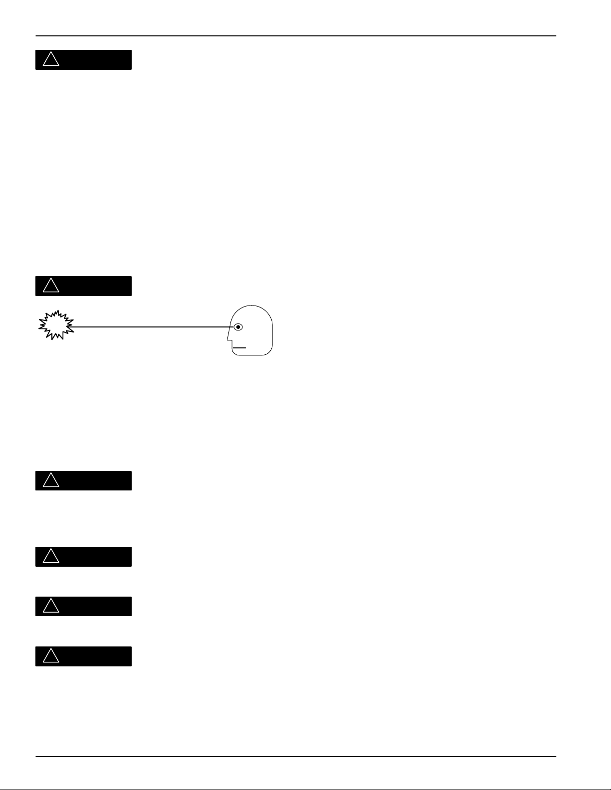
CAUTION
Avoid Laser Beam
This equipment employs a 150 milliwatt laser. Laser radiation may be present when the
machine operates without panels or covers installed.
Use of controls or adjustments, or performance of procedures other than those specified herein, may
result in eye damage.
Covers shall be removed by authorized service personnel only.
!
CAUTION
This equipment is intended to connect to other medical devices. Only qualified service personnel may
perform installation and service maintenance. The laser in the equipment is not a patient device.
Therefore, the equipment must be installed no closer than 1.83 meters from a patient bed or chair.
!
CAUTION
U.S. Federal law restricts this device to the sale by, or on the order of, a licensed health care practitioner.
!
CAUTION
Do not substitute or modify any part of this equipment without approval of Eastman Kodak Company.
!
CAUTION
General External Cleaning: This equipment may be cleaned with a damp cloth using water with mild
detergent, or commercial electronic equipment cleaner.
ii
1202688 2001 March Rev. L
Page 5
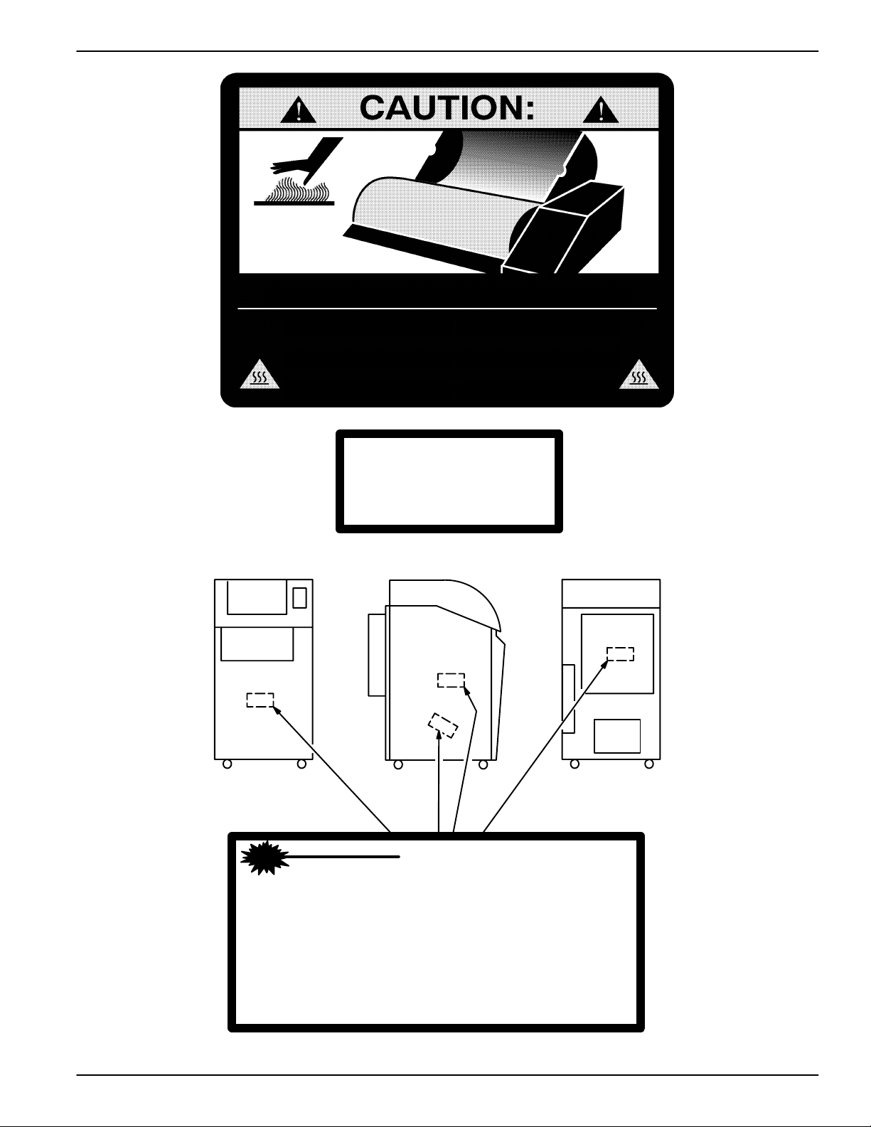
Do not touch, Hot Surface!
Warnings and Cautions
Front
Surface Chaude. Ne pas toucher!
Nicht anfassen. Heisse Oberflache!
ATTENTION:
ACHTUNG:
ATTENZIONE:
Non toccare. Superficie Calda!
Class 1 Laser
Laser de catégorie 1
Laser-Klasse 1
Laser di Classe 1
Klass 1 Laser
Left
CAUTION:
Do not touch. Hot surface!
ADVERTENCIA:
No tocar. Superficia Caliente!
OPGEPAST:
Niet aanraken. Heet Oppervlak!
Rear
DANGER - Invisible Laser Radiation When Open.
Avoid Direct Exposure to Beam.
ATTENTION - Rayonnement Laser Invisible En Cas
D’Ouverture. Exposition Dangereuse
Au Faisceau.
VORSICHT - Unsichtbare Laserstrahlung Wenn Abdeckung
Geöffnet. Nicht Dem Strahl Aussetzen.
VARNING - Osynlig Laserstrålning. Laserstråining När
Denna Del Ä Öppnad. Strålen Är Farlig.
iii2001 March Rev. L 1202688
Page 6
Service Manual
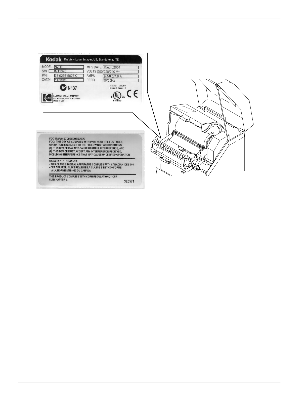
Label located on back of IMAGER.
iv
1202688 2001 March Rev. L
Page 7

Warnings and Cautions for External Interface Box Accessories
Warnings and Cautions for
External Interface Box Accessories
Read and understand all instructions before using.
Classifications
UL Classified
File Number E183646
Control Number 9R46
Medical Equipment
UL 2601-1 CAN/CSA No. 601.1
!
Classified by Underwriters Laboratories Inc. With Respect to Electric Shock, Fire, Casualty and
Medical Hazards only in Accordance with UL 2601-1, CAN/CSA C22.2 No. 601.1 and IEC 601.1.
!
CAUTION
Do not use in the presence of flammable anesthetics, oxygen or nitrous oxide. This equipment does not
have a gas sealed electronics enclosure and could ignite any flammable or explosive gases present in its
environment.
!
WARNING
This equipment is operated with hazardous voltage which can shock, burn, or cause
death.
Remove wall plug before servicing equipment. Never pull on cord to remove from outlet. Grasp plug and
pull to disconnect.
Do not operate equipment with a damaged power cord.
Do not use an extension cord to power this equipment.
Position the power cord so it will not be tripped over or pulled.
Connect this equipment to a grounded outlet.
Use only the power cord supplied with this equipment.
Do not place a portable multiple–socket outlet (power strip) on the floor. Mount the power strip on a wall or
on the underside of a table.
v2001 March Rev. L 1202688
Page 8

Service Manual
!
WARNING
Not protected against ingress of liquids, including bodily fluids.
!
WARNING
For continued protection against fire, replace fuses only with fuses of the same type and fuse rating.
!
WARNING
This equipment is not contained in a sealed cabinet. Therefore, it must not be used in locations where it
can come in contact with liquids, including bodily fluids.
!
CAUTION
This equipment is intended to connect to other medical devices. Only qualified service personnel may
perform installation and service maintenance.
!
CAUTION
U.S. Federal law restricts this device to the sale by, or on the order of, a licensed health care practitioner.
!
CAUTION
Do not substitute or modify any part of this equipment without approval of Eastman Kodak Company.
!
CAUTION
This equipment has been tested and found to comply with the limits for a Class B digital device, pursuant
to part 15 of the FCC rules. Those limits are designed to provide reasonable protection against harmful
interference in a residential installation. This equipment generates, uses, and can radiate radio frequency
energy and, if not installed and used in accordance with the instructions, may cause harmful interference
to radio communications. However, there is no guarantee that interference will not occur in a particular
installation. If this equipment does cause harmful interference to radio or television reception, which can
be determined by turning the equipment off and on, the user is encouraged to try to correct the
interference by one or more of the following measures:
• Reorient or relocate the receiving antenna.
• Increase the separation between the equipment and the receiver.
• Connect the equipment into an outlet on a circuit different from that to which the receiver is connected.
• Consult the dealer or an experienced radio/TV technician for help.
!
CAUTION
General External Cleaning: This equipment may be cleaned with a damp cloth using water with mild
detergent, or commercial electronic equipment cleaner.
Type B Applied Part
vi
1202688 2001 March Rev. L
Page 9

Agency, Regulatory and CE Marking Compliance
Agency, Regulatory and CE Marking Compliance
All agency, regulatory and CE marking information may be found in the User Guide for these models.
vii2001 March Rev. L 1202688
Page 10

Service Manual
BLANK PAGE
viii
1202688 2001 March Rev. L
Page 11

T able of Contents
PLEASE NOTE
The information contained herein is based on the experience and knowledge relating
to the subject matter gained by Eastman Kodak Company prior to publication.
No patent license is granted by this information.
Eastman Kodak Company reserves the right to change this information without notice
and makes no warranty, express or implied, with respect to this information. Kodak
shall not be liable for any loss or damage, including consequential or special
damages, resulting from the use of this information, even if loss or damage is caused
by Kodak’s negligence or other fault.
Table of Contents
Description Page
Revision History a. . . . . . . . . . . . . . . . . . . . . . . . . . . . . . . . . . . . . . . . . . . . . . . .
Warnings and Cautions for Kodak DryView 8700/8500 LASER IMAGER i
Warnings and Cautions for External Interface Box Accessories v. . . .
Agency, Regulatory and CE Marking Compliance vii. . . . . . . . . . . . . . . . . .
Section 1 – Specifications 1-1. . . . . . . . . . . . . . . . . . . . . . . . . . . . . . . . . . . . . . .
1-1. Dimensions 1-1. . . . . . . . . . . . . . . . . . . . . . . . . . . . . . . . . . . . . . . . . . . . . . . . . . . . .
1-2. Electrical 1-1. . . . . . . . . . . . . . . . . . . . . . . . . . . . . . . . . . . . . . . . . . . . . . . . . . . . . . .
1-3. Storage Environment 1-1. . . . . . . . . . . . . . . . . . . . . . . . . . . . . . . . . . . . . . . . . . . .
1-4. Operating Environment 1-1. . . . . . . . . . . . . . . . . . . . . . . . . . . . . . . . . . . . . . . . . .
1-5. Environmental Effects 1-1. . . . . . . . . . . . . . . . . . . . . . . . . . . . . . . . . . . . . . . . . . . .
1-6. Host Control 1-1. . . . . . . . . . . . . . . . . . . . . . . . . . . . . . . . . . . . . . . . . . . . . . . . . . . .
1-7. Keypad 1-2. . . . . . . . . . . . . . . . . . . . . . . . . . . . . . . . . . . . . . . . . . . . . . . . . . . . . . . .
1-8. Cables 1-2. . . . . . . . . . . . . . . . . . . . . . . . . . . . . . . . . . . . . . . . . . . . . . . . . . . . . . . . .
Section 2 – Installation 2-1. . . . . . . . . . . . . . . . . . . . . . . . . . . . . . . . . . . . . . . . . .
2-1. Unpacking 2-1. . . . . . . . . . . . . . . . . . . . . . . . . . . . . . . . . . . . . . . . . . . . . . . . . . . . . .
2-2. Voltage Setup 2-6. . . . . . . . . . . . . . . . . . . . . . . . . . . . . . . . . . . . . . . . . . . . . . . . . . .
2-3. Cable Connections 2-7. . . . . . . . . . . . . . . . . . . . . . . . . . . . . . . . . . . . . . . . . . . . . .
2-3-1. Compact Keypad to TDB/C 2-7. . . . . . . . . . . . . . . . . . . . . . . . . . . . . . . .
2-3-2. Touch-Screen Keypad to KFEIB to TDB/F 2-7. . . . . . . . . . . . . . . . . . . .
2-3-3. Touch-Screen Keypad to UKEIB to TDB/C 2-8. . . . . . . . . . . . . . . . . . .
2-3-4. Host Control to UKEIB to TDB/F 2-10. . . . . . . . . . . . . . . . . . . . . . . . . . . .
2-3-5. Video Source to VEIB to FIB 2-11. . . . . . . . . . . . . . . . . . . . . . . . . . . . . . .
2-3-6. Video Source to VIB 2-12. . . . . . . . . . . . . . . . . . . . . . . . . . . . . . . . . . . . . .
2-3-7. Video Source to EVEIB to FIB 2-13. . . . . . . . . . . . . . . . . . . . . . . . . . . . . .
2-3-8. Digital Source to DEIB to FIB 2-14. . . . . . . . . . . . . . . . . . . . . . . . . . . . . . .
2001 May Rev. M 1202688
ix
Page 12

Service Manual
Description Page
2-3-9. Digital Source to DIB 2-15. . . . . . . . . . . . . . . . . . . . . . . . . . . . . . . . . . . . . .
2-3-10.Kodak DryView 8800 MULTI-INPUT MANAGER or Kodak Digital Science
969 HQ LASER IMAGER to 8700/8500 IMAGER 2-16. . . . . . . . . . . . .
2-4. Switch and Jumper Settings 2-17. . . . . . . . . . . . . . . . . . . . . . . . . . . . . . . . . . . . . .
2-4-1. UKEIB 2-17. . . . . . . . . . . . . . . . . . . . . . . . . . . . . . . . . . . . . . . . . . . . . . . . . . .
2-4-2. Copper TDB 2-18. . . . . . . . . . . . . . . . . . . . . . . . . . . . . . . . . . . . . . . . . . . . .
2-4-3. VEIB 2-19. . . . . . . . . . . . . . . . . . . . . . . . . . . . . . . . . . . . . . . . . . . . . . . . . . . .
2-4-4. VIB 2-20. . . . . . . . . . . . . . . . . . . . . . . . . . . . . . . . . . . . . . . . . . . . . . . . . . . . .
2-4-5. EVEIB 2-21. . . . . . . . . . . . . . . . . . . . . . . . . . . . . . . . . . . . . . . . . . . . . . . . . . .
2-4-6. DEIB 2-22. . . . . . . . . . . . . . . . . . . . . . . . . . . . . . . . . . . . . . . . . . . . . . . . . . . .
2-5. System Configuration 2-23. . . . . . . . . . . . . . . . . . . . . . . . . . . . . . . . . . . . . . . . . . . .
2-5-1. Power Up the IMAGER 2-23. . . . . . . . . . . . . . . . . . . . . . . . . . . . . . . . . . . .
2-5-2. Connect the MPC to the IMAGER 2-23. . . . . . . . . . . . . . . . . . . . . . . . . . .
2-5-3. Set the System Clock 2-24. . . . . . . . . . . . . . . . . . . . . . . . . . . . . . . . . . . . .
2-5-4. Load IMS Parameters 2-24. . . . . . . . . . . . . . . . . . . . . . . . . . . . . . . . . . . . .
2-5-5. Load SCB Parameters 2-25. . . . . . . . . . . . . . . . . . . . . . . . . . . . . . . . . . . .
2-5-6. Load AIQC Parameters 2-25. . . . . . . . . . . . . . . . . . . . . . . . . . . . . . . . . . . .
2-5-7. Load Keypad Parameters 2-25. . . . . . . . . . . . . . . . . . . . . . . . . . . . . . . . . .
2-5-8. Digital Modality Setup 2-26. . . . . . . . . . . . . . . . . . . . . . . . . . . . . . . . . . . . .
2-5-9. Video Modality Setup 2-26. . . . . . . . . . . . . . . . . . . . . . . . . . . . . . . . . . . . . .
2-5-9-1. Inspect Signals from Modality 2-26. . . . . . . . . . . . . . . . . . . . .
2-5-9-2. Enter Rough Video Parameters 2-27. . . . . . . . . . . . . . . . . . .
2-5-9-3. Fine Tune Video Parameters 2-30. . . . . . . . . . . . . . . . . . . . .
2-5-9-4. Set Customer Preferences 2-33. . . . . . . . . . . . . . . . . . . . . . .
2-5-9-5. OEM Monitor Adjustment 2-34. . . . . . . . . . . . . . . . . . . . . . . .
Section 3 – Adjustments 3-1. . . . . . . . . . . . . . . . . . . . . . . . . . . . . . . . . . . . . . . . .
3-1. Processor Temperature 3-1. . . . . . . . . . . . . . . . . . . . . . . . . . . . . . . . . . . . . . . . . .
3-2. Processor Drum Stripper 3-5. . . . . . . . . . . . . . . . . . . . . . . . . . . . . . . . . . . . . . . . .
3-3. Densitometer Calibration 3-7. . . . . . . . . . . . . . . . . . . . . . . . . . . . . . . . . . . . . . . . .
3-4. Density Patch Offset 3-8. . . . . . . . . . . . . . . . . . . . . . . . . . . . . . . . . . . . . . . . . . . . .
3-5. Exit Transport Sensor Actuator 3-9. . . . . . . . . . . . . . . . . . . . . . . . . . . . . . . . . . . .
3-6. Local Panel Display Contrast and Buzzer Volume 3-10. . . . . . . . . . . . . . . . . . .
3-7. Power Supply Voltages 3-11. . . . . . . . . . . . . . . . . . . . . . . . . . . . . . . . . . . . . . . . . .
3-7-1. +5, +17, –17, and +24 VDC Power Supply (PS901) 3-11. . . . . . . . . . .
3-7-2. –5.2 VDC Power Supply (PS902) 3-14. . . . . . . . . . . . . . . . . . . . . . . . . . .
3-8. Multifeed Board (MFB) Actuator 3-16. . . . . . . . . . . . . . . . . . . . . . . . . . . . . . . . . . .
3-9. Multifeed Board (MFB) Actuator (Alternative Adjustment) 3-18. . . . . . . . . . . . .
3-10. Pickup Arm Height Calibration 3-20. . . . . . . . . . . . . . . . . . . . . . . . . . . . . . . . . . . .
x
1202688 2001 May Rev. M
Page 13

T able of Contents
Description Page
3-11. Processor Drum Brushes 3-21. . . . . . . . . . . . . . . . . . . . . . . . . . . . . . . . . . . . . . . . .
Section 4 – Disasssembly/Reassesmbly 4-1. . . . . . . . . . . . . . . . . . . . . . . . . .
4-1. Covers and Panels 4-1. . . . . . . . . . . . . . . . . . . . . . . . . . . . . . . . . . . . . . . . . . . . . .
4-1-1. Front Panel 4-1. . . . . . . . . . . . . . . . . . . . . . . . . . . . . . . . . . . . . . . . . . . . . .
4-1-2. Rear Panel 4-2. . . . . . . . . . . . . . . . . . . . . . . . . . . . . . . . . . . . . . . . . . . . . . .
4-1-3. Right Side Panel 4-4. . . . . . . . . . . . . . . . . . . . . . . . . . . . . . . . . . . . . . . . . .
4-1-4. Electronics Enclosure Cover 4-5. . . . . . . . . . . . . . . . . . . . . . . . . . . . . . .
4-2. Processor/Exit Assembly 4-6. . . . . . . . . . . . . . . . . . . . . . . . . . . . . . . . . . . . . . . . .
4-2-1. Processor Drum 4-6. . . . . . . . . . . . . . . . . . . . . . . . . . . . . . . . . . . . . . . . . .
4-2-2. Processor Rollers 4-8. . . . . . . . . . . . . . . . . . . . . . . . . . . . . . . . . . . . . . . . .
4-2-3. Processor Motor (M301) 4-9. . . . . . . . . . . . . . . . . . . . . . . . . . . . . . . . . . .
4-2-4. Processor Brushes 4-10. . . . . . . . . . . . . . . . . . . . . . . . . . . . . . . . . . . . . . . .
4-2-5. Processor Communication Board (PCB) 4-11. . . . . . . . . . . . . . . . . . . . .
4-2-6. Rotating Processor Board (RPB) 4-12. . . . . . . . . . . . . . . . . . . . . . . . . . . .
4-2-7. Processor Slip Rings 4-13. . . . . . . . . . . . . . . . . . . . . . . . . . . . . . . . . . . . . .
4-2-8. Processor Thermal Fuses 4-14. . . . . . . . . . . . . . . . . . . . . . . . . . . . . . . . . .
4-2-9. Exit Assembly 4-15. . . . . . . . . . . . . . . . . . . . . . . . . . . . . . . . . . . . . . . . . . . .
4-2-10.Exit Motor (M303) 4-16. . . . . . . . . . . . . . . . . . . . . . . . . . . . . . . . . . . . . . . . .
4-2-11.Processor Exit Sensor (SW301) 4-17. . . . . . . . . . . . . . . . . . . . . . . . . . . .
4-2-12. Processor Entrance Sensor (SW302) 4-18. . . . . . . . . . . . . . . . . . . . . . . .
4-2-13. Exit Transport Sensor (SW304) 4-19. . . . . . . . . . . . . . . . . . . . . . . . . . . . .
4-2-14.Densitometer Assembly 4-20. . . . . . . . . . . . . . . . . . . . . . . . . . . . . . . . . . .
4-3. Transport Assembly 4-21. . . . . . . . . . . . . . . . . . . . . . . . . . . . . . . . . . . . . . . . . . . . .
4-3-1. Transport Motor (M402) 4-21. . . . . . . . . . . . . . . . . . . . . . . . . . . . . . . . . . . .
4-3-2. Transport Feed Roll Motor (M401) 4-22. . . . . . . . . . . . . . . . . . . . . . . . . .
4-3-3. Platen Motor (M403) 4-23. . . . . . . . . . . . . . . . . . . . . . . . . . . . . . . . . . . . . .
4-3-4. Platen Entrance Sensor (SW402) 4-24. . . . . . . . . . . . . . . . . . . . . . . . . . .
4-3-5. Platen Exit Sensor (SW403) 4-25. . . . . . . . . . . . . . . . . . . . . . . . . . . . . . . .
4-3-6. Transport Midpoint Sensor (SW404) 4-26. . . . . . . . . . . . . . . . . . . . . . . . .
4-3-7. Transport Feed Sensor (SW405) 4-27. . . . . . . . . . . . . . . . . . . . . . . . . . . .
4-3-8. Tongue Depressor Sensor (SW406) 4-28. . . . . . . . . . . . . . . . . . . . . . . . .
4-3-9. Tongue Depressor Interrupt Switch (SW407) 4-29. . . . . . . . . . . . . . . . .
4-3-10. Tongue Depressor Solenoid (Y401) 4-30. . . . . . . . . . . . . . . . . . . . . . . . .
4-3-11.Transport Feed Roll Solenoid (Y402) 4-31. . . . . . . . . . . . . . . . . . . . . . . .
4-3-12. Gate Solenoid (Y403) 4-32. . . . . . . . . . . . . . . . . . . . . . . . . . . . . . . . . . . . .
4-3-13.Multifeed Board (MFB) 4-33. . . . . . . . . . . . . . . . . . . . . . . . . . . . . . . . . . . .
4-4. Pickup Assembly 4-34. . . . . . . . . . . . . . . . . . . . . . . . . . . . . . . . . . . . . . . . . . . . . . . .
4-4-1. Pickup Module 4-34. . . . . . . . . . . . . . . . . . . . . . . . . . . . . . . . . . . . . . . . . . .
4-4-2. Vacuum Relay (K501) 4-36. . . . . . . . . . . . . . . . . . . . . . . . . . . . . . . . . . . . .
2001 May Rev. M 1202688
xi
Page 14

Service Manual
Description Page
4-4-3. Pickup Motor (M501) 4-37. . . . . . . . . . . . . . . . . . . . . . . . . . . . . . . . . . . . . .
4-4-4. Vacuum Pump (M502) 4-38. . . . . . . . . . . . . . . . . . . . . . . . . . . . . . . . . . . . .
4-4-5. Picker Down Sensor (SW501) 4-39. . . . . . . . . . . . . . . . . . . . . . . . . . . . . .
4-4-6. Film Out Sensor (SW502) 4-40. . . . . . . . . . . . . . . . . . . . . . . . . . . . . . . . . .
4-4-7. Picker Up Sensor (SW503) 4-41. . . . . . . . . . . . . . . . . . . . . . . . . . . . . . . . .
4-4-8. Picker Extended Sensor (SW504) 4-42. . . . . . . . . . . . . . . . . . . . . . . . . . .
4-4-9. Vacuum Solenoid (Y501) 4-43. . . . . . . . . . . . . . . . . . . . . . . . . . . . . . . . . .
4-5. Rollback Assembly 4-44. . . . . . . . . . . . . . . . . . . . . . . . . . . . . . . . . . . . . . . . . . . . . .
4-5-1. Rollback Module 4-44. . . . . . . . . . . . . . . . . . . . . . . . . . . . . . . . . . . . . . . . . .
4-5-2. Rollback Motor (M601) 4-46. . . . . . . . . . . . . . . . . . . . . . . . . . . . . . . . . . . .
4-5-3. Rollback Motor Home Sensor (SW601) 4-47. . . . . . . . . . . . . . . . . . . . . .
4-5-4. Cartridge Open Sensor (SW603) 4-48. . . . . . . . . . . . . . . . . . . . . . . . . . .
4-5-5. Cartridge Present Sensor (SW604) 4-49. . . . . . . . . . . . . . . . . . . . . . . . .
4-5-6. RF Tag Interface Board and RF Reader Board 4-50. . . . . . . . . . . . . . .
4-5-7. RF Antenna Board 4-51. . . . . . . . . . . . . . . . . . . . . . . . . . . . . . . . . . . . . . . .
4-6. Exposure Assembly 4-52. . . . . . . . . . . . . . . . . . . . . . . . . . . . . . . . . . . . . . . . . . . . .
4-6-1. Platen and Optics Module 4-52. . . . . . . . . . . . . . . . . . . . . . . . . . . . . . . . . .
4-6-2. Platen Access Plate 4-53. . . . . . . . . . . . . . . . . . . . . . . . . . . . . . . . . . . . . . .
4-6-3. Platen Bottom Sensor (SW701) 4-54. . . . . . . . . . . . . . . . . . . . . . . . . . . . .
4-6-4. Beam Power Board (BPB) 4-55. . . . . . . . . . . . . . . . . . . . . . . . . . . . . . . . .
4-6-5. Platen Kicker Solenoid (Y706) 4-56. . . . . . . . . . . . . . . . . . . . . . . . . . . . . .
4-6-6. Platen Door Interlock Sensor (SW703) 4-57. . . . . . . . . . . . . . . . . . . . . .
4-6-7. Platen Top Solenoid (Y701) 4-58. . . . . . . . . . . . . . . . . . . . . . . . . . . . . . . .
4-6-8. Platen Alignment Solenoids (Y702 – Y705) 4-59. . . . . . . . . . . . . . . . . .
4-7. Air Filtration System 4-60. . . . . . . . . . . . . . . . . . . . . . . . . . . . . . . . . . . . . . . . . . . . .
4-7-1. Filtration Fan (M801) 4-60. . . . . . . . . . . . . . . . . . . . . . . . . . . . . . . . . . . . . .
4-7-2. Filter Present Switch (SW801) 4-61. . . . . . . . . . . . . . . . . . . . . . . . . . . . . .
4-8. Frame Mounted Parts 4-62. . . . . . . . . . . . . . . . . . . . . . . . . . . . . . . . . . . . . . . . . . . .
4-8-1. Power Distribution Board (PDB) 4-62. . . . . . . . . . . . . . . . . . . . . . . . . . . .
4-8-2. Processor Power Relay (K801) 4-63. . . . . . . . . . . . . . . . . . . . . . . . . . . . .
4-8-3. Local Panel 4-64. . . . . . . . . . . . . . . . . . . . . . . . . . . . . . . . . . . . . . . . . . . . . .
4-8-4. Top Cover Interlock (SW802) 4-65. . . . . . . . . . . . . . . . . . . . . . . . . . . . . . .
4-8-5. Left Door Machine Interlock (SW803) 4-66. . . . . . . . . . . . . . . . . . . . . . . .
4-8-6. Left Door Laser Interlock (SW804) 4-67. . . . . . . . . . . . . . . . . . . . . . . . . .
4-8-7. Power Switch (SW805) 4-68. . . . . . . . . . . . . . . . . . . . . . . . . . . . . . . . . . . .
4-8-8. Supply Door Interlock (SW806) 4-69. . . . . . . . . . . . . . . . . . . . . . . . . . . . .
4-8-9. Supply Door Solenoid (Y801) 4-70. . . . . . . . . . . . . . . . . . . . . . . . . . . . . . .
4-8-10.Left Door Solenoid (Y802) 4-71. . . . . . . . . . . . . . . . . . . . . . . . . . . . . . . . .
4-8-11.Service Switch 4-72. . . . . . . . . . . . . . . . . . . . . . . . . . . . . . . . . . . . . . . . . . .
4-9. Power Module Assembly 4-73. . . . . . . . . . . . . . . . . . . . . . . . . . . . . . . . . . . . . . . . .
xii
1202688 2001 May Rev. M
Page 15

T able of Contents
Description Page
4-9-1. Power Module 4-73. . . . . . . . . . . . . . . . . . . . . . . . . . . . . . . . . . . . . . . . . . . .
4-9-2. Filter Capacitor (C901) and Varistor (V901) 4-74. . . . . . . . . . . . . . . . . .
4-9-3. Input Circuit Breaker (CB901) 4-75. . . . . . . . . . . . . . . . . . . . . . . . . . . . . .
4-9-4. Processor Circuit Breaker (CB902) 4-76. . . . . . . . . . . . . . . . . . . . . . . . . .
4-9-5. Power Supply, Cooling Fans, and Vacuum Pump
Circuit Breaker (CB903) 4-77. . . . . . . . . . . . . . . . . . . . . . . . . . . . . . . . . . .
4-9-6. 24 VAC Circuit Breaker (CB904) 4-78. . . . . . . . . . . . . . . . . . . . . . . . . . . .
4-9-7. Line Filter (LF901) 4-79. . . . . . . . . . . . . . . . . . . . . . . . . . . . . . . . . . . . . . . .
4-9-8. Power Latch Relay (K901) 4-80. . . . . . . . . . . . . . . . . . . . . . . . . . . . . . . . .
4-9-9. Cooling Fan Motor (M901) 4-81. . . . . . . . . . . . . . . . . . . . . . . . . . . . . . . . .
4-9-10.+5, +17, –17, and +24 VDC Power Supply (PS901) 4-82. . . . . . . . . . .
4-9-11.–5.2 VDC Power Supply (PS902) 4-83. . . . . . . . . . . . . . . . . . . . . . . . . . .
4-10. Electronics Enclosure 4-84. . . . . . . . . . . . . . . . . . . . . . . . . . . . . . . . . . . . . . . . . . . .
4-10-1.Translator Daughter Board (TDB) 4-84. . . . . . . . . . . . . . . . . . . . . . . . . . .
4-10-2. Interface Boards (DIB/FIB/SIB/VIB) 4-85. . . . . . . . . . . . . . . . . . . . . . . . .
4-10-3.Image Processor Board (IPB) 4-86. . . . . . . . . . . . . . . . . . . . . . . . . . . . . .
4-10-4.Memory Daughter Board (MDB) 4-87. . . . . . . . . . . . . . . . . . . . . . . . . . . .
4-10-5.System Controller Board (SCB) 4-88. . . . . . . . . . . . . . . . . . . . . . . . . . . . .
4-10-6.Machine Interface Board (MIB) 4-89. . . . . . . . . . . . . . . . . . . . . . . . . . . . .
4-10-7.New Modem Board (NMB) 4-90. . . . . . . . . . . . . . . . . . . . . . . . . . . . . . . . .
4-10-8.Cooling Fan Motors (M1001 – M1003) 4-92. . . . . . . . . . . . . . . . . . . . . . .
Section 5 – Additional Information 5-1. . . . . . . . . . . . . . . . . . . . . . . . . . . . . . .
5-1. Required Tools 5-1. . . . . . . . . . . . . . . . . . . . . . . . . . . . . . . . . . . . . . . . . . . . . . . . . .
5-2. Temperature Meter and Probe Calibration 5-2. . . . . . . . . . . . . . . . . . . . . . . . . .
5-3. Serial Number Label Location 5-2. . . . . . . . . . . . . . . . . . . . . . . . . . . . . . . . . . . . .
5-4. Adapter Cable Pinouts 5-2
5-5. Preventive Maintenance 5-4
5-5-1. Preventive Maintenance Intervals 5-4
5-5-2. Supplies Required for PM 5-4
5-5-3. EM Call Checklist 5-5
5-5-4. 10,000 Cycle Checklist 5-6. . . . . . . . . . . . . . . . . . . . . . . . . . . . . . . . . . . .
5-5-5. 30,000 Cycle (or Yearly) Checklist 5-7. . . . . . . . . . . . . . . . . . . . . . . . . .
5-5-6. Cleaning the Processor 5-8
5-5-7. Cleaning the Platen 5-17
5-5-8. Completing the PM 5-18. . . . . . . . . . . . . . . . . . . . . . . . . . . . . . . . . . . . . . . .
. . . . . . . . . . . . . . . . . . . . . . . . . . . . . . . . . . . . . . . . . . .
. . . . . . . . . . . . . . . . . . . . . . . . . . . . . . . . . . . . . . . . . .
. . . . . . . . . . . . . . . . . . . . . . . . . . .
. . . . . . . . . . . . . . . . . . . . . . . . . . . . . . . . . .
. . . . . . . . . . . . . . . . . . . . . . . . . . . . . . . . . . . . . . . . .
. . . . . . . . . . . . . . . . . . . . . . . . . . . . . . . . . . . .
. . . . . . . . . . . . . . . . . . . . . . . . . . . . . . . . . . . . . . .
2001 May Rev. M 1202688
xiii
Page 16

Service Manual
Description Page
Section 6 – Theory of Operation 6-1. . . . . . . . . . . . . . . . . . . . . . . . . . . . . . . . . .
6-1. Overall System Architecture 6-1. . . . . . . . . . . . . . . . . . . . . . . . . . . . . . . . . . . . . .
6-1-1. Module Architecture 6-1. . . . . . . . . . . . . . . . . . . . . . . . . . . . . . . . . . . . . . .
6-1-2. System Electronics Architecture 6-2. . . . . . . . . . . . . . . . . . . . . . . . . . . .
6-2. Module Descriptions 6-3. . . . . . . . . . . . . . . . . . . . . . . . . . . . . . . . . . . . . . . . . . . . .
6-2-1. Local Panel Assembly 6-3. . . . . . . . . . . . . . . . . . . . . . . . . . . . . . . . . . . . .
6-2-2. Densitometer Assembly 6-3. . . . . . . . . . . . . . . . . . . . . . . . . . . . . . . . . . .
6-2-3. Processor Assembly 6-3. . . . . . . . . . . . . . . . . . . . . . . . . . . . . . . . . . . . . .
6-2-4. Transport Assembly 6-4. . . . . . . . . . . . . . . . . . . . . . . . . . . . . . . . . . . . . . .
6-2-5. Pickup Assembly 6-5. . . . . . . . . . . . . . . . . . . . . . . . . . . . . . . . . . . . . . . . .
6-2-6. Rollback Assembly 6-5. . . . . . . . . . . . . . . . . . . . . . . . . . . . . . . . . . . . . . . .
6-2-7. Exposure Assembly 6-6. . . . . . . . . . . . . . . . . . . . . . . . . . . . . . . . . . . . . . .
6-2-8. Frame Assembly 6-6. . . . . . . . . . . . . . . . . . . . . . . . . . . . . . . . . . . . . . . . . .
6-2-9. Power Module Assembly 6-7. . . . . . . . . . . . . . . . . . . . . . . . . . . . . . . . . . .
6-2-10. Electronic Enclosure Assembly 6-8. . . . . . . . . . . . . . . . . . . . . . . . . . . . .
6-3. Electronics Description 6-9. . . . . . . . . . . . . . . . . . . . . . . . . . . . . . . . . . . . . . . . . . .
6-3-1. Image Management System 6-9. . . . . . . . . . . . . . . . . . . . . . . . . . . . . . .
6-3-1-1. Image Processor Board (IPB) 6-10. . . . . . . . . . . . . . . . . . . . .
6-3-1-2. Bandwidth 6-12. . . . . . . . . . . . . . . . . . . . . . . . . . . . . . . . . . . . .
6-3-1-3. Memory Daughter Board (MDB) 6-12. . . . . . . . . . . . . . . . . . .
6-3-1-4. Translator Daughter Board (TDB) 6-13. . . . . . . . . . . . . . . . .
6-3-1-5. Image Interface Boards (DIB, FIB, VIB) 6-13. . . . . . . . . . . .
6-3-1-6. Digital Interface Board (DIB) 6-14. . . . . . . . . . . . . . . . . . . . . .
6-3-1-7. Fiber Interface Board (FIB) 6-14. . . . . . . . . . . . . . . . . . . . . . .
6-3-1-8. Video Interface Board (VIB) 6-15. . . . . . . . . . . . . . . . . . . . . .
6-3-2. Laser Optics System (LOS) 6-15. . . . . . . . . . . . . . . . . . . . . . . . . . . . . . . .
6-3-2-1. General Description 6-15. . . . . . . . . . . . . . . . . . . . . . . . . . . . .
6-3-2-2. LOS Electronics 6-16. . . . . . . . . . . . . . . . . . . . . . . . . . . . . . . .
6-3-3. Machine Control System (MCS) 6-17. . . . . . . . . . . . . . . . . . . . . . . . . . . .
6-3-3-1. General Description 6-17. . . . . . . . . . . . . . . . . . . . . . . . . . . . .
6-3-3-2. MCS Components 6-17. . . . . . . . . . . . . . . . . . . . . . . . . . . . . .
6-3-3-3. EEA Electronics 6-18. . . . . . . . . . . . . . . . . . . . . . . . . . . . . . . .
6-3-3-4. Machine Interface Board (MIB) 6-18. . . . . . . . . . . . . . . . . . .
6-3-3-5. System Control Board (SCB) 6-19. . . . . . . . . . . . . . . . . . . . .
6-3-3-6. New Modem Board (NMB) 6-20. . . . . . . . . . . . . . . . . . . . . . .
6-3-3-7. RF Tag Subsystem 6-22. . . . . . . . . . . . . . . . . . . . . . . . . . . . . .
6-3-3-8. Interlocks 6-23. . . . . . . . . . . . . . . . . . . . . . . . . . . . . . . . . . . . . .
6-3-4. Operator Interfaces 6-26. . . . . . . . . . . . . . . . . . . . . . . . . . . . . . . . . . . . . . .
6-3-5. System Firmware and Software 6-26. . . . . . . . . . . . . . . . . . . . . . . . . . . . .
xiv
1202688 2001 May Rev. M
Page 17

T able of Contents
Description Page
Section 7 – Troubleshooting 7-1. . . . . . . . . . . . . . . . . . . . . . . . . . . . . . . . . . . . .
7-1. General 7-1. . . . . . . . . . . . . . . . . . . . . . . . . . . . . . . . . . . . . . . . . . . . . . . . . . . . . . . .
7-2. Sensor/Interlock Trouble Analysis 7-1. . . . . . . . . . . . . . . . . . . . . . . . . . . . . . . . .
7-2-1. Sensor Locations 7-1. . . . . . . . . . . . . . . . . . . . . . . . . . . . . . . . . . . . . . . . .
7-2-2. Sensor Troubleshooting 7-2. . . . . . . . . . . . . . . . . . . . . . . . . . . . . . . . . . .
7-2-3. Measuring Sensor Signals at the SCB 7-3. . . . . . . . . . . . . . . . . . . . . . .
7-2-4. Sensor to SCB Schematic 7-5. . . . . . . . . . . . . . . . . . . . . . . . . . . . . . . . .
7-2-5. Interlock Switches 7-6. . . . . . . . . . . . . . . . . . . . . . . . . . . . . . . . . . . . . . . .
7-3. Motor/Solenoid Trouble Analysis 7-7. . . . . . . . . . . . . . . . . . . . . . . . . . . . . . . . . .
7-3-1. Motor Locations 7-7. . . . . . . . . . . . . . . . . . . . . . . . . . . . . . . . . . . . . . . . . .
7-3-2. Motor Troubleshooting 7-8. . . . . . . . . . . . . . . . . . . . . . . . . . . . . . . . . . . . .
7-3-3. Solenoid Locations 7-9. . . . . . . . . . . . . . . . . . . . . . . . . . . . . . . . . . . . . . . .
7-3-4. Solenoid Troubleshooting 7-10. . . . . . . . . . . . . . . . . . . . . . . . . . . . . . . . . .
7-4. Film Sequencing 7-11. . . . . . . . . . . . . . . . . . . . . . . . . . . . . . . . . . . . . . . . . . . . . . . .
7-4-1. Load Cartridge Sequence 7-11. . . . . . . . . . . . . . . . . . . . . . . . . . . . . . . . . .
7-4-2. Open Cartridge Lid 7-12. . . . . . . . . . . . . . . . . . . . . . . . . . . . . . . . . . . . . . . .
7-4-3. Read RF Tag 7-13. . . . . . . . . . . . . . . . . . . . . . . . . . . . . . . . . . . . . . . . . . . . .
7-4-4. Position Pickup Arm 7-14. . . . . . . . . . . . . . . . . . . . . . . . . . . . . . . . . . . . . . .
7-4-5. Pick Up Film 7-15. . . . . . . . . . . . . . . . . . . . . . . . . . . . . . . . . . . . . . . . . . . . .
7-4-6. Move Film to Feed Position 7-16. . . . . . . . . . . . . . . . . . . . . . . . . . . . . . . .
7-4-7. Prepare to Feed Film 7-17. . . . . . . . . . . . . . . . . . . . . . . . . . . . . . . . . . . . . .
7-4-8. Feed Film to Platen Entrance 7-18. . . . . . . . . . . . . . . . . . . . . . . . . . . . . . .
7-4-9. Close Out Pickup Cycle 7-19. . . . . . . . . . . . . . . . . . . . . . . . . . . . . . . . . . . .
7-4-10.Load Film into Platen 7-20. . . . . . . . . . . . . . . . . . . . . . . . . . . . . . . . . . . . . .
7-4-11.Unload Exposed Film from Platen 7-21. . . . . . . . . . . . . . . . . . . . . . . . . . .
7-4-12.Drive Film Up Through Transport 7-22. . . . . . . . . . . . . . . . . . . . . . . . . . .
7-4-13.Drive Film Through Processor to Exit Tray 7-23. . . . . . . . . . . . . . . . . . .
7-5. Error Code Index 7-24. . . . . . . . . . . . . . . . . . . . . . . . . . . . . . . . . . . . . . . . . . . . . . . .
7-6. Troubleshooting QuickSheets 7-27. . . . . . . . . . . . . . . . . . . . . . . . . . . . . . . . . . . . .
2001 May Rev. M 1202688
7-6-1. Error Code Descriptions 7-27. . . . . . . . . . . . . . . . . . . . . . . . . . . . . . . . . . .
7-6-2. EC39: EIB (or IB) not detected by IPB 7-30. . . . . . . . . . . . . . . . . . . . . . .
7-6-3. EC48: No End of File (EOF) 7-31. . . . . . . . . . . . . . . . . . . . . . . . . . . . . . . .
7-6-4. EC59: IPB unable to load parameters to EIB (or IB) 7-32. . . . . . . . . . .
7-6-5. EC64: IPB detected parity error during acquisition 7-34. . . . . . . . . . . .
7-6-6. EC65: Data Overflow or Underflow 7-35. . . . . . . . . . . . . . . . . . . . . . . . . .
7-6-7. EC66: Image memory address has crossed the boundary of available
memory 7-36. . . . . . . . . . . . . . . . . . . . . . . . . . . . . . . . . . . . . . . . . . . . . . . . .
7-6-8. EC67: Too many pixels received from EIB (or IB) 7-37. . . . . . . . . . . . .
7-6-9. EC68: Timeout waiting for pixels from EIB (or IB) 7-39. . . . . . . . . . . . .
xv
Page 18

Service Manual
Description Page
7-6-10.EC68: (Video): Timeout waiting for pixels from EIB (or IB) 7-42. . . . . .
7-6-11.EC75: Local panel failed 7-43. . . . . . . . . . . . . . . . . . . . . . . . . . . . . . . . . . .
7-6-12.EC85: Image memory is full 7-44. . . . . . . . . . . . . . . . . . . . . . . . . . . . . . . .
7-6-13.EC116: Pickup arm could not be moved to proper position 7-45. . . . .
7-6-14.EC121: Optics module attenuator error 7-46. . . . . . . . . . . . . . . . . . . . . .
7-6-15.EC122: Optics module not present 7-47. . . . . . . . . . . . . . . . . . . . . . . . . .
7-6-16.EC123: Optics module temperature error 7-48. . . . . . . . . . . . . . . . . . . .
7-6-17.EC126: SCB unable to detect EOL signal from optics module 7-49. .
7-6-18.EC130: Supply door open 7-50. . . . . . . . . . . . . . . . . . . . . . . . . . . . . . . . .
7-6-19.EC132: No supply cartridge 7-51. . . . . . . . . . . . . . . . . . . . . . . . . . . . . . . .
7-6-20.EC133: Less than 20 sheets remain in supply cartridge 7-52. . . . . . . .
7-6-21.EC134: Supply cartridge empty 7-53. . . . . . . . . . . . . . . . . . . . . . . . . . . . .
7-6-22.EC139: Bad cartridge ID 7-54. . . . . . . . . . . . . . . . . . . . . . . . . . . . . . . . . . .
7-6-23. EC145: Unsupported media type 7-55. . . . . . . . . . . . . . . . . . . . . . . . . . .
7-6-24.EC151: Optics module PLL error 7-56. . . . . . . . . . . . . . . . . . . . . . . . . . . .
7-6-25.EC154: NVRAM error 7-57. . . . . . . . . . . . . . . . . . . . . . . . . . . . . . . . . . . . .
7-6-26.EC161: FiIm jammed on multifeed detector 7-58. . . . . . . . . . . . . . . . . .
7-6-27.EC163: Jam to exposure 7-59. . . . . . . . . . . . . . . . . . . . . . . . . . . . . . . . . .
7-6-28.EC164: Jam exposure 7-60. . . . . . . . . . . . . . . . . . . . . . . . . . . . . . . . . . . . .
7-6-29.EC165: Jam before processor 7-61. . . . . . . . . . . . . . . . . . . . . . . . . . . . . .
7-6-30.EC166: Film pickup problems 7-62. . . . . . . . . . . . . . . . . . . . . . . . . . . . . .
7-6-31. EC173: Platen door open 7-63. . . . . . . . . . . . . . . . . . . . . . . . . . . . . . . . . .
7-6-32.EC176: Supply cartridge could not be opened 7-64. . . . . . . . . . . . . . . .
7-6-33.EC177: Supply cartridge could not be closed 7-65. . . . . . . . . . . . . . . . .
7-6-34. EC178: Top cover open 7-66. . . . . . . . . . . . . . . . . . . . . . . . . . . . . . . . . . . .
7-6-35.EC179: Left side door open 7-67. . . . . . . . . . . . . . . . . . . . . . . . . . . . . . . .
7-6-36.EC202/203: Service override switch out (or fail) 7-68. . . . . . . . . . . . . . .
7-6-37.EC204: Supply door interlock failed 7-69. . . . . . . . . . . . . . . . . . . . . . . . .
7-6-38.EC205: Top cover interlock failed 7-70. . . . . . . . . . . . . . . . . . . . . . . . . . .
7-6-39.EC206: Left side door interlock failed 7-71. . . . . . . . . . . . . . . . . . . . . . . .
7-6-40.EC208: Left side door could not be opened 7-72. . . . . . . . . . . . . . . . . .
7-6-41.EC221: Pickup top sensor failed 7-73. . . . . . . . . . . . . . . . . . . . . . . . . . . .
7-6-42.EC222: Pickup middle sensor failed 7-74. . . . . . . . . . . . . . . . . . . . . . . . .
7-6-43.EC223: Film present sensor failed 7-75. . . . . . . . . . . . . . . . . . . . . . . . . .
7-6-44.EC224: Pickup motor failed 7-76. . . . . . . . . . . . . . . . . . . . . . . . . . . . . . . .
7-6-45.EC225: Cartridge open sensor failed 7-77. . . . . . . . . . . . . . . . . . . . . . . .
7-6-46.EC226: Rollback home sensor failed 7-78. . . . . . . . . . . . . . . . . . . . . . . .
7-6-47.EC227: Rollback motor failed 7-79. . . . . . . . . . . . . . . . . . . . . . . . . . . . . . .
7-6-48. EC228: Tongue depressor sensor failed 7-80. . . . . . . . . . . . . . . . . . . . .
7-6-49.EC229: Supply door could not be opened 7-81. . . . . . . . . . . . . . . . . . . .
xvi
1202688 2001 May Rev. M
Page 19

T able of Contents
Description Page
7-6-50.EC301: HIB parity error 7-82. . . . . . . . . . . . . . . . . . . . . . . . . . . . . . . . . . . .
7-6-51.EC302: HIB register read/write failed 7-83. . . . . . . . . . . . . . . . . . . . . . . .
7-6-52.EC303: HIB lookup table memory failed 7-84. . . . . . . . . . . . . . . . . . . . .
7-6-53.EC501: Processor drum could not be moved 7-85. . . . . . . . . . . . . . . . .
7-6-54.EC506: No communication from processor 7-86. . . . . . . . . . . . . . . . . . .
7-6-55. EC507: Processor returning bad data 7-88. . . . . . . . . . . . . . . . . . . . . . .
7-6-56.EC509: Processor failed to warm up in allotted time 7-89. . . . . . . . . . .
7-6-57.EC511: Processor warming 7-90. . . . . . . . . . . . . . . . . . . . . . . . . . . . . . . .
7-6-58. EC522: Bad densitometer 7-91. . . . . . . . . . . . . . . . . . . . . . . . . . . . . . . . . .
7-6-59.EC542: Jam in processor 7-92. . . . . . . . . . . . . . . . . . . . . . . . . . . . . . . . . .
7-6-60.EC543: Jam in densitometer 7-94. . . . . . . . . . . . . . . . . . . . . . . . . . . . . . .
7-6-61.EC544: Jam at exit 7-95. . . . . . . . . . . . . . . . . . . . . . . . . . . . . . . . . . . . . . . .
7-6-62.EC549: Processor filter not present 7-96. . . . . . . . . . . . . . . . . . . . . . . . .
7-6-63.EC550: Clean processor and replace filter 7-97. . . . . . . . . . . . . . . . . . .
7-6-64.EC551, 552, 553: Processor heater 1, 2, 3 failed 7-98. . . . . . . . . . . . .
7-6-65.EC554: Processor over temp 7-99. . . . . . . . . . . . . . . . . . . . . . . . . . . . . . .
7-6-66. EC561: Invalid densitometer data 7-100. . . . . . . . . . . . . . . . . . . . . . . . . . .
7-6-67.EC601: Invalid power monitor offset 7-101. . . . . . . . . . . . . . . . . . . . . . . . .
7-6-68.EC602: Invalid power monitor range 7-102. . . . . . . . . . . . . . . . . . . . . . . .
7-6-69.EC603: Invalid optical density range 7-103. . . . . . . . . . . . . . . . . . . . . . . .
7-6-70.EC604: Invalid laser dynamic range 7-104. . . . . . . . . . . . . . . . . . . . . . . . .
7-6-71. EC605: Attenuator test failed 7-105. . . . . . . . . . . . . . . . . . . . . . . . . . . . . . .
7-6-72.EC620: No film model found 7-106. . . . . . . . . . . . . . . . . . . . . . . . . . . . . . .
7-6-73.EC622: Corrupt film tables 7-107. . . . . . . . . . . . . . . . . . . . . . . . . . . . . . . . .
7-6-74. EC623: Bad transfer function 7-108. . . . . . . . . . . . . . . . . . . . . . . . . . . . . . .
7-6-75. EC624: Bad densitometer data 7-109. . . . . . . . . . . . . . . . . . . . . . . . . . . . .
7-6-76.EC625: Bad film contrast 7-110. . . . . . . . . . . . . . . . . . . . . . . . . . . . . . . . . .
7-6-77.EC631: Film slow 7-111. . . . . . . . . . . . . . . . . . . . . . . . . . . . . . . . . . . . . . . . .
7-6-78.EC632: Film fast 7-112. . . . . . . . . . . . . . . . . . . . . . . . . . . . . . . . . . . . . . . . . .
7-6-79.EC633: System near calibration limits (film almost fast) 7-113. . . . . . . .
7-6-80.EC634: System near calibration limits (film almost slow) 7-114. . . . . . .
7-6-81.EC635: Dpatch slow 7-115. . . . . . . . . . . . . . . . . . . . . . . . . . . . . . . . . . . . . .
7-6-82.EC636: Dpatch fast 7-116. . . . . . . . . . . . . . . . . . . . . . . . . . . . . . . . . . . . . . .
7-6-83. EC910: Printer Malfunction 7-117. . . . . . . . . . . . . . . . . . . . . . . . . . . . . . . . .
7-6-84.EC913: HIB parity error 7-121. . . . . . . . . . . . . . . . . . . . . . . . . . . . . . . . . . . .
7-7. General System Process Problems 7-122. . . . . . . . . . . . . . . . . . . . . . . . . . . . . . . .
2001 May Rev. M 1202688
7-7-1. SCB Power Up/ Not Ready 7-122. . . . . . . . . . . . . . . . . . . . . . . . . . . . . . . .
7-7-2. Image Acquisition 7-122. . . . . . . . . . . . . . . . . . . . . . . . . . . . . . . . . . . . . . . . .
7-7-3. Film Transport 7-123. . . . . . . . . . . . . . . . . . . . . . . . . . . . . . . . . . . . . . . . . . . .
7-7-4. Print Queue 7-124. . . . . . . . . . . . . . . . . . . . . . . . . . . . . . . . . . . . . . . . . . . . . .
xvii
Page 20

Service Manual
Description Page
7-7-5. Processor 7-125. . . . . . . . . . . . . . . . . . . . . . . . . . . . . . . . . . . . . . . . . . . . . . . .
7-7-6. AIQC 7-125. . . . . . . . . . . . . . . . . . . . . . . . . . . . . . . . . . . . . . . . . . . . . . . . . . . .
7-8. Host Keypad Communications Trouble Analysis 7-126. . . . . . . . . . . . . . . . . . . . .
7-8-1. 8700/8500 Keypad 7-126. . . . . . . . . . . . . . . . . . . . . . . . . . . . . . . . . . . . . . . .
7-8-2. HQ Keypad 7-126. . . . . . . . . . . . . . . . . . . . . . . . . . . . . . . . . . . . . . . . . . . . . .
7-8-3. 8800 Local Panel 7-126. . . . . . . . . . . . . . . . . . . . . . . . . . . . . . . . . . . . . . . . .
7-9. MPC Trouble Analysis 7-127. . . . . . . . . . . . . . . . . . . . . . . . . . . . . . . . . . . . . . . . . . .
7-10. Image Quality Trouble Analysis 7-127. . . . . . . . . . . . . . . . . . . . . . . . . . . . . . . . . . .
7-11. RF Tag Subsystem Trouble Analysis 7-128. . . . . . . . . . . . . . . . . . . . . . . . . . . . . . .
Section 8 – Illustrated Parts Breakdown 8-1. . . . . . . . . . . . . . . . . . . . . . . . . .
8-1. Illustrated Parts Breakdown (IPB) 8-1. . . . . . . . . . . . . . . . . . . . . . . . . . . . . . . . .
Figure 8-1. Machine and Skins Assembly (Screen 1 of 2) 8-3. . . . . . . . . . . . .
Figure 8-2. Machine Assembly (Screen 1 of 12) 8-7. . . . . . . . . . . . . . . . . . . . .
Figure 8-3. Hood Assembly 8-22. . . . . . . . . . . . . . . . . . . . . . . . . . . . . . . . . . . . . . .
Figure 8-4. Front Panel Assembly 8-24. . . . . . . . . . . . . . . . . . . . . . . . . . . . . . . . .
Figure 8-5. FD Latch Assembly 8-26. . . . . . . . . . . . . . . . . . . . . . . . . . . . . . . . . . .
Figure 8-6. Filter Housing Assembly 8-28. . . . . . . . . . . . . . . . . . . . . . . . . . . . . . .
Figure 8-7. Rollback Assembly, RF Tag 8-30. . . . . . . . . . . . . . . . . . . . . . . . . . . .
Figure 8-8. Rollback Cartridge Sensor Assembly 8-32. . . . . . . . . . . . . . . . . . . .
Figure 8-9. Rollback Carriage Assembly 8-34. . . . . . . . . . . . . . . . . . . . . . . . . . . .
Figure 8-10. Pickup Module Assembly 8-36. . . . . . . . . . . . . . . . . . . . . . . . . . . . .
Figure 8-11. Plate Wrist Assembly 8-38. . . . . . . . . . . . . . . . . . . . . . . . . . . . . . . . .
Figure 8-12. Transport Module Assembly (Screen 1 of 4) 8-41. . . . . . . . . . . . .
Figure 8-13. Exposure Module Assembly 8-48. . . . . . . . . . . . . . . . . . . . . . . . . . .
Figure 8-14. Platen Assembly 8-50. . . . . . . . . . . . . . . . . . . . . . . . . . . . . . . . . . . . .
Figure 8-15. Processor Entrance Assembly 8-54. . . . . . . . . . . . . . . . . . . . . . . . .
Figure 8-16. Processor Assembly 8-56. . . . . . . . . . . . . . . . . . . . . . . . . . . . . . . . .
Figure 8-17. Processor Frame Assembly 8-59
Figure 8-18. Processor Drum Assembly 8-60
Figure 8-19. Film Stripper Assembly 8-62
Figure 8-20. Exit Assembly 8-64
. . . . . . . . . . . . . . . . . . . . . . . . . . . . . . . . . . . . . . .
Figure 8-21. Power Module Assembly 8-66
Figure 8-22. Electronics Enclosure Assembly, Standalone (Screen 1 of 2) 8-69
Figure 8-23. Electronics Enclosure Assembly, Dual (Screen 1 of 2) 8-73. . . .
Figure 8-24. Electronics Fan Assembly 8-77
Figure 8-25. External System Interfaces/Cabling 8-78
. . . . . . . . . . . . . . . . . . . . . . . . . . .
. . . . . . . . . . . . . . . . . . . . . . . . . . . .
. . . . . . . . . . . . . . . . . . . . . . . . . . . . . . .
. . . . . . . . . . . . . . . . . . . . . . . . . . . . . .
. . . . . . . . . . . . . . . . . . . . . . . . . . . . .
. . . . . . . . . . . . . . . . . . . .
xviii
Section 9 – Diagrams 9-1. . . . . . . . . . . . . . . . . . . . . . . . . . . . . . . . . . . . . . . . . . . .
9-1. Diagrams 9-1. . . . . . . . . . . . . . . . . . . . . . . . . . . . . . . . . . . . . . . . . . . . . . . . . . . . . . .
1202688 2001 May Rev. M
Page 21

Section 1 – Specifications
Section 1 – Specifications
1-1. Dimensions
Height: 1279 mm (50.4 in.) – Top Cover closed 1641 mm (64.6 in.) – Top Cover open
Width: 661 mm (26.0 in.) – Left Door closed
1218 mm (47.9 in.) – Left Door open
Depth: 813 mm (32.0 in.) – Supply and Filter Doors closed
1392 mm (54.9 in.) – Supply and Filter Doors open
Weight: 250 kg (550 lbs)
1-2. Electrical
Voltage: 200/220/240 VAC " 10%
50/60 Hz " 3%
Current Draw: 9 Amperes (maximum)
Power Consumption: 1800 watts (maximum) during warm up
1-3. Storage Environment
Temperature: –35° to 60°C (–31° to 140°F)
Humidity: 10% to 90% RH, Noncondensing
1-4. Operating Environment
Temperature: 15° to 35°C (59° to 95°F)
Humidity: 20% to 85% RH, Noncondensing
Vibration: 0.01 Gs (maximum)
Magnetic Field: v 100 Gauss
Leveling: 2 degrees or 3/4 inch difference maximum from front to back and side to side
1-5. Environmental Effects
Heat Load: 2300 BTU/Hr (average)
Floor Load: 200 lb/ft
Acoustical Noise: 55 dB at one meter
(70 dB momentarily)
2
(976 kg/m2)
1-6. Host Control
• RS232 or RS422 (jumper selectable) connection to IMAGER or UKEIB.
• Can be located up to one kilometer (3280 feet) from IMAGER when using a UKEIB and fiber cable.
2001 March Rev. L 1202688
1-1
Page 22

Service Manual
1-7. Keypad
• Available image formats include 1:1, 2:1, 4:1, 6:1, 9:1, 12:1, 15:1, 16:1, and 20:1, as well as up to
4 custom formats (for custom formats, images in the same row must all be the same format).
• Images can be acquired and stored in random or sequential order.
• Can be located up to one kilometer (3280 feet) from IMAGER (fiber cable).
1-8. Cables
• Keypad: Not plenum rated
3 m (10 ft.), 10 m (33 ft.)
30 m (98 ft.), 60 m (197 ft.)
• RS232: Supplied by OEM
Not plenum rated
15 ft.
• Digital: Plenum rated
3 m (10 ft.), 10 m (33 ft.)
30 m (98 ft.), 60 m (197 ft.)
• Analog: Plenum rated
3 m (10 ft.), 10 m (33 ft.)
30 m (98 ft.), 60 m (197 ft.)
• Fiber Optic: Plenum rated
3 m (10 ft.), 10 m (33 ft.)
30 m (98 ft.), 60 m (197 ft.)
100 m (330 ft.), 150 m (490 ft.)
200 m (653 ft.), 250 m (816 ft.)
300 m (1090 ft.), 500 m (1652 ft.)
• Characteristics:
Fiber (glass): 62./125 µm
Bandwidth: 160 MHz/km
Attenuation < 4 db/km at 850 nm
Test attenuation per FOTP 171 S–T Connector
1-2
1202688 2001 March Rev. L
Page 23
Section 2 – Installation
Section 2 – Installation
2-1. Unpacking
Note
Steps 1 through 7 of this procedure can be performed by dock personnel or a Kodak-trained
technician. Steps 8 through 32 must be performed by a Kodak-trained technician.
Note
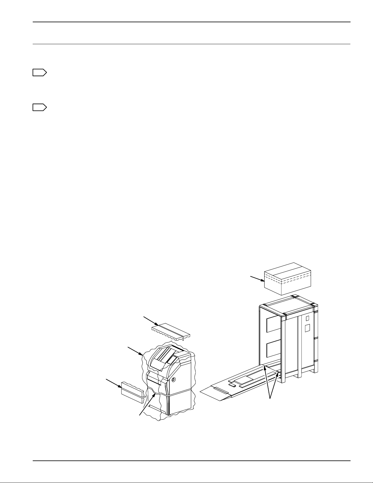
Refer to Figure 2-1 while performing steps 1 through 7 of this procedure.
1. Remove the accessories box from the top of the shipping crate.
2. Remove the wire clamps that secure the front panel of the shipping crate, then remove the front panel.
3. Install the front panel as a ramp:
a. Lay the front panel down in front of the crate.
b. Unfold the small ramp at the top end of the front panel.
c. Set the bottom end of the front panel on the front edge of the crate. Align the holes in the panel
with the holes in the crate.
d. Use the two bolts stored underneath the IMAGER to secure the ramp to the crate.
4. Remove the foam packing from the front and top of the IMAGER.
5. Grasp the tape handle on the front of the IMAGER. Slowly pull the IMAGER out of the crate and ease
it down the ramp.
6. Remove the filter from the crate.
7. Roll the IMAGER to the installation location.
Accessories Box
Foam Packing
Plastic Bag
Foam Packing
2001 March Rev. L 1202688
Ramp Bolts
Tape Handle
Figure 2-1.
2-1
Page 24
Service Manual
Note
The remaining steps of this procedure must be performed by a Kodak-trained technician.
8. Remove the plastic bag from the IMAGER.
9. Remove the power cord, warranty, User Guide, and installation kit from the exit tray.
10. Remove all the filament tape from the exterior of the IMAGER.
11. Remove the plastic sheet from the local panel.
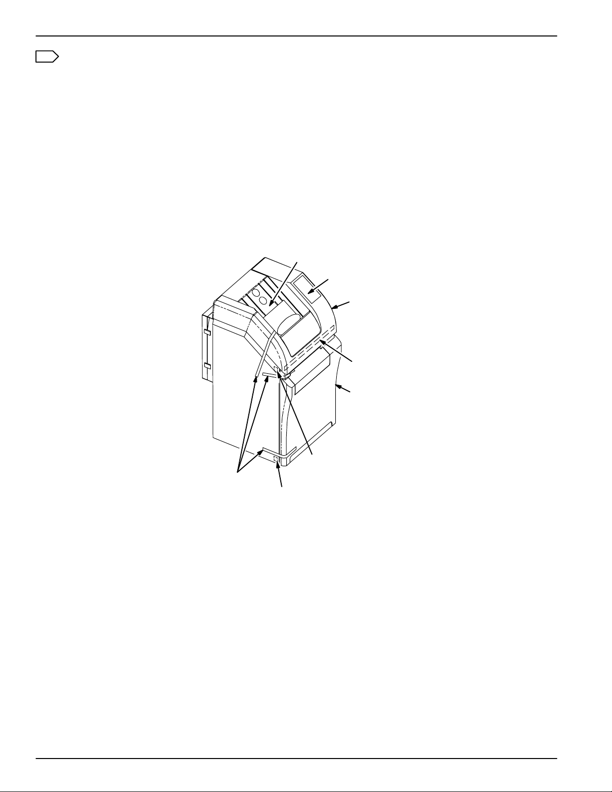
12. Open the top cover.
13. Open the left side and supply doors via their mechanical releases.
14. To gain access to the shipping screw on the right side of the exposure module:
a. Remove the bracket (three screws) that secures the top edge of the front cover.
b. Lift the front cover up and away from the frame.
Exit Tray
Local Panel
Top Cover
Filament Tape
Bracket
Front Cover
Supply Door
Mechanical Release
Left Side Door
Mechanical Release
Figure 2-2.
2-2
1202688 2001 March Rev. L
Page 25
Section 2 – Installation
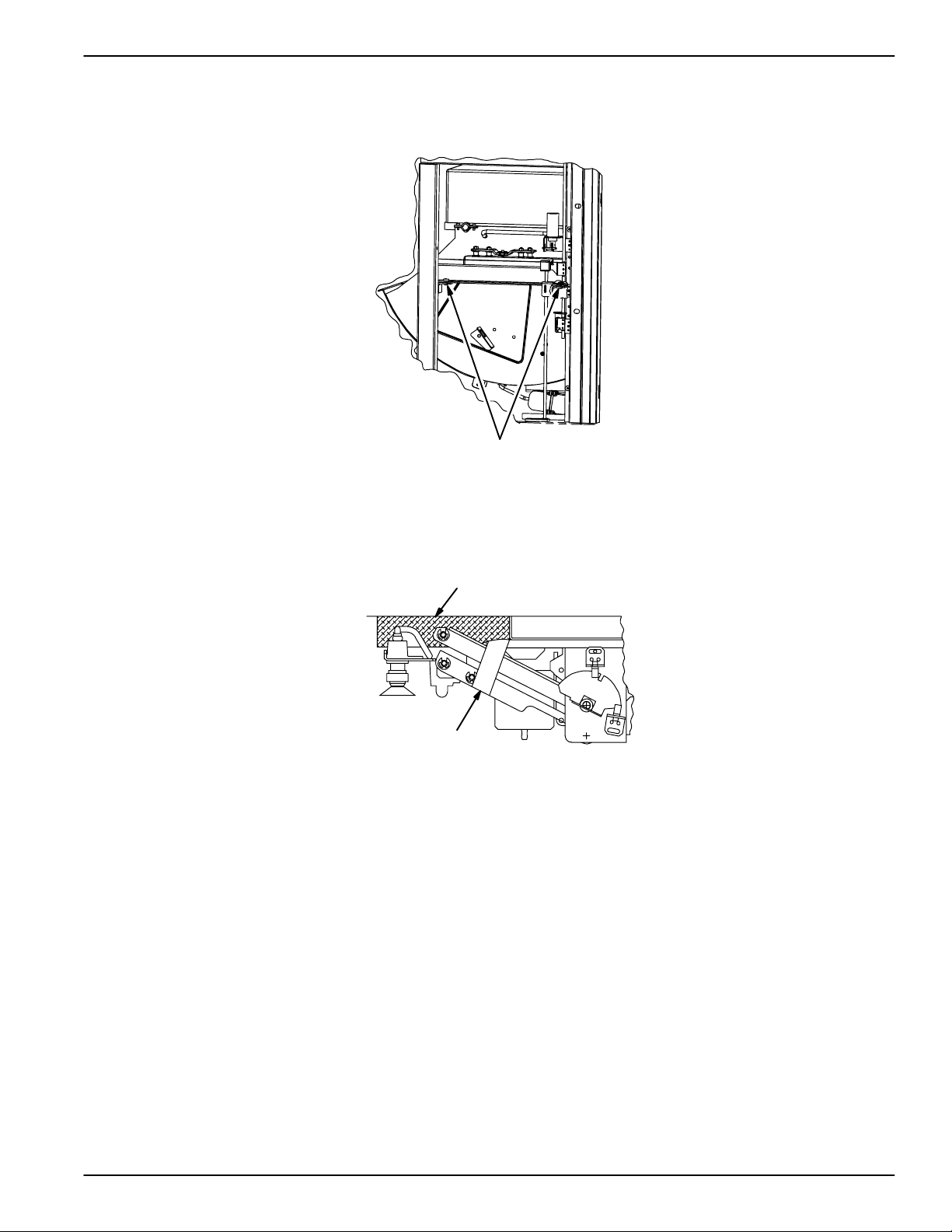
15. Use a 4 mm ball-end Allen wrench to remove the three shipping screws that secure the exposure
module to the frame. There are two screws on the left side and one on the right (front). Discard the
screws.
Shipping Screws
Figure 2-3.
16. Remove the filament tape from the pickup arms.
17. Pull the pickup arms down and remove the foam block located above the pickup assembly.
Foam Block
Filament Tape
Figure 2-4.
18. Remove the filament tape from the rollback handle.
19. Remove the filament tape from the wood block that is located between the frame and the transport
assembly, then remove the wood block.
2001 March Rev. L 1202688
2-3
Page 26
Service Manual
Rollback Handle
Filament Tape
Wood Block
Figure 2-5.
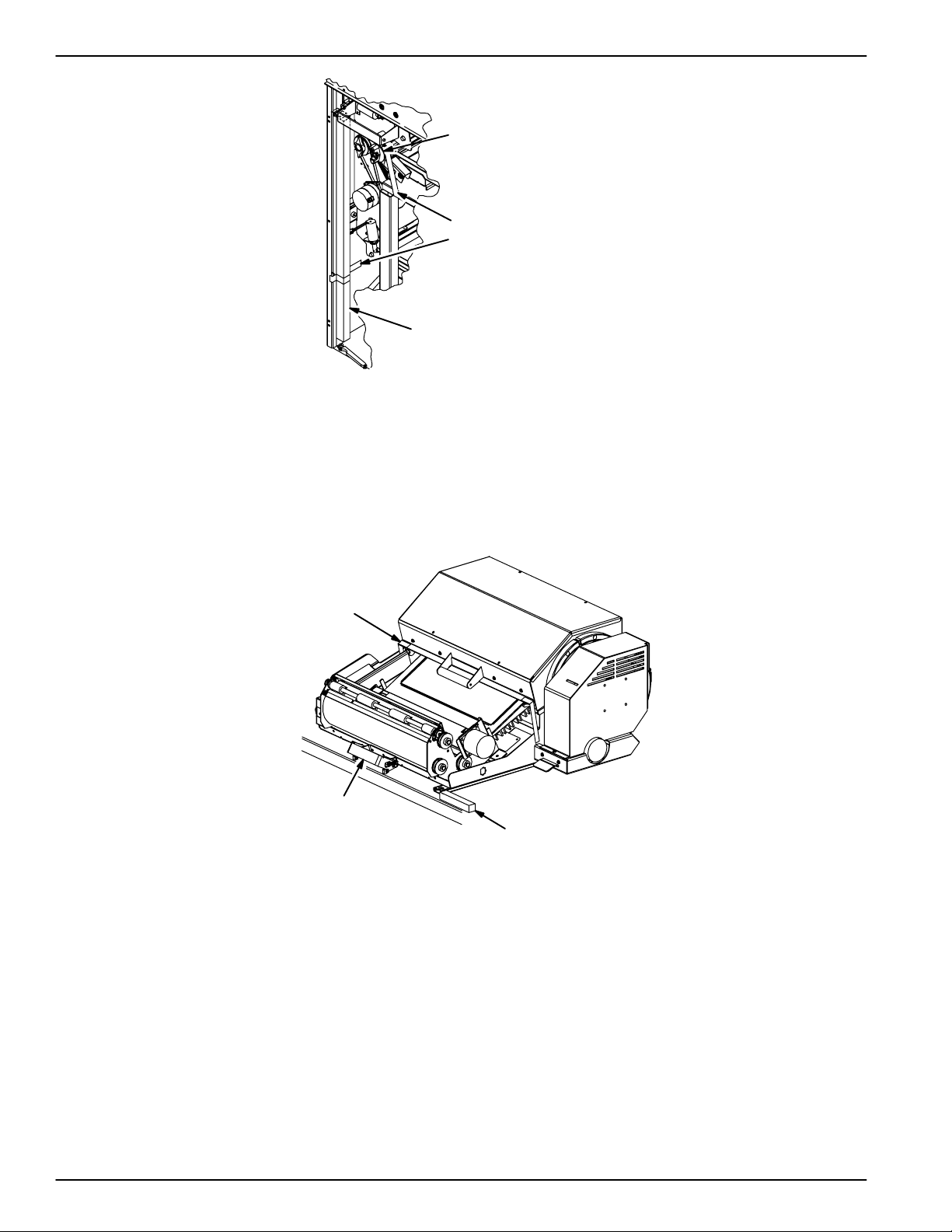
20. Remove the yellow caution tag from the handle on the transport assembly.
21. Release the processor latch and slide it to the right.
22. Grasp the handle on the front of the processor/exit assembly and pull the assembly out to its
extended position.
23. Remove the filament tape from both ends of the processor cover.
Filament Tape
(Both Ends)
Handle
Processor Latch
Figure 2-6.
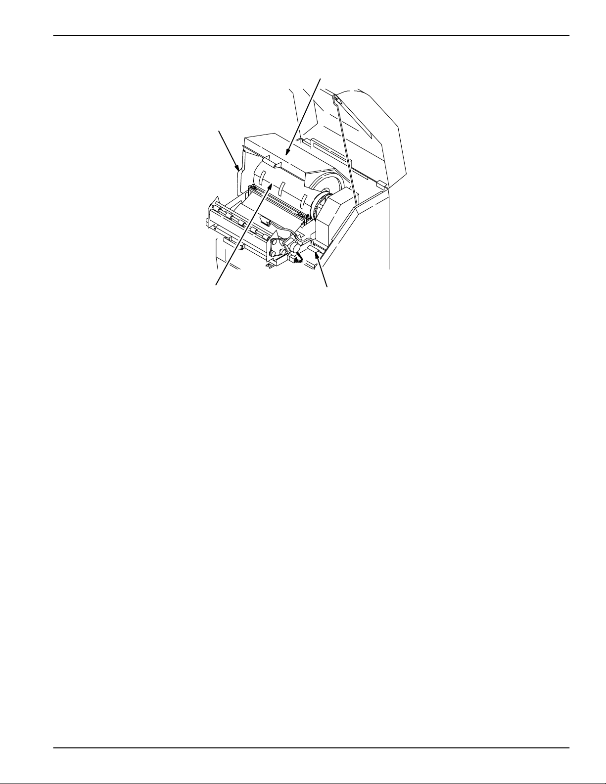
24. Open the processor cover.
25. Remove the tape from the foam sheet that is wrapped around the drum, then slowly pull the foam
sheet out of the processor.
26. Close the processor cover by lifting the cover slightly and pulling the support arm forward.
27. Press the blue release lever on the right side of the processor, then slide the processor/exit assembly
back into place.
28. Slide the processor latch to the left to secure the processor/exit assembly.
29. Install the front cover and bracket.
30. Close the supply door and left side door.
31. Close the top cover by lifting the cover slightly and pushing the support rod backward.
2-4
1202688 2001 March Rev. L
Page 27
32. Install the charcoal filter in housing at back of machine.
Processor Cover
Support Arm
Foam Sheet Release Lever
Figure 2-7.
Section 2 – Installation
8700-113C
2001 March Rev. L 1202688
2-5
Page 28
Service Manual
2-2. Voltage Setup
!
Caution
The IMAGER can be configured to connect with 200, 220, or 240 VAC power sources. Before
applying power, ensure that the IMAGER is set for the voltage that most closely matches the AC
line voltage.
1. Measure the AC voltage at the wall outlet.
2. Remove the tag from the handle of the power module at the rear of the IMAGER. The tag indicates
the factory set voltage. If this setting does not match the line voltage, perform the remaining steps of
this procedure.
!
Warning
When the power cord is plugged in, hazardous voltages are present in some areas of the IMAGER.
These voltages can cause severe injury or death.
3. Flip down the circuit breaker on the rear of the IMAGER, then unplug the power cord.
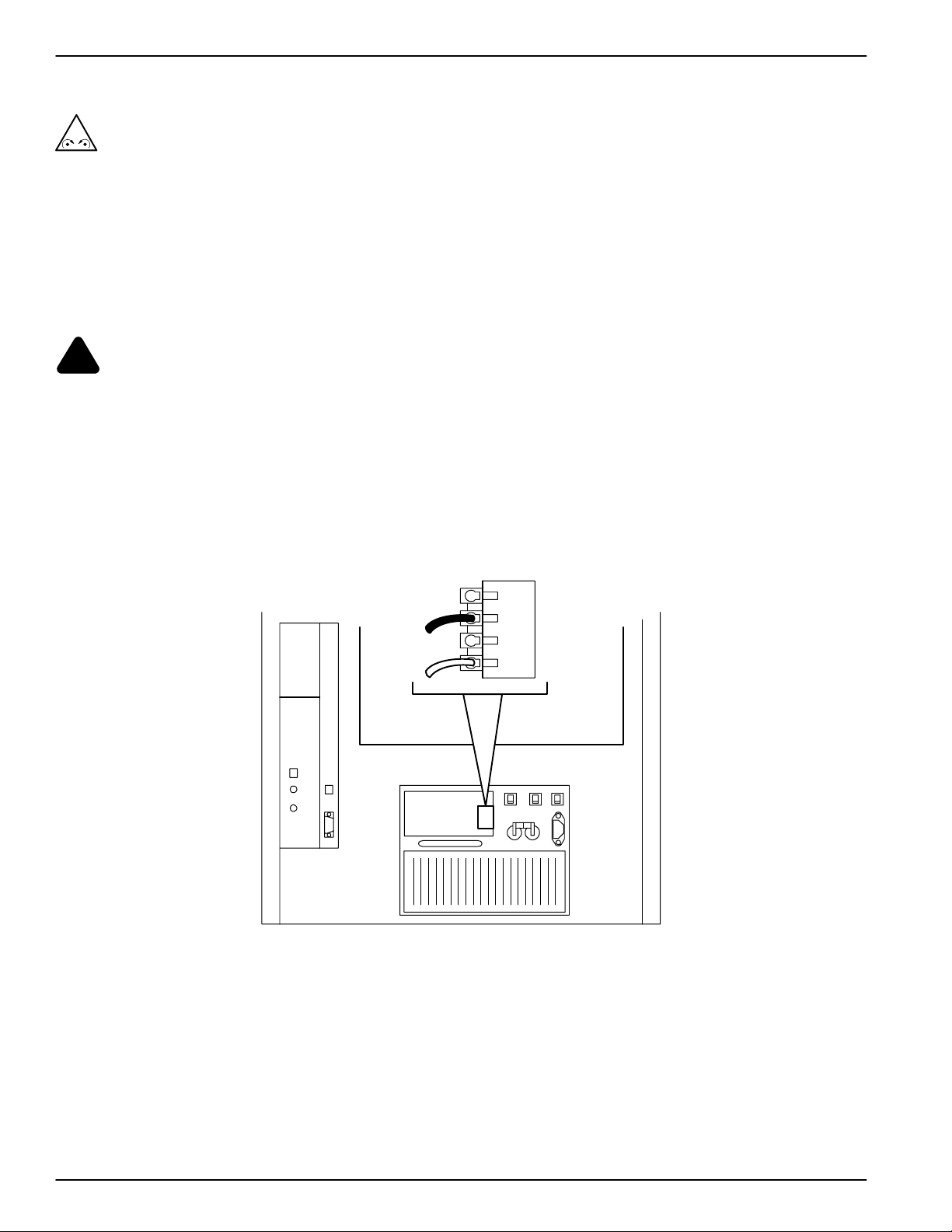
4. Remove the ventilation plate from the upper left corner of the power module (to gain access to the
terminal block above the transformer). Refer to Figure 2-8.
5. Move the black wire to the terminal that most closely matches the AC line voltage.
6. Replace the ventilation plate.
240
220
200
0
Figure 2-8.
2-6
1202688 2001 March Rev. L
Page 29
Section 2 – Installation
2-3. Cable Connections 2-3-1. Compact Keypad to TDB/C
Note
The compact keypad is no longer available, but may still be on site in some customer locations.
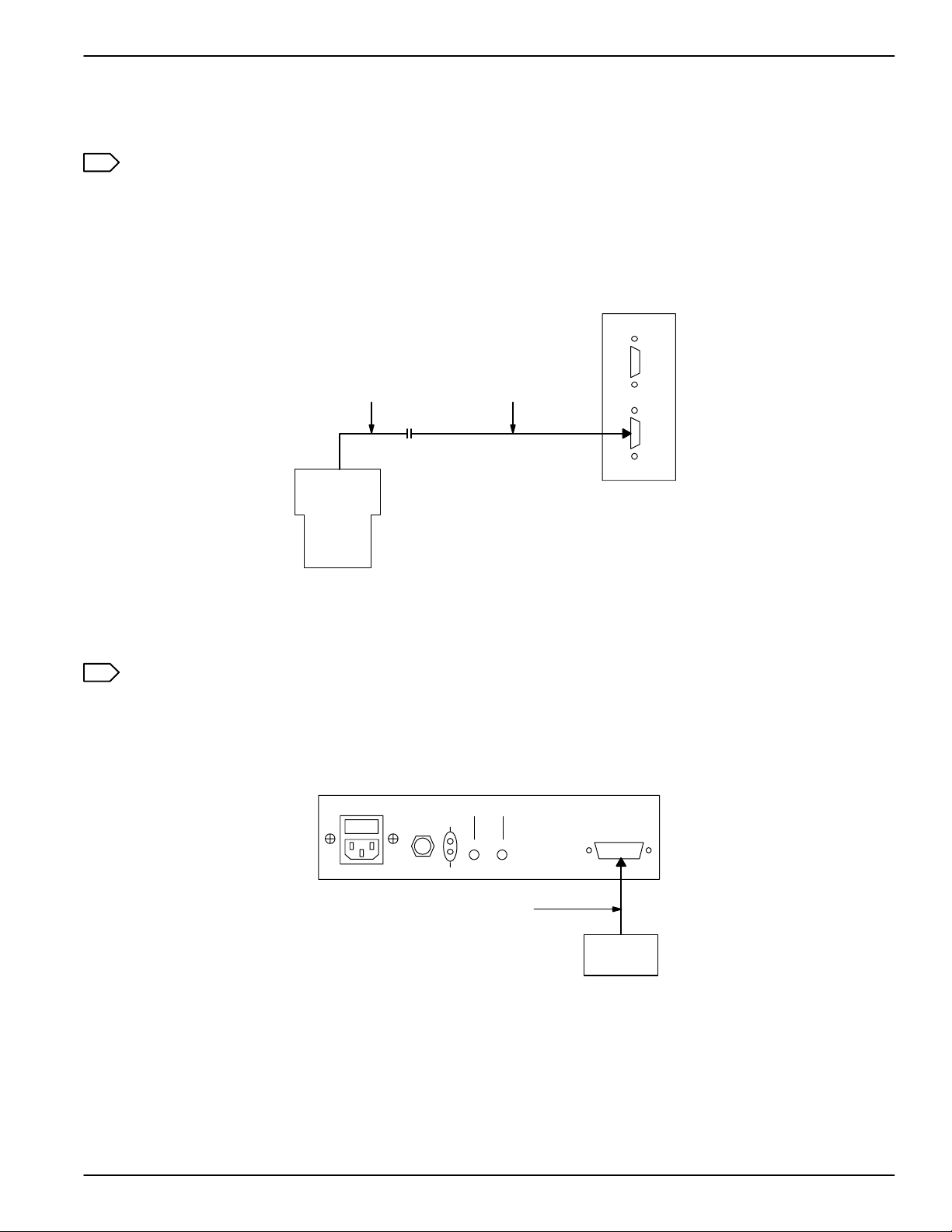
1. If a keypad extension cable is being used, connect it to the compactkeypad cable. Refer to Figure 2-9.
2. Connect the keypad cable (or keypad extension cable) to the TDB/C at the rear of the IMAGER. Refer
to Figure 2-9.
TDB/C
COMM 1
.
.
.
.
.
.
.
.
.
COMM 0
.
.
.
.
.
.
.
.
.
Keypad
Cable
Compact
Keypad
Keypad
Extension
Cable
Figure 2-9.
2-3-2. Touch-Screen Keypad to KFEIB to TDB/F
Note
The KFEIB (Keypad/Fiber External Interface Box) only supports touch-screen keypad users. A
UKEIB is required for host control users.
1. Connect the keypad cable to the keypad and the KFEIB. Refer to Figure 2-10.
KFEIB
FIBER OPTIC
XMT
FTSW
A-CH B-CH
RCV
Keypad Cable
Figure 2-10.
KEYPAD
..........
.........
........
Keypad
2001 March Rev. L 1202688
2-7
Page 30
Service Manual
2. If an optional footswitch is to be used, connect it to the KFEIB. Refer to Figure 2-11.
KFEIB
FIBER OPTIC
XMT
FTSW
A-CH B-CH
RCV
Footswitch
KEYPAD
..........
.........
........
Figure 2-11.
3. Connect the fiber optic cable to the KFEIB. Refer to Figure 2-12.
4. Connect the fiber optic cable to the TDB/F at the rear of the IMAGER. Refer to Figure 2-12.
KFEIB
FIBER OPTIC
XMT
FTSW
A-CH B-CH
RCV
KEYPAD
..........
.........
........
A-Lead
Fiber
Optic
Cable
B-Lead
A-Lead
B-Lead
TDB/F
A0
B0A1 B1
COMM 0COMM 1
Figure 2-12.
5. Connect the KFEIB power cord. For installations outside the U.S. and Canada, the KFEIB is supplied
with a harmonized power cord with no wall plug. For these locations, attach the proper type plug
(obtain locally). The KFEIB uses a universal power supply that requires no modification for input
voltages in the range of 100 to 240 VAC (50/60 Hz).
2-3-3. Touch-Screen Keypad to UKEIB to TDB/C
!
Caution
The switches in the UKEIB must be set before any cables are connected to it. Use only approved
cables and ensure that the cables are connected to the proper connectors on the UKEIB. If the
switches are not set correctly when cables are connected, or unapproved cables are used, or
cables are connected incorrectly, components within the UKEIB may be damaged.
1. Set the switches in the UKEIB (Universal Keypad External Interface Box) as required. Refer to
Procedure 2-4-1.
2. Connect the keypad cable to the keypad and the UKEIB. Refer to Figure 2-13.
3. If an optional footswitch is to be used, connect it to the UKEIB. Refer to Figure 2-14.
2-8
1202688 2001 March Rev. L
Page 31

XMT
FTSW
RCV
Keypad Cable
Figure 2-13.
XMT
FTSW
RCV
Footswitch
UKEIB
FIBER OPTIC
A-CH B-CH
UKEIB
FIBER OPTIC
A-CH B-CH
HOST
.....
....
IMAGER
.....
....
HOST
.....
....
IMAGER
.....
....
KEYPAD
..........
.........
........
Keypad
KEYPAD
..........
.........
........
Section 2 – Installation
Figure 2-14.
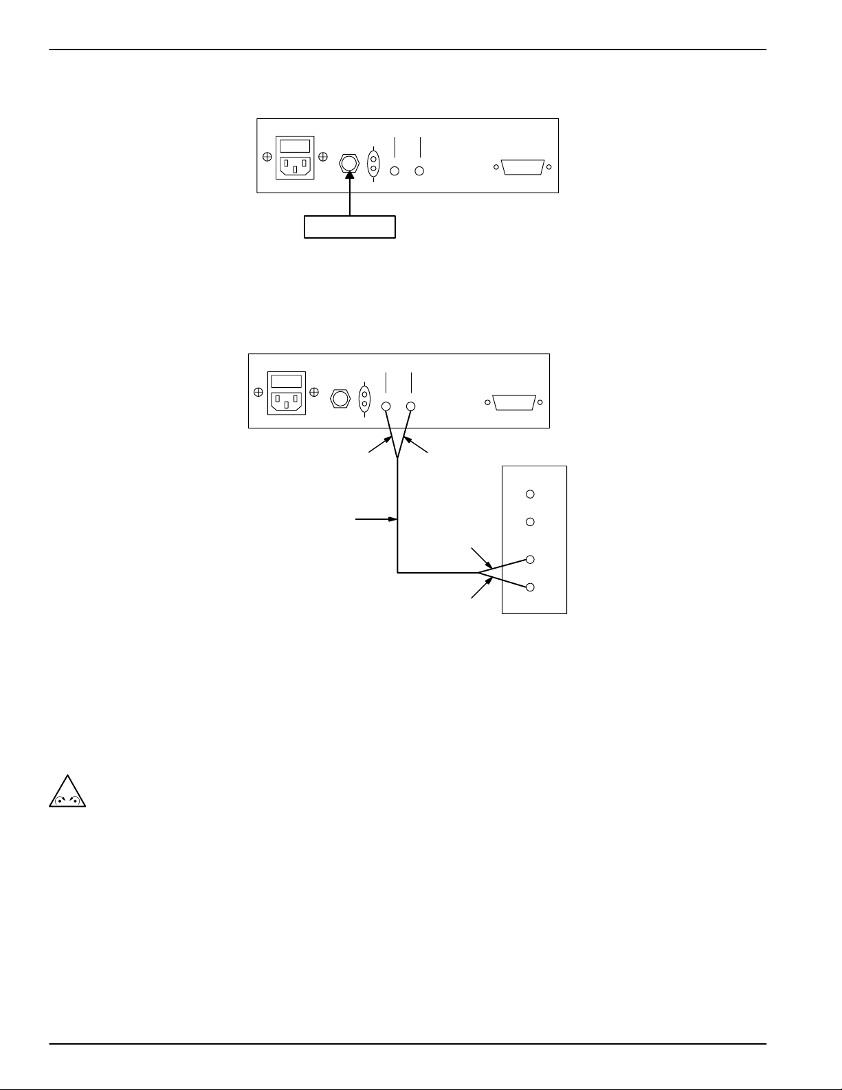
4. Connect the KEIB cable to the UKEIB. Refer to Figure 2-15.
5. Connect the KEIB cable to the TDB/C at the rear of the IMAGER. Refer to Figure 2-15.
6. Connect the UKEIB power cord. For installations outside the U.S. and Canada, the UKEIB is supplied
with a harmonized power cord with no wall plug. For these locations, attach the proper type plug
(obtain locally). The UKEIB uses a universal power supply that requires no modification for input
voltages in the range of 100 to 240 VAC (50/60 Hz).
UKEIB
FTSW
FIBER OPTIC
XMT
RCV
KEIB
Cable
A-CH B-CH
HOST
.....
....
IMAGER
.....
....
KEYPAD
..........
.........
........
TDB/C
COMM 1
.
.
.
.
.
.
.
.
.
COMM 0
.
.
.
.
.
.
.
.
.
2001 March Rev. L 1202688
Figure 2-15.
2-9
Page 32

Service Manual
2-3-4. Host Control to UKEIB to TDB/F
!
Caution
The switches in the UKEIB must be set before any cables are connected to it. Use only approved
cables and ensure that the cables are connected to the proper connectors on the UKEIB. If the
switches are not set correctly when cables are connected, or unapproved cables are used, or
cables are connected incorrectly, components within the UKEIB may be damaged.
Note
Refer to subsection 5-4 for pinouts of the various host adapter cables.
Note
A translator keypad is required for hosts programmed with OEM commands other than Siemens. The
translator keypad translates the OEM commands to Kodak commands that can be interpreted by the
IMAGER. Different translator keypads are required for different OEMs.
A Siemens’ SHPT is not required for the IMAGER. The TDB translates the Siemens commands. For
setup instructions refer to the MPC for Windows Comm parameters.
1. Set the switches in the UKEIB (Universal Keypad External Interface Box) as required. Refer to
Procedure 2-4-1.
2. Connect the host adapter cable to the UKEIB. Refer to Figure 2-16.
Host
Host Adapter Cable
UKEIB
FIBER OPTIC
XMT
FTSW
A-CH B-CH
RCV
Keypad Cable
HOST
.....
....
IMAGER
.....
....
KEYPAD
..........
.........
........
Translator
Keypad
Figure 2-16.
3. If a translator keypad is required, connect the keypad cable to the keypad and the UKEIB. Refer to
Figure 2-16.
4. If an optional footswitch is to be used, connect it to the UKEIB. Refer to Figure 2-17.
2-10
1202688 2001 March Rev. L
Page 33

Section 2 – Installation
UKEIB
FTSW
FIBER OPTIC
XMT
RCV
A-CH B-CH
HOST
.....
....
IMAGER
.....
....
KEYPAD
..........
.........
........
Footswitch
Figure 2-17.
5. Connect the fiber optic cable to the UKEIB. Refer to Figure 2-18.
6. Connect the fiber optic cable to the TDB/F at the rear of the IMAGER. Refer to Figure 2-18.
7. Connect the UKEIB power cord. For installations outside the U.S. and Canada, the UKEIB is supplied
with a harmonized power cord with no wall plug. For these locations, attach the proper type plug
(obtain locally). The UKEIB uses a universal power supply that requires no modification for input
voltages in the range of 100 to 240 VAC (50/60 Hz).
UKEIB
FTSW
XMT
RCV
FIBER OPTIC
A-CH B-CH
HOST
.....
....
IMAGER
.....
....
KEYPAD
..........
.........
........
A-Lead
B-Lead
TDB/F
Fiber
Optic
Cable
A-Lead
A0
B0A1 B1
COMM 0COMM 1
B-Lead
Figure 2-18.
2-3-5. Video Source to VEIB to FIB
1. Check/set the jumpers in the VEIB. Refer to Procedure 2-4-3.
2. Use an analog cable to connect the video signal from the modality to the appropriate Video In
connector on the VEIB. Refer to Figure 2-19.
3. If the modality provides a pixel clock signal, use an analog cable to connect it to the appropriate Ext
Clock In connector on the VEIB. Refer to Figure 2-19.
VEIB
FIBER OPTICS
A-CH B-CH
PORT 0 PORT 1
VIDEO
VIDEO
IN
OUT
VIDEO
OUT
VIDEO
IN
EXT CLOCK IN
PORT 1
PORT 0
2001 March Rev. L 1202688
Modality
Video
Pixel Clock
Figure 2-19.
2-11
Page 34

Service Manual
4. Connect the fiber optic image cable to the VEIB. Refer to Figure 2-20.
5. Connect the fiber optic cable to the FIB at the rear of the IMAGER. Refer to Figure 2-20.
VEIB
FIBER OPTICS
A-CH B-CH
PORT 0 PORT 1
VIDEO
VIDEO
IN
OUT
VIDEO
OUT
VIDEO
IN
EXT CLOCK IN
PORT 1
PORT 0
A-Lead
B-Lead
FIB
Fiber
Optic
Cable
A-Lead
B-Lead
B1
B0A1 A0
Figure 2-20.
6. Connect the VEIB power cord. For installations outside the U.S. and Canada, the VEIB is supplied
with a harmonized power cord with no wall plug. For these locations, attach the proper type plug
(obtain locally). The VEIB uses a universal power supply that requires no modification for input
voltages in the range of 100 to 240 VAC (50/60 Hz).
2-3-6. Video Source to VIB
1. Use an analog cable to connect the video signal from the modality to the appropriate Video In
connector on the VIB at the rear of the IMAGER. Run the analog cable through the ferrite core as
shown on the machine label. Refer to Figure 2-21.
2. If the modality provides a pixel clock signal, use an analog cable to connect it to the appropriate Ext
Clock In connector on the VIB at the rear of the IMAGER. Refer to Figure 2-21.
VIB
VIDEO
IN
PORT 0 PORT 1
VIDEO
OUT
VIDEO
IN
VIDEO
OUT
EXT CLOCK IN
PORT 1PORT 0
Modality
Video
Pixel Clock
Figure 2-21.
2-12
1202688 2001 March Rev. L
Page 35

Section 2 – Installation
2-3-7. Video Source to EVEIB to FIB
1. Check/set the jumpers in the EVEIB. Refer to Procedure 2-4-5.
2. If the modality provides a pixel clock signal, use an analog cable to connect it to the appropriate Ext
Clock In connector on the EVEIB. Refer to Figure 2-22.
EVEIB
Fiber Optics
A-Ch B-Ch
H–Sync
CompositeV–Sync
Port 0 Port 1
Video
Video
OUT
IN
Video
OUT
Video
Modality
Pixel Clock
Figure 2-22.
Note
Port 0 is the only port that supports separate Sync inputs. Port 1 only supports standard composite
video.
3. The video connections vary depending on the type of video output by the modality:
Video
IN
Ext Clock IN
Port-0
Port-1
• If the modality provides standard composite video, use an analog cable to connect the video
signal from the modality to the appropriate Video In connector on the EVEIB. Refer to Figure 2-22.
• If the modality provides SVGA output (like the PowerPC), an adaptor cable is required. Refer to
Figure 2-23. Connect the green BNC cable to the Video In Port 0 connector on the EVEIB.
Connect the black BNC cable to the H-Sync/Composite connector. If the modality provides a
separate vertical sync signal, connect the yellow BNC cable to the V-Sync connector. The two
15-pin connectors on the adapter cable connect to the PC (longer cable) and the monitor cable.
EVEIB
Fiber Optics
A-Ch B-Ch
Yellow
Monitor
H–Sync
CompositeV–Sync
Black
Port 0 Port 1
Video
Video
OUT
IN
Green
PC
Video
OUT
Video
IN
Ext Clock IN
Port-0
Port-1
Figure 2-23.
4. Connect the fiber optic image cable to the EVEIB. Refer to Figure 2-24.
5. Connect the fiber optic cable to the FIB at the rear of the IMAGER. Refer to Figure 2-24.
6. Connect the EVEIB power cord. For installations outside the U.S. and Canada, the EVEIB is supplied
with a harmonized power cord with no wall plug. For these locations, attach the proper type plug
(obtain locally). The EVEIB uses a universal power supply that requires no modification for input
voltages in the range of 100 to 240 VAC (50/60 Hz).
2001 March Rev. L 1202688
2-13
Page 36

Service Manual
Fiber Optics
A-Ch B-Ch
H–Sync
CompositeV–Sync
EVEIB
Video
IN
Port 0 Port 1
Video
Video
OUT
OUT
Video
IN
Ext Clock IN
Port-0
Port-1
A-Lead
B-Lead
FIB
Fiber
Optic
Cable
A-Lead
B-Lead
B1
B0A1 A0
Figure 2-24.
2-3-8. Digital Source to DEIB to FIB
1. Check/set the jumpers in the DEIB. Refer to Procedure 2-4-6.
2. Use a digital cable to connect the modality to the appropriate Digital In connector on the DEIB. Refer
to Figure 2-25.
DEIB
FIBER OPTICS
A-CH B-CH
...................
..................
DIGITAL IN
PORT 0 PORT 1
...................
..................
Modality
Digital
Image
Figure 2-25.
2-14
1202688 2001 March Rev. L
Page 37

Section 2 – Installation
3. Connect the fiber optic image cable to the DEIB. Refer to Figure 2-26.
4. Connect the fiber optic cable to the FIB at the rear of the IMAGER. Refer to Figure 2-26.
DEIB
FIBER OPTICS
A-CH B-CH
A-Lead B-Lead
Fiber
Optic
Cable
...................
..................
DIGITAL IN
PORT 0 PORT 1
A-Lead
B-Lead
...................
..................
FIB
B1
B0A1 A0
Figure 2-26.
5. Connect the DEIB power cord. For installations outside the U.S. and Canada, the DEIB is supplied
with a harmonized power cord with no wall plug. For these locations, attach the proper type plug
(obtain locally). The DEIB uses a universal power supply that requires no modification for input
voltages in the range of 100 to 240 VAC (50/60 Hz).
2-3-9. Digital Source to DIB
1. Use a digital cable to connect the modality to the appropriate port on the DIB at the rear of the
IMAGER. Refer to Figure 2-27.
DIB
PORT 1 PORT 0
Modality
Digital Image
Figure 2-27.
2001 March Rev. L 1202688
2-15
Page 38

Service Manual
2-3-10. Kodak DryView 8800 MULTI-INPUT MANAGER or Kodak Digital Science 969 HQ
LASER IMAGER to 8700/8500 IMAGER
1. At the 8800 MULTI-INPUT MANAGER or 969 HQ IMAGER, route the fiber optic cable through the slot
at the rear of the cabinet. Pull the cable across the top of the card cage.
2. Connect the fiber optic cable to the appropriate fiber optic connectors on the local fiber interface.
Refer to Figure 2-28. Secure the cable using the hook and loop material on top of the card cage.
3. Connect the fiber optic cable to the DPRI at the rear of the 8700/8500 IMAGER. Refer to Figure 2-28.
Local Fiber
Interface
CH-B
REMOTE
PRINTER
0
CH-A
PROC
OUTPUT
MODULE
0
PRINTER
OUTPUT
MODULE
0
B-Lead
Fiber Optic Cable
A-Lead
Figure 2-28.
DPRI
CH-B
CH-A
2-16
1202688 2001 March Rev. L
Page 39

2-4. Switch and Jumper Settings 2-4-1. UKEIB
!
Caution
The switches in the UKEIB must be set before any cables are connected to it. If the switches are
not set correctly when cables are connected, components within the UKEIB may be damaged.
!
Caution
Use only approved cables and ensure that the cables are connected to the proper connectors on
the UKEIB. If unapproved cables are used, or cables are connected incorrectly, components within
the UKEIB may be damaged.
Note
Refer to Figure 2-29 (on the following page) for switch locations.
Signal Path
Section 2 – Installation
SW1 determines which signal path is enabled within the UKEIB. The various control sources require
different signal paths. Set the switches as indicated in the table on the following page.
Host Connector Signals
SW2 determines which signals will be present on Pins 5 and 9 of the HOST connector. For normal
operation, set SW2 to the center position. If an OEM fiber optic kit is being installed, set SW2 as directed
in the kit instructions.
SW1 Switch Positions
Signal Path Enabled
1 2 3 4 5 6
Keypad to TDB On Off On On On On
RS232 Host to TDB Off On Off Off On Off
RS422 Host to TDB Off On Off On On On
RS232 Host to Translator Keypad to TDB On Off On Off Off On
RS422 Host to Translator Keypad to TDB On Off On On On On
SW2
SW2
Position
HOST Connector (P3) Signals
Pin 5 Pin 9
Left 5V GND
Center KP-IN KP-OUT
Right +12V –12V
2001 March Rev. L 1202688
2-17
Page 40

Service Manual
SW2
SW1
123456
ON
FTSW
XMT
RCV
FIBER OPTIC
A-CH B-CH
HOST
IMAGER
KEYPAD
Figure 2-29.
2-4-2. Copper TDB
Jumpers W1 and W4
Jumpers W1 and W4 configure J1 and J2 for RS422 or RS232 input. W1 configures J1 (Comm 0) and W4
configures J2 (Comm 1). Set the jumper to the left for RS232 and to the right for RS422.
W4
TDB/C
W1
Figure 2-30.
Switches SW1 and SW2
Switches SW1 and SW2 control which signals are routed to pins 5 and 9 of J1 and J2. SW1 controls J1
(Comm 0) and SW2 controls J2 (Comm 1). Each switch can be placed in one of three positions, as
described in the following table.
SW2
SW1
J2 (Comm 1)
J1 (Comm 0)
!
Caution
SW1 and SW2 must be set correctly. An incorrect setting could result in damage to the equipment
connected to the TDB, and/or blow fuses on the TDB.
Position
Left +5V GND UKEIB, Genesis Cable, Kodak Fiber Optic Converter, other RS422 hosts.
Center RTS CTS RS232 handshaking (RTS output, CTS input). Currently not used; may be
Right +12V –12V Siemens external fiber optic converter, compact Keypad.
Pin 5 Pin 9 Used For
used in the future for Toshiba host control.
2-18
1202688 2001 March Rev. L
Page 41

Section 2 – Installation
2-4-3. VEIB
Pixel Clock Source
Two jumpers in the VEIB specify the pixel clock source. The clock may be external (provided by the
source modality) or internal (generated by a Phase Lock Loop module installed in the VEIB). The jumpers
are factory set, and should not need to be changed unless a PLL module is added or removed. Refer to
Figure 2-31.
VEIB
Main PW A
PS
Internal Clock External Clock
PLL
Module
Figure 2-31.
2001 March Rev. L 1202688
2-19
Page 42

Service Manual
2-4-4. VIB
Pixel Clock Source
Two jumpers on the VIB specify the pixel clock source. For an internal clock (generated by a Phase Lock
Loop module installed on the VIB), set the jumpers to E1-E2 and E4-E5. For an external clock (provided
by the source modality), set the jumpers to E2-E3 and E5-E6. The jumpers are factory set, and should not
need to be changed unless a PLL module is added or removed. Refer to Figure 2-32.
Continuous Acquire Mode
When a jumper is connecting pins E7 and E8, the VIB operates in continuous acquire mode. This may be
useful when attempting to examine the source video signal. However, for normal operation the two pins
must not be connected (place the jumper block on a single pin; this is the factory setting).
VIB
:
E7E8
E6E5E4
Figure 2-32.
. . .
. . .
E3E2E1
2-20
1202688 2001 March Rev. L
Page 43

Section 2 – Installation
2-4-5. EVEIB
Pixel Clock Source
Jumpers W5 and W6 specify the pixel clock source. The clock may be external (provided by the source
modality) or internal (generated by a Phase Lock Loop module installed in the EVEIB). The jumpers are
factory set, and should not need to be changed unless a PLL module is added or removed. Refer to
Figure 2-33.
Termination
Jumpers W1 through W4 determine whether or not the Video In and Sync ports are terminated at 75
ohms. For each port, if the jumper is installed, termination is provided. This is the default setting. The
jumper should only be removed if a T-connector is being used on the port. Refer to Figure 2-33.
Sync Detect Potentiometer
Jumper W8 determines whether or not the manual sync detect potentiometer (R6) is enabled. Refer to
Figure 2-33. By default, R6 is disabled. The following paragraphs describe the situation in which R6 might
need to be enabled.
The width of the horizontal sync pulse should be approximately 7.5% of the horizontal line time. It it is
significantly different (<5% or >10%), the EVEIB may not be able to detect horizontal or vertical sync. Two
modalities known to have this problem are the ADAC 4100 and the Toshiba X-Vision.
Before enabling R6 and performing a manual sync detect adjustment, be sure to try each of the 16
combinations of settings for Vertical Sync Detect and Black Level Window available in the Advanced
Video Parameters screen in MPC for Windows. Refer to the MPC help screens for details. If a manual
sync detect adjustment is required, refer to the EVEIB Installation Instructions.
When manual sync
detect adjustment is
required.
PS
W3
V-Sync
W1, W2, W3, W4: Jumper on = 75 ohm termination; Jumper off = High Z.
1
Main PWA
W4
H-Sync/CompW1Video In
When manual sync detect adjustment is not
required (default setting).
W8
Port 0
PLL
Module
W2
Video In
Port 1
W7 (Not jumpered)
With PLL
Module
W6
1
Without
PLL
Module
1
W5
With PLL Module
Without PLL Module
2001 March Rev. L 1202688
Figure 2-33.
2-21
Page 44

Service Manual
2-4-6. DEIB
Transfer Clock Speed
Two jumpers in the DEIB specify either single (10 MHz) or dual (12.5 MHz) transfer clock speed.
When a DEIB is connected to the IMAGER, it must always be set for single (10 MHz) transfer clock
speed. This is the factory default setting.
DEIB
Main PW A
PS
Single Transfer
Clock Speed
Figure 2-34.
2-22
1202688 2001 March Rev. L
Page 45

Section 2 – Installation
2-5. System Configuration
After all cables have been connected, and all switch and jumper settings have been verified, perform the
following configuration procedures.
2-5-1. Power Up the IMAGER
!
Caution
The IMAGER can be configured to connect with 200, 220, or 240 VAC power sources. Before
applying power, ensure that the IMAGER is set for the voltage that most closely matches the AC
line voltage. Refer to procedure 2-2.
1. Connect the power cord to the IMAGER and the wall outlet.
2. Flip up the circuit breaker at the rear of the IMAGER.
3. Turn on the IMAGER.
2-5-2. Connect the MPC to the IMAGER
1. Connect a straight-through serial cable (9-pin female to 9-pin male) between the serial port of the
MPC and the MPC connector at the rear of the IMAGER.
2. Install a hardlock key on the printer port of the MPC.
3. Turn on the MPC, and start the MPC for Windows program.
Note
If a “Subsystem Not Communicating” message is displayed, select Preferences from the Operations
menu, then check the Direct Connect Baud and Com settings.
2001 March Rev. L 1202688
MPC
Connector
Figure 2-35.
2-23
Page 46

Service Manual
Note
The MPC for Windows program is used to load configuration parameters into NVRAM within the
various system components. Context sensitive help is available throughout the program via the F1
key. For example, for a description of a particular parameter, move the highlight to that parameter,
then press F1. The MPC for Windows Help file will open and display the topic associated with the
highlighted parameter.
2-5-3. Set the System Clock
1. Select Clock from the Utilities menu.
2. Enter the date and time in the Clock window, then select the OK button.
2-5-4. Load IMS Parameters
1. Select the IMS subsystem.
2. Select Output 0 Comm 0 from the component select dropdown list box (to the right of the subsystem
buttons).
3. Select the Comm window display button.
4. Select the Printer Defaults button, then select the Save button.
5. Select the first user from the component select dropdown list box.
Note
Users are identified by slot/comm (e.g., Input 1 Comm 0) or modality name, depending on the User
Display setting in the Preferences window.
6. If a script file is available for this user, select the Script window display button. Specify the script file
name and location in the Select Script File window, then select the OK button. If a script file is not
available, or the script file settings need to be modified, proceed to the next step.
7. Select the Comm window display button. Select the appropriate Defaults button, modify the parameter
settings as needed for host control users, then select the Save button.
8. Select the Image window display button. Modify the parameter settings as needed, then select the
Save button.
9. Select the Host window display button. Modify the parameter settings as needed, then select the Save
button.
10. Select the System window display button. Modify the parameter settings as needed, then select the
Save button.
11. If the system includes a second user, select the second user from the component select dropdown list
box. Repeat Steps 6 through 10.
12. After all the IMS parameters have been loaded, power cycle the IMAGER.
2-24
1202688 2001 March Rev. L
Page 47

Section 2 – Installation
2-5-5. Load SCB Parameters
1. Select the SCB subsystem.
2. Select the Config window display button. Modify the parameter settings as needed, then select the
Save button.
2-5-6. Load AIQC Parameters
1. Select the AIQC subsystem.
2. Select the Config window display button. Select the Display Defaults button. Modify the parameter
settings as needed, then select the Save button.
2-5-7. Load Keypad Parameters
1. Select the Keypad (KPD) subsystem.
2. Select the first keypad from the component select dropdown list box.
3. Select the Config window display button. Modify the parameter settings as needed, then select the
Save button.
Note
The following step applies to touch-screen keypads only.
4. If custom formats are to be loaded for this keypad, select the Load window display button. Select the
format (the letter designations correspond to the labels displayed on the keypad’s custom format
buttons). Specify the custom format file name and location in the Load Keypad Custom Format
window, then select the OK button.
5. Repeat Steps 2 through 4 for each keypad listed in the component select dropdown list box.
2001 March Rev. L 1202688
2-25
Page 48

Service Manual
2-5-8. Digital Modality Setup
Note
Load digital parameters from a script file whenever possible (refer to Step 6 of Procedure 2-5-4). If a
script file is not available for the modality, enter parameters manually. To determine the correct
settings, refer to the OEM specifications, contact the OEM site engineer, or contact the National
Service Center.
1. Select the EIB subsystem.
2. Select the first DEIB or DIB user from the component select dropdown list box.
3. Select the Config window display button. Modify the parameter settings as needed, then select the
Save button.
Note
When the Save button is selected, the digital parameters are loaded into the DEIB or DIB. If the save
operation fails (when using a DEIB), check the fiber optic cables (use a flashlight), the DEIB power
supply, and input module communications (use MPC for WIndows diagnostics).
4. Verify that the modality is generating an image.
5. Select the Acquire button.
Note
If the acquire fails, recheck the digital parameter settings. Modify the settings as needed. Save the
new settings, then try to acquire again.
6. Select the Print button. Verify that the image is printed successfully.
2-5-9. Video Modality Setup 2-5-9-1. Inspect Signals from Modality
1. Verify that the modality is generating an image.
2. Inspect the video and pixel clock signals:
a. Check for two video modes. Check with the OEM to determine if the modality can operate in two
different modes that require different video parameters. Some OEMs have one set of video
parameters for Live (Scan) mode and another set for Review (Off Tape) mode. Set up for one or
the other.
b. Check for double termination. Observe the host monitor while connecting the video cable to a
powered up VEIB/VIB/EVEIB. If the monitor image improves or stays the same, there is no
problem. If the monitor image suddenly goes bad (ghosting, blurring, faint, etc.), the video signal
may already be terminated once, and connecting to the VEIB/VIB/EVEIB causes a double
termination problem. If so, resolve this problem before proceeding.
c. Check the pixel clock signal. Connect the pixel clock cable to the oscilloscope (do not terminate
the scope). The pixel clock signal must be above 0.5 volts peak to peak and must be stable. (A
pixel clock filter may help eliminate glitches in the pixel clock, but it may also make it worse!) If the
signal is okay, connect the pixel clock cable to the VEIB/VIB/EVEIB.
d. Avoid ground loops. To prevent a possible ground loop, connect the VEIB/EVEIB power cord to
the same power source as the OEM modality. If this cannot be done, and image noise problems
are experienced later during image fine tuning, check for a ground loop problem as follows:
Temporarily disconnect the ground wire from the VEIB/EVEIB. Run a ground wire from the
VEIB/EVEIB to the OEM ground. If the noise goes away, there is a ground loop problem.
2-26
1202688 2001 March Rev. L
Page 49

Section 2 – Installation
2-5-9-2. Enter Rough Video Parameters
Note
Load video parameters from a script file whenever possible (refer to Step 6 of Procedure 2-5-4). If a
script file is not available for the modality, enter parameters manually. This requires that an
oscilloscope be used to measure some parameters; other parameters are calculated based on these
measurements. Refer to the video parameter help screens in MPC for Windows.
1. Select the EIB subsystem.
2. Select the first VEIB/VIB/EVEIB user from the component select dropdown list box.
Note
If an EVEIB is being used, verify that the Video Input parameter setting (in the Video Parameters
window) is correct. Also verify that the Passes parameter setting is correct. (The EVEIB digitizes
incoming video slightly slower than the VEIB. The VEIB would sometimes work with the number of
passes set lower than the recommended setting, but the EVEIB will not acquire if the setting is
incorrect.)
3. Select the Config window display button. Enter rough parameter settings, then select the Save button.
Note
When the Save button is selected, the video parameters are loaded into the VEIB/VIB/EVEIB. If the
save operation fails (when using a VEIB/EVEIB), check the fiber optic cables (use a flashlight), the
VEIB/EVEIB power supply, and input module communications (use MPC for WIndows diagnostics).
4. Select the Acquire button.
• If successful, proceed to Step 12.
• If not successful, proceed to Step 5.
5. Temporarily set framing parameters to crop the image to a 100 line by 100 pixel square. (This is done
to ensure that a vertical or horizontal sync pulse is not sampled; the parameters will be set for a full
frame in Step 12.)
• Set Image Lines to 100 and Horiz Active Pixels to 100.
• Set Horizontal Delay and Vertical Delay to select this 100 x 100 square from the center of the
image.
6. Connect the host video cable to the oscilloscope (use a T connector with a 75 ohm terminator
attached). Measure the video signal from sync tip to maximum white level. If less than 1 volt, set the
Double Gain parameter to 0.5 to 1.0. If more than 1 volt, set the Double Gain parameter to 1.0 to 2.0
volts.
7. Set the following parameters to midpoints as indicated:
• Clock Delay to 6.
• Fine Pixel Delay to 180.
• Black Level to 100.
8. Select the Save button.
9. Verify that the Enable LED is on. This indicates that the parameter set has been loaded and the
VEIB/VIB/EVEIB is in a ready state. Refer to Figure 2-36 (VEIB), Figure 2-37 (VIB), or Figure 2-38
(EVEIB).
2001 March Rev. L 1202688
2-27
Page 50

Service Manual
VEIB
PS
Main PWA
Enable LED #11
Go LED #10
Acquire LED #1
Sync LED #9 LED #8 Port 0
Gain
Figure 2-36.
CONFIG
UNDFLW
ENABLE
ACQUIRE
OVRFLW
Port 1
Gain
INSYNC
oooooo
VIB
Figure 2-37.
2-28
1202688 2001 March Rev. L
Page 51

EVEIB
Section 2 – Installation
PS
SYNC
AQU
Main PWA
CONFIG
ENABLE
OVER
UNDER
Figure 2-38.
Note
The following step refers to the gain pot in the VEIB. The VIB and EVEIB have no gain pots; they
adjust the gain automatically. With this exception, the following step applies to the VEIB and the
VIB/EVEIB.
10. Adjust the gain pot in the VEIB until the Sync LED turns on, then continue turning the pot in the same
direction for at least three full turns. Refer to Figure 2-36.
The Sync LED must stay on without flickering or acquires will fail! There must be at least three
full turns of the pot during which the Sync LED remains on steadily. If not, check the video amplitude.
The Double Gain parameter may need to be changed to the other setting.
When the Sync LED is on, it indicates that the VEIB/VIB/EVEIB sees the video signal, and is
successfully detecting horizontal and vertical sync pulses. The pixel clock has no effect on the state of
the Sync LED.
If the Sync LED does not turn on when the gain pot is turned (and the Enable LED is on), either
no video is present, or the video that is present is completely unrecognizable to the VEIB/VIB/EVEIB
(the VEIB/VIB/EVEIB cannot detect horizontal or vertical sync pulses.) In this case:
• The video cable may be on the wrong port.
• The video signal amplitude may be less than 0.5 volts (this could have several causes: double or
triple termination, bad cables, bad video, etc.).
• The video signal amplitude may be okay, but the signal may be bad.
• One or more of the following parameters may be set incorrectly: Double Gain, Black Level, and/or
Source.
2001 March Rev. L 1202688
2-29
Page 52

Service Manual
11. Try acquiring (be sure the Sync, Enable, and Acquire LEDs are all on).
• If successful, proceed to Step 12.
• If unsuccessful, try acquiring two or three more times. If still unsuccessful, reset the IMAGER and
the MPC, and try two or three more times. If still unsuccessful, double check Steps 1 through 10.
12. Adjust the following framing parameters to obtain the full frame (rough draft only; this will be done
again during fine tuning):
• Vertical Delay and Image Lines
• Horizontal Delay and Horiz Active Pixels
13. Perform video fine tuning.
2-5-9-3. Fine Tune Video Parameters
Note
When printing images from MPC, the images are replicated. Replicate reproduces the image from
the host exactly, without any smoothing. This is done so that any blurring or ghosting will be evident
and not disguised by processing the image. When printing images from the keypad, the selected
interpolation value (smooth to sharp) is used to process the image. This may make the image look
better, but may also hide other problems. Therefore, it is best to print from MPC when performing
fine tuning.
1. Display a SMPTE pattern on the OEM monitor. Be sure the SMPTE image is at OEM defined window
and level. If a SMPTE pattern is not available, try using a customer image with all text removed and
define the sampling area to include the grey scale. Another alternative is to window and level the
customer image so that there are extreme blacks and whites across the whole image.
2. Select the Tune window display button.
3. Select the Gain/Black Level button in the Video Fine Tuning window.
4. An image is acquired, and then the Gain and Black Level Rectangle Selection window opens. Select
the Retrieve button to download the acquired image to the MPC.
Note
Each time the Gain and Black Level Rectangle Selection window is opened, an image is acquired
and the most recently downloaded (not the most recently acquired) image is displayed. This means
that the window can be opened multiple times while configuring a modality without having to
download an image each time. However, be sure to download an image for each modality, and be
aware that the downloaded image may not match the most recently acquired image (for example, if
the modality’s screen saver kicks in after the image has been downloaded).
5. Examine the downloaded image:
a. Identify an area that includes maximum blacks, but does not include any border (video blanking)
area. This is critical. (The only area on a SMPTE pattern that contains maximum black is the
100% square; the other black bars are not maximum black.)
b. Identify an area that includes maximum whites, but does not include any overwhite text. This is
critical.
6. Click and drag to create a rectangle that surrounds the true black and true white areas identified in the
previous step, then select the OK button.
Note
At this point, the IMS samples the video and passes the digital values to the MPC. The MCP adjusts
the black level based on the sample and turns on the appropriate LED in the VEIB to indicate the
gain (white level). This sampling and adjusting continues at approximately 4-second intervals.
2-30
1202688 2001 March Rev. L
Page 53

Section 2 – Installation
7. The Gain & Black Level Fine Tune window opens, and displays the minimum and maximum digital
values, along with the black level and (VIB/EVEIB only) the digital gain.
Note
If all the values are zero, the acquire has failed, and the cause should be investigated.
Note
The following step does not apply to the VIB/EVIB.
8. At the VEIB, adjust the appropriate gain pot until LED 6 or LED 7 turns on. Remember that the state
of the LEDs is updated at approximately 4 second intervals.
9. At the MPC, select the Close button in the Gain & Black Level Fine Tune window.
Note
Because this is a rough gain and black level adjustment, the digital values displayed at this point are
not important. They will become important when the final adjustment is performed later in this
procedure.
10. Select the Bad Clock Delay button in the Video Fine Tuning window. Select the OK button when the
Successful Acquire and Successful Print messages are displayed.
11. The image is acquired using each of 16 different coarse clock delay settings. The 16 images are
printed on one sheet of film. The coarse delay setting is printed above each image. Identify any
images that exhibit vertical line pixel shifting. Ignore any other image problems at this time.
12. In the Bad Clock Delays window, select those images identified in the previous step, then select the
OK button.
13. Select the Fine Pixel/Clock Delay button in the Video Fine Tuning window. Select the OK button when
the Successful Acquire and Successful Print messages are displayed.
14. The image is acquired and printed using 16 different combinations of fine pixel and clock delays. The
16 images are printed in a 4:1 format on 4 sheets of film. The clock delay and fine pixel delay are
printed above each image. Identify the single best image, then proceed to Step 18.
Note
Performs Steps 15 through 17 if a single best image cannot be identified when the images are
printed in 4:1 format.
15. Select the Print 1-Up button in the Video Fine Tuning window.
16. Select an image to print in the Video Fine
Tuning – Print Full Size window (image numbers are printed above each image on the 4:1 prints), then
select the OK button. Select the OK button when the Successful Print message is displayed. Examine
the image on the film.
17. Repeat Step 16 as needed. When the single best image has been identified, select the Cancel button
in the Video Fine Tuning – Print Full Size window.
18. Select the Config window display button. Enter the clock delay and fine pixel delay settings that are
printed above the previously identified image. Select the Save button.
19. Repeat Steps 2 through 7.
Note
The following step does not apply to the VIB/EVEIB.
2001 March Rev. L 1202688
2-31
Page 54

Service Manual
20. At the VEIB, adjust the appropriate gain pot/wait/adjust/wait/etc. until LEDs 7 and 8 toggle. Wait for 3
or more flashes of the Sync LED between each adjustment; this allows the VEIB time to sample and
adjust to the new gain level.
21. At the MPC, if the adjustment is correct, the following values will be displayed in the Gain & Black
Level Fine Tune window:
• For a VEIB, the maximum value will be below 511, and will be around 508 to 510. The minimum
value will toggle between 0 and 4.
• For a VIB, the maximum value will be below 1023, and should be 1016 for 8-bit pixels and 1022
for 12-bit pixels. The minimum value will be above 0, and should be 4 for 8-bit pixels and 1 for
12-bit pixels.
• For an EVEIB, the maximum value will be below 1023, and should be 1016 for 8-bit pixels and
1020 for 12-bit pixels. The minimum value will be above 0, and should be 4 for 8-bit pixels and 2
for 12-bit pixels.
22. When the values listed in the previous step are displayed, select the Auto Adjust – Stop button to stop
the continuous sampling of the video. If the values are close, but not right on, select the Auto Adjust –
Once button to perform a single sample and adjust cycle (this can be repeated as required).
Note
The sampling circuitry in the VEIB/VIB/VEIB is susceptible to video noise which can affect image
Dmin values. The image Dmin of Kodak DryView LASER IMAGING FILM is extremely critical. To
ensure that image Dmin will be acceptable, the following step will increase the gain slightly to clip the
noise from the video signal. This will decrease image Dmin (and Dmax) slightly.
23. To ensure that image Dmin will be acceptable, increase the gain as follows:
• For a VEIB, rotate the gain pot slightly counterclockwise, then select the Manual Adjust – Once
button. The intent now is to produce a maximum value of 511.
• For a VIB/EVEIB, add one to the displayed Digital Gain value, then select the Manual Adjust –
Once button. The intent now is to produce a maximum value of 1023.
24. Increasing the gain decreases Dmax as well as Dmin. To offset the gain increase, increase the
displayed Black Level value by one, then select the Manual Adjust – Once button.
25. Select the Close button to accept the displayed values.
26. Acquire and print a SMPTE test pattern using the lowest available contrast setting (usually contrast
#1). Check the black and white levels on the film. If the levels are set correctly, the 95% and 5%
patches on the film will be equally visible.
If a SMPTE pattern is not available, use a customer image and check the grey scale steps. Again,
using the lowest available contrast setting, inspect the film for visual distinction of the first two and last
two steps of the grey scale. ( Note: A low contrast setting produces low contrast in the middle of the
scale and high contrast at the ends of the scale.) Step 2 should not blend into step 1, and step 15
should not blend into step 16. If the OEM monitor is adjusted properly (refer to Procedure 2-5-9-5), its
grey scale can be used for comparison purposes.
If the VEIB/VIB/EVEIB is set up CORRECTLY: What is normally seen (using a contrast test) is that
the contrast test #1 Dmax (0% square) is lighter than a dark border and Dmin (100% square) is equal
to or slightly darker than a clear border. It is not until later contrast tests that image Dmax and Dmin
equal film Dmax and Dmin. This is acceptable, gives good quality images, and results in the 95% and
5% patches on a SMPTE test film being equally visible. If desired, the image Dmax can be forced to
match the border Dmax; there are two ways to accomplish this:
• In the Image Parameters window, set the Match Border parameter to Yes.
2-32
1202688 2001 March Rev. L
Page 55

Section 2 – Installation
• Increase the Black Level value by one or two digits. This will darken up the image Dmax, and will
also darken up the image Dmin slightly. Do not go past the point of just matching image Dmax to
border Dmax or the 5% patch will start to disappear.
If the VEIB/VIB/EVEIB is set up INCORRECTLY: Using contrast #1, either the 95% or 5% patch will
be gone or faint. If using a customer image, step 2 of the grey scale will blend with or be only faintly
darker than step 1, or step 15 will blend with or be only faintly lighter than step 16. (See Step 27 of
this procedure for possible solutions.)
The other possible incorrect setup of the VEIB/VIB/EVEIB is that image Dmax is significantly lighter
than film Dmax or that image Dmin is significantly darker than film Dmin. Using a contrast test, this can
be seen by the fact that image Dmax and Dmin do not match film Dmax and Dmin until the last few
contrast levels, or they never reach film Dmax and Dmin. (See Step 27 of this procedure for possible
solutions.)
If the VEIB/VIB/EVEIB is set up PERFECTLY: All of the following will be true (with Match Border set
to Yes):
• Contrast #1 Dmax and Dmin will match the border Dmax and Dmin.
• Increasing the final Black Level setting by one will make the contrast #1 Dmin slightly darker than
a clear border.
• Decreasing the final Black Level setting by one will make the contrast #1 Dmax slightly lighter than
a dark border.
This would be the perfect situation; however, in most cases, the VEIB/VIB/EVEIB does not seek black
and white level this accurately.
27. If the black or white level is unacceptable, try any of the following:
• Assuming that fine tuning has been done, try selecting a different sampling area (use different row
and column settings) when performing the MPC gain adjustment.
• Try a different image (see Step 1 of this procedure).
• The Black Level setting can be increased by one or two digits to darken up the image Dmax. This
will also darken up the image Dmin slightly.
• If still having problems, contact TAC, a PST member, or the local video expert.
28. Make final adjustments to framing parameters to obtain the full frame. The preceding fine tuning steps
may have shifted the horizontal delay so that a pixel is lost on the right or left side of the image. To
check for this, print a film with clear borders (change the Border setting in the Image Parameters
window to 4095). View the image. If a pixel is missing from the left or right side, add or subtract one
pixel from the Horizontal Delay setting. Be sure to change the Border setting back to 0 when fine
tuning is complete.
29. Proceed to Procedure 2-5-9-4.
2-5-9-4. Set Customer Preferences
When performing the following procedure, note that the method of setting customer preferences varies
depending on the control source.
• For compact keypad and host control users, density and contrast are set at the local panel of the
IMAGER. Refer to the User Guide for the 8700 IMAGER for details.
• For compact keypad and host control users, smooth/sharp image processing is set via MPC, based on
interpolation settings. Refer to the MPC for Windows Help file for details.
• For touch-screen keypad users, density, contrast, and smooth/sharp are all set at the keypad. Refer to
the User Guide for the 8700 LASER IMAGER for details.
2001 March Rev. L 1202688
2-33
Page 56

Service Manual
1. Have the customer select a typical image that contains the range of contrasts they will be looking for.
2. Acquire the image and print a contrast test.
3. If everything looks too light or too dark, adjust the density setting. If the density setting looks okay,
have the customer select a contrast setting.
4. If the customer finds the image unacceptable at any combination of density and contrast levels, it is
possible that the gain/black level adjustment needs to be redone using a different image, or the OEM
monitor may be misadjusted (refer to Procedure 2-5-9-5).
5. Have the customer select smooth or sharp image processing. If neither smooth nor sharp is
acceptable to the customer, the interpolation settings may need to be changed. Refer to the MPC for
Windows Help file for details on how to change interpolation settings.
2-5-9-5. OEM Monitor Adjustment
If the customer likes the images, there is no need to adjust the OEM monitor even though it may be
slightly off. However, if the customer is unable to get an acceptable contrast on the images, it may be
necessary to make the following checks and/or adjustments.
Theory
The OEM’s video generator board outputs a video signal to the OEM monitor. This same video signal is
sent to the VEIB/VIB/EVEIB. The window and level controls adjust this video signal, which affects both
the image displayed on the OEM monitor and the image printed on the film. If the monitor’s brightness
and contrast are out of adjustment, the customer will compensate by adjusting the window and level
controls until the image looks good on the monitor. The result of this is that the image on the film and the
image on the monitor do not match. Therefore, it is important that after the brightness and contrast have
been set correctly, the customer does not turn the brightness and contrast knobs. (Over time the monitor
will tend to drift, and the brightness and contrast may have to be adjusted by the OEM.)
Check
With the SMPTE pattern at OEM defined window and level values, the 5% patches (both black and white)
should be visible, and should have equal contrast to the enveloping 100% and 0% boxes around them. If
the 5% patches are not visible, or are not equally visible, the OEM monitor should be adjusted.
• Ask the OEM to adjust the monitor.
• Be there when the OEM adjusts the monitor, and ensure that the ambient lighting is the same as the
normal lighting the customer uses when filming.
Adjustment
1. Adjust the white first. Looking at the text, turn the OEM contrast knob until the whites just start to
smear. Then back off the contrast just to the threshold of smearing. The 95%/100% patch in the
SMPTE should now be visible.
2. Adjust the black. Turn the brightness knob until the image starts to fill in. Continue until the black in the
image starts to turn grey. At this point, the 5%/0% patch should be visible. Back off the brightness until
there is an equal balance in the visual ratio of 0% to 5% as 100% to 95%. These two patches are
the key.
2-34
1202688 2001 March Rev. L
Page 57

Section 3 – Adjustments
Section 3 – Adjustments
3-1. Processor Temperature
Specification
There are three temperature zones in the processor. Viewed from the front of the machine, Zone 1 is at
the left end, Zone 2 is in the center, and Zone 3 is at the right end. The temperature measured in all three
zones must be in the range of 122.2° – 122.8° C (252° – 253° F).
Note
This procedure should be performed whenever the processor assembly, processor drum, rotating
processor board (RPB), processor communication board (PCB), or system controller board (SCB) is
replaced, or if drum temperatures are suspected of causing image quality problems.
Special Tools
Temperature meter with probe and block Maintenance Personal Computer (MPC) MPC for Windows
software package.
Note
A probe with a bar type element must be used to perform this procedure. Probes with circular type
elements will not provide accurate readings.
The temperature meter and probe must be calibrated together as a pair at least once per year. If the
probe breaks, a new probe and the meter must be sent in for calibration. Refer to procedure 5-2 for
details.
The temperature meter must be at room temperature when performing this procedure. If the meter
has been brought in from a hot or cold vehicle, allow it to acclimate to room temperature before use.
Measurement Setup
1. Raise the top cover of the 8700/8500.
2. Open the processor cover. Verify that the processor rollers are clean and free of deposits.
!
Caution
Deposits on the processor rollers could be knocked loose by the temperature probe, resulting in
damage to the surface of the drum. If necessary, clean the processor before continuing with this
procedure.
3. Close the processor cover.
4. Remove the four screws that secure the top cover of the processor clamshell. Do not remove the
cover yet. Refer to Figure 3-1.
5. Remove the right side panel (4-1-3) from the IMAGER, and pull out the service interlock switch.
6. Close the top cover of the IMAGER.
2001 May Rev. M 1202688
3-1
Page 58

Service Manual
7. Power up the 8700/8500.
Remove (4)
Figure 3-1.
8. Install the block on the probe as shown in Figure 3-2. Clean the probe with alcohol.
2 inches
Figure 3-2.
9. Set the meter to display temperatures in Celsius.
Note
Celsius temperatures are displayed to one decimal point of accuracy. Fahrenheit temperatures are
displayed as whole numbers. Therefore, the Celsius readings provide a more accurate
measurement.
3-2
1202688 2001 May Rev. M
Page 59

Section 3 – Adjustments
Measurement Procedure
1. When “Ready” is displayed on the the local panel, open the top cover of the IMAGER.
2. Remove the top cover from the processor clamshell.
!
Caution
Hot Surface
The surfaces around the slot in the top of the processor are hot, and hot air exits through the slot.
Do not touch the surfaces around the slot, and do not hold the block above the slot for prolonged
periods of time.
3. Use stainless steel cleaner to wipe clean the slot at the top of the processor and the two exhaust
slots.
4. Check the Zone 2 temperature. Insert the probe in the center of the slot in the top of the processor.
Refer to Figure 3-3.
Note
When looking straight down into the slot in the top of the processor, three rollers are visible. Insert
the probe between the two rollers closest to the front of the machine. As the rollers turn they will
draw the probe in toward the drum.
5. Allow the block to rest squarely in the slot (see Figure 3-3).
Left Side View
Zone 2
Zone 1
Front
Zone 3
Figure 3-3.
6. The meter reading will vary slightly, and within approximately one minute should go through a high/low
cycle. For example, the high reading may be 122.7° C, and the low reading may be 122.3° C. Both the
high reading and the low reading must be in the range of 122.2° – 122.8° C. Note the readings.
7. Remove and clean the probe.
2001 May Rev. M 1202688
3-3
Page 60

Service Manual
!
Caution
To prevent damage to the surface of the processor drum, remove and clean the probe after taking
each temperature reading.
8. Check the Zone 1 temperature. Insert the probe at the far left end of the slot, between the two rollers
closest to the front of the machine. Repeat steps 5 through 7.
9. Check the Zone 3 temperature. Insert the probe at the far right end of the slot, between the two rollers
closest to the front of the machine. Repeat steps 5 through 7.
10. If all of the temperatures are within specification, replace and secure the processor clamshell top
cover. If any of the temperatures are out of specification, replace (but do not secure) the processor
clamshell top cover, then perform the following adjustment procedure.
Adjustment Procedure
!
Caution
To prevent damage to the surface of the processor drum, do not leave the probe installed while
performing an adjustment, or while waiting for the processor temperatures to stabilize.
1. Connect the MPC to the MPC port on the rear of the IMAGER.
2. Power up the MPC and start the MPC for Windows program.
3. Do either of the following to select the processor subsystem:
• Click on the PROC button.
• Open the Operations menu, and select Subsystem→Processor.
4. Select the Calib button to display the Processor Calibration window.
5. Adjust the temperatures by clicking on the appropriate arrows or by entering positive or negative
values (representing click counts) in the numeric fields below the arrows. For example, if the Zone 1
temperature is too low, click on the Zone 1 up arrow, or enter a positive value in the related numeric
field. If the Zone 3 temperature is too high, click on the Zone 3 down arrow, or enter a negative value
in the related numeric field. Each click produces a change of approximately .06° C.
Note
The adjustment of one zone will affect the temperature of the adjacent zone. Zone 2 will affect Zone
1 and Zone 3 more than Zone 1 or Zone 3 will affect Zone 2. In general, if Zone 2 and either outer
zone are out of specification, adjust Zone 2 first. However, if there is a difference of more than 2.0° C
between Zone 2 and the outer zone(s), adjust the outer zone(s) first, then Zone 2, then the outer
zone(s) again.
6. Wait five minutes for temperatures to stabilize, then repeat the measurement procedure.
Note
For adjustments of more than 2.0° C, the processor may require more than 5 minutes to stabilize
temperatures.
7. Once all zones are within specification, wait five more minutes, then repeat the measurement
procedure to verify the adjustment.
8. Select the Save button to write the new settings into NVRAM.
3-4
1202688 2001 May Rev. M
Page 61

3-2. Processor Drum Stripper
Specification
Section 3 – Adjustments
With the processor at operating temperature, there must be a gap of 0.007 +
processor drum and the stripper, measured at the edges of the film path.
Note
The stripper mechanism expands when heated. To ensure accuracy, the following measurement
must be performed with the processor at operating temperature.
Measurement
1. Raise the top cover of the IMAGER.
2. Open the processor cover.
3. Grasp the handle on the front of the processor/exit assembly and pull the assembly out to its
extended position.
.001 inches between the
!
Caution
Hot Surface
The surface of the processor drum is hot. Take care when checking the gap.
!
Caution
The feeler gauge can damage the surface of the drum. Take care when checking the gap.
2001 May Rev. M 1202688
3-5
Page 62

Service Manual
4. Use a .007 inch feeler gauge to check the gap between the drum and the stripper. Check the gap at
the edges of the film path, approximately 1.5 inches in from each end of the stripper blade. Refer to
Figure 3-4. If the gap is set incorrectly, perform the following adjustment procedure.
Top View
.007 + .001 inches
Lock Screw
(M3 Allen)
Adjustment
Screw
Figure 3-4.
Adjustment
1. Remove the lock screws (M3 Allen) at each end of the stripper.
2. Rotate the adjustment screws at each end of the stripper as required to create the gap of .007 +
.001
inches. Rotate counterclockwise to decrease the gap, clockwise to increase the gap.
3. There are three locking slots in each adjustment screw. Determine which locking slot is closest to the
hole for the lock screw, then rotate the adjustment screw so this slot lines up with the hole. Install and
tighten the lock screws.
4. Recheck the measurement.
3-6
1202688 2001 May Rev. M
Page 63

Section 3 – Adjustments
3-3. Densitometer Calibration
Specification
The A/D Out (Gain) value must be 1640"100, and the A/D Out (Offset) value must be 20"2.
Note
This procedure should be performed whenever a new densitometer is installed. It should also be
performed if the densitometer is suspected of causing AIQC problems; however, be aware that the
densitometer may function perfectly even when not adjusted to specification (i.e., calibrating a
densitometer that is out of specification will not necessarily solve an AIQC problem).
Special Tools
Maintenance Personal Computer (MPC)
MPC for Windows software package
Measurement
1. Connect the MPC to the MPC port on the rear of the IMAGER.
2. Power up the MPC and start the MPC for Windows program.
3. Open the Operations menu and select Diagnostics.
4. Do either of the following to select the processor subsystem:
• Click on the PROC button.
• Open the Operations menu, and select Subsystem→Processor.
5. Select the Densi button to display the Densitometer Test window.
6. Check the values displayed for A/D Out (Gain) and A/D Out (Offset). If either value is out of
specification, perform the adjustment procedure on the following page.
Adjustment
1. Raise the top cover of the IMAGER.
2. Peel back the calibration label that covers the potentiometer access holes on the top side of the
densitometer.
3. Adjust the gain and offset potentiometers as required to bring both readings within specification.
2001 May Rev. M 1202688
8700–108C
Figure 3-5.
3-7
Page 64

Service Manual
3-4. Density Patch Offset
Specification
The top edge of the density patch must be located 7.0 " 1.0 mm from the top edge of the film.
Special Tools
Small flat-blade insulated screwdriver
Measurement
1. Power up the imager and wait for it to warm up to operating temperature.
2. Initiate a density test from the local panel.
3. Measure the distance from the top edge of the test print to the top edge of the density patch. If it is not
within specification, perform the following adjustment procedure.
Adjustment
1. Remove the supply cartridge.
!
Warning
When the power cord is plugged in, hazardous voltages are present in some areas of the IMAGER.
These voltages can cause severe injury or death.
2. Flip down the circuit breaker on the rear of the IMAGER, then unplug the power cord.
3. Remove the front panel (4-1-1).
4. Locate the offset potentiometer access hole on the front of the optics module. (The offset and gain
pots are mounted on the Y-galvo driver board, approximately 1.5 inches behind the front cover of the
optics module.)
Optics Module
Gain
Offset
CN703
CN704
Figure 3-6.
CN701CN702
!
Caution
To avoid damage to the Y-galvo driver board, wear an anti-static wrist strap when adjusting the
offset potentiometer. Take care not to touch any other components on the Y-galvo driver board.
5. Use an insulated screwdriver to adjust the offset pot. A 1/4 turn of the pot moves the density patch
approximately 0.5 mm. Turn the pot clockwise to increase the distance between the top of the film and
the top of the density patch; turn the pot counterclockwise to decrease the distance.
Note
Do not adjust the gain pot. The gain pot affects the image size in the Y-direction.
6. Install the front panel and the supply cartridge.
7. Power up the imager and repeat the measurement procedure.
3-8
1202688 2001 May Rev. M
Page 65

Section 3 – Adjustments
3-5. Exit Transport Sensor Actuator
Theory of Operation
The sensor actuator is mounted on a shaft. A spring is wrapped around the other end of the shaft. As film
exits the imager, it pushes on the spring, which rotates the shaft and actuator slightly counterclockwise,
unblocking the sensor. Once the film has cleared the spring, the spring drops back into the slot in the exit
guide, which rotates the shaft and actuator slightly clockwise, blocking the sensor.
Specification
With the spring resting in the slot in the exit guide, the left edge of the sensor actuator must line up with
the left edge of the sensor.
Adjustment
Rotate the actuator counterclockwise as required to line up the left edges of the sensor and actuator.
The actuator can be rotated a full 360°; the spring will slip on the shaft. See Figure 3-7.
Actuator
Sensor
Figure 3-7.
Slot
Spring
2001 May Rev. M 1202688
3-9
Page 66

Service Manual
3-6. Local Panel Display Contrast and Buzzer Volume
!
Warning
When the power cord is plugged in, hazardous voltages are present in some areas of the IMAGER.
These voltages can cause severe injury or death.
1. Raise the top cover of the IMAGER.
2. Locate the potentiometer access holes in the local panel housing.
3. Turn the contrast potentiometer clockwise to darken the display, counterclockwise to lighten the
display.
4. Turn the volume potentiometer clockwise to increase the buzzer volume, counterclockwise to
decrease the volume.
Volume
Contrast
Figure 3-8.
3-10
1202688 2001 May Rev. M
Page 67

3-7. Power Supply Voltages 3-7-1. +5, +17, –17, and +24 VDC Power Supply (PS901)
!
Warning
When the power cord is plugged in, hazardous voltages are present in some areas of the IMAGER.
These voltages can cause severe injury or death.
Specification
PS901 must output the following DC voltages:
+5.1 " 0.1 VDC
+17.3 " 0.3 VDC
–17.3 " 0.3 VDC
+24.3 " 0.5 VDC
Special Tools
Digital Voltmeter
Section 3 – Adjustments
Measurement
1. Remove the right side panel (4-1-3).
2. Remove the electronics enclosure cover (4-1-4).
3. To gain access to the Machine Interface Board (MIB), swing out the panel that holds the memory
boards.
4. Check the voltages by connecting a voltmeter to the appropriate test points on the MIB. The table
below lists the test points; Figure 3-9 on the following page shows the test point locations. If any of the
voltages are out of specification, perform the adjustment procedure.
MIB Test Points
TP5H1 (+5V) TP7G1 (LOGIC GND)
TP5I8 (+17V)
TP6I1 (–17V)
TP7K1 (+24V) TP6K1 (GND)
TP5I9 (AGND)
2001 May Rev. M 1202688
3-11
Page 68

Service Manual
MIB
3M ASSY 78–8094–5102–0
TP5H1
(+5V)
TP5I8
(+17V)
Figure 3-9.
TP5I9
(AGND)
TP6I1
(–17V)
TP6K1
(GND)
TP7K1
(+24V)
TP7G1
(LOGIC GND)
3-12
1202688 2001 May Rev. M
Page 69

Section 3 – Adjustments
Adjustment
1. Remove the rear panel (4-1-2).
2. Loosen the two screws that secure the power module.
3. Slide the power module out of the imager. Do not disconnect the power module cables.
4. Remove the plastic plugs covering the adjustment potentiometers.
5. Rotate the appropriate output adjustment potentiometer(s) as required. Refer to Figure 3-10.
OUTPUT
ADJ.
+5V
O
1
Figure 3-10.
–17V
O
2
OUTPUT
ADJ.
+24V
+17V
O
3
O
4
2001 May Rev. M 1202688
3-13
Page 70

Service Manual
3-7-2. -5.2 VDC Power Supply (PS902)
!
Warning
When the power cord is plugged in, hazardous voltages are present in some areas of the IMAGER.
These voltages can cause severe injury or death.
Specification
PS902 must output -5.2 " 0.2 VDC for the VIB.
Special Tools
Digital Voltmeter
Measurement
1. Remove the right side panel (4-1-3).
2. Remove the electronics enclosure cover (4-1-4).
3. Connect a voltmeter to TP31 and TPGND2 in the lower right corner of the VIB. Refer to Figure 3-11. If
the voltage is out of specification, perform the adjustment procedure.
VIB
TP31
(–5.2V)
Figure 3-11.
TPGND2
(GND)
3-14
1202688 2001 May Rev. M
Page 71

Section 3 – Adjustments
Adjustment
1. Remove the rear panel (4-1-2).
2. Loosen the two screws that secure the power module.
3. Slide the power module out of the imager. Do not disconnect the power module cables.
4. Remove the power module cover. Refer to Figure 3-12.
5. Rotate potentiometer VR51 (next to the terminal block on PS902) as required.
Figure 3-12.
PS902
2001 May Rev. M 1202688
3-15
Page 72

Service Manual
3-8. Multifeed Board (MFB) Actuator
Note
This procedure should be performed only if the MFB or associated hardware has been replaced.
Special Tools
Maintenance Personal Computer (MPC)
MPC for Windows software package
Measurement
1. Connect the MPC to the MPC port on the rear of the IMAGER.
2. Power up the MPC and start the MPC for Windows program.
3. Open the Operations menu and select Diagnostics.
4. Click on the SCB button, or open the Operations menu and select Subsystem→SCB.
5. Select the Cmd button to display the Command window.
6. Type show adc=9 in the Command field, then press Enter or click OK.
7. Calculate the average of the comma-separated numbers displayed in the Response field.
Note
The response actually includes 30 numbers; however, the average of the first 8 numbers is sufficient
for this purpose. (The numbers should be in the range of 1000 to 3000.)
8. Type show adc=10 in the Command field, then press Enter or click OK.
9. Calculate the average of the comma-separated numbers displayed in the Response field.
10. If the difference between the average values calculated in steps 8 and 9 is greater than 200, perform
the following adjustment procedure. If the difference is less than 200, perform the pickup arm height
calibration (3-10).
3-16
1202688 2001 May Rev. M
Page 73

Section 3 – Adjustments
Adjustment
!
Warning
When the power cord is plugged in, hazardous voltages are present in some areas of the IMAGER.
These voltages can cause severe injury or death.
Note
When performing the following procedure, move the actuator in small increments. The adjustment is
very sensitive.
1. Remove the supply cartridge.
2. Open the left side door.
3. Squeeze the handle on the transport assembly and pull the assembly out to its extended position.
4. Use a long Phillips head screwdriver to loosen the screw that secures the actuator for the sensor on
the MFB (Figure 3-13).
5. Move the actuator slightly and retighten the screw. (Move the actuator up if Channel 10 is higher.
Move it down if Channel 9 is higher.)
6. Repeat the measurement and adjustment procedures as required.
7. Slide the transport back into place, close the left side door, and install the supply cartridge.
8. Perform the pickup arm height calibration (3-10).
Actuator
MFB
Figure 3-13.
2001 May Rev. M 1202688
3-17
Page 74

Service Manual
3-9. Multifeed Board (MFB) Actuator (Alternative Adjustment)
Do this procedure only if the MFB or associated hardware has been replaced.
Specification
ADC values within 200 of each other and within a range of 1530 to1850
Special Tools
• Maintenance Personal Computer (MPC)
• MPC for Windows software package
• Dual-Trace Scope or Dual-Channel Digital Multimeter
Measurement
1. Connect the MPC to the MPC port on the rear of the IMAGER.
2. Power up the MPC and start the MPC for Windows program.
3. Open the Operations menu and select Diagnostics.
4. Click on the SCB button, or open the Operations menu and select Subsystem→SCB.
5. Select the Cmd button to display the Command window.
6. Type show adc=9 in the Command field, then press Enter or click OK. Record the number.
7. Type show adc=10 in the Command field, then press Enter or click OK. Record the number.
8. For both steps 6 and 7, calculate the average of the comma-separated numbers displayed in the
Response field. The two averages must be within 200 of each other, and within the range of 1530 to
1850.
Note
The response actually includes 30 numbers. However, the average of the first 8 numbers is sufficient
for this purpose.
9. If the average values or range are not within spec, perform the following adjustment procedure. If they
are within spec, perform the pickup arm height calibration (3-10).
Adjustment
!
Warning
When the power cord is plugged in, hazardous voltages are present in some areas of the imager.
These voltages can cause severe injury or death.
1. Remove the supply cartridge and open the left side door.
2. Squeeze the handle on the transport assembly and extend the assembly fully.
3. Hook up a two-channel scope to TP1 and TP2 on the Multifeed Board (Figure 3-14). (You can use a
dual–channel multimeter, if you wish.) Connect at least one ground lead to TP3.
3-18
1202688 2001 May Rev. M
Page 75

Section 3 – Adjustments
TP1
TP2
Ground
Figure 3-14.
4. Use a long Phillips head screwdriver to loosen the screw that secures the actuator for the sensor on
the MFB (Figure 3-15).
MFB
Actuator
Figure 3-15.
5. Move the actuator slightly forward or backward until the scope traces overlay each other (at about 5
vdc). (Use the 2-Volt per Division scale.)
Note
On a multimeter the readings should be within 0.25 volts of each other.
6. Retighten the actuator screw.
7. Repeat the Measurement and Adjustment procedures as needed to achieve the difference spec
(200).
8. If you cannot achieve the range value, adjust R6 (see Figure 3-16) to between 1530 and 1850.
R6
Figure 3-16.
9. Slide the transport back into place, close the left side door, and install the supply cartridge.
10. Do the pickup arm height calibration (3-10).
2001 May Rev. M 1202688
3-19
Page 76

Service Manual
3-10. Pickup Arm Height Calibration
Note
This procedure should be performed after the multifeed board (MFB) actuator adjustment (8 or 3-9)
has been performed, or after the system control board (SCB) has been replaced.
Special Tools
Maintenance Personal Computer (MPC)
MPC for Windows software package
Adjustment
1. Connect the MPC to the MPC port on the rear of the IMAGER.
2. Power up the MPC and start the MPC for Windows program.
3. Click on the SCB button, or open the Operations menu and select Subsystem→SCB.
4. Select the Config button to display the 8700/8500 Imager Setup window.
5. Select the Pickup Arm Height button.
6. A confirmation window is displayed. Select the Yes button to initiate the calibration.
Note
For a detailed description of the events that occur during the calibration process, refer to the MPC for
Windows Help file.
3-20
1202688 2001 May Rev. M
Page 77

Section 3 – Adjustments
3-11. Processor Drum Brushes
This procedure must be performed every PM and when indicated by troubleshooting.
Specification
Brush surfaces must completely contact slip ring surfaces. Minimum height of ground brush must be 3.1
mm. Minimum height of other brushes must be 2.3 mm.
Measurement
1. Remove power and unplug the power cord.
!
Warning
When the power cord is plugged in, hazardous voltages are present in some areas of the IMAGER.
These voltages can cause severe injury or death.
2. Raise the top cover of the IMAGER. Grasp the handle of the processor/exit assembly and pull the
assembly out to its extended position
3. Check the side-to-side and front-to-back alignment of the brushes with respect to the slip rings. The
alignment must be as shown in Figure 3-17 and there must be no sign of arcing (burns). (Arcing will
interrupt power to the RPB.) If necessary, adjust as instructed below.
4. Remove the processor drum (see procedure 4-2-1) and check the height of the brushes. If they are
below the minimum heights shown in Figure 3-17, replace the brush assembly (see procedure 4-2-4).
Adjustment
Note
The brush assembly is mounted with two screws, and is longer on one side. If installed incorrectly,
the brushes will touch the slip ring on only one corner.
1. Loosen two screws and adjust the brush assembly side-to-side so the brush surfaces completely
contact the slip ring surfaces. Then tighten the two screws.
2. Slide the drum assembly side-to-side and verify that the slip rings and brushes remain in full contact.
Readjust as necessary.
1
Brush
Assembly
3.1 mm min.
2.3 mm min.
Brushes
Centered
Front to Back
Alignment
Slip
Rings
8700-97C
2001 May Rev. M 1202688
Brushes
Centered
Side to Side
Alignment
Figure 3-17. Brush to Slip Ring Alignment
3-21
Page 78

Service Manual
BLANK PAGE
3-22
1202688 2001 May Rev. M
Page 79

Section 4 – Disassembly/Reassembly
Section 4 – Disassembly/Reassembly
4-1. Covers and Panels 4-1-1. Front Panel
1. Remove the supply cartridge.
!
Warning
When the power cord is plugged in, hazardous voltages are present in some areas of the IMAGER.
These voltages can cause severe injury or death.
2. Flip down the circuit breaker on the rear of the IMAGER. Then unplug the power cord.
3 Remove
bracket
(3 screws)
Figure 4-1.
4 Lift front panel
up and away
from frame
8700-68C
2001 March Rev. L 1202688
4-1
Page 80

Service Manual
4-1-2. Rear Panel
1. Remove the supply cartridge.
!
Warning
When the power cord is plugged in, hazardous voltages are present in some areas of the IMAGER.
These voltages can cause severe injury or death.
2. Flip down the circuit breaker on the rear of the IMAGER. Then unplug the power cord.
3. Raise the top cover of the IMAGER.
4. Grasp the handle on the front of the processor/exit assembly and pull the assembly out to its
extended position. Locate the connector on the inside rear wall of the imager (behind the processor).
5. Unlatch and open the filter housing. Remove the filter to reduce the weight of the housing.
6 Loosen 2
Figure 4-2.
screws and
disconnect
8700-72C
4-2
1202688 2001 March Rev. L
Page 81

8700-71C
Section 4 – Disassembly/Reassembly
8 Remove (2)
9 Lift
housing up
and away
from rear
panel
7 Loosen (2)
8700-70C
Figure 4-3.
10 Remove (2)
12 Tilt rear panel
out and lift up
11 Remove (2)
2001 March Rev. L 1202688
Figure 4-4.
4-3
Page 82

Service Manual
4-1-3. Right Side Panel
!
Warning
When the power cord is plugged in, hazardous voltages are present in some areas of the IMAGER.
These voltages can cause severe injury or death.
1. Flip down the circuit breaker on the rear of the IMAGER. Then unplug the power cord.
2. Raise the top cover of the IMAGER.
3 Loosen (2)
4 Pull top of side panel
away from frame
and lift up
Figure 4-5.
8700-76C
4-4
1202688 2001 March Rev. L
Page 83

Section 4 – Disassembly/Reassembly
4-1-4. Electronics Enclosure Cover
!
Warning
When the power cord is plugged in, hazardous voltages are present in some areas of the IMAGER.
These voltages can cause severe injury or death.
1. Flip down the circuit breaker on the rear of the IMAGER. Then unplug the power cord.
2. Remove the right side panel (4-1-3).
3 Loosen (8)
4 Lift cover up and
away from frame
Figure 4-6.
8700-29C
2001 March Rev. L 1202688
4-5
Page 84

Service Manual
4-2. Processor/Exit Assembly 4-2-1. Processor Drum
!
Warning
When the power cord is plugged in, hazardous voltages are present in some areas of the IMAGER.
These voltages can cause severe injury or death.
1. Flip down the circuit breaker on the rear of the IMAGER. Then unplug the power cord.
2. Raise the top cover of the IMAGER.
3. Grasp the handle on the front of the processor/exit assembly and pull the assembly out to its
extended position.
4 Remove e-ring and disengage support arm
Open
6
5
Remove
8700-86C
Figure 4-7.
!
Caution
Hot Surface
When the IMAGER is initially powered down, the processor drum and rollers are hot. Take care
when removing the drum.
!
Caution
The surface of the drum is easily damaged by fingernails and jewelry. Handle the drum with one
hand on the large gear and the other hand on the opposite endcap. Do not touch the gray silicone
surface of the drum.
4-6
1202688 2001 March Rev. L
Page 85

7
Pull stripper away
from drum and secure
with latches
Section 4 – Disassembly/Reassembly
8 Grasp bearing on
left end and gear
on right end, then
remove drum
Figure 4-8.
!
Caution
The surface of the drum is easily damaged. Do not lay the drum on its side. Instead, lay a roll of
tape on a table, then stand the drum on top of the tape. The type of tape is irrelevant, as long as
the core of the roll has a diameter greater than 2 inches (51mm).
Roll of Tape
8700-107C
Figure 4-9.
Note
After a new drum has been installed, the processor temperature adjustment must be performed
(procedure 3-1).
2001 March Rev. L 1202688
4-7
Page 86

Service Manual
4-2-2. Processor Rollers
1. Remove power and remove the processor drum (4-2-1).
Note
There are three sets of rollers in the processor. The top and middle sets are in the upper half of the
housing, and the bottom set is in the lower half of the housing. The middle and bottom sets each
have ten rollers. The top set has only nine rollers. When replacing rollers in the top set, do not install
a roller in the topmost location (closest to the handle on the processor cover).
The springs on the roller retainers are position-specific and must not be removed. If a spring is
damaged, replace the retainer assembly.
Note
The arrows on the retainers should all point in the direction of Film Flow.
Remove (3 screws per clip)
2
3
Remove
rollers
4-8
Figure 4-10.
1202688 2001 March Rev. L
Page 87

Section 4 – Disassembly/Reassembly
4-2-3. Processor Motor (M301)
!
Warning
When the power cord is plugged in, hazardous voltages are present in some areas of the IMAGER.
These voltages can cause severe injury or death.
1. Flip down the circuit breaker on the rear of the IMAGER. Then unplug the power cord.
2. Remove the processor drum (4-2-1).
3 Close cover
4
Remove
8700-95C
5 Slide assembly in to align
motor with hole in frame
Figure 4-11.
6
Disconnect
7 Remove
motor
8700-96C
2001 March Rev. L 1202688
Figure 4-12.
4-9
Page 88

Service Manual
4-2-4. Processor Brushes
!
Warning
When the power cord is plugged in, hazardous voltages are present in some areas of the IMAGER.
These voltages can cause severe injury or death.
1. Flip down the circuit breaker on the rear of the IMAGER. Then unplug the power cord.
2. Remove the processor drum (4-2-1).
Green
Remove (2)
4
Black
Red
Figure 4-13.
3
Remove (3)
8700-97C
4-10
1202688 2001 March Rev. L
Page 89

Section 4 – Disassembly/Reassembly
4-2-5. Processor Communication Board (PCB)
!
Warning
When the power cord is plugged in, hazardous voltages are present in some areas of the IMAGER.
These voltages can cause severe injury or death.
1. Flip down the circuit breaker on the rear of the IMAGER. Then unplug the power cord.
2. Raise the top cover of the IMAGER.
3. Grasp the handle on the front of the processor/exit assembly and pull the assembly out to its
extended position.
Open
5
Figure 4-14.
6 Remove (4)
4
Remove
8700-160C
5 Disconnect
8700-98C
Figure 4-15.
Note
After a new PCB has been installed, the processor temperature adjustment must be performed
(procedure 3-1).
2001 March Rev. L 1202688
4-11
Page 90

Service Manual
4-2-6. Rotating Processor Board (RPB)
!
Warning
When the power cord is plugged in, hazardous voltages are present in some areas of the IMAGER.
These voltages can cause severe injury or death.
1. Flip down the circuit breaker on the rear of the IMAGER. Then unplug the power cord.
2. Remove the processor drum (4-2-1).
Note
When reassembling, be aware of the colors of the four wires with spade connectors. The color code
is printed next to the terminals on the RPB.
Note
After a new RPB has been installed, the processor temperature adjustment must be performed
(procedure 3-1).
5 Remove (3)
Figure 4-16.
4 Disconnect (2)
3
Disconnect(4)
8700-99C
4-12
1202688 2001 March Rev. L
Page 91

Section 4 – Disassembly/Reassembly
4-2-7. Processor Slip Rings
!
Warning
When the power cord is plugged in, hazardous voltages are present in some areas of the IMAGER.
These voltages can cause severe injury or death.
1. Flip down the circuit breaker on the rear of the IMAGER. Then unplug the power cord.
2. Remove the processor drum (4-2-1).
3. Remove the rotating processor board (4-2-6).
5 Remove (3)
White
4
Remove (2)
Black
8700-100C
Figure 4-17.
2001 March Rev. L 1202688
4-13
Page 92

Service Manual
4-2-8. Processor Thermal Fuses
!
Warning
When the power cord is plugged in, hazardous voltages are present in some areas of the IMAGER.
These voltages can cause severe injury or death.
1. Flip down the circuit breaker on the rear of the IMAGER. Then unplug the power cord.
2. Remove the processor drum (4-2-1).
!
Caution
The drum must be laid on its side in order to remove the thermal fuses. To prevent damage to the
surface of the drum, lay the drum on a soft, lint-free object (for example, a folded cloth towel
covered with the lint-free cloths used for cleaning the drum).
Remove
4
4-14
Figure 4-18.
3
Remove (4)
(M2 Allen)
8700-101C
1202688 2001 March Rev. L
Page 93

Section 4 – Disassembly/Reassembly
4-2-9. Exit Assembly
!
Warning
When the power cord is plugged in, hazardous voltages are present in some areas of the IMAGER.
These voltages can cause severe injury or death.
1. Flip down the circuit breaker on the rear of the IMAGER. Then unplug the power cord.
2. Raise the top cover of the IMAGER.
3. Grasp the handle on the front of the processor/exit assembly and pull the assembly out to its
extended position.
Slide locking tab to
right, then disconnect
4
Remove (4)
6
5
Disconnect (3)
Figure 4-19.
8700-91C
2001 March Rev. L 1202688
4-15
Page 94

Service Manual
4-2-10. Exit Motor (M303)
!
Warning
When the power cord is plugged in, hazardous voltages are present in some areas of the IMAGER.
These voltages can cause severe injury or death.
1. Flip down the circuit breaker on the rear of the IMAGER. Then unplug the power cord.
2. Raise the top cover of the IMAGER.
3. Grasp the handle on the front of the processor/exit assembly and pull the assembly out to its
extended position.
4
Disconnect
Figure 4-20.
8700-94C
5
Remove (4)
4-16
1202688 2001 March Rev. L
Page 95

Section 4 – Disassembly/Reassembly
4-2-11. Processor Exit Sensor (SW301)
!
Warning
When the power cord is plugged in, hazardous voltages are present in some areas of the IMAGER.
These voltages can cause severe injury or death.
1. Flip down the circuit breaker on the rear of the IMAGER. Then unplug the power cord.
2. Remove the exit assembly (4-2-9).
Remove
4
3
Remove
Figure 4-21.
Remove
8700-110C
5
Disconnect
7
6
Press actuator and
slide out sensor
8700-116C
2001 March Rev. L 1202688
Figure 4-22.
4-17
Page 96

Service Manual
4-2-12. Processor Entrance Sensor (SW302)
!
Warning
When the power cord is plugged in, hazardous voltages are present in some areas of the IMAGER.
These voltages can cause severe injury or death.
1. Flip down the circuit breaker on the rear of the IMAGER. Then unplug the power cord.
2. Remove the processor drum (4-2-1).
3. Remove the exit assembly (4-2-9).
Remove (4)
5
4
Remove (4)
6
Disconnect
8700-111C
Figure 4-23.
4-18
1202688 2001 March Rev. L
Page 97

Section 4 – Disassembly/Reassembly
4-2-13. Exit Transport Sensor (SW304)
!
Warning
When the power cord is plugged in, hazardous voltages are present in some areas of the IMAGER.
These voltages can cause severe injury or death.
1. Flip down the circuit breaker on the rear of the IMAGER. Then unplug the power cord.
2. Raise the top cover of the IMAGER.
Note
After reassemby, check the adjustment of the sensor actuator (procedure 3-5).
3 Remove
(2)
5 Disconnect
Figure 4-24.
4 Remove (2)
8700-92C
2001 March Rev. L 1202688
4-19
Page 98

Service Manual
4-2-14. Densitometer Assembly
!
Warning
When the power cord is plugged in, hazardous voltages are present in some areas of the IMAGER.
These voltages can cause severe injury or death.
1. Flip down the circuit breaker on the rear of the IMAGER. Then unplug the power cord.
2. Remove the exit assembly (4-2-9).
Note
After a new densitometer has been installed, a densitometer calibration must be performed
(procedure 3-3).
Figure 4-25.
8700-93C
3
Remove (4)
4-20
1202688 2001 March Rev. L
Page 99

Section 4 – Disassembly/Reassembly
4-3. Transport Assembly 4-3-1. Transport Motor (M402)
1. Remove the supply cartridge.
!
Warning
When the power cord is plugged in, hazardous voltages are present in some areas of the IMAGER.
These voltages can cause severe injury or death.
2. Flip down the circuit breaker on the rear of the IMAGER. Then unplug the power cord.
3. Open the left side door.
4. Squeeze the handle on the transport assembly and pull the assembly out to its extended position.
7
Remove
6
Disconnect
5
Remove (2)
Figure 4-26.
8700-06C
2001 March Rev. L 1202688
4-21
Page 100

Service Manual
4-3-2. Transport Feed Roll Motor (M401)
1. Remove the supply cartridge.
!
Warning
When the power cord is plugged in, hazardous voltages are present in some areas of the IMAGER.
These voltages can cause severe injury or death.
2. Flip down the circuit breaker on the rear of the IMAGER. Then unplug the power cord.
3. Remove the rear panel from the IMAGER (4-1-2).
4. Open the left side door.
5. Squeeze the handle on the transport assembly and pull the assembly out to its extended position.
8
Remove (2)
7
Disconnect
6
Remove (2)
8700-164C
Figure 4-27.
4-22
1202688 2001 March Rev. L
 Loading...