

Page 1

Getting Started
The
Kodak Digital Science
your printer to produce the best possible color response. In simplest
terms, printer calibration adjusts the response of the printer so that a
specific data input value yields a specific color density output. When a
printer is properly calibrated, it generates the correct density for each
given data value. Calibration considers only a single primary color at a
time and measures the density for the primary color.
Density is one color aspect that can be easily and reliably measured, so
calibrating the Kodak Professional 8670 PS printer(8670 printer) is easy
and straightforward.
calibration utility (calibration utility) allows
Operator’s Guide
Printing
Guide
Color Management
Calibration
Network
Interface Guide
The calibration utility lets you select either a visual calibration process or
a more accurate densitometer calibration.
System Requirements
To use the calibration utility, your system must have the following
hardware and software:
Macintosh Systems
Recommended System Configuration
•
a 68040 or PowerPC processor
•
Apple Operating System 7.5 or higher software
CONTENTS
INDEX
SEARCH
HELP
Getting Started
Easy Cal
Setting Preferences
and Using
Calibration Tables
Visual Gray Balance
Visual Linearity
Densitometer
Calibration
Page 2

•
16 MB of RAM
•
color monitor
•
export module for the 8670 printer
•
densitometer if you will be doing the densitometer calibration procedure
Minimum System Configuration
•
68030 processor
•
Apple Operating System 7.1
•
8 MB of RAM
•
standard color or black and white monitor (minimum resolution 640 x
400 pixels
•
export module for the 8670 printer
•
densitometer if you will be doing the densitometer calibration
NOTE: The export module software for Macintosh systems is included on
the software CD that came with your printer. Windows Systems
Recommended System Configuration
•
486 or Pentium processor
•
MS-DOS version 6.22 or later
Operator’s Guide
Printing
Guide
Color Management
Calibration
Network
Interface Guide
Getting Started
Easy Cal
Setting Preferences
and Using
Calibration Tables
Visual Gray Balance
Visual Linearity
Densitometer
Calibration
•
Microsoft Windows for workgroups 3.11 or Windows 95 software
•
16 MB of RAM
CONTENTS
INDEX
SEARCH
HELP
Page 3

•
4 MB of hard disk space
•
color monitor
•
export module for the 8670 printer
•
densitometer if you will be doing the densitometer calibration
Minimum System Configuration
•
386 processor
•
MS-DOS version 5.0 or later
•
Microsoft Windows 3.1, Windows for workgroups 3.11, or Windows 95
software
•
8 MB of RAM
•
4 MB or hard disk space
•
standard color or black and white monitor (standard VGA; minimum
resolution 640 x 480 pixels)
NOTE: The export module software for Windows systems is included on
the software CD that came with your printer.
Installing the Software for the Calibration Utility
The software for the calibration utility and the export module are included
on the CD that came with your printer. Install the CD in the CD-ROM
drive, and use the browser to locate and install the software.
Operator’s Guide
Printing
Guide
Color Management
Calibration
Network
Interface Guide
Getting Started
Easy Cal
Setting Preferences
and Using
Calibration Tables
Visual Gray Balance
Visual Linearity
Densitometer
Calibration
CONTENTS
INDEX
SEARCH
HELP
Page 4

Getting Started with the Calibration Utility
Operator’s Guide
Before you use the calibration utility, you should be thoroughly familiar
with how to operate the printer. If you plan to use the densitometer
calibration, you should be familiar with densitometr y and how to operate
and calibrate your densitometer.
How Often To Calibrate
Calibrate your printer whenever the density or color balance of the prints
do not look correct. You may also want to calibrate your printer after it has
been serviced. Be sure that you calibrate for the correct media installed.
Calibrating your printer means calibrating the printing system—printer
and media.
Calibration Methods
The visual calibration components of the calibration utility include Easy
Cal, Visual Gray Balance, and Visual Linearity. While these methods do
not yield as accurate a result as a densitometer calibration, they can
make significant improvements in the consistency of results.
Easy Cal
Visual Gray Balance calibration. Ref
running an Easy Cal calibration.
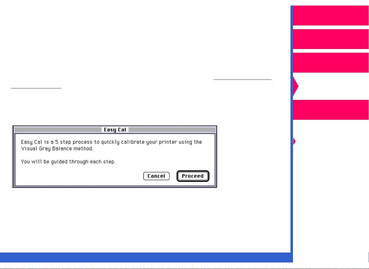
—a five-step process to quickly calibrate your printer using the
er to “Easy Cal” for instructions on
Printing
Guide
Color Management
Calibration
Network
Interface Guide
Getting Started
Easy Cal
Setting Preferences
and Using
Calibration Tables
Visual Gray Balance
Visual Linearity
Densitometer
Calibration
CONTENTS
INDEX
SEARCH
HELP
Page 5

Visual Gray Balance
neutral gray. Visual Gray Balance calibration ensures that the correct
percentages of cyan, magenta, and yellow dye are printed over the entire
tonal range to produce a neutral gray. Use the Visual Gray Balance
calibration if the color balance of your prints is not correct. Ref
“Visual Gray Balance” for instructions on running a Visual Gray Balance
calibration.
—calibrates your printer so that it produces a
er to
Operator’s Guide
Printing
Guide
Color Management
Visual Linearity
darkness. Visual Linearity ensures that your printer produces an accurate
representation of the requested density values over the entire tonal
range. Use the Visual Linearity calibration if the color balance is correct,
but the density is too dark or light. Ref
instructions on running a Visual Linearity calibration.
—calibrates your printer for the correct lightness/
er to “Visual Linearity” for
Densitometer Calibration
A densitometer calibration calibrates your printer’s response based on the
densitometer reading for selected patches on a test print. Calibrating your
printer with a densitometer yields the most accurate calibration results for
color balance and density. Ref
instructions on running a Densitometer calibration.
CONTENTS
INDEX
er to “Densitometer Calibration” for
SEARCH
HELP
Calibration
Network
Interface Guide
Getting Started
Easy Cal
Setting Preferences
and Using
Calibration Tables
Visual Gray Balance
Visual Linearity
Densitometer
Calibration
Page 6
Starting the Calibration Utility
Operator’s Guide
The following steps describe how to start the calibration utility:
NOTE: The illustrations in this chapter show Macintosh system dialog
boxes. The dialog boxes for Windows are similar and have
identical functionality.
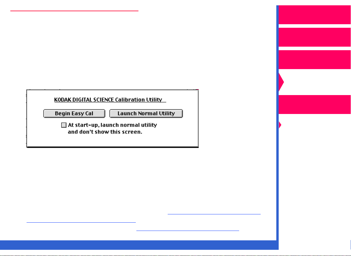
1.
Double-click on the icon for the calibration utility.
The calibration utility selection box opens.
2.
Do one of the following:
•
Click on
or
•
Click on
procedures.
Begin Easy Cal
Launch Normal Utility
to launch Easy Cal,
to use the other calibration
Printing
Guide
Color Management
Calibration
Network
Interface Guide
Getting Started
Easy Cal
Setting Preferences
and Using
Calibration Tables
Visual Gray Balance
Visual Linearity
Densitometer
Calibration
For infor mation about the Normal Utility, ref
Utility to Calibrate Your Printer.” For more infor mation on the
calibration utility selection box, ref
CONTENTS
INDEX
er to “Option Descriptions.”
SEARCH
er to “Using the Normal
HELP
Page 7

Using the Normal Utility to Calibrate Your Printer
Operator’s Guide
The Normal Utility allows you to create a new calibration document or
start from a previously-saved calibration document.
When you click on
selection box, the Normal Utility calibration procedure starts up; and the
Printer Calibration Utility window opens.
NOTE: If this is the first time you have run the calibration utility, or there
are no printers on the Select Printer menu, or the Preferences
files have been deleted, you must select and open the export
module.
For infor mation about creating a new calibration table, ref
“Creating a New Calibration Document.” For information about
opening an existing calibration document, ref
Calibration Table as the Star ting Point.”
Launch Normal Utility
in the Calibration Utility
er to
er to “Using an Existing
Printing
Guide
Color Management
Calibration
Network
Interface Guide
Getting Started
Easy Cal
Setting Preferences
and Using
Calibration Tables
Visual Gray Balance
Visual Linearity
Densitometer
Calibration
CONTENTS
INDEX
SEARCH
HELP
Page 8
Easy Cal
Operator’s Guide
Easy Cal provides you with the steps to guide you through the process of
calibrating your printer based on a Visual Gray Balance calibration.
NOTE: You cannot use Easy Cal to calibrate a printer with a black-only
ribbon.
For a description of the dialog boxes used in Easy Cal, ref
Descriptions.”
When you click on
dialog box, the Easy Cal calibration procedure starts up.
The Easy Cal dialog box appears.
•
Click on
Proceed
Begin Easy Cal
.
in the Calibration Utility selection
er to “Option
Printing
Guide
Color Management
Calibration
Network
Interface Guide
Getting Started
Easy Cal
Setting Preferences
and Using
Calibration Tables
Visual Gray Balance
Visual Linearity
Densitometer
Calibration
NOTE: Clicking on
CONTENTS
Cancel
INDEX
accesses the Normal Utility.
SEARCH
HELP
Page 9
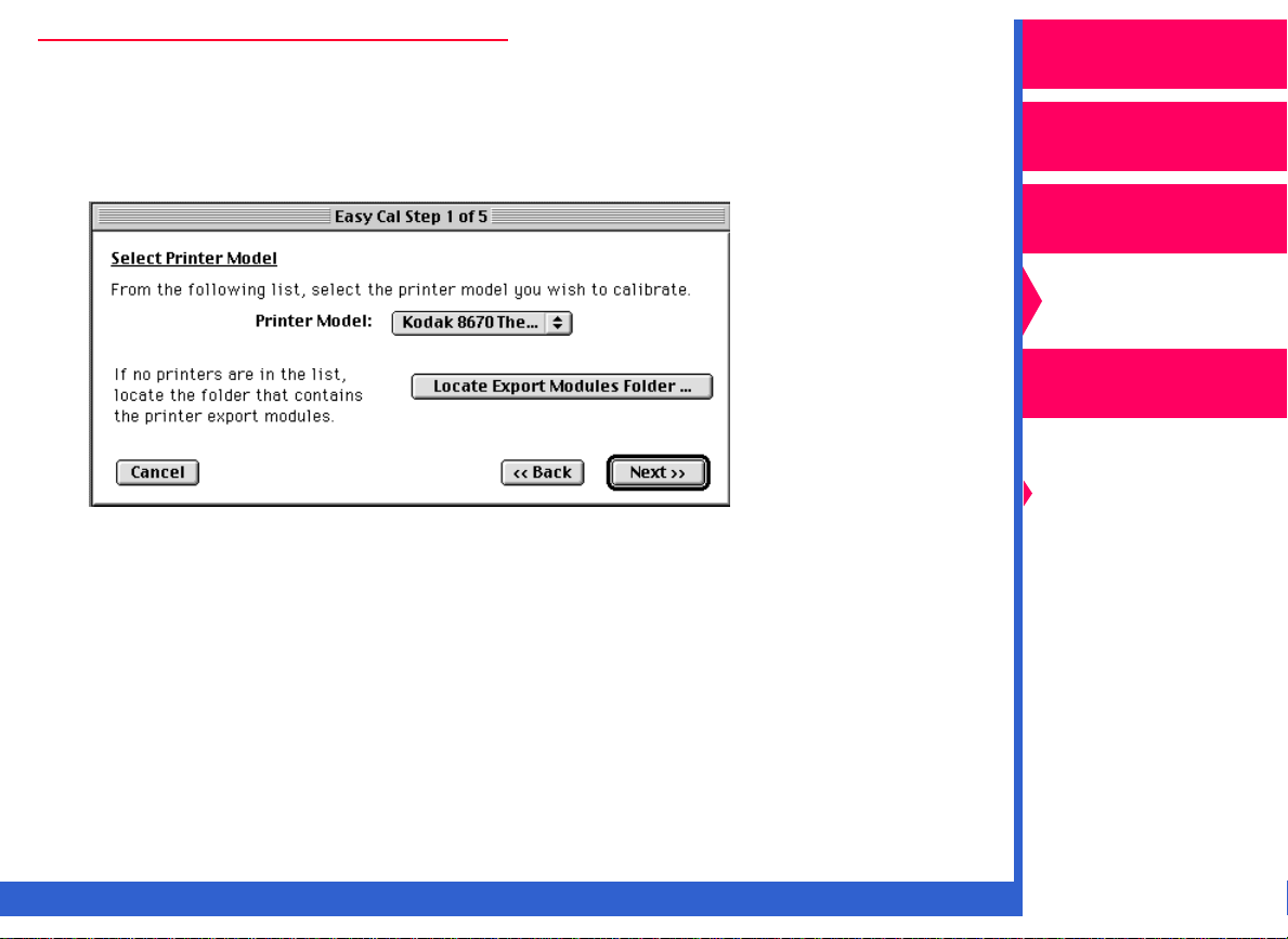
Easy Cal Step 1
Operator’s Guide
The Easy Cal Step1of 5 dialog box appears. This dialog box allows
you to select the printer model you wish to calibrate and locate the
folder containing the expor t module.
1.
Select the printer from the Printer Model drop-down list.
NOTE: If the printer you want to calibrate does not appear on the menu,
you must locate and select the expor t module for that printer.
2.
Click on
3.
In the file selection box that appears, locate and open the folder that
contains the export module:
Locate Export Modules Folder
.
Printing
Guide
Color Management
Calibration
Network
Interface Guide
Getting Started
Easy Cal
Setting Preferences
and Using
Calibration Tables
Visual Gray Balance
Visual Linearity
Densitometer
Calibration
•
On Macintosh systems, use the path System Folder:Applications
Support:Kodak:Plug-ins (Printing).
CONTENTS
INDEX
SEARCH
HELP
Page 10
•
On Windows systems, use the path C:\Windows\Kodak\Plugins
(Printing).
Operator’s Guide
4.
Select the export module, and click on
Easy Cal Step 1 of 5 dialog box.
5.
Click on
Next.
Open
. You are returned to the
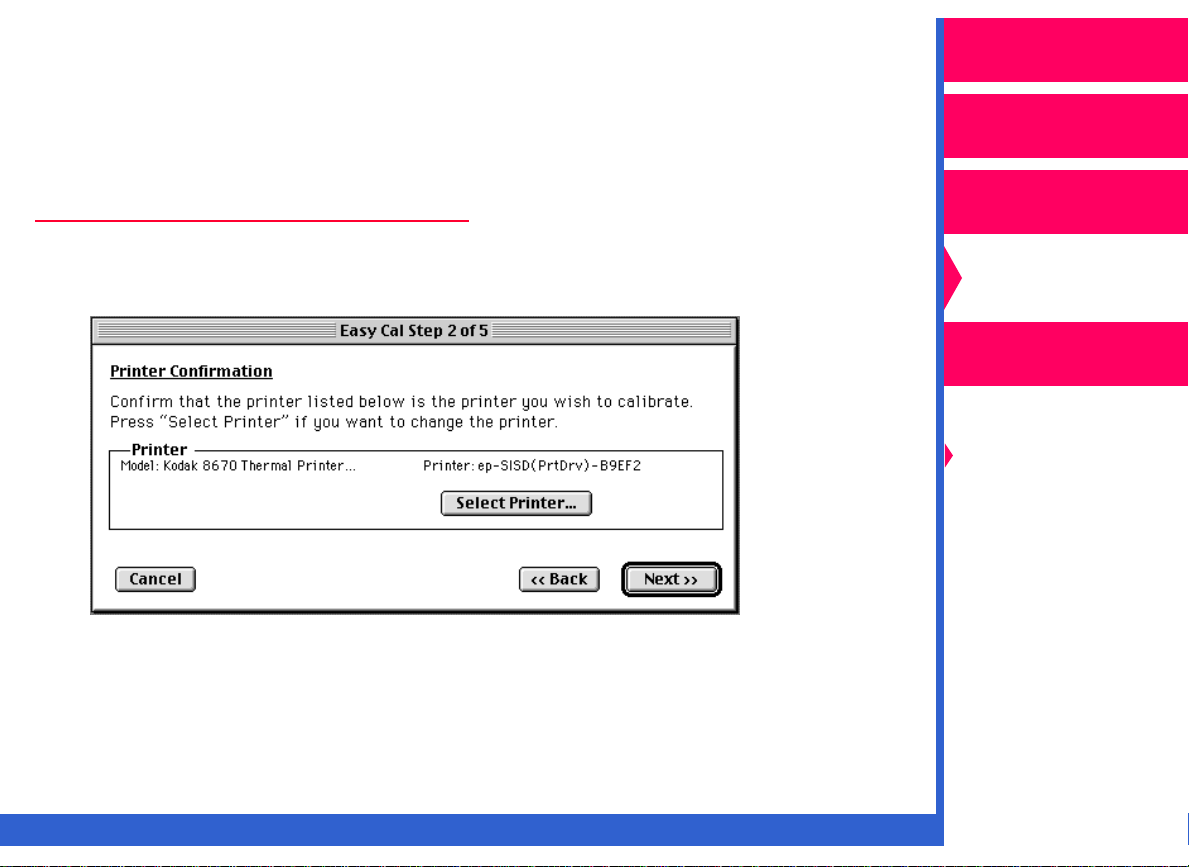
Easy Cal Step 2
The Easy Cal Step 2 of 5 dialog box appears.
1.
If you want to calibrate a different printer than the one that appears in
the Printer box, go to Step 2 in this procedure. If you do not need to
Next
select a new printer, click on
to go to Easy Cal Step 3 of 5.
Printing
Guide
Color Management
Calibration
Network
Interface Guide
Getting Started
Easy Cal
Setting Preferences
and Using
Calibration Tables
Visual Gray Balance
Visual Linearity
Densitometer
Calibration
2.
Click on
CONTENTS
Select Printer
INDEX
.
SEARCH
HELP
Page 11
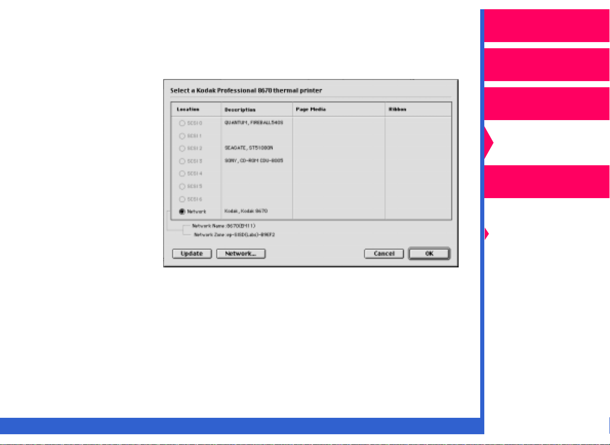
A dialog box appears that allows you to select the printer you wish to
calibrate.
Operator’s Guide
Macintosh systems
If the 8670 printer:
•
has a network
connection, click on
Network
in the
Select a Kodak
Professional 8670
thermal printer
dialog box.
In the selection box
that opens, choose
the correct 8670
OK
printer. Click on
to return to the
Select a Kodak
Professional 8670
thermal printer
dialog box.
•
has a SCSI connection, click on the radio button for the correct 8670
printer.
Printing
Guide
V1.0
Color Management
Calibration
Network
Interface Guide
Getting Started
Easy Cal
Setting Preferences
and Using
Calibration Tables
Visual Gray Balance
Visual Linearity
Densitometer
Calibration
CONTENTS
INDEX
SEARCH
HELP
Page 12
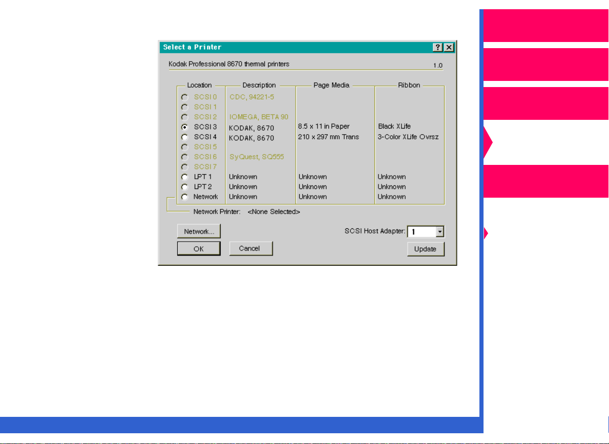
For Windows systems
If the 8670 printer:
•
has a SCSI
connection, click on
the radio button for
the correct 8670
printer.
•
has a network
connection, click on
Network
Browse
correct printer in
the Browse for
Printer dialog box
that opens.
•
has a parallel
connection, click on
the radio button for either LPT1 or LPT2 to select the printer.
Click on
NOTE: If your computer has more than one SCSI host adapter, pull down
.Click on
. Locate the
OK
in the Select a Printer dialog box.
the SCSI Host Adapter list. Select the por t address for the SCSI
host adapter for the selected 8670 printer.
Operator’s Guide
Printing
Guide
Color Management
Calibration
Network
Interface Guide
Getting Started
Easy Cal
Setting Preferences
and Using
Calibration Tables
Visual Gray Balance
Visual Linearity
Densitometer
Calibration
3.
Click on Next in the Easy Cal Step 2 of 5 dialog box.
CONTENTS
INDEX
SEARCH
HELP
Page 13
Easy Cal Step 3
Operator’s Guide
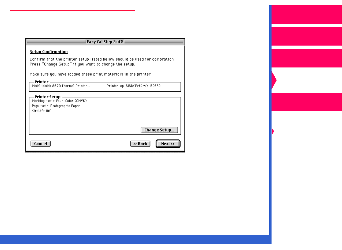
The Easy Cal Step 3 of 5 dialog box appears.
1.
Make sure that the ribbon and paper type information is correct.
NOTE: If you do not need to change the setup, click on
2.
Click on
Change Setup
.
Next
Printing
Guide
Color Management
Calibration
Network
Interface Guide
Getting Started
Easy Cal
Setting Preferences
and Using
Calibration Tables
Visual Gray Balance
.
Visual Linearity
Densitometer
Calibration
CONTENTS
INDEX
SEARCH
HELP
Page 14
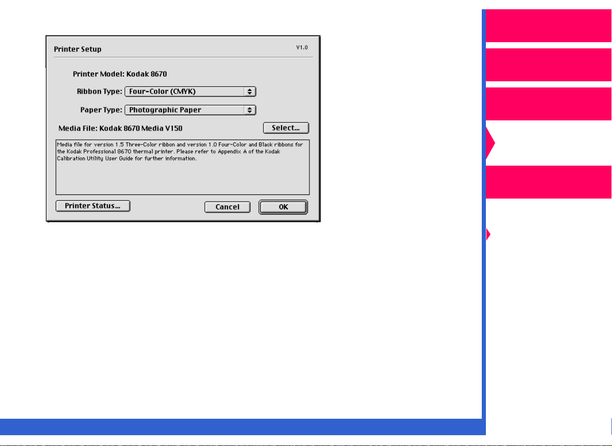
The Printer Setup for Calibration dialog box appears.
NOTE: Your Printer Setup dialog box may be different depending on your
printer export module.
3. Make the necessary changes in the Printer Setup dialog box.
OK
4. Click on
5. Click on
.
Next
in the Easy Cal Step 3 of 5 dialog box.
Operator’s Guide
Printing
Guide
Color Management
Calibration
Network
Interface Guide
Getting Started
Easy Cal
Setting Preferences
and Using
Calibration Tables
Visual Gray Balance
Visual Linearity
Densitometer
Calibration
CONTENTS
INDEX
SEARCH HELP
Page 15
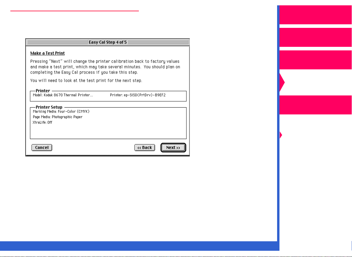
Easy Cal Step 4
Operator’s Guide
The Easy Cal Step 4of 5 dialog box appears.
.
1. Make sure that the Printer and Printer Setup information are correct.
IMPORTANT: Clicking on Next sends the default calibration table to the
printer and overwrites the previous table.
Printing
Guide
Color Management
Calibration
Network
Interface Guide
Getting Started
Easy Cal
Setting Preferences
and Using
Calibration Tables
Visual Gray Balance
Visual Linearity
Densitometer
Calibration
CONTENTS INDEX SEARCH HELP
Page 16
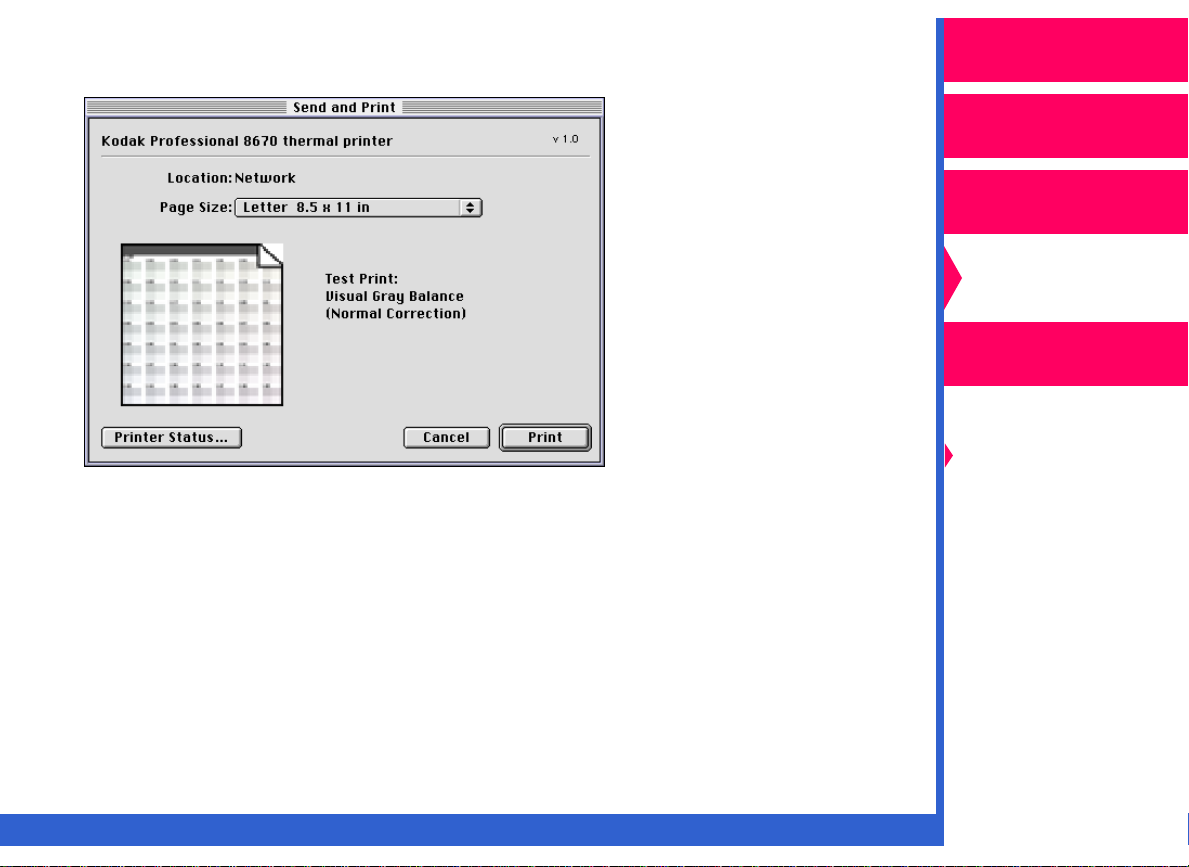
2. Click on
table is overwritten. The Send and Print dialog box appears.
NOTE: The Send and Print dialog box may be different depending on
3. Click on
The calibration test print is printed on the specified printer.
Next
. The default table is sent to the printer, and the previous
your printer’s export module.
Print
.
Operator’s Guide
Printing
Guide
Color Management
Calibration
Network
Interface Guide
Getting Started
Easy Cal
Setting Preferences
and Using
Calibration Tables
Visual Gray Balance
Visual Linearity
Densitometer
Calibration
CONTENTS INDEX SEARCH HELP
Page 17
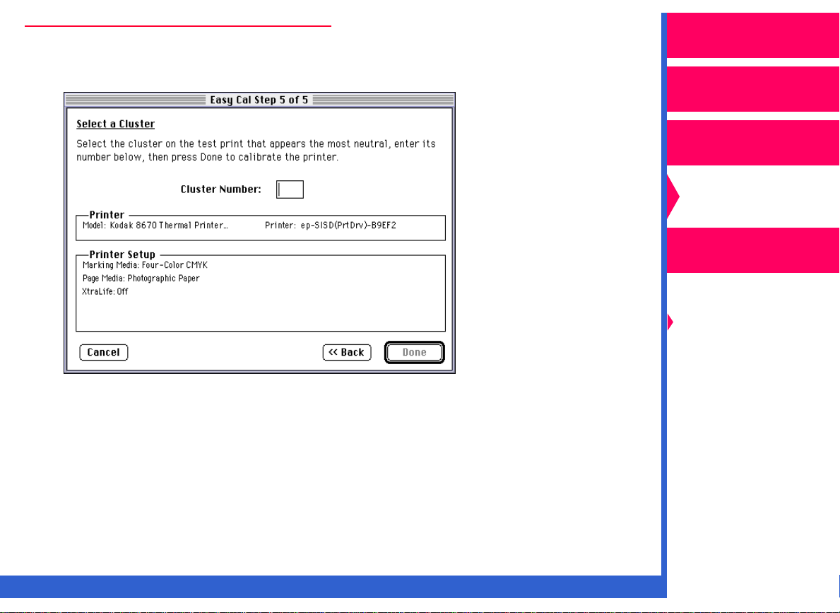
Easy Cal Step 5
Operator’s Guide
The Easy Cal Step 5 of 5 dialog box appears.
1. Use the test print to calibrate your printer in the Easy Cal Step 5 of 5
dialog box. Look at the test print, and decide which grayscale cluster
appears the most neutral gray.
Printing
Guide
Color Management
Calibration
Network
Interface Guide
Getting Started
Easy Cal
Setting Preferences
and Using
Calibration Tables
Visual Gray Balance
Visual Linearity
Densitometer
Calibration
CONTENTS INDEX SEARCH HELP
Page 18
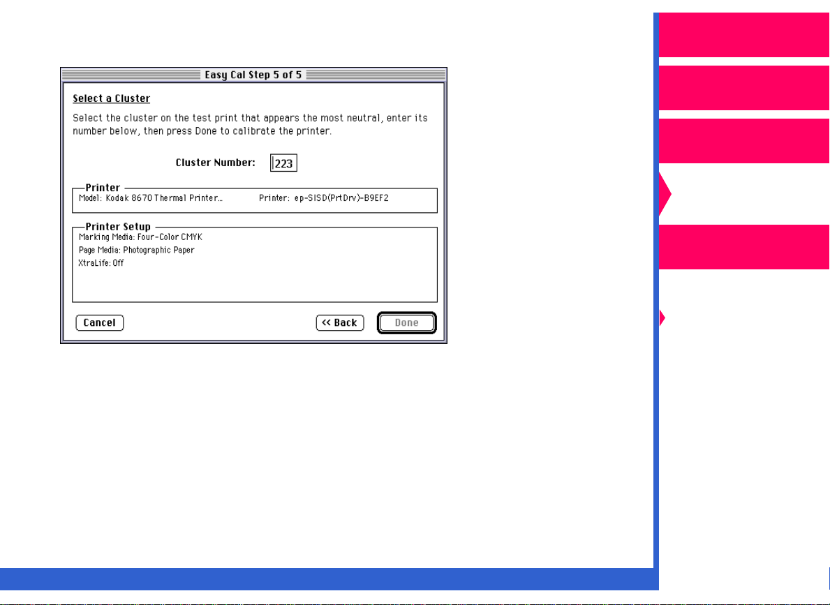
2. Enter the number of the most neutral grayscale cluster in the Cluster
Number text box.
NOTE: If you want to print an updated test print, you can click on
return to the Easy Cal Step 4 of 5 dialog box.
If cluster number 225 on the updated test print is the most neutral
gray, then the calibration is successful. Type 225 in the Cluster
Number text box, and go to Step 3 of this procedure.
Back
to
Operator’s Guide
Printing
Guide
Color Management
Calibration
Network
Interface Guide
Getting Started
Easy Cal
Setting Preferences
and Using
Calibration Tables
Visual Gray Balance
Visual Linearity
Densitometer
Calibration
3. Click on
CONTENTS INDEX SEARCH HELP
Done
.
Page 19
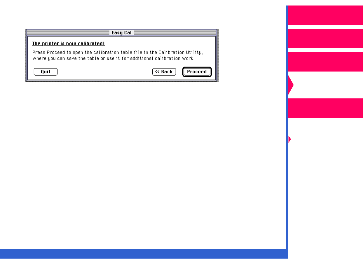
The printer calibration begins. When calibration completes, the Easy
Cal dialog box appears.
Quit
4. Click on
.
Operator’s Guide
Printing
Guide
Color Management
Calibration
Network
Interface Guide
Getting Started
Easy Cal
Setting Preferences
and Using
Calibration Tables
Visual Gray Balance
Visual Linearity
Densitometer
Calibration
CONTENTS INDEX SEARCH HELP
Page 20
Setting Preferences and Using Calibration
Operator’s Guide
Tables
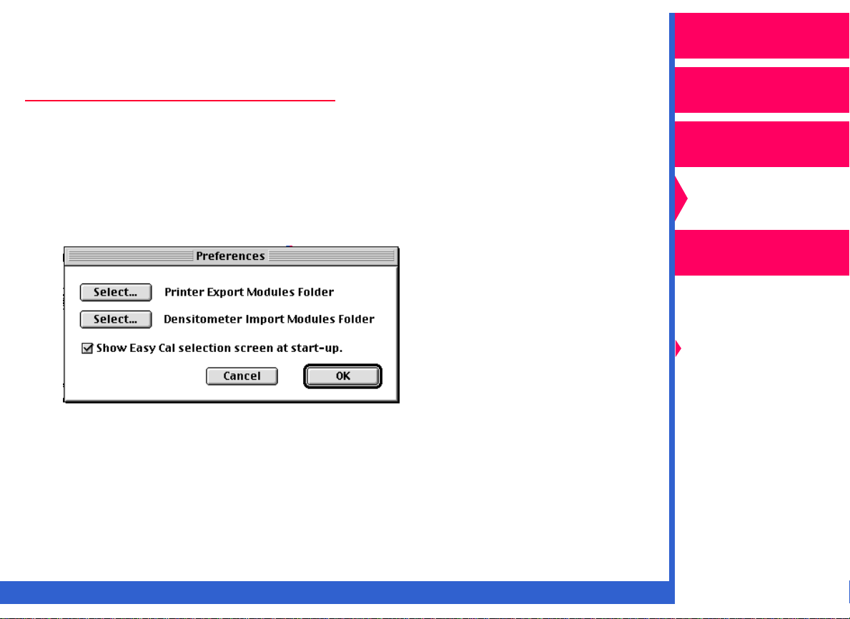
Using the Preferences Dialog Box
You can specify the folders that contain the export and import modules
(used for densitometer settings) in the Preferences dialog box.
1. Pull down the File menu, and select “Preferences”.
The Preferences dialog box appears.
2. Click on
the folders containing the expor t module and the impor t module.
Your selections are saved.
Select
, and use the file selection box that appears to locate
Printing
Guide
Color Management
Calibration
Network
Interface Guide
Getting Started
Easy Cal
Setting Preferences
and Using
Calibration Tables
Visual Gray Balance
Visual Linearity
Densitometer
Calibration
CONTENTS INDEX SEARCH HELP
Page 21
Selecting and Setting Up a Printer
Operator’s Guide
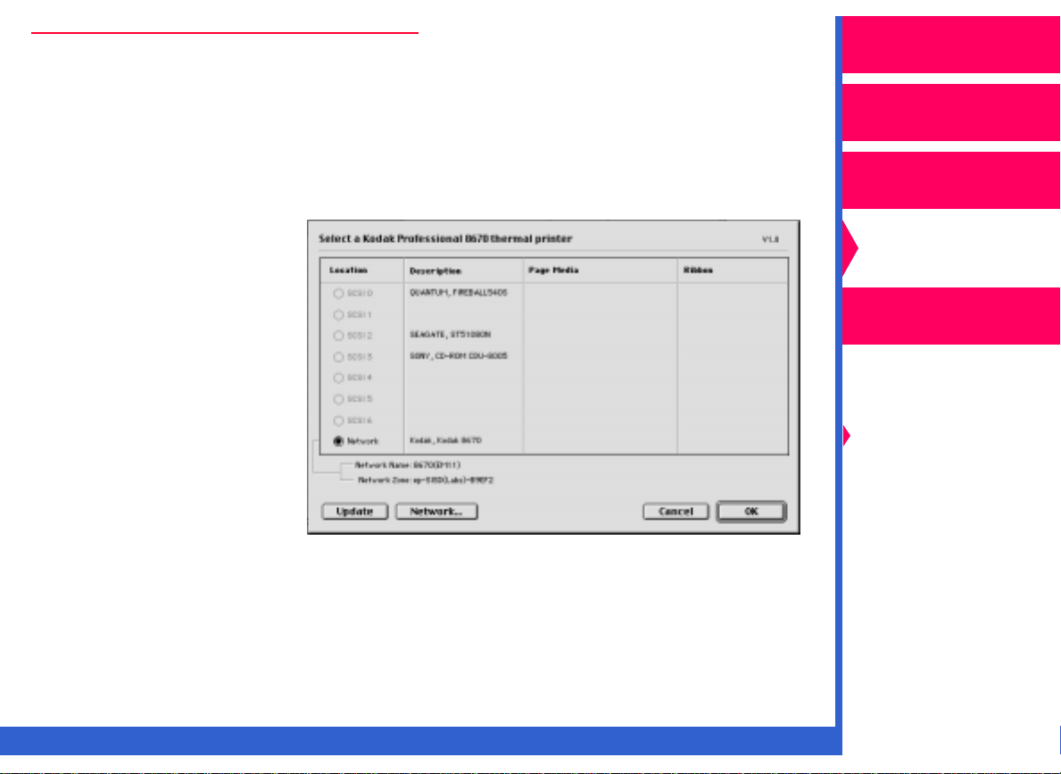
1. Pull down the Printer menu, and highlight “Select Printer”.
2. Select “8670 Thermal Printer”
Macintosh systems
If the 8670 printer:
• has a network
connection, click on
Network
a Kodak Professional
8670 thermal printer
dialog box.
In the selection box
that opens, chose the
correct 8670 printer.
Click on
to the Select a Kodak
Professional 8670
thermal printer dialog
box.
in the Select
OK
to return
Printing
Guide
Color Management
Calibration
Network
Interface Guide
Getting Started
Easy Cal
Setting Preferences
and Using
Calibration Tables
Visual Gray Balance
Visual Linearity
Densitometer
Calibration
• has a SCSI connection, click on the radio button for the correct 8670
printer.
CONTENTS INDEX SEARCH HELP
Page 22

For Windows systems
If the 8670 printer:
• has a SCSI
connection, click
on the radio
button for the
correct 8670
printer. Click on
OK
.
Operator’s Guide
Printing
Guide
Color Management
Calibration
• has a network
connection, click
Network
on
Browse
on
locate the correct
printer in the
Browse for Printer
dialog box that
opens. Click on
Select a Printer dialog box.Click on
• has a parallel connection, click on the radio button for LPT1 or LPT2.
Click on
NOTE: If your host computer has more than one SCSI host adapter
installed, pull down the SCSI Host Adapter list. Select the por t
address for the SCSI host adapter for the selected 8670 printer.
CONTENTS INDEX SEARCH HELP
, and
OK
.Click
OK
.
in the Network Printer dialog box to return to the
OK
again.
Network
Interface Guide
Getting Started
Easy Cal
Setting Preferences
and Using
Calibration Tables
Visual Gray Balance
Visual Linearity
Densitometer
Calibration
Page 23

3. Pull down the Printer menu, and select “Printer Setup”.
The Printer Setup dialog box appears.
NOTE: The configuration of the Printer Setup dialog box may be different
depending on the selected printer.
4. Select the ribbon and paper type for which you are calibrating.
OK
5. Click on
.
Operator’s Guide
Printing
Guide
Color Management
Calibration
Network
Interface Guide
Getting Started
Easy Cal
Setting Preferences
and Using
Calibration Tables
Visual Gray Balance
Visual Linearity
Densitometer
Calibration
CONTENTS INDEX SEARCH HELP
Page 24

Creating a New Calibration Document
Operator’s Guide
The following steps describe how to create a new calibration document to
use as a starting point for your calibration:
New
1. Pull down the File menu, and select
The Calibration Table dialog box appears.
.
Printing
Guide
Color Management
Calibration
Network
Interface Guide
Getting Started
Easy Cal
Setting Preferences
and Using
Calibration Tables
Visual Gray Balance
Visual Linearity
Densitometer
Calibration
NOTE: If the correct paper and ribbon do not appear, click on
Setup
Ref
CONTENTS INDEX SEARCH HELP
to change the paper and ribbon you wish to calibrate for.
er to “Selecting and Setting Up a Printer”.
Change
Page 25

2. Select a starting point for the calibration document:
Operator’s Guide
Read Current Table from Printer
•
the starting point.
NOTE: The “Read Current Table from Printer” starting point is not
available with Windows systems.
Use Printer’s Default Table
•
Copy Table from File
•
calibration table. Click on
appears which allows you to find and open the folder that contains
the calibration table you want to use as the star ting point.
NOTE: For more infor mation on the Calibration Table dialog box, ref
“Option Descr iptions.”
3. Click on OK.
—uses a previously-created and saved
Select File
—uses the printer’s current table as
—uses the printer’s default table.
, and a file selection dialog box
Printing
Guide
Color Management
Calibration
Network
Interface Guide
er to
Getting Started
Easy Cal
Setting Preferences
and Using
Calibration Tables
Visual Gray Balance
Visual Linearity
Densitometer
Calibration
CONTENTS INDEX SEARCH HELP
Page 26

A Calibration Document window appears.
4. Make sure that the information in the Printer Setup Information box is
correct and that you are creating a calibration table for the correct
ribbon and paper.
You can now calibrate your printer by running the Visual Gray
Balance and Visual Linearity calibration procedures.
Operator’s Guide
Printing
Guide
Color Management
Calibration
Network
Interface Guide
Getting Started
Easy Cal
Setting Preferences
and Using
Calibration Tables
Visual Gray Balance
Visual Linearity
Densitometer
Calibration
If you have a densitometer, you can run just the Densitometer
calibration procedure. You do not need to do Visual Gray Balance and
Visual Linearity calibrations.
CONTENTS INDEX SEARCH HELP
Page 27

NOTE: If you are using a black ribbon, you cannot use the Visual Gray
Balance calibration procedure. Go directly to the Visual Linearity
calibration procedure.
Using an Existing Calibration Table as the Starting Point
Follow the steps below only if you have previously created and saved a
calibration table. If the table you select as a starting point does not
contain printer setup information, ref
Printer.”
1. Select “Copy
Table from File” in
the Starting Point
box.
2. Click on
.
File
Select
er to “Selecting and Setting Up a
Operator’s Guide
Printing
Guide
Color Management
Calibration
Network
Interface Guide
Getting Started
Easy Cal
Setting Preferences
and Using
Calibration Tables
Visual Gray Balance
Visual Linearity
Densitometer
Calibration
CONTENTS INDEX SEARCH HELP
Page 28

An open file dialog box
appears.
Operator’s Guide
3. Find and open the folder
that contains the
calibration document you
want to use as the
starting point for your
new document.
NOTE: The data in the document selected as a starting point is specific
to the ribbon and paper selected when the document was
created.
4. Click on
Open.
Printing
Guide
Color Management
Calibration
Network
Interface Guide
Getting Started
Easy Cal
Setting Preferences
and Using
Calibration Tables
Visual Gray Balance
Visual Linearity
Densitometer
Calibration
CONTENTS INDEX SEARCH HELP
Page 29

The file selection dialog box closes. The selected calibration
document appears after the
5. Click on
OK
.
Copy Table from File
radio button.
Operator’s Guide
Printing
Guide
Color Management
Calibration
Network
Interface Guide
Getting Started
Easy Cal
Setting Preferences
and Using
Calibration Tables
Visual Gray Balance
Visual Linearity
Densitometer
Calibration
CONTENTS INDEX SEARCH HELP
Page 30

A Calibration Document window appears.
Opening an Existing Calibration Table
1. Pull down the File menu, and select “Open”.
2. Find and open the folder that contains the calibration table you want
to use in the file selection box that appears.
Operator’s Guide
Printing
Guide
Color Management
Calibration
Network
Interface Guide
Getting Started
Easy Cal
Setting Preferences
and Using
Calibration Tables
Visual Gray Balance
Visual Linearity
Densitometer
Calibration
3. Click on
A Calibration Document window appears.
CONTENTS INDEX SEARCH HELP
Open
.
Page 31

Using the Calibration Document Window
Operator’s Guide
Use the Calibration Document window to set up and run Visual Gray
Balance, Visual Linearity, and Densitometer calibrations.
1. Make sure that the information in the Printer Setup Information box is
correct and that you are creating a calibration table for the ribbon and
paper you want to use.
Printing
Guide
Color Management
Calibration
Network
Interface Guide
Getting Started
Easy Cal
Setting Preferences
and Using
Calibration Tables
Visual Gray Balance
Visual Linearity
Densitometer
Calibration
2. Enter the information for the printer you are calibrating in the Printer
Description text box.
CONTENTS INDEX SEARCH HELP
Page 32

3. Enter the information about the ribbon and paper you are calibrating
for in the Media Description text box.
Operator’s Guide
NOTE: Entries in the Printer Description and Media Descr iption text
boxes are optional and do not appear on the test print.
Calibrating Y our Printer
If you have a densitometer, you can run the Densitometer Calibration
procedure. If you run the Densitometer Calibration procedure, you do not
have to do Visual Gray Balance and Visual Linearity calibrations.
If you do not have a densitometer, you can calibrate your printer by
running the Visual Gray Balance or Visual Linearity Calibration
procedures.
Printing
Guide
Color Management
Calibration
Network
Interface Guide
Getting Started
Easy Cal
Setting Preferences
and Using
Calibration Tables
Visual Gray Balance
Visual Linearity
Densitometer
Calibration
CONTENTS INDEX SEARCH HELP
Page 33

Visual Gray Balance
Operator’s Guide
Visual Gray Balance calibrates your printer so that it produces a neutral
gray. The calibration utility allows you to select from three Visual Gray
Balance calibration prints. Each of these prints presents 49 numbered
grayscale clusters. Each cluster is made up of four boxes of varying
densities. A Visual Gray Balance calibration print looks similar to the
following example:
The clusters on the three prints include a range of colors. Clusters in the
upper left corner have a green hue. Clusters in the lower right corner have
a magenta hue. Three different calibration prints allow you to choose the
degree of color shift.
Printing
Guide
Color Management
Calibration
Network
Interface Guide
Getting Started
Easy Cal
Setting Preferences
and Using
Calibration Tables
Visual Gray Balance
Visual Linearity
Densitometer
Calibration
CONTENTS INDEX SEARCH HELP
Page 34

Fine—offers the least degree of difference between clusters. This print is
useful when it is difficult to choose between clusters on the normal
calibration print.
For example, you printed a normal pr int and find that the most neutrallooking clusters are next to each other, but one still looks slightly green
while the other still looks slightly magenta. You can print a fine calibration
print to get more choices within a smaller range of colors.
Operator’s Guide
Printing
Guide
Color Management
Normal—offers a moderate degree of difference between clusters. The
amount of correction in this print is appropriate for most calibration jobs.
Coarse—offers the greatest degree of difference in clusters. This print is
useful when neutral areas in prints appear very green or very magenta.
CONTENTS INDEX SEARCH HELP
Calibration
Network
Interface Guide
Getting Started
Easy Cal
Setting Preferences
and Using
Calibration Tables
Visual Gray Balance
Visual Linearity
Densitometer
Calibration
Page 35

Running a Visual Gray Balance Calibration
Operator’s Guide
1. Pull down the Calibration menu, and select “Visual Gray Balance” and
then “Setup Visual Gray Balance”.
The Calibration Setup—Visual Gray Balance dialog box appears.
NOTE: For a description of the dialog boxes used in the Visual Gray
Balance Calibration, ref
2. Select the amount of correction. Click on OK.
er to “Option Descriptions.”
Printing
Guide
Color Management
Calibration
Network
Interface Guide
Getting Started
Easy Cal
Setting Preferences
and Using
Calibration Tables
Visual Gray Balance
Visual Linearity
Densitometer
Calibration
CONTENTS INDEX SEARCH HELP
Page 36

You return to the Calibration Document window.
3. Click on
Send & Print
.
Operator’s Guide
Printing
Guide
Color Management
Calibration
Network
Interface Guide
Getting Started
Easy Cal
Setting Preferences
and Using
Calibration Tables
Visual Gray Balance
Visual Linearity
Densitometer
Calibration
CONTENTS INDEX SEARCH HELP
Page 37

The Send and Print dialog box appears.
NOTE: The Send and Print dialog box may be different depending on
your printer’s export module.
4. Click on
You return to the Calibration Document window. The calibration test
print is printed on the specified printer.
5. View the calibration test print, and determine which cluster appears
the most neutral.
Print
.
Operator’s Guide
Printing
Guide
Color Management
Calibration
Network
Interface Guide
Getting Started
Easy Cal
Setting Preferences
and Using
Calibration Tables
Visual Gray Balance
Visual Linearity
Densitometer
Calibration
CONTENTS INDEX SEARCH HELP
Page 38

If the number of the cluster that appears to be the most neutral ends
in 25, the printer is already calibrated. Do a Visual Linear ity
calibration. If the number of the most neutral cluster does not end in
25, recalibrate your printer to the most neutral cluster number.
Input
6. Click on
The Input Test Print Values dialog box appears.
7. Enter the number of the most neutral cluster in the box.
.
Operator’s Guide
Printing
Guide
Color Management
Calibration
Network
Interface Guide
Getting Started
Easy Cal
Setting Preferences
and Using
Calibration Tables
Visual Gray Balance
Visual Linearity
Densitometer
Calibration
CONTENTS INDEX SEARCH HELP
Page 39

NOTE: If you enter a value that ends in 25, the calibration table does not
change.
Operator’s Guide
8. Click on
The calibration table data is updated, and the Calibration Table
window appears.
9. Click on
the neutral in the cluster you selected, and you do not want to look at
another calibration print.
A confirmation box appears.
10. Click on
Recompute the Table
Send
in the Calibration Table window if you are satisfied with
Send
in the confirmation box.
.
Printing
Guide
Color Management
Calibration
Network
Interface Guide
Getting Started
Easy Cal
Setting Preferences
and Using
Calibration Tables
Visual Gray Balance
Visual Linearity
Densitometer
Calibration
CONTENTS INDEX SEARCH HELP
Page 40

The recomputed table is sent to the printer, and the following
message appears.
OK
11. Click on
.
Operator’s Guide
Printing
Guide
Color Management
Calibration
Network
Interface Guide
The calibration table is computed using the specified values, and you
return to the Calibration Document window. You should now perform a
Visual Linearity calibration.
NOTE: You should make another test print to verify your input value
adjustments.
CONTENTS INDEX SEARCH HELP
Getting Started
Easy Cal
Setting Preferences
and Using
Calibration Tables
Visual Gray Balance
Visual Linearity
Densitometer
Calibration
Page 41

Visual Linearity
Operator’s Guide
Visual Linearity calibrates your printer so that it produces the correct
density. Use the
Reference Card (reference card) included with the calibration utility to
select a cluster for each of the six density ranges. Visual Linearity
calibration prints look similar to the following examples.
NOTE: For best results, do a Visual Gray Balance calibration before you
start the Visual Linearity calibration.
Kodak Digital Science
Calibration Utility
Printing
Guide
Color Management
Calibration
Network
Interface Guide
Getting Started
Easy Cal
Setting Preferences
and Using
Calibration Tables
Visual Gray Balance
Visual Linearity
Densitometer
Calibration
CONTENTS INDEX SEARCH HELP
Page 42

Using the Reference Card
Operator’s Guide
Use the reference card which comes with your printer to
perform Visual Linearity calibrations. The following steps
describe how to use the reference card:
1. Lay the reference card with the name at the top on the
first row of the calibration test print.
2. Slide the reference card across each path in the row,
and determine which of the nine patches in the row
most closely matches the darkness on the reference
card.
NOTE: It may not be possible to find a cluster in which all
six gray levels exactly match the reference card. Select the
cluster that is the closest match. Match the darkness on the
reference card and not the color.
3. Repeat Step 2 for each row on the calibration print.
Printing
Guide
Color Management
Calibration
Network
Interface Guide
Getting Started
Easy Cal
Setting Preferences
and Using
Calibration Tables
Visual Gray Balance
Visual Linearity
Densitometer
Calibration
CONTENTS INDEX SEARCH HELP
Page 43

Running a Visual Linearity Calibration
Operator’s Guide
After you have run a Visual Gray Balance calibration, run the Visual
Linearity calibration to recompute the current calibration table using
values from the test print.
1. Pull down the Calibration menu, and select “Visual Linearity”.
You return to the Calibration Document window.
Printing
Guide
Color Management
Calibration
Network
Interface Guide
Getting Started
Easy Cal
Setting Preferences
and Using
Calibration Tables
Visual Gray Balance
Visual Linearity
Densitometer
Calibration
2. Click on
CONTENTS INDEX SEARCH HELP
Send & Print
.
Page 44

The Send and Print dialog box appears.
NOTE: Your Send and Print dialog box may be different depending on
your printer’s export module.
For a description of the dialog boxes used in the Visual Linearity
Calibration, ref
3. Click on
You return to the Calibration Document window. The calibration test
print is printed on the specified printer.
Print
.
er to “Option Descriptions.”
Operator’s Guide
Printing
Guide
Color Management
Calibration
Network
Interface Guide
Getting Started
Easy Cal
Setting Preferences
and Using
Calibration Tables
Visual Gray Balance
Visual Linearity
Densitometer
Calibration
4. Click on Input in the Calibration Document window,
CONTENTS INDEX SEARCH HELP
Page 45

The Input Test Print Values dialog box appears.
One, three, or four density value columns appear in the Input Test
Print Values dialog box depending upon the ribbon that is in the
printer.
5. Use the calibration utility reference card to select a box number.
If all of the Visual Linearity numbers on the test print are box number
5, the printer is already calibrated. If the Visual Linear ity numbers on
the test print are not all box number 5, you must recalibrate the
printer. Go to Step 6.
Operator’s Guide
Printing
Guide
Color Management
Calibration
Network
Interface Guide
Getting Started
Easy Cal
Setting Preferences
and Using
Calibration Tables
Visual Gray Balance
Visual Linearity
Densitometer
Calibration
6. Type in the values you selected from the test print in the text boxes.
Click on
CONTENTS INDEX SEARCH HELP
Recompute the Table
button.
Page 46

The calibration table is computed using the specified values, and the
Calibration window appears.
Send
7. Click on
to send the table to the printer.
Operator’s Guide
Printing
Guide
Color Management
Calibration
Network
Interface Guide
Getting Started
Easy Cal
Setting Preferences
and Using
Calibration Tables
Visual Gray Balance
Visual Linearity
Densitometer
Calibration
CONTENTS INDEX SEARCH HELP
Page 47

Densitometer Calibration
Operator’s Guide
The Densitometer Calibration corrects the printer’s response based on a
densitometer reading for selected patches on a test print. If you have a
densitometer, you do not need to run Visual Gray Balance and Visual
Linearity calibrations. You only need to do a Densitometer Calibration.
With the Densitometer Calibration procedure, you make a test print and
measure the density values for each of the patches on the test print with
the densitometer. You then enter the density results for each of the
patches in the Densitometer Input Test Print Values dialog box.
The printer can print either a 15 or a 38-step test print. Using the 38-step
target yields the best calibration results; however, calibration time is
increased if you use a manual densitometer. The Densitometer
Calibration test prints look similar to the following examples depending on
the media you are calibrating for :
Printing
Guide
Color Management
Calibration
Network
Interface Guide
Getting Started
Easy Cal
Setting Preferences
and Using
Calibration Tables
Visual Gray Balance
Visual Linearity
Densitometer
Calibration
CMY
CONTENTS INDEX SEARCH HELP
K
CMYK
Page 48

Running a Densitometer Calibration
Operator’s Guide
1. Make sure your densitometer is calibrated and set up according to
the manufacturer’s instructions.
2. Pull down the Calibration menu, and select “Densitometer”.
3. Pull down the Calibration menu, and select “Setup Densitometer”.
The Calibration Setup — Densitometer dialog box appears.
NOTE: For a description of the dialog boxes used in the Densitometer
Calibration, ref
4. Select a densitometer status in the Densitometer box.
5. Pull down the Number of Squares menu in the test Print box, and
select the number of squares you want in your test print.
er to “Option Descriptions.”
Printing
Guide
Color Management
Calibration
Network
Interface Guide
Getting Started
Easy Cal
Setting Preferences
and Using
Calibration Tables
Visual Gray Balance
Visual Linearity
Densitometer
Calibration
OK
6. Click on
CONTENTS INDEX SEARCH HELP
.
Page 49

The Calibration Document window appears.
7. Click on
Send & Print
.
Operator’s Guide
Printing
Guide
Color Management
Calibration
Network
Interface Guide
Getting Started
Easy Cal
Setting Preferences
and Using
Calibration Tables
Visual Gray Balance
Visual Linearity
Densitometer
Calibration
CONTENTS INDEX SEARCH HELP
Page 50

The Send and Print dialog box appears.
NOTE: Your Send and Print dialog box may be different depending on
your printer’s export module.
Print
Input
.
.
8. Click on
You return to the Calibration Document window. The specified printer
prints the test print.
9. Click on
Operator’s Guide
Printing
Guide
Color Management
Calibration
Network
Interface Guide
Getting Started
Easy Cal
Setting Preferences
and Using
Calibration Tables
Visual Gray Balance
Visual Linearity
Densitometer
Calibration
CONTENTS INDEX SEARCH HELP
Page 51

The Input Test Print Values dialog box appears.
One, three, or four density value columns appear depending upon the
ribbon that is in the printer.
For manual densitometers only, valid characters in this dialog box
include numbers from 0 to 9 and decimal points. The valid range is 0
to 3.000. Move from cell to cell using the arrow keys. You can copy
and paste any group of contiguous fields in a rectangular pattern.
Operator’s Guide
Printing
Guide
Color Management
Calibration
Network
Interface Guide
Getting Started
Easy Cal
Setting Preferences
and Using
Calibration Tables
Visual Gray Balance
Visual Linearity
Densitometer
Calibration
10. Type the test print values in the text boxes in the Input Test Print
Values dialog box.
CONTENTS INDEX SEARCH HELP
Page 52

NOTE: You can impor t data from a densitometer automatically with an
import module. If your densitometer has an associated import
module, the densitometer readings are imported directly into the
dialog box. If your densitometer does not have an import module,
er to “Using the Kodak Digital Science File Reader.”
ref
11. Click on
The calibration table is computed using the specified values, and the
Calibration Document window appears.
Recompute the Table
.
Operator’s Guide
Printing
Guide
Color Management
Calibration
Network
Interface Guide
Getting Started
Easy Cal
Setting Preferences
and Using
Calibration Tables
Visual Gray Balance
Visual Linearity
Densitometer
Calibration
CONTENTS INDEX SEARCH HELP
Page 53

Option Descriptions
Operator’s Guide
This section describes the calibration utility menus and dialog box
options.
File Menu
This section describes the options on the File pulldown menu.
New—accesses the Calibration Document window so that you can select
options for the current printer setup.
Open—accesses a file open dialog box so you can select an existing
calibration table from which to start.
Close—closes the current calibration document.
Printing
Guide
Color Management
Calibration
Network
Interface Guide
Getting Started
Easy Cal
Setting Preferences
and Using
Calibration Tables
Visual Gray Balance
Visual Linearity
Densitometer
Calibration
CONTENTS INDEX SEARCH HELP
Page 54

Save—saves changes to the current calibration document. When you
name a calibration document, you may want to include characters that
indicate the selected paper types. Saving a document in this way allows
you to select it later to use as a starting point for a new calibration
document.
Save As—accesses a dialog box in which you can specify a new name
and location for the current calibration settings. When you name a
calibration document, you may want to include characters that indicate
the selected paper type. Naming a document in this way allows you to
select it later to use as a starting point for a calibration document.
Revert—returns a calibration document to its original state. All
recomputations are discarded.
Operator’s Guide
Printing
Guide
Color Management
Calibration
Network
Interface Guide
Preferences—accesses a dialog box that allows you to specify the folder
containing the export module and the folder containing the import
modules.
CONTENTS INDEX SEARCH HELP
Getting Started
Easy Cal
Setting Preferences
and Using
Calibration Tables
Visual Gray Balance
Visual Linearity
Densitometer
Calibration
Page 55

Use the following default paths for locating the folder containing the
export module:
Operator’s Guide
• On Macintosh systems—System Folder:Applications
Support:Kodak:Plug-ins (Printing).
• On Windows systems— C:\Windows\Kodak\Plug-ins (Printing)
Use the following default paths for locating the folder containing the
import modules:
• On Macintosh systems— Kodak DS Calibration Utility:Densitometer
Import Modules
• On Windows systems—C:\Kodakcal\Densitom
Quit—exits the Calibration Utility.
Printing
Guide
Color Management
Calibration
Network
Interface Guide
Getting Started
Easy Cal
Setting Preferences
and Using
Calibration Tables
Visual Gray Balance
Visual Linearity
Densitometer
Calibration
CONTENTS INDEX SEARCH HELP
Page 56

Edit Menu
Operator’s Guide
The Edit menu is enabled only when the Calibration Table window is open.
NOTE: The options in the Edit menu are enabled only when you enter
text in the Printer Description and Media Description boxes.
Calibration Menu
The Calibration menu is enabled when the Calibration Table window is
open. You can choose to calibrate based on your input to the Visual Gray
Balance, Visual Linearity, and Densitometer dialog boxes.
Printing
Guide
Color Management
Calibration
Network
Interface Guide
Getting Started
Easy Cal
Setting Preferences
and Using
Calibration Tables
Visual Gray Balance
Visual Linearity
Densitometer
Calibration
CONTENTS INDEX SEARCH HELP
Page 57

Calibration Setup — Visual Gray Balance
This dialog box allows you to specify the degree of correction to apply
with the current calibration table.
Operator’s Guide
Printing
Guide
Color Management
Calibration
Network
Interface Guide
Amount of Correction
Amount of Correction
The
difference between the neutrals in the calibration print:
Fine—the calibration print offers the least degree of difference in neutrals
between the cluster in the upper left corner and the cluster in the lower
right corner. The cluster in the upper left corner is only slightly green and
the cluster in the lower right corner is only slightly magenta.
Select Fine to get the smallest hue range. The hue differences between
clusters will be small so that you can fine-tune by choosing between
similar neutrals.
CONTENTS INDEX SEARCH HELP
buttons allow you to specify what degree of
Getting Started
Easy Cal
Setting Preferences
and Using
Calibration Tables
Visual Gray Balance
Visual Linearity
Densitometer
Calibration
Page 58

Normal—the calibration print offers a moderate degree of difference in
neutrals between the cluster in the upper left corner and the cluster in the
lower right corner. The cluster in the upper left corner is somewhat green
and the cluster in the lower right corner is somewhat magenta.
Select Normal to get a larger hue range than “Fine.” This means that the
hue differences between clusters are slightly larger and that adjacent
clusters are less similar.
Operator’s Guide
Printing
Guide
Color Management
Coarse—the calibration print offers the greatest degree of difference in
neutrals between the cluster in the upper left corner and the cluster in the
lower right corner. The cluster in the upper left corner is distinctly green,
and the cluster in the lower right corner is distinctly magenta.
Select Coarse to get the largest hue range. This means that the hue
differences between clusters are easily discernible and adjacent clusters
are distinctly different.
CONTENTS INDEX SEARCH HELP
Calibration
Network
Interface Guide
Getting Started
Easy Cal
Setting Preferences
and Using
Calibration Tables
Visual Gray Balance
Visual Linearity
Densitometer
Calibration
Page 59

Calibration Setup—Densitometer
NOTE: Make sure that your densitometer is calibrated before you try to
calibrate your printer with the densitometer values.
Operator’s Guide
Printing
Guide
Color Management
Calibration
Network
Interface Guide
Densitometer—This setting allows you to specify what type of density
data (Status A or Status T) your densitometer provides. The Calibration
Utility calculates the table data using the density type that the export
module needs for the current calibration slot.
Test Print — Number of Squares
The Number of Squares menu in the Test Print box allows you to specify
the number of squares (15 or 38) in your test print.
CONTENTS INDEX SEARCH HELP
Getting Started
Easy Cal
Setting Preferences
and Using
Calibration Tables
Visual Gray Balance
Visual Linearity
Densitometer
Calibration
Page 60

Printer Menu
Operator’s Guide
The Printer menu allows you to select a printer or set up the printer from
the menu bar.
Select Printer—a menu with the printer types that you can select from
appears. Selecting a printer type opens a dialog box that allows you to
choose the specific printer you wish to calibrate.
Printer Setup—the Printer Setup for Calibration dialog box appears so
that you can select the ribbon and paper installed in the printer.
Easy-Cal Menu
The Easy-Cal menu allows you to start the Easy Cal calibration procedure
from the menu bar.
Begin—the Easy Cal calibration procedure starts up.
Printing
Guide
Color Management
Calibration
Network
Interface Guide
Getting Started
Easy Cal
Setting Preferences
and Using
Calibration Tables
Visual Gray Balance
Visual Linearity
Densitometer
Calibration
Begin with Previous Settings—the Easy Cal Step 4 dialog box appears.
CONTENTS INDEX SEARCH HELP
Page 61

KODAK DIGITAL SCIENCE Calibration Utility Dialog Box
Operator’s Guide
When you launch the Calibration Utility for the first time, the Calibration
Utility dialog box appears.
You can click on
Launch Normal Utility
or Densitometer calibration procedures.
NOTE: If you want to go directly to the Normal Utility without this dialog
box opening each time you start the Calibration Utility, select “At
start-up launch nor mal utility and don’t show this screen”.
To use Easy Cal from within the Nor mal Utility, pull down the Easy-Cal
menu, and select “Begin” or “Begin with Previous Settings”.
Begin Easy Cal
to go to the Visual Gray Balance, Visual Linearity,
to start up Easy Cal, or you can click on
Printing
Guide
Color Management
Calibration
Network
Interface Guide
Getting Started
Easy Cal
Setting Preferences
and Using
Calibration Tables
Visual Gray Balance
Visual Linearity
Densitometer
Calibration
CONTENTS INDEX SEARCH HELP
Page 62

Calibration Table Dialog Box
Operator’s Guide
Pull down the File menu and select ”New” to access a dialog box that
allows you to create a new calibration table.
Printer Setup
The Printer Setup box lists information about the ribbon and paper type
for which the printer will be calibrated.
Printing
Guide
Color Management
Calibration
Network
Interface Guide
Getting Started
Easy Cal
Setting Preferences
and Using
Calibration Tables
Visual Gray Balance
Visual Linearity
Densitometer
Calibration
CONTENTS INDEX SEARCH HELP
Page 63

Click on Change Setup to change the ribbon and paper settings.
Change Setup—accesses the Printer Setup for Calibration dialog box so
that you can select options that match the paper in the printer you are
calibrating.
Operator’s Guide
Printing
Guide
Color Management
Calibration
Network
Interface Guide
Getting Started
Easy Cal
Setting Preferences
and Using
Calibration Tables
Visual Gray Balance
Visual Linearity
Densitometer
Calibration
CONTENTS INDEX SEARCH HELP
Page 64

Starting Point
The Starting Point box allows you to select the data that will act as a base
for the new calibration table.
Operator’s Guide
Printing
Guide
Color Management
Calibration
Read Current Table From Printer—allows you to retrieve and begin with
the table currently in the printer. After the table is loaded, you can edit it
and recalibrate the printer. This option is not always available as a
starting point.
NOTE: The Read Current Table From Printer is not available if the printer
cannot return this information. For example, many printers with a
parallel connection have this item deselected.
Use Printer’s Default Table—default data in the printer acts as the
starting point for the new calibration document.
Copy Table from File—the calibration table you select with the Select
File button acts as the starting point for the new calibration document.
CONTENTS INDEX SEARCH HELP
Network
Interface Guide
Getting Started
Easy Cal
Setting Preferences
and Using
Calibration Tables
Visual Gray Balance
Visual Linearity
Densitometer
Calibration
Page 65

Select File—opens a file open box so you can choose an existing
calibration document from which to start.
Operator’s Guide
Printing
Guide
Color Management
Calibration
OK
OK
The
window. Refer to Ref
information.
Cancel
The
calibration document.
CONTENTS INDEX SEARCH HELP
button closes the dialog box and opens the Calibration Table
er to “Calibration Document Window” for more
Cancel
button closes the dialog box without creating a new
Network
Interface Guide
Getting Started
Easy Cal
Setting Preferences
and Using
Calibration Tables
Visual Gray Balance
Visual Linearity
Densitometer
Calibration
Page 66

Calibration Document Window
Operator’s Guide
The Calibration Document window allows you to specify information about
the calibration table.
Printer Description
The Printer Description text box allows you to enter information that
describes the printer you are calibrating. The text you enter is used to
describe the specifics of a particular calibration table. This text is not
printed on the test print. An entry is optional.
Printing
Guide
Color Management
Calibration
Network
Interface Guide
Getting Started
Easy Cal
Setting Preferences
and Using
Calibration Tables
Visual Gray Balance
Visual Linearity
Densitometer
Calibration
CONTENTS INDEX SEARCH HELP
Page 67

Media Description
The Media Description text box allows you to enter information that
describes the paper and the ribbon for which the calibration table will be
used. The text you enter is used to help describe the specifics of a
particular calibration table. This text is not printed on the test print. An
entry is optional.
Calibration T ools
Operator’s Guide
Printing
Guide
Color Management
Calibration Tools offers handling options for the calibration table.
Send & Print—sends the current calibration table to the printer. A
calibration print is generated so you can evaluate the results.
Input—accesses the Input Test Print Values dialog box so you can enter
visual gray balance, visual linearity, and densitometer data.
Send—sends the current calibration table to the printer without
generating a calibration print. This button is usually used after you have
created a test print and recomputed the calibration table.
CONTENTS INDEX SEARCH HELP
Calibration
Network
Interface Guide
Getting Started
Easy Cal
Setting Preferences
and Using
Calibration Tables
Visual Gray Balance
Visual Linearity
Densitometer
Calibration
Page 68

Using the Kodak Digital Science File Reader
Operator’s Guide
The calibration utility includes the
that you can import data into the Input Test Print Values screen from a
densitometer. To use the file reader, you need the following software:
• a utility to capture the values from the densitometer. If software is not
provided with your densitometer, you may use a terminal program.
NOTE: The values from the densitometer should have no more than 3
decimal places.
• an application such as Microsoft Excel or SimpleText to save the data
as a text file.
The following steps describe how to use the file reader:
1. Create a document to capture the data from the densitometer. Be
sure to save the document as a text file.
2. Select "Kodak File Reader" from the Import Modules menu.
3. Click on
Import
.
Kodak Digital Science
file reader so
Printing
Guide
Color Management
Calibration
Network
Interface Guide
Getting Started
Easy Cal
Setting Preferences
and Using
Calibration Tables
Visual Gray Balance
Visual Linearity
Densitometer
Calibration
CONTENTS INDEX SEARCH HELP
Page 69

The Kodak Digital Science File Reader dialog box opens.
Operator’s Guide
Printing
Guide
Color Management
Calibration
4. Specify the end-of-field character used in your densitometer file:
“space,” “comma,” “tab,” “CR” (carriage return), “CR-LF” (carriage
return/line feed), “LF” (line feed), and “Semi-colon.”
5. Specify the end-of-record character used in your densitometer file:
“space,” “comma,” “tab,” “CR” (carriage return), “CR-LF” (carriage
return/line feed), “LF” (line feed), and “Semi-colon.”
6. Click on
data from your densitometer. When the file opens, the data will be
imported into the Input Test Print Values window.
7. Complete the Densitometer Calibration procedure. Ref
a Densitometer Calibration”.
CONTENTS INDEX SEARCH HELP
Open
. Locate the document you wish to use to capture the
er to “Running
Network
Interface Guide
Getting Started
Easy Cal
Setting Preferences
and Using
Calibration Tables
Visual Gray Balance
Visual Linearity
Densitometer
Calibration
 Loading...