

Page 1
T
T
e
e
c
c
h
h
nii
n
c
c
all
a
Trr
T
aii
a
nii
n
n
n
g
g
G
Pre-site Inspection……………………… Page 2
Printer Features………………………… Page 4
Printer Installation…………………....... Page 7
Printer Calibrations……………………………… Page 14
Networking………………………………………. Page 18
Print Mode/Dryer Guidelines…………………... Page 23
G
uii
u
d
d
e
e
Printer Operation Tips…………………. Page 27
Software Control Tips…………………. Page 30
Printer Maintenance…………………. Page 31
Bulletin Reference List………………… Page 40
Error Message Codes…………………. Page 41
Printer Grounding/Static Control……. Page 65
Technical Training Guide
Page 2
KODAK 1200i WIDE-FORMAT PRINTING SYSTEM
PPrreessiittee IInnssppeeccttiioonn
Installation Requirements
The Kodak 1200i wide-format printing system requires approximately 15’ x 20’ (4 x 6
meters) square space available for the printer un-boxing and setup. Additionally, vice
grips/pliers may be needed to aid in support bracket removal. Four (4) people will need
to be available to assist in the setup.
((pprree--iinnssttaallllaattiioonn)
)
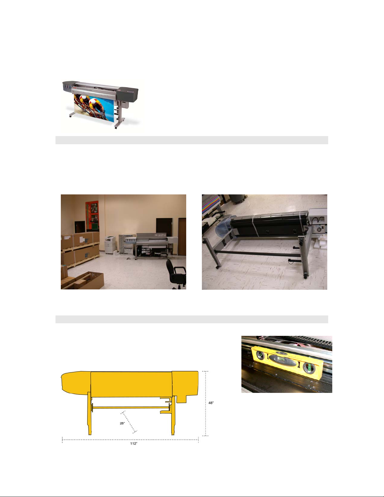
Operational Space Requirements
Ensure printer is placed onto a level floor surface – use a
fluid level to verify printer is properly leveled.
Printer footprint dimensions are illustrated below:
Technical Training Guide 2
Page 3
KODAK 1200i WIDE-FORMAT PRINTING SYSTEM
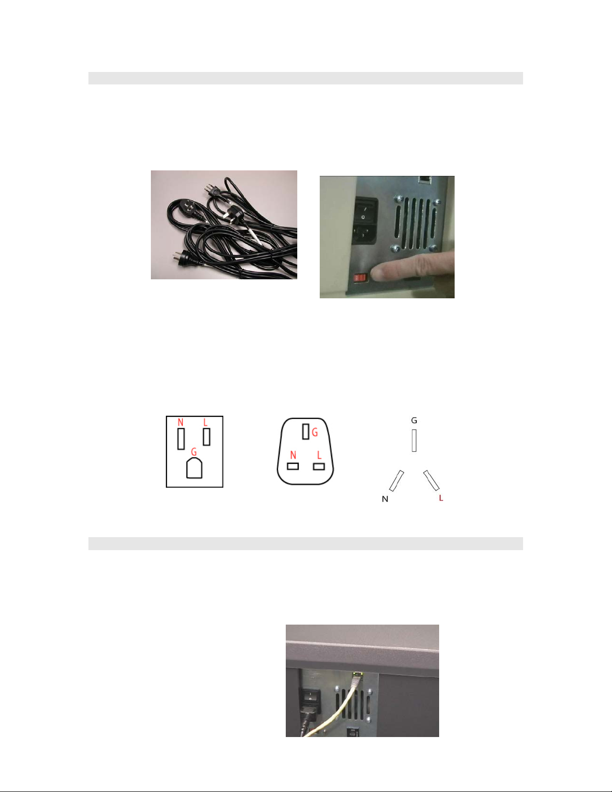
Power Requirements
Either 115 or 230 volt, 50/60Hz source power is required for the printer. All major power
cord standards are supplied with each printer. The voltage selector switch is positioned
to the 230 volt position during shipping; ensure selector switch is set to either 115 or 230
for the appropriate region. The printer typically uses 1100 watts of power during normal
operation (when dryer is engaged) –a dedicated 20 amp circuit is ideal.
NOTE: The printer must be properly grounded in accordance with regional and general
equipment/electrical grounding guidelines or improper print operation may result and
personnel hazards may result if inadequate grounding is provided. Verify a ground line
(G) is present at power receptacle or power strip prior to installing the printer, refer to
receptacle examples below.
US/Canada
UK/Singapore/
Hong Kong
China
Connectivity Requirements
The printer can be connected directly to a computer via an Ethernet crossover cable or
via a regular Ethernet cable (RJ-45) connected to a 100BaseT HUB/Switch/Router
placed on the network. For DHCP (Dynamic Host Control Protocol) networks a static IP
address (dedicated address for printer) must be made available; consult a network
administrator to verify system setup.
Technical Training Guide 3
Page 4
KODAK 1200i WIDE-FORMAT PRINTING SYSTEM
PPrriinntteerr FFeeaattuurreess
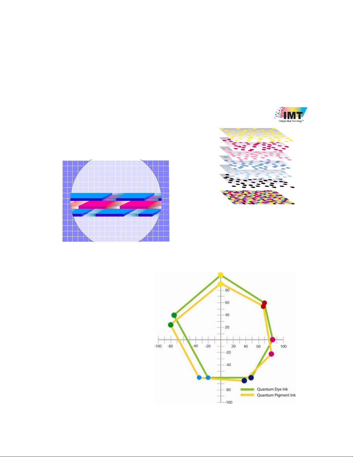
1. Intelligent Mask Technology (IMT)
- A simple screen that is applied to image
files by the printer to determine which dots
are printed during each swath (or print pass)
in a particular print mode selection. A
different print mask is applied for each color
plane.
- Two thermal-based ink types are available with the Kodak 1200i Wide-Format Printing
system: Quantum-Dye (Qi-Dye) and Qi-Pigment (Qi-Pig). The typical color range of the
Qi-Dye ink is approximately
17,500 and offers outstanding
color pop and with the majority of
inkjet-coated media types in the
industry. This ink is particularly
strong in the backlit applications
market. Qi-Pigment ink color is
near the16,500 range and offers
exceptionally brilliant color for a
thermal-based ink, particularly
on the Rapid Dry and
indoor/outdoor media sets.
Technical Training Guide 4
Page 5
KODAK 1200i WIDE-FORMAT PRINTING SYSTEM
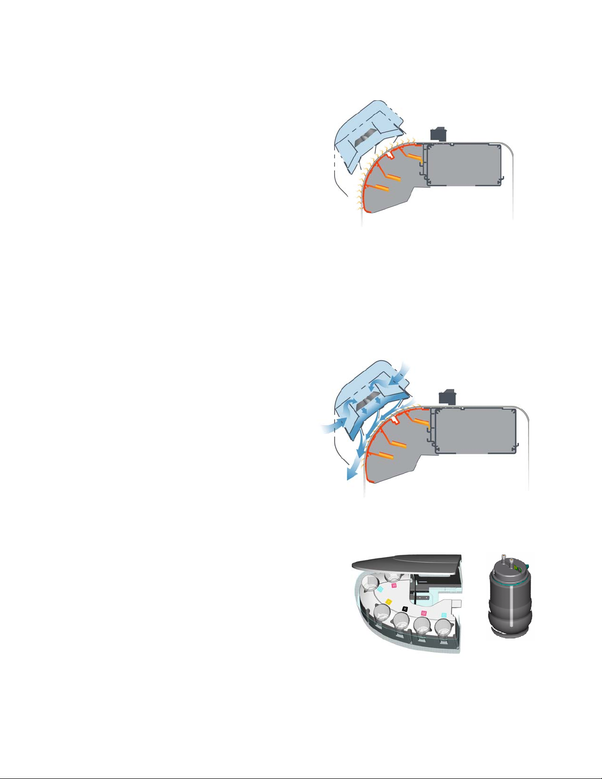
2. Rapid Dryer Technology
The advanced dual-component drying system
uses the principle of conducted heat to dry
printed images with much greater efficiency
than can be achieved with hot air dryers. The
media web is fed over a heated aluminum
nose that is curved to maintain intimate
contact with the back of the web for effective
heat transfer. The nose is an isolated
extrusion that incorporates three longitudinal
fins with an electrical heating strip mounted to
each fin inside the curve (each of the three
electrical heating strips provide up to 323 watts of power). This design evens out heat
flow to minimize cold spots under high density printed areas across the web without
the long warm-up time of a much thicker section. Ambient air flow is used to pull away
moisture and improve drying efficiency by another 30% over that achieved with the
heated nose alone. The application of ambient air flow also allows the system to apply
more drying power at a lower peak temperature for reduced risk of media damage.
Overall the drying system uses approximately 25% less energy over other drying
systems.
An ambient fan driven air plenum is used
to distribute air flow evenly across the
print width. Air flow is downward, carrying
heat away from the print zone to improve
nozzle reliability and to reduce the risk of
edge curl. An intelligent control system
regulates electrical power to achieve and
maintain temperature set points between
35 and 55 degrees C.
The air plenum may be lowered by
removing two locking pins to perform
printer maintenance.
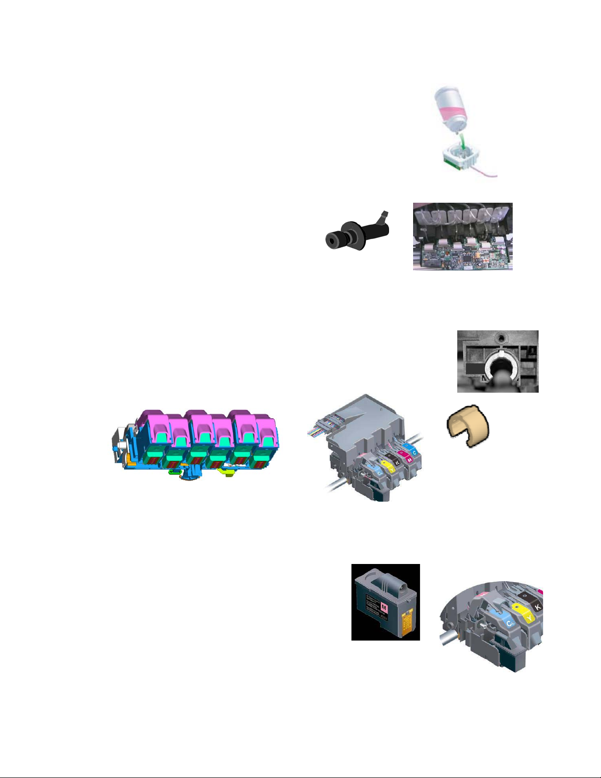
3. Ink System
a. Ink Reservoir:
- 6 ink reservoirs (ML, CL, Y, K, M, C)
- Ink bottles are easy to replace
- Encrypted for ink monitoring (700 ml)
- One set of ink lines; switch over capability
(Dye or Pigment)
- Plug and Play ink refill bottle (700 ml) with
septum/needle interface
- Clean-hands installation
- Mechanical color keying of bottle
Technical Training Guide 5
Page 6
KODAK 1200i WIDE-FORMAT PRINTING SYSTEM
c. Intermediate Reservoir:
- Intermediate reservoir located below ink bottle
- Provides consistent ink supply pressure (50 ml capacity)
- Replace ink on-the-fly (30 seconds); prevents job interruptions
- Optical sensor monitors reservoir ink levels [ink level LOW
warning sensor (<30ml; ~10-30 minutes) and ink level OUT stop
(<20ml), protects cartridge]
d. Ink Supply Dampers and Septum
Valve System:
- Ink flows through damper into a septum
assembly (spring actuated ball valve to
shutoff ink when cartridges are removed)
Note: ink is filtered at the cartridge only.
e. Carriage Assembly:
- Robust carriage bushing design; thick bushings with 2 shims for better
dimensional stability. Bushings are secured by bushing retainers.
- Bushings are grooved to minimize the effect of dirt and debris.
- Cartridge doors secure and bias print heads into proper position.
- One-step cartridge installation process; remove tape and install.
f. Cartridge / Printhead:
- Increased productivity with 640 nozzle print
heads.
- Clean hands shipping and installation.
- Foam filled, eliminate tubing and needles.
- Ink filter.
- 700 ml warranty; 2800 ml shutoff.
- 1400 ml average print head life.
Technical Training Guide 6
Page 7
KODAK 1200i WIDE-FORMAT PRINTING SYSTEM
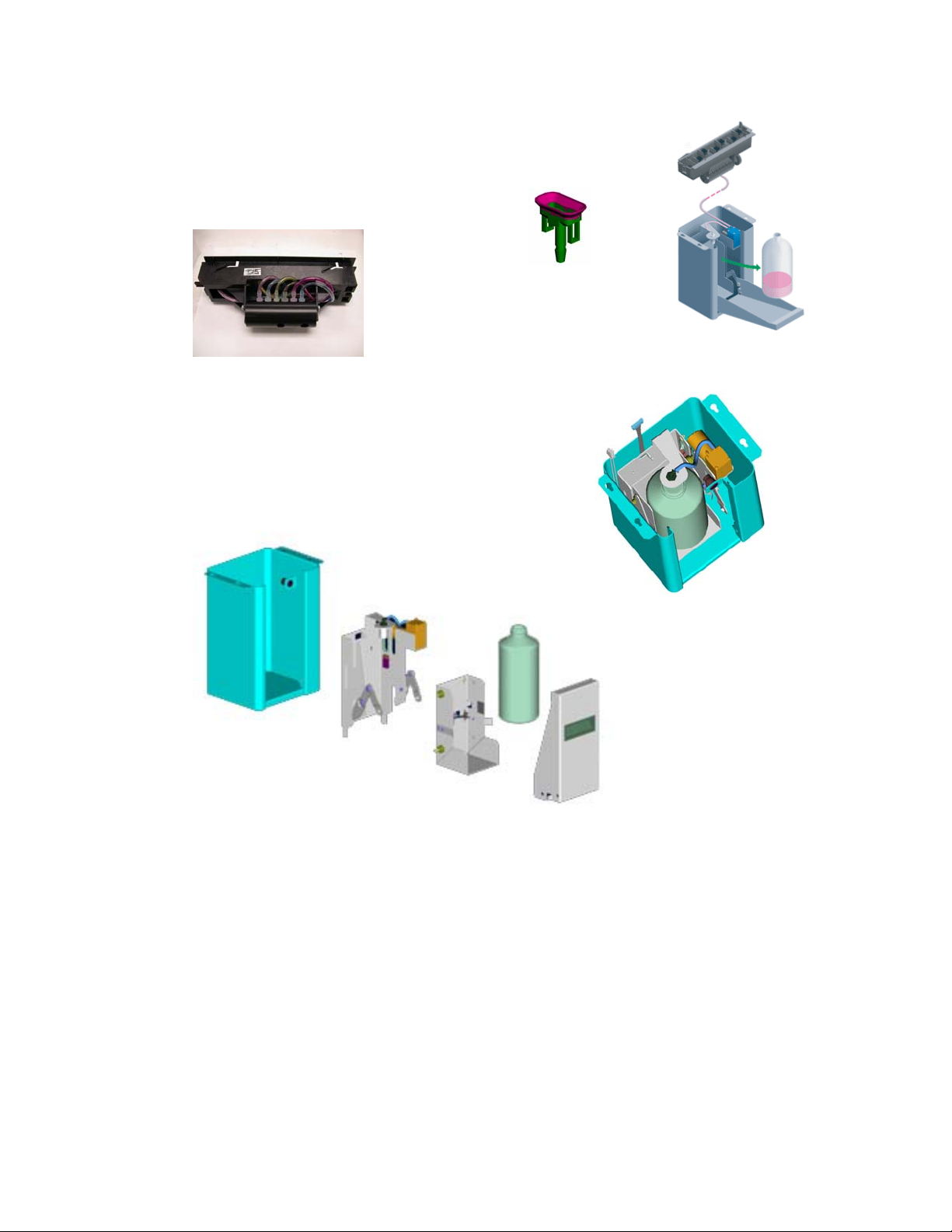
g. Service Station:
- Clean hands cartridge maintenance through service station
(Cartridge cleaning/System Prime).
- Ink is deposited into a waste disposal bottle.
h. Auto Clean Unit:
- Door Magnet
- Suction pump/motor (used for priming ink lines)
- Bottle full sensor (IR)
- Ink waste bottle
- Bottle present/empty sensor ((IIRR))
Technical Training Guide 7
Page 8
KODAK 1200i WIDE-FORMAT PRINTING SYSTEM
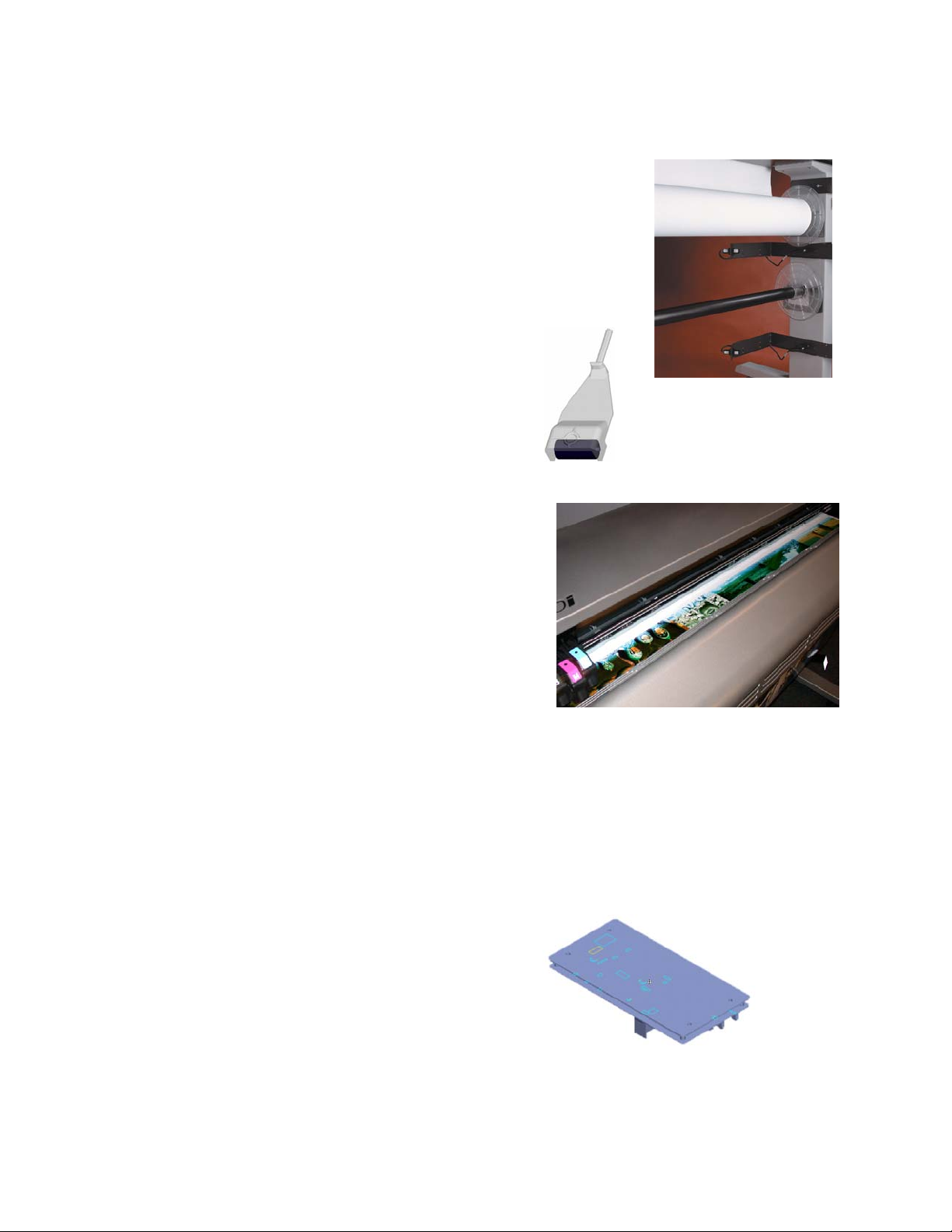
4. Media Handling System
- Four media supply modes are available: Sheet, Roll, Roll 2 and
TakeUp
- Media rolls can be easily exchanged with the removable media
spindles
- The Autoload paper sensor has a 6 second delay when media
is manually loaded at rear of printer
- The Roll 2 mode allows for a second roll of media to be loaded
onto the lower roller (no takeup mode available)
- The lower roller, new heavy duty stepper motor,
and new pinch roller design help better control
feed, paper travel and line length accuracy.
5. Print Speeds:
60 inch printer
High Speed Mode (2 pass): 220 sfph (20.4 smph)
Productivity Mode (3 pass): 150 sfph (14 smph)
Fine Mode (4 pass): 115 sfph (10.7 smph)
Enhanced Mode (6 pass): 75 sfph (7.0 smph)
8-Pass Print Mode 58 sfph (5.39 smph)
12-Pass Print Mode 37 sfph (3.44 smph)
High Quality (16 pass): 26 sfph (2.8 smph)
42 inch printer
High Speed Mode (2 pass): 195 sfph (18.1 smph)
Productivity Mode (3 pass): 140 sfph (13.0 smph)
Fine Mode (4 pass): 104 sfph (9.6 smph)
Enhanced Mode (6 pass): 70 sfph (6.5 smph)
High Quality (16 pass): 23 sfph (2.5 smph)
Note: printer ships with 64 MB SDRAM and is not up gradable; 32 MB RAM on Main PWA; HPGL/2 (vector file formats) is not supported
6. Power Supply:
Input Operating Range
90 – 132 and 180 – 264 VAC
Input Operating Frequency Range
43 – 67 Hz
Power Consumption
Typical: 1035 W; Idle: 20 W; Maximum: 1225 W
Output Voltage
24 VDC
Output Current
8.3 Amp. Maximum
Technical Training Guide 8
Page 9
KODAK 1200i WIDE-FORMAT PRINTING SYSTEM
Printer Installation
(Quick Steps)
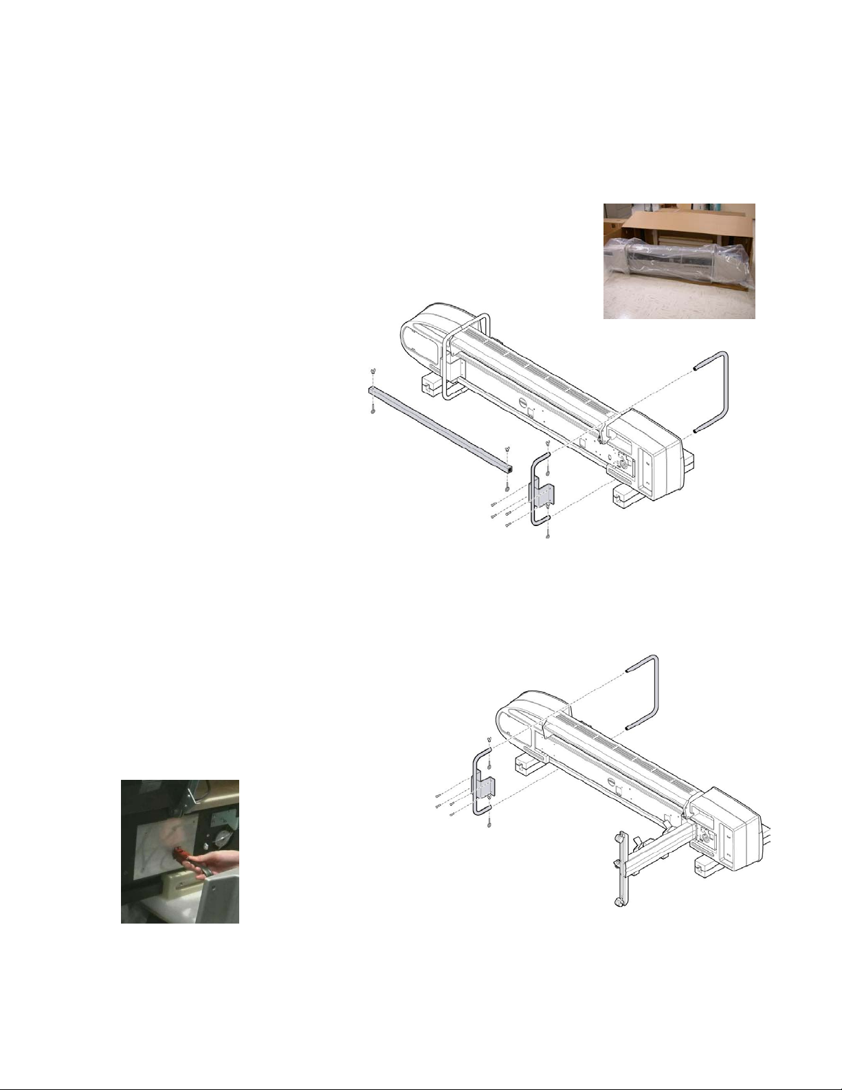
Step 1: Shipping Brackets Removal
- Rotate printer head box 90 degrees onto one side and remove
printer from large shipping box by pulling out and away from box.
- Before removing the shipping support brackets ensure the printer
is properly placed and balanced
on two or three strips of packing
foam provided.
- Remove the two (2) bolts
securing the metal crossbeam
between the support brackets.
- Remove upper and lower
shipping support brackets (four
bolts total) and install
appropriate stand leg to balance
the printer. Remove wing nut,
retaining bolt, and 4 screws.
Step 2:
- When installing the right stand leg attach electrical plug connection to printer base;
ensure the plug is aligned straight and square onto the connector to prevent damage to
the electrical pins. CAUTION: plug pins
are extremely fragile; ensure restraining
clips are secure.
- ‘Loosely’ attach the eight (8) stand leg
screws to the printer base; this will allow
for proper installation of the stand’s
crossbar.
Media System Installation (1 electrical connection)
CAUTION:
Avoid pushing
plug into the
platen assembly.
Technical Training Guide 9
Page 10
KODAK 1200i WIDE-FORMAT PRINTING SYSTEM
NOTE: It is suggested to assemble the right stand leg first, then attach the assembly to
the printer. Repeat with left stand leg assembly. Do not ‘completely’ tighten the screws
between stand legs and platen – only perform after the crossbar has been installed.
Step 3: Crossbar Installation
- Install crossbar between stand legs and
tighten four (4) securing screws.
- Tighten the eight (8) stand leg screws
after
the crossbar has been properly
installed.
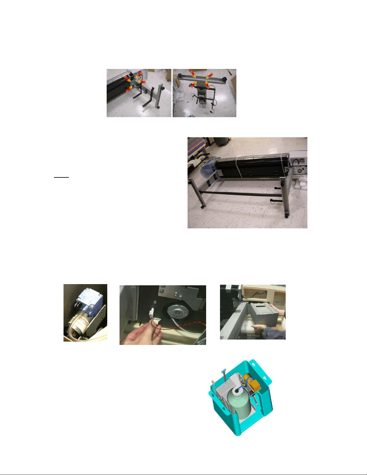
Step 4:
- To attach the auto clean unit first connect the ink tube line to the pump nipple. Attach
both electrical plug connections to respective jacks. Angle the assembly at a 45 degree
angle to connect over the 4 securing screws. Tighten four (4) securing screws.
Auto Clean Unit System (2 electrical connections/1 tubing connection)
- Verify the disposal bottle is installed and tubing
connections to bottle are intact.
Technical Training Guide 10
Page 11
KODAK 1200i WIDE-FORMAT PRINTING SYSTEM
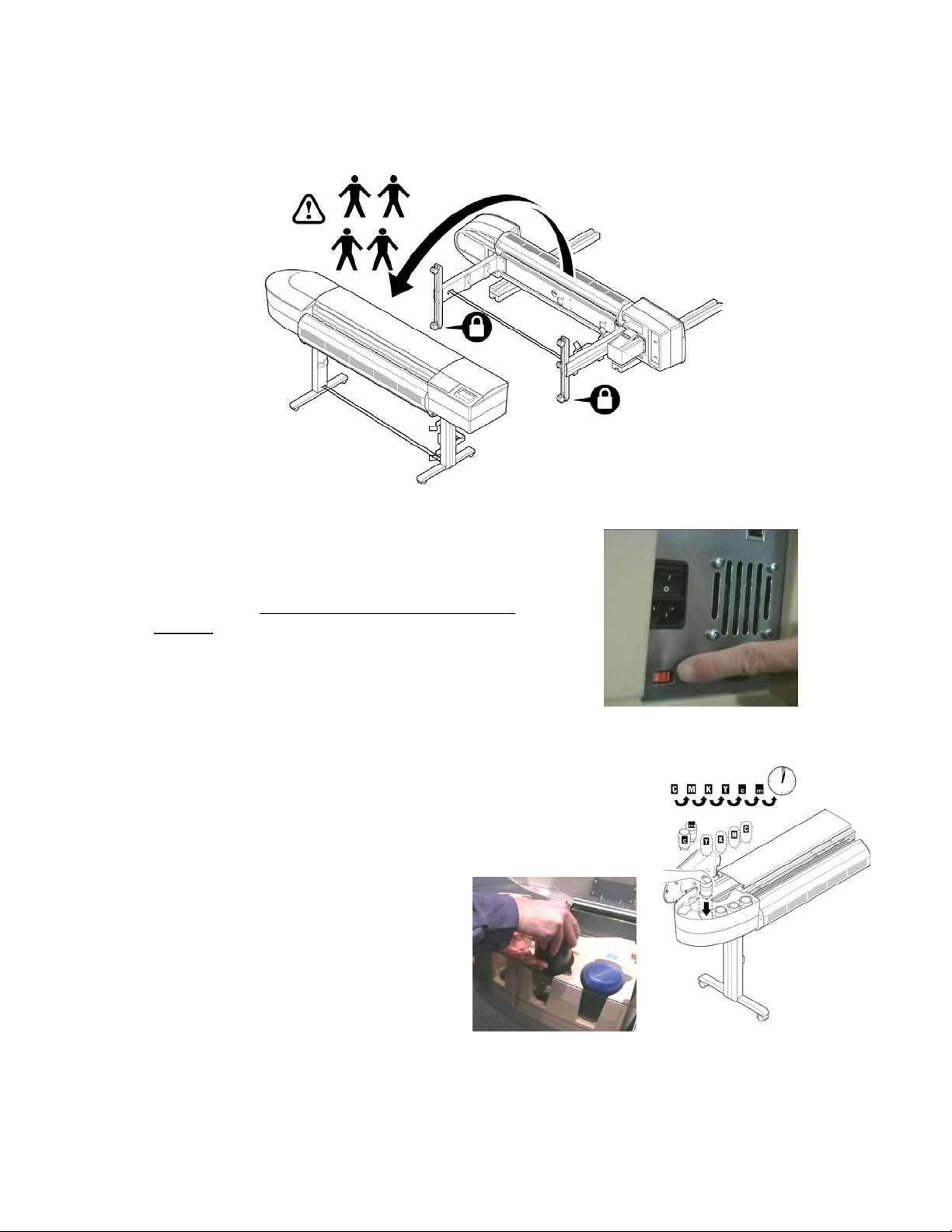
Step 5: Raise Printer
- Using a four (4) person lift gently raise printer to the standing position.
Step 6: Voltage Configuration (for dryer system)
Prior to powering on printer ensure the voltage selector
switch is set to either 115V or 230V depending on line
source.
NOTE 1: The voltage selector ships in the 230V
position.
NOTE 2: the circuit beaker will ‘pop’ out in an over-
current condition and will need to be replaced if this
occurs.
Step 7:
Reservoir Installation
When installing the six (6) ink bottles ensure each bottle is
installed straight up and down to avoid damaging pins at
intermediate reservoir (located at base).
Firmware Note:
C1 = C
M1 = M
Note: wait 5 minutes prior to
conducting line filling operation (using
‘Pump On’ from the control panel or
ink line may not fill properly.
L
L
NOTE: during normal operation you will have only 30 seconds to change ink
bottles during print operations or a printer STOP error will occur.
Technical Training Guide 11
Page 12
KODAK 1200i WIDE-FORMAT PRINTING SYSTEM
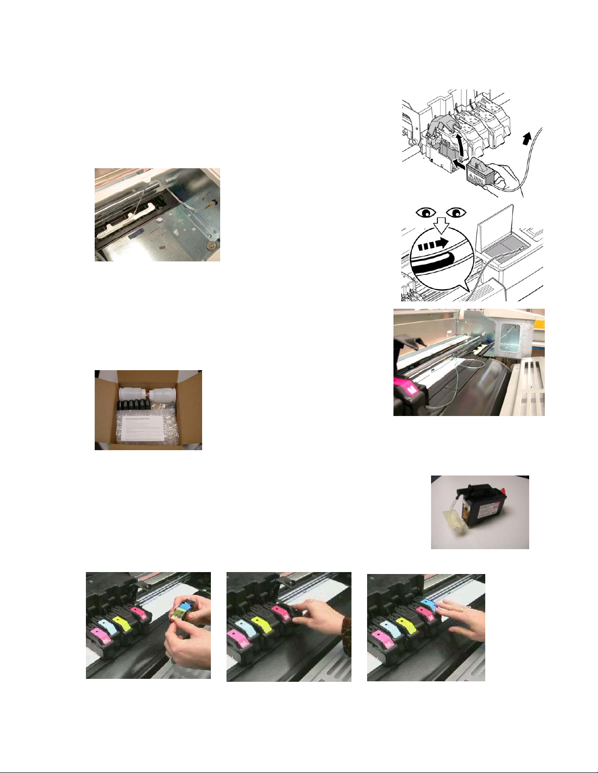
Step 8: Ink Line Filling
- After installing the 6 ink bottles and waiting 5 minutes, select
‘Access Cartridges’.
- Install the Cartridge with Tube Assembly into the first stall
position; attach tube needle to right side plate septum fitting
(under access cover).
NOTE: the cartridge with tube
assembly (+plug bar) ships in a
small box within the printer
head box.
- Activate tube fill by selecting and holding
Prime Menu – Service Station Menu – ‘Pump On’
Utility Menu -
.
- The fill process takes approximately 4-16 seconds per
color. When ink reaches the cartridge tube release the
‘Pump On’ selection. Repeat procedure for remaining colors.
NOTE:
To flush the ink system refer to
Technical Bulletin 2. Only use the
authorized Flush Kit (part number
221984-00) to evacuate ink lines and clean the system of ink
prior to printer transport.
Step 9: Cartridge Installation
Open cartridge door by pulling up on door at a 45 degree angle.
Remove tape from cartridge. Slide cartridge into cartridge stall and
close cartridge door until it locks.
Note: door must be closed to properly bias cartridge position.
Technical Training Guide 12
Page 13
KODAK 1200i WIDE-FORMAT PRINTING SYSTEM
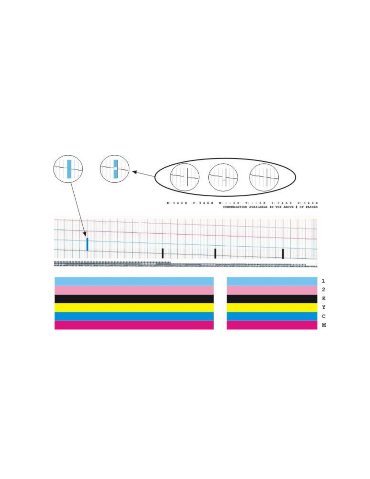
Step 10: Activate ‘Prime All’ Test Pattern
- To print the Prime pattern select Utility Menu - Prime Menu - Prime All. Verify
print head nozzle performance - ensure diagonal lines are smooth and clogged jets are
not present.
- If necessary perform Manual Jet Bypass for clogged or misfiring jets. Select
Menu – Calibration Menu – Open Jet Menu – Edit List Menu.
Scroll to particular
jet number which has the clog/problem and toggle off. Select Ok to save selection.
NOTE: A few ‘streaks’ or lines may appear in the pre-prime pattern area, this is
considered normal due to the unique 640 jet pattern printed.
Utility
Technical Training Guide 13
Page 14
KODAK 1200i WIDE-FORMAT PRINTING SYSTEM
Step 11:
Printer Calibrations
NOTE: Refer to Technical Bulletin 1 for the specific printing application required. Most
customers should use the following procedure to obtain the best print quality output.
A. Activate the dryer system to warm the printer up for optimum calibration
performance. Wait approximately 5 minutes after completing steps 1a and 1b below
before proceeding to Step 2.
a) Set dryer to a heat setting of 4 (Low Heat, Fans). At control panel select
Dryer Menu - Dryer Setting.
Select Next or Prev to a setting of 4 and press Ok.
Setup Menu –
b) Activate the dryer. At control panel select
Menu – Accessory Menu – Dryer Status.
Utility Menu – Service Menu – Diagnostics
The T1 and T2 (temperature sensors) will begin
to slowly climb to the target temperature value (i.e. 40 degrees C).
NOTE: the new calibration menu structure is different from the previous firmware
version; please review the 3 calibration paths available:
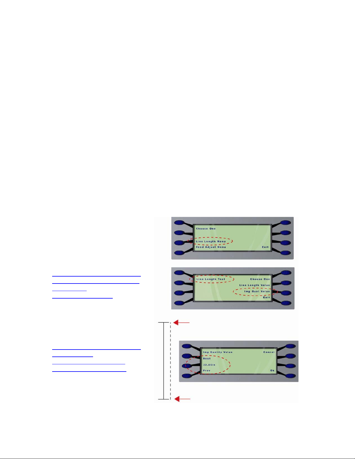
B. Activate the Line Length Test under Line Length Menu (
Menu – Paper Calib Menu - Line Length Menu – Line Length Test
Utility Menu – Calibration
), using a draftsman
ruler, measure and enter exact
value under
Image Quality Value
(i.e. 33.02 inches/83.90 cm).
NOTE: a 35 inch ruler print file
is provided on the System CD or
may be downloaded from the
Encad support web site
http://www.encad.com/Support/
Tech-Support-Resources/RTLTest-ImageDownloads/index.asp
The file can be printed using the
EFPU program supplied on
System CD (load software
utilities) or can be obtained from
the following link:
http://www.encad.com/Support/
Tech-SupportResources/ENCAD-TechSupport-Utilities/index.asp
Technical Training Guide 14
Page 15
KODAK 1200i WIDE-FORMAT PRINTING SYSTEM
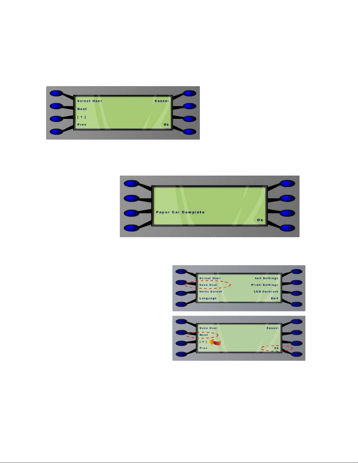
C. When printer calibration is complete the printer will display the Save User screen.
Select a save user number (i.e. 1 through 8) to be assigned for the media type currently
loaded. Select Ok.
Example Assignments:
User 1: Photo Satin, 180 g
User 2: Premium Backlit, 7 mil
User 3: PP Gls, 8 mil
User 4: Rapid Dry Gls, 190 g
User 5: Photo Gls, 160 g
User 6: Water Res Vinyl
A calibration complete message will be displayed on the control panel display. Select
Ok.
NOTE 1: do not select
‘Select User’ or any
previously entered data
will be overwritten.
Technical Training Guide 15
Page 16
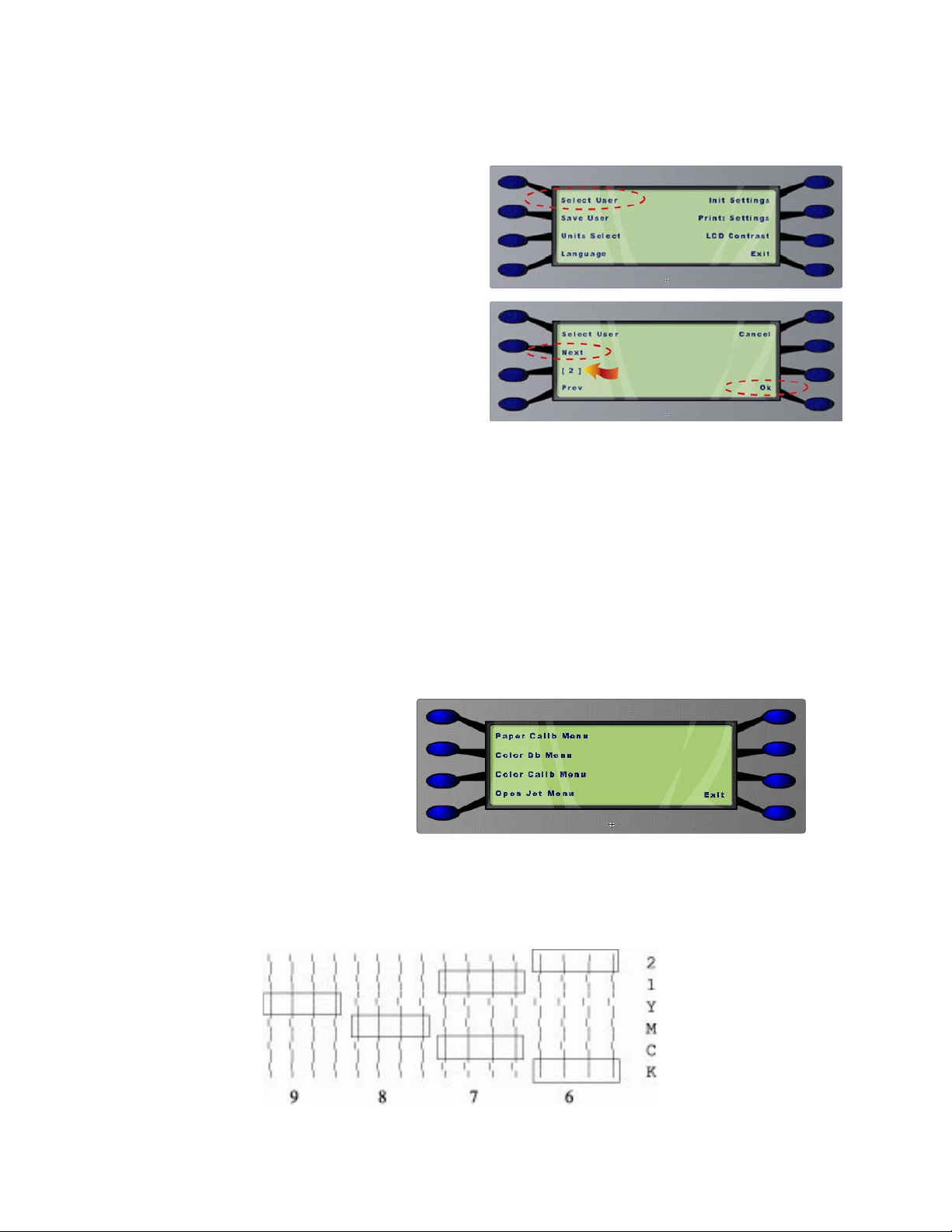
NOTE 2: When new media is loaded (or changed) the unique user setting
assigned must be chosen, select
Select the user
User.
number (1 through 8) that
was assigned for a
particular media type.
Select Ok.
Example Assignments:
User 1: Photo Satin, 180 g
User 2: Premium Backlit, 7 mil
User 3: PP Gls, 8 mil
User 4: Rapid Dry Gls, 190 g
User 5: Photo Gls, 160 g
User 6: Water Res Vinyl
NOTE 3: If the printer is powered off and on, User Setting 1 is
automatically initialized as a default operational setting. Refer to NOTE 2
above to “set” the proper calibration value for the media type loaded. If
the incorrect user setting is used then banding in printed output may
result due to the incorrect paper feed value being utilized. Media Feed
Adjust controls are better optimized and controlled from the Kodak 1200i
software suite.
D. Perform the other 3
calibrations as normal (Color
Deadband, Color Calibration
Horizontal, and Color Calibration
Vertical):
a) Color Db. Select Utility
Choose best group of aligned bars for each color. Perform whenever a new
Test.
Menu – Calibration Menu – Color Db Menu – Color Db
cartridge is installed.
KODAK 1200i WIDE-FORMAT PRINTING SYSTEM
Setup Menu – User Setup Menu – Select
Technical Training Guide 16
Page 17
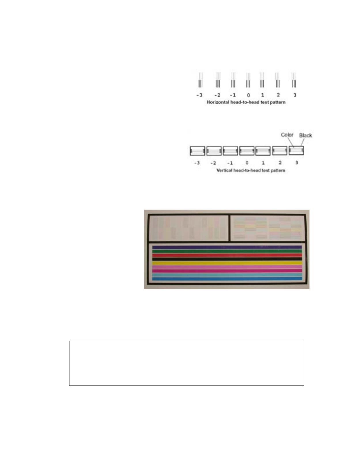
b) Color Cal Horizontal. Select
Horiz. Calib Test.
Choose best group
Utility Menu – Calibration Menu – Color Calib Menu -
of aligned bars for each set of colors.
Perform whenever a cartridge is
removed.
c) Color Cal Vertical. Select
– Calibration Menu – Color Calib
Menu - Vert. Calib Test.
Utility Menu
Choose best
group of aligned bars for each set of
colors. Perform whenever a
cartridge is removed or if the feed
adjust value is adjusted.
E. Activate the Internal Test Print. Select
will help verify the printer
calibrations are correct.
Inspect the vertical and
horizontal alignment between
all colors in the upper two
sections of the test print. If
vertical or horizontal
alignment is not achieved
then repeat step D.
KODAK 1200i WIDE-FORMAT PRINTING SYSTEM
Utility Menu – Service Menu – Test Print. This
Step 12: Best Quality Mode
To obtain the highest or optimum print quality mode from the printer place the print pass mode to 16.
To set the print-pass mode. Print pass mode will impact image output quality – refer to the
guidelines in the chart below:
Print Pass Modes: 2, 3, 4, 6, 8, 10, 12, 16
High speed print modes shown in BLACK
Default print mode shown in RED
Quality print modes shown in BLUE
Technical Training Guide 17
Page 18
KODAK 1200i WIDE-FORMAT PRINTING SYSTEM
Step 13. Networking (Peer-to-peer - Windows 2000/XP example)
The basic printer networking process is generally a 7-step process, but may vary
depending on network configuration/support. Refer to User System CD for additional
networking information as necessary.
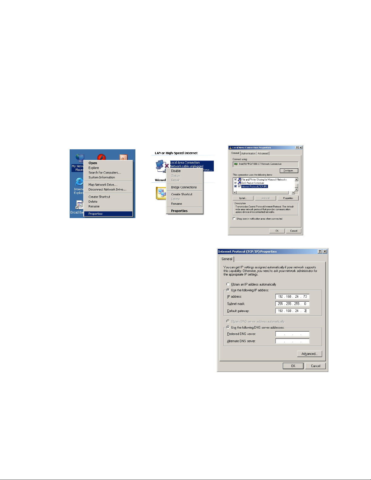
1). At the host computer (i.e. RIP workstation) assign network address settings.
a) At desktop right click on ‘My Network Places’ and select ‘Properties’. At
Local Area Connection window right click and select ‘Properties’. At local area
connection window select Internet Protocol and select ‘Properties’. If a TCP/IP
protocol is not listed then go ahead and install a TCP/IP protocol.
b) Assign workstation IP address (this
address should be one number different,
or very close to, from the printer’s address
for best results, i.e. 192.168.24.73).
Assign the Subnet mask and Default
gateway address (these addresses will
match the printer). DNS addresses are not
required unless internet/web access is
going to be assigned and available.
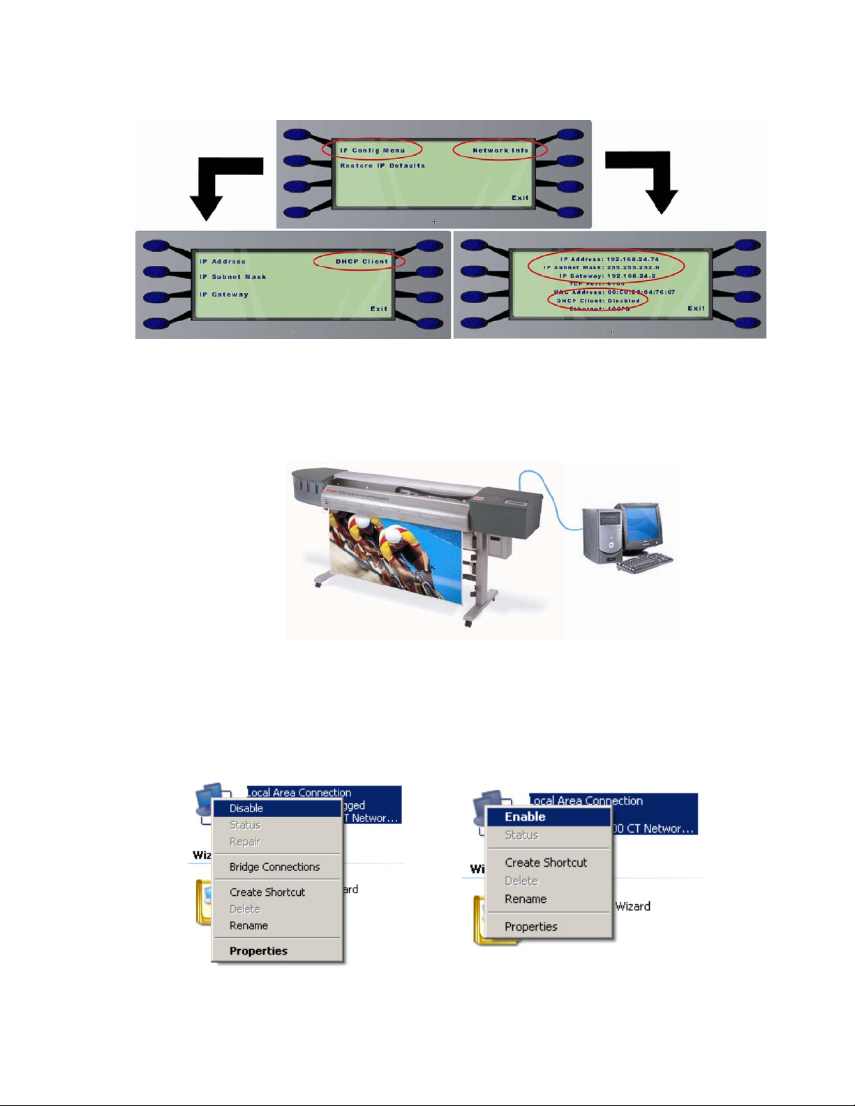
2). Assign IP address at printer (i.e.
192.168.24.74) – stay in the same ‘range’
as host computer from step 1 (i.e. one
number different from host workstation).
Select Setup Menu – Network Menu – IP
Address. Assign the Subnet mask and
Default Gateway addresses, these addresses must be exactly the same as
the host workstations. (see example above). Ensure DHCP (Dynamic Host
Control Protocol) is disabled unless advised by a network administrator that it
is required (a static IP address will need to be available in these types of
configurations).
Technical Training Guide 18
Page 19
KODAK 1200i WIDE-FORMAT PRINTING SYSTEM
3). Connect Ethernet ‘crossover’ cable between the host workstation and the
printer for direct connections (or an RJ-45 Ethernet patch cable from
HUB/switch to printer if indirectly connected).
4). At desktop right click on ‘My Network Places’ again and select ‘Properties’. At
Local Area Connection window select ‘Disable’. Then select ‘Enable’; this will
ensure the IP addressing has been refreshed (sometimes required on Win
2000/XP systems).
Technical Training Guide 19
Page 20
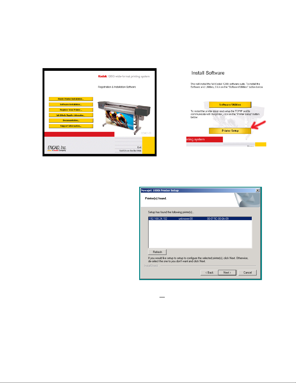
5). Load Windows Driver
a) Load the Kodak 1200i System CD into CD-ROM drive (CD should launch
automatically). Select Software Installation, then Printer Setup.
b) A Windows driver will be loaded (just follow the default button selections). If
configuration is successful the printer will be automatically detected across the
new network (Note: the
picture at right is an
example only; printer name
and IP address should be
displayed correctly). If the
printer is not located
perform steps 1-5 again.
NOTE: Ensure Subnet
mask and Default Gateway
addresses are assigned
and are the same at both
the printer and the
workstation.
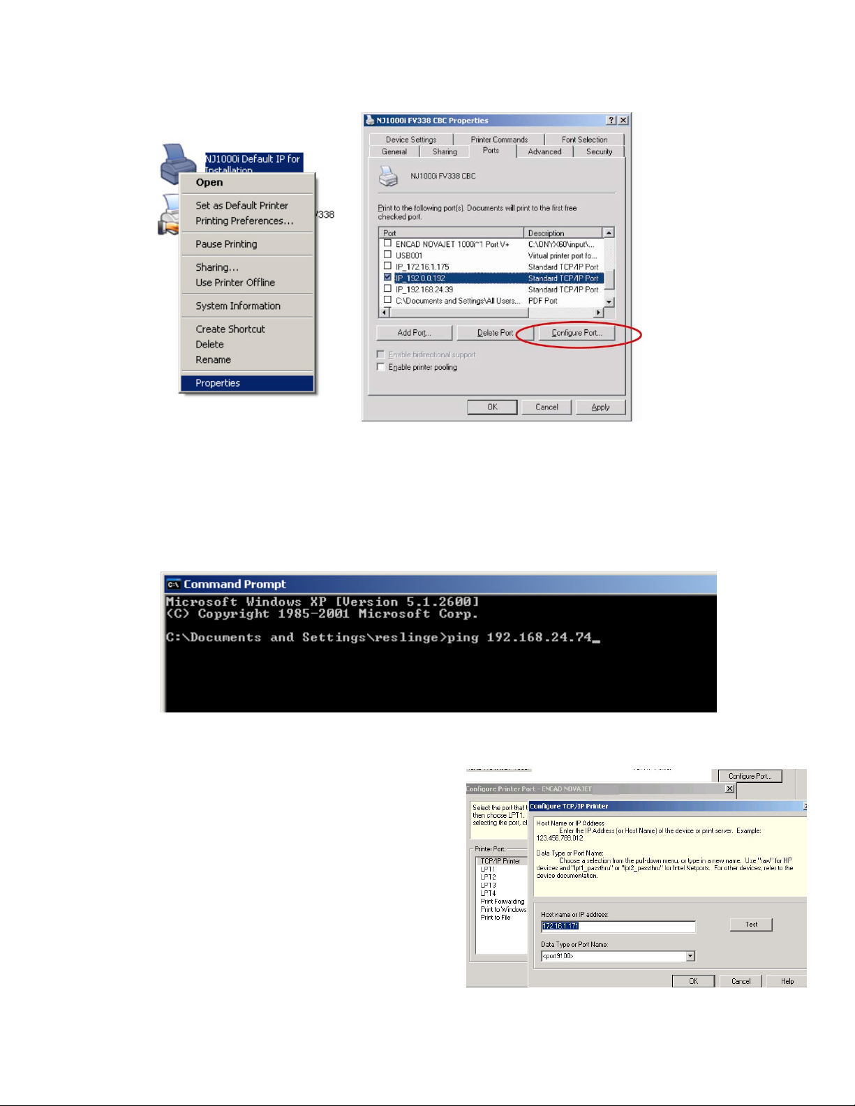
c) NOTE: If steps a. and b. above are unsuccessful then install a standard
TCP/IP printer port driver and configure or
existing NJ1000i/Kodak 1200i printer driver (or TCP/IP port) to match the
printers IP address. If necessary add a Standard TCP/IP driver (load Generic
text only driver) if not already installed. Open up Printers (START – SETTINGS
– PRINTERS). Select an existing TCP/IP port and choose ‘Configure Port’ if
making a modification; please note the port name will stay the same.
KODAK 1200i WIDE-FORMAT PRINTING SYSTEM
assign an IP address to an
Technical Training Guide 20
Page 21
KODAK 1200i WIDE-FORMAT PRINTING SYSTEM
6). At Command Prompt, ping the printer to verify connectivity between computer
and the printer. At computer select START – PROGRAMS – ACCESSORIES –
COMMAND PROMPT (or similar). Type: ping 192.168.24.74 (as an example)
and select ENTER. Four (4) ‘REPLY …..’ messages should appear. If
‘REQUESTED TIME OUT….’ messages appear then connectivity is incorrect –
verify steps 1 through 6 again.
7). Assign IP address at RIP (host
workstation) and set data type. The
IP address will be the same as the
printer’s IP address (i.e.
192.168.24.74). Data type must be
set to <9100> for proper data
transfer to occur. Pictured below is
ONYX’s printer port setup splash
screen; a port test may be activated
once values are set – a ‘Valid IP
Address!’ message should appear.
RIP and print operations may begin
at this point.
Technical Training Guide 21
Page 22
KODAK 1200i WIDE-FORMAT PRINTING SYSTEM
8). Configuration Double-check
(example only):
Workstation/Server:
IP: 192.168.24.73
Subnet: 255.255.255.0
Gateway: 192.168.24.2
- Windows Driver
Loaded
RIP:
IP: 192.168.24.74
- uses Windows
driver printer port
Printer:
IP: 192.168.24.74
Subnet: 255.255.255.0
Gateway: 192.168.24.2
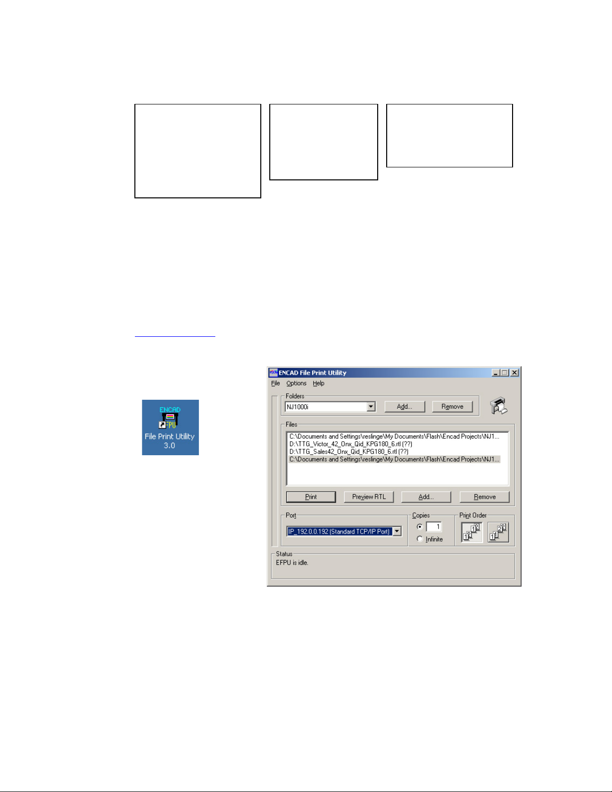
9). To further verify connectivity either send a test file to printer via RIP or from the
EFPU (Encad File Print Utility). Launch EFPU (if previously loaded) or load
EFPU (from User System CD, select Software Utilities, located EFPU utility and
load). Select port previously configured (normally identified by a default IP
address the first time loaded). Select the printer test file (link and open an
xxxxxx.rtl file from System CD images subfolder) and select ‘PRINT’. Printer
should start printing within 30 seconds if sending pre-ripped files to printer. To
download printer firmware (product enhancements/bug fixes) perform same
procedure with a firmware file (.rom file; may be obtained from
www.encad.com
); printer will sound a beep after approximately 60 seconds
and reboot power automatically.
NOTE: To function, the
EFPU utility may
require a LPT port be
available. Add a printer
port and assign to a
local LPT port if
necessary.
Technical Training Guide 22
Page 23
KODAK 1200i WIDE-FORMAT PRINTING SYSTEM
Step 14: Print Mode & Dryer Guidelines
NOTE: Go here for the most up-to-date information: http://www.encad.com/Printers/Kodak1200i/index.asp
Qi Dye
Photographic Papers
Kodak Premium Rapid-Dry Photographic Glossy / 260g (9 mil) 2 Production (3 Bi 10)
Kodak Premium Rapid-Dry Photographic Lustre / 260g (9 mil) 2 Production (3 Bi 10)
Kodak Rapid-Dry Photographic Glossy Paper / 190g (7 mil) 2 Production (3 Bi 10)
Kodak Rapid-Dry Photographic Satin Paper / 190g (7 mil) 2 Production (3 Bi 10)
Kodak Premium Photographic Glossy Paper / 270g (10 mil) 4 Production (3 Bi 10)
Kodak Premium Photographic Glossy Paper / 180g (8 mil) 4 Production (3 Bi 10)
Kodak Premium Photographic Satin Paper / 180g (8 mil) 6 Production (3 Bi 10)
Kodak Premium Photographic Matte Paper / 180g (8 mil) 4 Production (3 Bi 10)
Kodak Production Photographic Glossy Paper / 170g (7 mil) 10 Production (3 Bi 10)
Kodak Production Photographic Satin Paper / 170g (7 mil) 10 Production (3 Bi 10)
Photographic Films
Kodak Premium Backlit Film / 7 mil 10 (No Fans) Production (3 Bi 10)
Kodak Universal Backlit Film / 8 mil 2 Production (3 Bi 10)
Kodak Production Backlit Film / 7 mil Fans Only Enhanced (6 Bi 10)
Kodak Production Reverse Print Backlit Film / 5 mil 4 Enhanced (6 Bi 10)
Kodak Premium White Film / 5 mil 6 Production (3 Bi 10)
Kodak Production Glossy Poly Poster Plus / 8 mil 10 Production (3 Bi 10)
Kodak Production Satin Poly Poster Plus / 8 mil 10 Production (3 Bi 10)
Kodak Production Self-Adhesive Glossy Poly Poster Plus / 6 mil 10 Production (3 Bi 10)
Kodak Production Self-Adhesive Satin Poly Poster Plus / 6 mil 10 Production (3 Bi 10)
Kodak Self-Adhesive Glossy Poly Poster / 120g 10 Production (3 Bi 10)
Kodak Self-Adhesive Matte Poly Poster / 120g 10 Production (3 Bi 10)
Coated Papers
Kodak Coated Matte Print Paper / 140g (6 mil) (1) Fans Only Fine (4 Bi 10)
Kodak Coated Matte Print Paper / 90g (4 mil) (1) Fans Only Fine (4 Bi 10)
Kodak Self-Adhesive Coated Matte Print Paper / 100g (7 mil) (1) Fans Only Production (3 Bi 10)
Vinyl & Banners
Kodak Water-Resistant Removable Vinyl / 6 mil 2 User Defined (8 Bi 10)
Kodak GO Water-Resistant Self-Adhesive Vinyl / 6 mil 2 Enhanced (6 Bi 10)
Kodak Water-Resistant Scrim Banner / 17 mil 6 Enhanced (6 Bi 10)
Kodak Water-Resistant Poly Poster Matte / 8 mil 2 User Defined (8 Bi 10)
Kodak Water-Resistant Self-Adhesive Poly Poster Matte / 9 mil 2 User Defined (8 Bi 10)
Kodak Production Removable Glossy Vinyl / 6 mil 10 Production (3 Bi 10)
Kodak Production Removable Satin Vinyl / 6 mil 10 Production (3 Bi 10)
Canvas
Kodak Artists’ Semigloss Canvas / 20 mil (1) Fans Only Production (3 Bi 10)
Kodak Matte Canvas / 19 mil (1) Fans Only Production (3 Bi 10)
Recommended Printer
Heater Setting (1)
Recommended Print
Mode*
(1): Based on room conditions of 23C/50% RH. *: Recommended mode for photo
image quality 3 Bi 10 = 3 pass, bidirectional, 10 speed 4 Bi 10 = 4 pass,
bidirectional, 10 speed 6 Bi 10 = 6 pass, bidirectional, 10 speed 8 Bi 10 = 8 pass,
bidirectional, 10 speed
Technical Training Guide 23
Page 24

KODAK 1200i WIDE-FORMAT PRINTING SYSTEM
Qi Pigment
Photographic Papers
Kodak Premium Rapid-Dry Photographic Glossy / 260g (9 mil) 2 Fine (4 Bi 10)
Kodak Premium Rapid-Dry Photographic Lustre / 260g (9 mil) 2 Fine (4 Bi 10)
Kodak Rapid-Dry Photographic Glossy Paper / 190g (8 mil) 2 Fine (4 Bi 10)
Kodak Rapid-Dry Photographic Satin Paper / 190g (8 mil) 2 Fine (4 Bi 10)
Photographic Films
Kodak Universal Backlit Film / 8 mil 2 Production (3 Bi 10)
Coated Papers
Kodak Coated Matte Print Paper / 140g (6 mil) Fans Only Enhanced (6 Bi 10)
Kodak Self-Adhesive Coated Matte Print Paper / 100g (7 mil) Fans Only Fine (4 Bi 10)
Vinyl & Banners
Kodak Water-Resistant Removable Vinyl / 6 mil 2 User Defined (8 Bi 10)
Kodak GO Water-Resistant Self-Adhesive Vinyl / 6 mil 2 Enhanced (6 Bi 10)
Kodak Water-Resistant Scrim Banner / 17 mil 6 Enhanced (6 Bi 10)
Kodak Water-Resistant Poly Poster Matte / 8 mil 2 Enhanced (6 Bi 10)
Kodak Water-Resistant Self-Adhesive Poly Poster Matte / 9 mil 2 Enhanced (6 Bi 10)
Canvas
Kodak Artists’ Semigloss Canvas / 20 mil 2 Production (3 Bi 10)
Kodak Matte Canvas / 19 mil Fans Only Fine (4 Bi 10)
Recommended Printer
Heater Setting (1)
Recommended Print
Mode*
(1): Based on room conditions of 23C/50% RH. *: Recommended mode for photo image quality 3
Bi 10 = 3 pass, bidirectional, 10 speed 4 Bi 10 = 4 pass, bidirectional, 10 speed 6 Bi 10 = 6 pass,
bidirectional, 10 speed 8 Bi 10 = 8 pass, bidirectional, 10 speed
NOTE: If dryer temperature is too high on certain backlit media vertical banding
(swaths) may be observed in printed output. Lower the dryer temperature if this occurs.
Technical Training Guide 24
Page 25

KODAK 1200i WIDE-FORMAT PRINTING SYSTEM
)
Step 15: Lamination Guidelines
Kodak Media Lamination Reference for Kodak 1200i Printer
Qi Dye
Lamination Compatibility#
Heat
Activated
Thermal
Heat Activated
Low
Temperature
Heat
Assisted
Pressure
Sensitiv e
Ambient
Photographic
Kodak Rapid-Dry Photographic Glossy Paper / 200g (8 mil) Yes Yes Yes Yes
Kodak Rapid-Dry Photographic Satin Paper / 200g (8 mil) Yes Yes Yes Yes
Kodak Premium Photographic Glossy Paper / 270g (10 mil) Yes Yes Yes Yes
Kodak Premium Photographic Glossy Paper / 180g (8 mil) Yes Yes Yes Yes
Kodak Premium Photographic Satin Paper / 180g (8 mil) Yes Yes Yes Yes
Kodak Premium Photographic Matte Paper / 180g (8 mil) Yes Yes Yes Yes
Kodak Economy Photographic Glossy Paper / 160g (6 mil) No No No Yes
Kodak Economy Photographic Satin Paper / 160g (6 mil) No No No Yes
Coated
Kodak Coated Matte Print Paper / 140g (6 mil) No No Yes Yes
Kodak Coated Matte Print Paper / 90g (4 mil) No No Yes Yes
Kodak Self-Adhesive Coated Matte Print Paper / 100g (7 mil) No Yes Yes Yes
Film
Indoor:
Kodak Premium Backlit Film (7 mil) Yes Yes Yes Yes
Kodak Premium White Film (5 mil) Yes Yes Yes Yes
Reverse Print Backlit VS (5 mil) No No Yes Yes
Kodak Poly Poster Glossy (7 mil) No No No Yes
Kodak Poly Poster Satin (7 mil) No No No Yes
Indoor/Outdoor:
Kodak Reverse Print Backlit Film (6 mil) Yes No No Yes
Kodak Water-Resistant Backlit Film (8 mil) Yes No Yes Yes
Kodak Water-Resistant Poly Poster Matte (8 mil) Yes Yes Yes Yes
Kodak Water-Resistant Self-Adhesive Poly Poster Matte (9 mil
Kodak Self-Adhesive Glossy Poly Poster (120g) No No No Yes
Kodak Self-Adhesiv e Matte Poly Poster (120g) No No No Yes
Yes Yes Yes Yes
Vinyl
Kodak GO Water-Resistant Scrim Vinyl No
Kodak GO Water-Resistant Self-Adhesive Vinyl No Yes Yes Yes
KODAK W ater-Resistant Removable Vinyl No Yes Yes Yes
KODAK Water-Resistant Scrim Banner
No No No Yes
NA NA
Yes
Specialty
Fine Art:
Kodak Artists’ Semigloss Canvas (20 mil) NA NA NA NA
Kodak Matte Canvas (19 mil) No No No Yes
Indoor/Outdoor:
Kodak GO Banner/Dupont Tyvek material (9 mil)
Kodak GO Wet Strength Paper (11 mil) Yes Yes Yes Yes
Kodak GO Polyethylene Banner (10 mil) Yes Yes Yes Yes
Kodak Water-Resistant Reinforced Flex Banner (15 mil) Yes Yes Yes Yes
NA = Not Applicable
#: Check with laminate manufacturer for suitability of outdoor use
*: Recommended mode for photo image quality
Yes Yes Yes Yes
Technical Training Guide 25
Page 26

KODAK 1200i WIDE-FORMAT PRINTING SYSTEM
)
Kodak Media Lamination Reference for Kodak 1200i Printer
Qi Pigment
Lamination Compatibility#
Heat
Activated
Thermal
Heat Activated
Low
Temperature
Heat
Assisted
Pressure
Sensitive
Ambient
Photographic
Kodak Rapid-Dry Photographic Glossy Paper / 200g (8 mil) Yes Yes Yes Yes
Kodak Rapid-Dry Photographic Satin Paper / 200g (8 mil) Yes Yes Yes Yes
Coated
Kodak Coated Matte Print Paper / 140g (6 mil)
Kodak Self -Adhesiv e Coated Matte Print Paper / 100g (7 mil)
No No Yes Yes
No No
Yes Yes
Film
Indoor/Outdoor:
Kodak Reverse Print Backlit Film (6 mil) Yes
Kodak Water-Resistant Backlit Film (8 mil) Yes Yes Yes Yes
Kodak Water-Resistant Poly Poster Matte (8mil) Yes Yes Yes Yes
Kodak Water-Resistant Self-Adhesive Poly Poster Matte (9 mil
Yes Yes Yes Yes
No
Yes Yes
Vinyl
Kodak GO Water-Resistant Scrim Vinyl
Kodak GO Water-Resistant Self-Adhesive Vinyl No Yes Yes Yes
KODAK W ater-Resistant Remov able Vinyl No Yes Yes Yes
KODAK W ater-Resistant Scrim Banner
No
No No No Yes
NA NA
Yes
Specialty
Fine Art:
Kodak Artists’ Sem igloss Canv as (20 mil)
Kodak Matte Canvas (19 mil)
NA NA NA NA
No No No
Yes
Indoor/Outdoor
Kodak GO Banner/Dupont Tyvek material (9 mil)
Kodak GO W et Strength Paper (11 mil) Yes Yes Yes Yes
Kodak GO Polyethylene Banner (10 mil) Yes Yes Yes Yes
Kodak Water-Resistant Reinforced Flex Banner (15 mil) Yes Yes Yes Yes
NA = Not Applicable
#: Check with laminate manufacturer for suitability of outdoor use
*: Recommended mode for photo image quality
Yes Yes Yes Yes
Technical Training Guide 26
Page 27

KODAK 1200i WIDE-FORMAT PRINTING SYSTEM
PPrriinntteerr OOppeerraattiioonn TTiippss
1. Media Load and Verification
- Install media onto spindle and attach the media guide
and tighten the blue locking nut. Verify spindle gears
mesh properly. Ensure left media guide is locked next
to the white alignment mark. Adjust right media guide
to within 2 mm of media edge. Load media into the rear
of printer, align with white alignment mark.
NOTE: paper will be automatically advanced following
a 6 second delay and then measured. Verify load was
successful under
- Install the front left and right Paper Guides (these help guide media under the air plenum)
and install the magnetic media holders
directly above the left and right edges of the media surface
below; parts are actually black or white in color).
Utility Menu - Display Settings.
(help prevent media head strike) onto the Y-Arm
(NOTE: illustrated in yellow
NOTE: After loading media a friendly reminder control panel message ‘Warning – Adjust
Rear Paper Guides…’ will appear.
- Ensure both rear paper guides are not touching media edges (2
mm offset minimum on both sides). This is very important as
media drag may occur at either the left or right sides (causes left
or right side micro-banding). Also ensure media is not rubbing or
‘climbing’ over guides at any time during printing.
CAUTION: once media has been aligned and guides
have been set, typically the media may "glide" against
one guide or the other but not to the point where media
jumps on top of the guide (see picture at left). Verify
media is initially loaded with the offset to ensure that
the media is not wedged between the two guides. This
can lead to left or right side horizontal banding on
printed output.
Technical Training Guide 27
Page 28

KODAK 1200i WIDE-FORMAT PRINTING SYSTEM
2. The ‘Perfect’ Media Load
- After loading media in the normal routine, it is best to perform a ‘perfect media load’.
Hold the feed roller guide (round plastic guide) at
right side with one hand and then simultaneously
press the
media forward until it pulls against the media roll,
keep holding (do not allow guide to rotate) for
another 10 seconds or so - resistance is the key
to pull the media straight.
NOTE: the media guides should be pulled all the
way out when loading media (see Caution
above). Also, once the media is tight, driving media ‘forward’ aids in alignment.
Feed Media - Forward button. Drive
3. Dryer Modes
To activate the drying system, select Setup Menu -
Dryer Menu
modes are available; refer to dryer matrix label affixed to
printer’s top cover or Installation Step #14 above
specific modes of operation.
NOTE 1: The air plenum may be lowered to the maintenance position by removing 2
locking pins and gently lowering plenum. The air plenum should be only be lowered
when performing printer calibrations and replacing cartridges.
NOTE 2: The air plenum may also be completely removed for certain media print
applications (i.e. 50” bond media) where the media becomes obstructed by the air
plenum. Contact technical support for assistance with removal.
. Scroll through available selections. 12 dryer
0 = OFF
1 = Fans Only
2 = Minimum, Fans On
3 = Minimum
4 = Heat Low, Fans On
5 = Heat Low
6 = Heat Medium, Fans On
7 = Heat Medium
8 = Heat High, Fans On
9 = Heat High
10 = Maximum, Fans On
11 = Maximum
for
Technical Training Guide 28
Page 29

KODAK 1200i WIDE-FORMAT PRINTING SYSTEM
4. Humidity Control
Ideal humidity for printing is between 45 and 55 percent, at a temperature of 68-72
degree F. (20-22.2 degrees C.)
Low Humidity problems:
1) Media warping and edge curl problems leads to visible
carriage head strike on media surface.
2) Inconsistent print quality is normally observed in severe
low humidity environments. To compensate more ink must
be used to balance the color loss (need for color profiling).
High humidity problems:
1) Dry time drastically increases with high humidity levels.
2) Lamination issues often result; increasing time required to finish jobs. Refer to
Installation Step #15 above
These problems can be avoided by maintaining proper temperature and humidity levels
(RH) in both storage and operational areas. The use of humidifiers will add water to the
air, resulting in a humidity level increase. This will help prevent normal heating season
problems caused by dry air.
General Environmental Conditions
Controlling the print location and surrounding humidity is key toward maintaining good
color output no matter what environment or region the printer is located in.
for lamination guidelines.
5. Edge Band mode
To eliminate instances of ‘First Drop’ (color change at print edges) from occurring ensure
the Edge Band mode is turned on. Select
Margins
vertical bar of 6 colors will be printed along both media edges. This will force the
cartridges to warm up by
printing data outside the
page layout, thus
decreasing the chances of
‘First Drop’ from appearing
along printed edges.
. By selecting Edge Band the printer will be forced into Normal Margins and a
Setup Menu – Paper Option Menu –
Technical Training Guide 29
Page 30

KODAK 1200i WIDE-FORMAT PRINTING SYSTEM
SSooffttwwaarree CCoonnttrrooll TTiippss
1. Typical Server Installation (one per subnet)
- For most installations perform the ‘typical’ installation of the Kodak 1200i software
suite. This is ideal for most environments including those using a single computer
single printer configuration. Note: this software only runs on Windows®
2000/2000/2003 Pro/Server and XP/XP Pro.
NOTE: Verify another Microsoft SQL database is not loaded or being used by customer
on same subnet – do not load the software suite or conflicts may be encountered.
- For peer-to-peer connections use an Ethernet crossover cable otherwise use a
regular Ethernet patch cable through a Switch (100FD capable). Configure the
TCP/IP address either through the software installation instructions or directly at
the printer under Setup Menu – Network Menu.
2. Client Installation (one per workstation)
- Install the Client Installation package onto additional workstations that will be
printing to the printer (in addition to the server workstation). Note: the database
program (MSDE) should only be installed onto the primary server workstation (one
subnet per server).
NOTE: While the software suite is not required to run the RIP or drive the printer, the NJ1000i
driver will normally need to be loaded for most RIPs to communicate properly with the printer (one
exception is NT 4.0). The primary advantage of loading the printer software is easy setup on the
network, job accounting features,
media feed calibration (best
operational feature!), ink usage
and allowing remote control over
the printer settings. If the software
is not registered the job
accounting elements will become
disabled after 90 plot hours –
perform product registration via
the Client software under Help.
Technical Training Guide 30
Page 31

KODAK 1200i WIDE-FORMAT PRINTING SYSTEM
PPrriinntteerr M
Maaiinntteennaannccee
WWhheenn aa PPrriinntt HHeeaadd iiss RReeppllaacceedd::
A. Check for air bubbles in the ink delivery line after replacing a print head:
- Perform an “Access Cartridge”
- Check for air segments of more than 5mm in length in the ink tubes; air bubbles are
acceptable but LARGE air segments are NOT acceptable.
Perfect Air bubbles acceptable NOT ACCEPTABLE
- If necessary, perform an ink load on ink lines which contain large air segments. Air
bubbles will be removed by a System Prime (must have new service station and f/w
1.5.0 or greater already installed).
- Select
Utility Menu - Prime Menu - Serv. Station Menu – System Prime. The System
Prime will take approximately 60 seconds to complete; all bubbles should be removed.
B. If air segments remain or ink line is completely empty:
- Install the Plug Bar and attach the ink line fitting to right side plate septum fitting;
remove the Print head and replace it with the Ink Load cartridge.
- Select
Utility Menu - Prime Menu - Serv. Station Menu - Pump On (hold button for 15
seconds).
- If this problem appears frequently after removing
and installing multiple print heads, then septum may need replacement (contact
Technical Training Guide 31
Page 32

KODAK 1200i WIDE-FORMAT PRINTING SYSTEM
service).
C. After replacing a print head, it is a good practice to run the System Prime. This will
improve ink flow through the ink system and reduce print head errors.
NOTE: ensure printer is placed on a level
floor surface to avoid ink starvation (which
could cause ‘MAX INK TEMP EXCEEDED’
error messages) and related ink flow
problems. Check printer levelness by
placing a standard level on the platen
surface (remove media from platen).
Perform the following:
- A System Prime:
Select Utility Menu - Prime Menu - Serv. Station Menu - System Prime
- Print a Prime Test to check that all nozzles are properly firing
Select Utility Menu - Prime Menu - Prime Single - Prime
- Perform Print head alignments:
Bi-directional alignment:
Color Db Test
Geometric print heads alignment: Utility Menu / Calibration Menu / Color
Calib Menu / Vert. Calib Test / Horiz. Calib Test
Prime Test Color Dead Band Vertical Calibration
Utility Menu / Calibration Menu / Color Db Menu /
Horizontal Calibration
Technical Training Guide 32
Page 33

KODAK 1200i WIDE-FORMAT PRINTING SYSTEM
RRoouuttiinnee MMaaiinntteennaanncce
e
IMPORTANT: It is suggested to perform a weekly cleaning action on the printer (i.e.
every Monday morning for 20 minutes) instead of attempting to remember the user
guide cleaning intervals.
A. Clean the following assemblies:
1. Encoder Strip (lint-free swabs dampened with Windex® or a mild dish soap and
water solution). Thoroughly clean the top and bottom surfaces of the entire length
of the encoder strip (including the area near the service station; access cartridges
to move carriage out). Repeat procedure with new swabs until no ink residues are
observed on swab surfaces.
NOTE: Windex solution should be mainly used on printers running pigment inks.
2. Service Station (lint-free towel/lint-free swab dampened with a mild dish soap &
water solution). Gently clean service station seals & wipers; ensure the outside
edges of the wipers are thoroughly cleaned.
CAUTION: do not remove the service station to clean (only Authorized Service
Providers should remove the service station when necessary).
3. Slide Shaft (lint-free towel dampened with Windex solution or isopropyl alcohol).
Thoroughly clean the entire length of the slide shaft, including the portion near the
service station zone.
NOTE: do not apply solutions directly on the
carriage bushings; allow shaft to dry before
moving carriage assembly.
Technical Training Guide 33
Page 34

KODAK 1200i WIDE-FORMAT PRINTING SYSTEM
4. Platen Surface & Cutter Groove (lint-free swab/lint-free towel dampened with
Windex or a mild dish soap & water solution). Remove media from printer and wipe
down platen and cutter groove until ink residues are no longer visible on cleaning
swab/towel. Using a toothpick or paperclip, gently remove paper fibers or similar
debris from the cutter groove.
5. Carriage Belt (lint-free towel dampened with Windex or a mild dish soap & water
solution). Thoroughly clean the entire length of the inside surface of carriage belt).
6. Flex Driver Cables (lint-free towel or lint-free swab
dampened with Windex solution or isopropyl alcohol).
Remove all print heads from carriage assembly. Thoroughly
clean all 6 (six) carriage flex driver cables; ensure no lint
fibers or ink residues remain on cable surfaces.
NOTE: Routine cleaning of the flex driver cables is very
important when the printer is running in certain print
modes [print pass modes 2, 3, 4 and GB Mode available in firmware >2.1.0].
NOTE 2: If ink residue is observed on cable surfaces at any time printing should
be immediately suspended and a flex cable and rear cartridge cleaning
maintenance actions should be performed. Also refer to section B below.
CAUTION: Print heads may become damaged if media is allowed to scrape
against the lower jet plate surface during printing or through direct contact with
ink residues on service station seals when the carriage is at the home position.
Technical Training Guide 34
Page 35

KODAK 1200i WIDE-FORMAT PRINTING SYSTEM
7.
Carriage Guide and Carriage Slider (lint-free towel dampened with Windex or a
mild dish soap & water solution). Thoroughly clean the printer rear plate carriage
guide (horizontal shelf) and carriage slider. A dirty carriage guide and/or slider can
lead to carriage vibration and printer banding.
8. Lower Roller/Pinch Rollers (lint-free towel dampened with a mild dish soap &
water solution). To clean, apply power to the printer. Advance rollers using the
control panel’s Feed Media menu, depress the Forward or
Backward function. Ensure all rollers (6 or 8) are thoroughly
cleaned.
NOTE: certain 3rd party vinyl media adhesive glues and print
environments exposed to smoke and other contaminants
have been found to adhere to roller surfaces.
B. Clean the following items as required:
1. Cartridge (lint-free towel/foam swab dampened with a mild soap & water solution
or isopropyl alcohol). Thoroughly wipe the print head rear electrical contacts of ink
residues. Gently blot the jet plate surface (center strip) with a dampened lint-free
towel to remove ink debris/build-up (DO NOT WIPE JET PLATE!)
NOTE: The lower surfaces of the print head (adjacent to the jet plate center strip)
should be thoroughly cleaned of all ink residues with a lint-free towel.
Technical Training Guide 35
Page 36

KODAK 1200i WIDE-FORMAT PRINTING SYSTEM
2. Auto Clean Unit (Disposal) Bottle (prompted by ‘Empty Waste Bottle Now’
control panel/software suite message). Open Auto Clean Unit door, remove bottle
and dispose of ink in accordance with local guidelines).
3. Encoder Sensor. The carriage encoder sensor
and will need to be cleaned or image shifted output may be observed (see samples
below). Typically, random horizontal bands will first appear in the printed output,
followed by gradual image shift, then eventual data shift.
will likely get dirty ~600 plot hours
Cleaning Procedure:
- Remove power from printer.
- Manually move the carriage assembly to the
extreme left side of the printing surface.
- Place absorbent towels around base of carriage
assembly.
- Obtain Windex cleaning fluid and attach spray
tube (internal tube may need to be cut to allow for
inverted spray operation).
NOTE: Windex solution is strongly suggested for printers running the pigment ink
set as the ink can be difficult to clean from surfaces.
Technical Training Guide 36
Page 37

KODAK 1200i WIDE-FORMAT PRINTING SYSTEM
- Spray three (3) quick bursts of solution onto the encoder sensor spray zone (do
not over saturate the carriage!). Refer to the illustration below.
- Obtain canned air and blow area clean for one second.
- Allow printer to dry for 10 minutes.
- Apply power to printer and resume printer operations.
4. Carriage Paper Sensor (lint-free/foam swab dampened with Windex solution or
isopropyl alcohol). The carriage paper sensor recognizes the presence of media
and measures media width and location. The sensor is located at the rear of the
carriage assembly directly behind the magenta print head and is in line or above
the cutter groove.
Cleaning Procedure:
- Remove the media from the platen.
- Perform “Access Cartridge” and remove the magenta print head.
- Apply Windex or isopropyl alcohol to a lint-free/foam swab and clean the paper
sensor (located approximately 4 mm behind the magenta flex cable) by gently
dabbing swab up toward sensor. Repeat procedure with a second swab.
NOTE: while the carriage paper sensor
will not be visible, the photo below
depicts the reverse angle view for
assistance in cleaning.
- Replace the print head and follow the print head
replacement procedures on page 2.
- Perform “Access Cartridge” to return the carriage to
the home position.
- Reload the media.
Technical Training Guide 37
Page 38

KODAK 1200i WIDE-FORMAT PRINTING SYSTEM
C. Replace the following item as required:
1. Cutter (when smooth cuts are no longer observed when media is cut or if ‘Internal
Shutdown - Carriage Axis Failures’ occur and are determined to be caused by the
cutter assembly). Remove cutter assembly by
gently pushing down on upper tab; pull
assembly out and to the left to remove.
Technical Training Guide 38
Page 39

KODAK 1200i WIDE-FORMAT PRINTING SYSTEM
PPrreevveennttiivvee MMaaiinntteennaannccee
Periodic Maintenance is required at the following intervals; this type of service should
only be performed by authorized service providers.
1. Replace carriage bushings every 1000 plot hours or when vertical
banding or ‘Internal Error - Carriage Axis’ errors are observed
(bushings will typically last between 630 and 2200 plot hours
depending on the print environment conditions, cleanliness, routine
maintenance practices and type of actual printing performed).
NOTE: it is possible for bushings to become dirty prior to
500 plot hours causing horizontal banding and/or
shuddering of the carriage assembly during movement.
Remove bushings from carriage (3 screws at each side)
and clean lint/debris from bushings with dry lint-free towel.
- Inspect and verify bushing shims (2 per bushing) are present
or vertical banding may result due to carriage chatter.
2. Replace the service station every 2000 plot hours
(station wipers may require frequent replacement
depending on customer maintenance).
3. Replace the idler, frame
tensioner, spring and
carriage belt every 2000
plot hours.
4. Replace the servo motor every 4000 plot hours.
Technical Training Guide 39
Page 40

KODAK 1200i WIDE-FORMAT PRINTING SYSTEM
BBuulllleettiinn RReeffeerreennccee LLiisstt
Bulletin Type Topic Revision Prerequisite
Actions
KODAK 1200i
Technical Bulletin 1
KODAK 1200i
Technical Bulletin 2
KODAK 1200i
Technical Bulletin 3
KODAK 1200i
Technical Bulletin 4
KODAK 1200i
Technical Bulletin 5
KODAK 1200i
Technical Bulletin 6
KODAK 1200i
Technical Bulletin 7
KODAK 1200i
Technical Bulletin 8
KODAK 1200i
Technical Bulletin 9
KODAK 1200i
Technical Bulletin 10
KODAK 1200i
Technical Bulletin 11
KODAK 1200i
Technical Bulletin 12
Printer
Calibration
Procedure
Printer
Repacking
Instructions
- Video Procedure
Available; partial
Encoder Strip &
Encoder Sensor
Cleaning
- Video Procedure
Available
Print and
Lamination
Guidelines
- Video Procedure
Available; partial
Tiling Guidelines
- Video Procedure
Available; partial
Printer
Networking – Win
2000/XP
Kodak Software
Suite Locating
Password Info
Operator
Cleaning &
Maintenance
- also available in
French and Spanish
Printer Error
Message &
Troubleshooting
Printer
Grounding, ESD
Control & Output
Symptoms
Premature File
Terminations
Routine &
Preventive
Maintenance
05/24/2005 - None
05/24/2005
05/24/2005
06/23/2005
12/02/2005
08/22/2005 - None
09/16/2005 - None
5/30/2006
3/30/2006 - TB3, 10 and 12
12/06/2005
02/21/2006 - TB 10
06/29/2006 - None
- None
- TB12
- TB1 and 8
- TB1, 5, and 6
- TB3 and 12
- TB 9
Technical Training Guide 40
Page 41

KODAK 1200i WIDE-FORMAT PRINTING SYSTEM
EErrrroorr M
Meessssaaggee CCooddeess
Errors are listed into four general groups:
¾ Cartridge Error Messages/Cartridge Failures
¾ Ink System (Refill Bottle/Intermediate Reservoir) Error Messages
Dryer System Error Messages
¾
Miscellaneous Error Messages
¾
NOTE: service related actions should only be performed by qualified personnel.
1. Cartridge Error Messages/Cartridge Failures:
Review the explanation for ink system/cartridge error messages and the appropriate
recovery process – additional error message/code information is provided at the end of
this document. Make sure you report the following information completely and
accurately:
1. The initial screen error message.
2. The message displayed after pressing the MORE INFO key.
3. The message displayed after pressing the failed cartridge associated
error key (e.g., F1 = Black, F2 = Cyan, F3, = Magenta, etc.).
Background Info - Error Classifications:
There are three basic types of cartridge errors:
1. ID-chip communication errors.
2. ID-chip data errors.
3. Internal cartridge errors (or insufficient ink delivery).
Type 1: ID-chip communication errors (Example: "Pen Error – Code 4”).
This type of error is identified by a special code and it usually indicates there is a
fault or bad connection with the ID-chip. The suggested course of action is to
inspect the ID-chip and its connection to make sure the chip is making contact.
Try reseating the cartridge - if no problems are detected, you should replace the
cartridge and retest the system to verify valid ID-chip response with the new chip.
Note: Additional information is available (but not necessary) if you press the
associated error key (F1, F2, etc.) after navigating to the “Cart Info” display.
If a communication problem cannot be resolved through cartridge replacement
then check flex driver cable and trailing cable connectivity. Replace flex driver
cable; replace trailing cable.
Type 2: ID-chip data errors (Example: "Pen Error – Invalid Ink Type!”).
This type of error indicates the data recorded in the cartridge ID-chip is incompatible with
the requirements specified in the printer setup. In this particular case, the cartridge ink
type does not match the ink types of the other cartridges and, therefore, is incompatible.
Correct this error by simply replacing the cartridge with one having the proper ink type.
Technical Training Guide 41
Page 42

KODAK 1200i WIDE-FORMAT PRINTING SYSTEM
Under INK STATUS MENU, at the CART INFO screen ensure ink type matches (i.e. QiD or Qi-Pig) across all cartridge stall positions. The printer will not print unless ink type is
the same for each cartridge. Other examples of data type errors include the following:
1. “Pen Error – End of Jet Life!”… [use (ml) is over limit; typically 2800 ml]
2. “Pen Error – Invalid OEM ID!”… (chip OEM# doesn’t match printer OEM)
3. “Pen Error – Ink Warranty Mismatch!”… (chip warranty data error)
4. “Pen Error – Invalid Chip ID”… (chip serial # is invalid)
As with the Type 1 errors, your best bet with all of these type 2 errors is to replace
the cartridge with a qualified replacement.
Type 3: Internal cartridge errors.
These errors generally indicate there is a major flaw or breakdown within the
cartridge or ink is not being supplied to the cartridge properly. The error recovery
procedure is slightly different for each instance:
Example 1: <color> PEN ERROR – MAX INK TEMP. EXCEEDED!
MAX INK TEMP cartridge errors are a response to jet plate temperature exceeding a set
maximum value. This is generally an indication that ink is not being fed to the jet plate
area to keep it cool while printing.
An insufficient factory prime (leaking cartridge – typically observed with a new cartridge
that has leaked into the cartridge foil packaging) or an ink delivery system problem
(blockage or leakage) can be the cause of observing this error. Typically the cartridge
will need to be replaced, but the following actions/checks can be made to help revive the
cartridge.
1. Ensure the ink delivery system is feeding ink to the cartridge
(ink line should be full of ink from intermediate reservoirs to the
carriage dampers – only ‘very small’ bubbles are permitted to be
observed in ink line at any time). In the photo at right note the
Light Magenta ink tubing line does not have any ink visible.
CAUTION: Do not repeatedly plug and up-plug a cartridge into
the septum connector, this will cause the cartridge to
eventually deprime. The ink line will typically need to be reprimed using either the standard Cartridge with tubing needle (and Plug bar) or
via the System Prime feature (>2.1.0 firmware). For complete ink line depletion
problems, Access Cartridges and install Cartridge with Tubing Assembly tool.
NOTE: the plug bar must be installed into service station to cap off service
station to establish proper vacuum for the ‘Pump On’ feature.
Technical Training Guide 42
Page 43

KODAK 1200i WIDE-FORMAT PRINTING SYSTEM
2. For visible ink starvation (resembling large horizontal areas of ink dropout; no
error condition displayed on control panel) first verify ink system flow and
pressure are adequate (no bubbles greater than 1 cm in size within ink tubing
should be visible) and check general cartridge health (via color test & prime
pattern). Perform ‘System Prime’ (must have firmware version 2.1.0 loaded and
the new service station must be installed), select:
UTILITY MENU – PRIME MENU – SERVICE STATION MENU – SYSTEM
PRIME. Activation of the System Prime will fully recharge the entire ink system in
~60 seconds (also assumes factory set service station height is correct and the
service station shim is installed properly) and helps correct ‘MAX INK TEMP
errors’ and general cartridge ink depletion problems 90% of the time.
Technical Training Guide 43
Page 44

KODAK 1200i WIDE-FORMAT PRINTING SYSTEM
3. Replace cartridge if ‘intermittent’ ink dropout occurs (no error displayed – see
sample image problems below); the cartridge has an internal jetting problem and
must be replaced. The customer will need to determine which color is
dropping out by inspecting the bands along bottom edge of print.
NOTE: the ‘MAX INK TEMP error’ message may not be displayed
when the ink dropout occurs in the examples below; this symptom has
been observed with cartridges greater than 700 ml ink throughput).
4. Activate an All Color Test (UTILITY MENU – SERVICE MENU –
DIAGNOSTICS – COLOR TEST MENU – ALL COLOR TEST) in the default 6pass printer mode to fire all cartridges and check overall cartridge performance
and ink flow to cartridges.
5. As a preventive measure against future ‘MAX INK TEMP’ errors (and even
help recover a cartridge which has already suffered a MAX INK TEMP error) try
using the suggested System Prime procedure (refer to step 2 above).
6. If cartridge recovery is not possible then proceed to replace the cartridge
(cartridge may have an internal air leak which is causing the ink pressure
integrity problem; multiple cartridge failures typically indicate a septum failure).
The alarm message will be cleared when you send a new print job or power cycle the
printer. The steps involved to clear the alarm without a power cycle are:
1 - cancel the print job at the host
2 - navigate to the keypad main menu and press RESET
3 - navigate to the alarm display by pressing ALARM
4 - press the MORE INFO key
5 - determine the offending cartridge
6 - access carriage and replace offending cartridge
7 - access carriage back to home position
8 - send a new print job to clear the alarm (a prime printing test or calibration plot will
clear the alarm)
Technical Training Guide 44
Page 45

KODAK 1200i WIDE-FORMAT PRINTING SYSTEM
7. For a more advanced analysis (i.e. for technicians) of the ‘MAX INK TEMP’ error
please refer to pages 21–24.
Example 2: <color> PEN ERROR – OVERCURRENT CARTRIDGE SHUTDOWN!
A cartridge OVERCURRENT error indicates the detection of an electrical short internal
to the cartridge – the cartridge must be replaced. This error is often the result of not
correcting a MAX INK TEMP. EXCEEDED error as described in Example 1 above.
All OVERCURRENT cartridge errors require replacement of the cartridge and recycling
of the printer power. The steps involved to restart the printer and replace the cartridge
are:
1 - cancel the print job at the host
2 - press the MORE INFO key on the keypad display to show
which cartridge is defective
3 - turn the printer power OFF
4 - replace the defective cartridge
5 - turn the printer power ON
For the following error message (examples):
Internal error shutdown
Image Manager
VFIRE VALUE=1 (or 5)
RETRY=3 (or 0)
If newer firmware is loaded (i.e. >2.1.0) and the error message remains, then the carriage board
is likely faulty. Replace carriage board to correct symptom.
Example 3: <color> Pen Error – Invalid Pen ID!
The message indicates that the ID of the cartridge itself is not correct or is not being
read. This could be a contact problem between the cartridge ID chip contacts and the
carriage flex or it could be that the cartridge ID is not the correct type (programming
problem), misaligned or even missing completely from cartridge. You can verify this
condition by going to the CART INFO screen (Utility Menu – Service Menu – Ink Status
Menu – Cart Info) and you will see something similar to:
K: BLACK
XXXmL
If you then press the F1 key on the display you should see:
604 K: BLACK QiD TSR: XXX
MFGl X-X-XXX OEM: 1 ID: 6
XXXXXXXXXXXXX
TSR FOUND +
Technical Training Guide 45
Page 46

KODAK 1200i WIDE-FORMAT PRINTING SYSTEM
ID: 0 is typically an indication that the cartridge ID is wrong. This field will equal 6 (will be
0 until you have printed at least 0.10mL of ink through the cartridge). This is assuming
you have printed and the error has occurred. TSR (Target Sensing Resistor) values are
typically between 450 and 540; displayed message should also indicate ‘TSR FOUND
+’. For TSR errors try reseating the cartridge or replace the cartridge. If one or all TSR
cartridge levels are at error condition (out of range) then load firmware version 2.1.0 (or
higher) to help correct. This will place the identified cartridge (s) in open loop mode and
may affect specific color output slightly however. For persistent TSR errors check
connectivity between flex driver cable to carriage PWA and/or replace the cartridge.
NOTE: the OEM field is read from the ID chip. 1 = Kodak 1200i, 4 = POS, 5 =
special, 6 = Xerox 8142/8160. The MB (i.e. MB:01) version under the ABOUT
menu should ‘always’ match the cartridges and bottles.
The alarm message will be cleared when you send a new print job or power cycle the
printer. The steps involved to clear the alarm without a power cycle are:
1 - cancel the print job at the host
2 - navigate to the keypad main menu and press RESET
3 - navigate to the alarm display by pressing ALARM
4 - press the MORE INFO key
5 - determine the problem cartridge
6 - access carriage and replace the problem cartridge
7 - access carriage back to home position
8 - send a new print job to clear the alarm (a prime printing test or calibration plot will
clear the alarm)
APC UNAVAILABLE, ABORT JOB?
APC stands for Auto Pass Correction. There are three possible selections from the
menu for PASS CORRECTION: AUTO, PAUSE, and OFF. Default is AUTO.
If you receive this error with APC set to AUTO this indicates that the printer is not able to
compensate in any print mode. Your only option is to abort the current print job or
continue. You can abort the job, try reseating the cartridge, print a PRIME pattern to help
you understand the extent of the electrically defective jets. The prime pattern will print a
message at the end of the pattern indicating which modes can be compensated, if any.
If you receive this error with APC set to PAUSE this indicates that the printer is able to
compensate at a higher pass mode but is needing your input to proceed.
NOTE: APC errors will not be receive if PASS CORRECTION is set to OFF. Also, prior to
firmware version 2.0.7 there is no automatic APC correction above the 8 print-pass mode
(i.e. for 12 and 16 pass). It is suggested to load firmware 2.1.0 or higher for this condition.
This is typically a cartridge failure. Items 1- 7 below can be verified prior to cartridge
replacement to help isolate problem. If problem does not clear following cartridge
replacement perform items d. through f. below:
1. Thoroughly clean flex driver cable surfaces, rear electrical surfaces of
cartridge and jet plate.
Technical Training Guide 46
Page 47

2. Ensure cartridge is completely seated and firmly pressed against the flex
driver cable surface. Ensure cartridge door and door pusher is properly
engaging and locking cartridge in place.
3. Cycle printer power to verify fault clears.
4. Replace cartridge.
5. Reseat appropriate flex driver cable and trailing cable (both ends).
6. Replace appropriate flex driver cable.
7. Replace trailing cable.
JETS BAD: ALLOW 3-PASS APC? (N/A)
JETS BAD: ALLOW 4-PASS APC?
JETS BAD: ALLOW 6-PASS APC?
JETS BAD: ALLOW 8-PASS APC?
If you receive any of these errors (APC set to PAUSE) this indicates that the
printer is able to compensate at a higher pass mode. Select YES to give
permission to proceed to this new higher pass mode or select NO to stay at the
current pass mode. One line of the display will show the cartridge colors with the
problem cartridge(s) flashing.
PEN ERROR - JOB PAUSED!
This pen alarm provides the top-level error status only. Additional information
about the specific error is available if the operator presses the “More Info” button.
The following is a list of all possible (color-generic) “More Info” specific error
messages that follow “Pen Error”:
If the Pen Error is related to an ID-chip data validation error, one the following
messages will be displayed:
[<color>] Pen Error – Ink Record Mismatch!
Translation: The system was unable to update pen ID-chip ink count.
[<color>] Pen Error – Invalid Pen ID!
Translation: The pen Cartridge Body ID is invalid. Ensure the cartridge is properly
mating to the flex driver cable. Clean flex driver cable and retest.
[<color>] Pen Error – End of Jet Life!
Translation: The pen ink count is greater than maximum (2800ml).
[<color>] Pen Error (#10) – Invalid Ink Type!
Translation: The pen ink type does not match the other installed pen ink types
(i.e. Qi-Dye versus Qi Pigment). Verify OEM configuration by checking Cartridge.
Could also be an improperly programmed ID chip.
[<color>] Pen Error – TSR Failure!
Translation: The Cartridge Body TSR value is out of range. If this error is
occurring for all cartridges then the firmware (i.e. version 2.0.7) may be detecting
a faulty carriage board voltage level. It is suggested to load firmware version
2.1.0 (or higher) bypass the error and resume print operations (the specific
cartridge will run in open loop thermal control and may affect output color
however). Average TSR values are normally 460-490 (480 to 510 is optimum),
KODAK 1200i WIDE-FORMAT PRINTING SYSTEM
Technical Training Guide 47
Page 48

KODAK 1200i WIDE-FORMAT PRINTING SYSTEM
system wide acceptable range is between 450 and 540 (go to Cartridge Status –
press outside keys to view individual cartridge status/information, refer to bottom
of page 8).
[<color>] Pen Error – Invalid OEM ID!
Translation: The pen OEM ID does not match the main-board OEM ID. For
ENCAD cartridge all OEM values should be 1. Replace cartridge under warranty
if one cartridge is different than the rest.
[<color>] Pen Error – Ink Warranty Mismatch!
Translation: The system was unable to update pen warranty status (ID-chip).
[<color>] Pen Error – Invalid Chip ID!
Translation: The pen ID chip serial number is invalid. Reseat or replace cartridge
under warranty.
For the above error messages replace the cartridge with a qualified
replacement. If cartridge replacement does not solve the issue then check
flex driver cable and trailing cable connectivity. Replace appropriate flex
driver cable. Replace trailing cable. Replace carriage board (defective jack
connector).
If the Pen Error is related to an ID-chip communication failure, the error message
format changes to the following:
[<color>] Pen Error – Code < # > (# ranges from 2 to 7)
Where:
2 = “<color> Pen Error - Pri CRC Failed!”
3 = “<color> Pen Error - Sec CRC Failed!”
4 = “<color> Pen Error - No Response!”
5 = “<color> Pen Error - Write Protected!”
6 = “<color> Pen Error - Copy Failed!”
7 = “<color> Pen Error - MAC Mismatch!”
Translation: The ID-chip or its connection is faulty.
These communication error messages are displayed in the “Cart Info” secondary
menu. This display menu is made visible by pressing the associated cartridge
color button (F1-F6).
604 K: BLACK QiD TSR: XXX
MFGl X-X-XXX OEM: 1 ID: 6
XXXXXXXXXXXXX
TSR FOUND +
NOTE: the TSR range is normally between 450 and 540; cartridges operate the
‘best’ between TSR levels between 480 and 510 however.
Technical Training Guide 48
Page 49

KODAK 1200i WIDE-FORMAT PRINTING SYSTEM
2. Ink System (Refill Bottle/Intermediate Reservoir) Error Messages:
BOTTLE ERROR - JOB PAUSED!
This bottle alarm provides the top-level error status only.
Additional information about the specific error is available if the
operator presses the “More Info” button. The following is a list of
all possible (color-generic) “More Info” specific error messages
that follow “Bottle Error”:
If the Bottle Error is related to an ID-chip data validation error,
one the following messages will be displayed:
[<color>] BOTTLE ERROR – INK RECORD MISMATCH!
Translation: The system was unable to update bottle ID-chip ink count.
[<color>] BOTTLE ERROR – INK LIMIT REACHED!
Translation: The bottle ink count is greater than maximum (700ml).
[<color>] BOTTLE ERROR – INVALID INK TYPE!
Translation: The bottle ink type does not match other installed bottle ink types.
[<color>] BOTTLE ERROR – INVALID OEM ID!
Translation: The bottle OEM ID does not match the main-board OEM ID.
[<color>] INK BOTTLE ERROR = CODE 7!
Translation: This message is an indication that the ID chip affixed to the bottle is
not working properly; incorrect programming, etc.
[<color>] BOTTLE ERROR: INVALID (CHIP) ID
Translation: This message is an indication the chip is the incorrect OEM version
[i.e. Encad (1) version vs. POS (4) version]. You can verify this condition by
going to the BOTTLE INFO screen (Utility Menu – Service Menu – Ink Status
Menu – Bottle Info) and, in normal operation you will typically observe:
An error condition will be displayed as:
K: ERROR*
***
NOTE: these error notifications typically occur during a running print job. In these
cases, the operator has 30 seconds to rectify the error before the job pauses and
an alternate version of this alarm appears. Some other rare messages include:
If the Bottle Error is related to an ID-chip communication failure, the error
message format changes to the following (BOTTLE ERROR - JOB
PAUSED!):
Technical Training Guide 49
Page 50

[<color>] Bottle Error – Code < # > (# ranges from 2 to 7)
Where:
2 = <color> Bottle Error – Pri CRC Failed!
3 = <color> Bottle Error – Sec CRC Failed!
4 = <color> Bottle Error – No Response!
5 = <color> Bottle Error – Write Protected!
6 = <color> Bottle Error – Copy Failed!
7 = <color> Bottle Error – MAC Mismatch!
Translation: The ID-chip or its
connection is faulty (i.e. accidentally broken –
see photo at right).
These communication error messages are
displayed in the “Bottle Info” secondary menu.
This display menu is made visible by pressing
the associated bottle color button (F1-F6).
INK K: BLACK QiD
MFGl X-X-XXX OEM: 1
XXXXXXXXXXXXX
Bottle ID-chip errors are virtually identical when compared to the cartridge errors
Type 1 and 2 explained above. There is no Type 3 classification for bottle IDchips. In most cases, the recommended error recovery procedure is to replace
the bottle identified on the display. This may be done prior to AND during a print
job. If an error occurs during a print job, the user has 30 seconds to find a
replacement bottle and swap out the identified stall before the print job is
automatically paused.
NOTE: if an ink bottle is missing, a bottle error will occur, but if a bottle is missing,
bottle chip is missing or bottle chip is not making contact with the ID housing
(within intermediate reservoir) then an alarm condition will typically not be
displayed as an initial screen message on the control panel display. To access
more information about bottle errors, press the MORE INFO key where the error
will be specified. Below is a possible error message:
An error condition will be displayed as:
K: ERROR*
***
Another unique error message is a programming problem with the ID chip and
therefore the bottle/chip will need to be replaced in the following cases:
[<color>] MAC – MISMATCH ERROR
1. For all bottle errors except for the ‘mismatch
error’ check ID housing position (vertical
and horizontal alignment). The housing
KODAK 1200i WIDE-FORMAT PRINTING SYSTEM
Technical Training Guide 50
Page 51

KODAK 1200i WIDE-FORMAT PRINTING SYSTEM
screw may need to be loosened (T7 star-head screw) to readjust the housing
position slightly to enable better contact.
2. Verify proper chip placement on bottle – relocate chip as necessary. While in
the BOTTLE INFO screen ensure all ink type matches (i.e. QiD, QxD or QiPig). The printer will not print unless ink type is the same for all 6 bottles.
3. Replace the refill bottle with a new one.
<color>: WARNING - INK RESERVOIR LOW!
Intermediate reservoir (fed by the ink refill bottle) has reached the ‘low’ limit (<30
ml). Printing will only continue for only an additional 10 ml (typically for 10 – 25
minutes depending on print pass mode used).
1. This is a normal operational error and usually occurs when the
refill bottle runs out of ink and ink is now being depleted from the
intermediate reservoir (when ink level falls below 30 ml).
2. If current refill bottle contains ink then reseat the refill bottle to
ensure ink is being supplied to ink system. Remove and replace
ink refill bottle if necessary.
3. This error will normally occur, for all 6
colors, if the refill bottles have not been
installed into a new machine during the
initial installation and printer power is
applied. If ink bottles have been loaded and
the ink level within the intermediate
reservoir appears to be more than 60% full
(above the reservoirs 30 ml level) this error
should not be displayed. The intermediate
reservoir has a 52 ml capacity.
[<color>] JOB PAUSED – INK RESERVOIR EMPTY!
Message normally appears after 10 ml ink buffer has been used (refill bottle was
not replaced in time); occurs between 10 and 30 minutes following the INK
RESERVOIR LOW error message.
NOTE: This is typically a normal operational error and usually occurs when the
refill bottle level falls below 20 ml (error message WARNING - INK RESERVOIR
LOW! has already been displayed and an additional 10 ml of ink has been used.
1. It is possible to have a fault within the printer hardware caused by improper
electrical contact between main board and the reservoir data board, a defective
reservoir data board, or a defective connector or wiring harness. Verify
connectivity, select
Menu – Ink Reservoir Test.
Utility Menu – Service Menu – Diagnostics Menu – Accessory
If bottles are installed and intermediate reservoir
‘appear’ to be about 60% full, then all logic levels should be a one (1). If a zero
(0) is displayed and intermediate reservoir is full of ink, then either the sensor
Technical Training Guide 51
Page 52

KODAK 1200i WIDE-FORMAT PRINTING SYSTEM
cable connection (at data board or main board) is incorrectly seated or the
reservoir data board may be damaged thus requiring field replacement.
NOTE: only authorized service providers should attempt to perform steps 2., 3.,
4., or 5. Contact technical support for assistance.
2. Check all plugs/connections; swap two intermediate reservoir plug connectors
to check wiring harness connectivity.
3. Swap the suspect reservoir data board with either the black or cyan reservoir
data boards to verify functionality. Replace data board with a new one.
NOTE: only replace the reservoir data board (see picture) prior to replacing any
other assembly.
4. Replace ink reservoir wiring harness if a wiring
harness plug is suspected as defective.
5. Check main board by replacing with spare.
Technical Training Guide 52
Page 53

KODAK 1200i WIDE-FORMAT PRINTING SYSTEM
3. Dryer System Error Messages:
DRYER SENSOR FAULT!
1. Error activates when
one of the two dryer
sensors is below a
specific value; indicates
an open circuit.
2. Error activates when
the difference between
the sensors is too great;
the lower sensor value is at fault (the lower sensor value will read below
current room temperature value).
3. Under Diagnostics Menu > Accessory Menu > Dryer Status, the status of
both sensors is displayed. To determine which sensor has the problem,
disconnect one sensor
connection (J8 or J9 on dryer
board).
4. The error will be displayed
under ‘Alarms Menu’ until it is
isolated or fixed. The ‘!’ icon
will also be displayed to show
the alarm condition is active.
5. Error condition will continue
to be reported when dryer is
switched to ‘Off’ or ‘Fans
Only’.
6. ‘Dryer Sensor Fault’ error will
not be displayed if both
sensors are faulty. If both sensors are faulty the error ‘Dryer System Fault -
Dryer Off’ will be displayed (see DRYER SYSTEM FAULT - DRYER OFF
below).
Action: Contact technical support.
DRYER SYSTEM FAULT - DRYER OFF
1. Error condition activates when both dryer sensors are defective or have faulty
connections. Error will still be reported when dryer is switched to ‘Off’ or ‘Fans
Only’. The dryer will then be turned off automatically. Error will repeat (and
sound a beep again) if the user attempts to turn on the dryer.
2. Error condition occurs when the dryer has no response. This means when the
dryer is turned on (or when changing set points) or if the temperature does
not rise to a specific value within a certain amount of time. In either case an
error is generated when the sensors are not responding or if the dryer output
is not responding.
Technical Training Guide 53
Page 54

KODAK 1200i WIDE-FORMAT PRINTING SYSTEM
3. Check a voltage switch setting. CAUTION: Remove power
from printer. Verify the proper alternating current voltage
setting is fully engaged [either to the left (115 volts) or to
the right (230 volts)] as per the regional power provided.
Power off printer and cycle voltage switch to verify position.
NOTE: If switched to 230V when only using 115V, you will
typically get the ‘DRYER SYSTEM FAULT - DRYER OFF’
error message, but sometimes not until after you begin the print. (It can heat a
nose that is not losing energy to a print, but cannot maintain set-point once water
starts evaporating out of the ink.) If the situation is reversed, switched to 115V
when using 230V, many times the dryer will operate normally but may give
intermittent ‘OverTemp’ errors or ‘pop’ the circuit breaker (adjacent to switch).
NOTE: Since the dryer is turned off automatically the error condition may
disappear as soon as the alarm is displayed.
Action: Contact technical support.
DRYER WARMING-UP. PRINT ANYWAY?
1. Error condition occurs (and sounds a beep) when a print job is processed and
the current nose/dryer temperature is below a certain value of target
temperature.
2. Error condition will inhibit all printing. Select “Ok” to start print processing;
error message warning will be ignored. Select “Cancel” to pause print
processing; when the nose heaters come up to temperature printing will start
automatically (typically takes 2-8 minutes depending on the heat setting
entered).
Action: None – Operation is normal
DRYER TEMP TOO HIGH - DRYER OFF
1. Error condition activates if either sensor reads above 72 ºC (surface
temperature is 70 ºC). Dryer will be turned off automatically.
2. Error will repeat (and sound a beep again) if the user attempts to turn on the
dryer (until sensor temperature alarm level drops below 72 ºC)
Action: Contact technical support.
Technical Training Guide 54
Page 55

KODAK 1200i WIDE-FORMAT PRINTING SYSTEM
4. Miscellaneous Error Messages:
INTERNAL SHUTDOWN: CARRIAGE AXIS FAILURE!
1. The servo motor control system has encountered a dirty slide shaft, dirty or
worn carriage bushings or dirty/damaged encoder strip/sensor. Refer to routine
maintenance in on-line training guide; thoroughly clean the printer (corrects error
>95% of the time).
NOTE: Carriage bushings will normally wear out
between 700 and 1400 plot hours depending on the
environment and ink type used; replace bushings at
1000 hours to prevent premature failures. Technician
should check for unseated carriage bushing shims (two
.004” thick shims are located next to each bushing) or for
excessively worn carriage bushings. Preventive maintenance is normally
required every 1000 plot hours to replace normal wear and tear parts. Note the
current location of the carriage and recycle printer power to see if problem occurs
in the same location.
2. A dirty or defective encoder strip or encoder sensor may cause a CAE or the
following print symptoms (see photos – notice the large bands, image skewing
and data shift at right side) to occur prior the CARRIAGE AXIS FAILURE. The
problem may also be caused by an unseated memory module or improper
grounding leading to electrostatic discharge (ESD) interference. Clean encoder
strip/sensor (refer to Technical Bulletin 3), reseat the memory module at Main
PWA (must be installed!!), and verify printer is properly grounded and protected
from media electrostatic discharges. If problem persists after performing TB3
then contact technical support.
3. A defective trailing cable may cause a CAE or the appearance of small vertical
gaps/spaces in the image – see picture below. Check trailing cable’s insulation
point where the ink delivery chain attaches to the chain guard.
Technical Training Guide 55
Page 56

KODAK 1200i WIDE-FORMAT PRINTING SYSTEM
4. Electrostatic discharges from media or personnel can cause data interference,
typically the data will be observed shifting away from the edge of print or image
may appear to have an ink overspray problem. Contact technical support for
suggestions to overcome these symptoms (refer to Technical Bulletin 10). A
Carriage Axis Error may result if interference with image signals is too severe or
if incoming power is too low (i.e. less than 100 volts AC).
NOTE: These symptoms are different from No. 2 above.
5. If a CAE occurs and ink is observed around the service station area (ink is
spitting up through the service station and onto the carriage assembly) at right
side of printer the auto clean unit may be defective. Contact technical support.
NOTE: The encoder strip, encoder sensor and carriage paper sensor should be
cleaned or errors may continue to occur. To clean the encoder strip/sensor refer
to Technical Bulletin 3. To clean the paper sensor remove power and the service
station, gently blot the paper sensor (located directly behind the magenta stall
position flex driver cable approximately 5-7 mm). Refer to Routine Maintenance.
Technical Training Guide 56
Page 57

KODAK 1200i WIDE-FORMAT PRINTING SYSTEM
JOB PAUSE - OUT OF PAPER!
The system detected the end of media. The current job should
be cleared and media reloaded. ‘Feeder Stop’ is the default
mode and will pause printing when the printer cannot unwind
enough media to block the leg sensor. The media feed (upper)
sensor is used for the Roll and Takeup supply modes, the
takeup (lower) sensor performs the operation when in the Roll
2 mode. If ‘Feeder Stop’ is activated and a problem persists
then check for proper bracket alignment, plug connectivity and
sensor operation using the diagnostic ‘Legs Test’. Replace
motor or sensor as necessary.
PAPER NOT LOADED!
During a media load the system could not find paper. Cycle power to the printer.
The user should insert or reposition the media and ‘Load Media’ again. Clean
carriage paper sensor, refer to Internal Shutdown: Carriage Axis Error above,
item number 5. Thoroughly clean platen cutter groove and ensure no scratches
or knife cut marks are visible at base of cutter groove.
JOB PAUSE - E.O.M. DETECTED!
This is user selectable feature. ‘End of Media’ options are ‘Feeder Stop’ or
‘Normal’. ‘Feeder Stop’ is the default and will pause printing when the printer
cannot unwind enough media to block the leg sensor. This feature is very handy
while printing unattended (especially if the end of media is securely taped to the
roll). The user can press ‘Pause’ to continue printing but the alarm will remain
until new roll of media is loaded.
CAUTION: When set to ‘Normal’ this stop feature is disabled and the operator
runs the risk of running out of media during a large print job, this can ultimately
result in ink being printed across a bare platen surface. Furthermore, this could
lead to severe ink leaks into the platen and dryer component areas leading to
possible component damage. Therefore the ‘Normal’ mode is not a suggested for
print operations due to the dangers involved.
EMPTY WASTE BOTTLE NOW!
Typically the waste bottle should be removed and emptied or
the access door is open. The spring-loaded floor of the auto
clean unit controls this sensor activation.
1. Ensure auto clean unit door spring is working correctly and
is closed. Check both wiring connections at base of printer
(auto clean unit screws will need to be loosened to allow for
auto cleaning unit lowering. NOTE: remove waste bottle first!
Do not drop unit or damage to wiring may result).
2. Bottle full sensor may be defective; contact technical support for assistance.
Technical Training Guide 57
Page 58

KODAK 1200i WIDE-FORMAT PRINTING SYSTEM
WASTE BOTTLE MISSING!
1. Insert or reinstall waste bottle. The actuator arm located at the
inside rear of the auto clean unit controls the sensor activation.
If the error persists then contact technical support.
2. Bottle present sensor may be defective; contact technical support for
assistance.
MAINBOARD ID ERROR!
This alarm provides the top-level MBID error status only. Additional information
about the specific error is available if the operator presses the “More Info” button.
The following is a list of all possible “More Info” specific error messages that
follow “Mainboard ID Error”:
MBID Error – Code < # > (# ranges from 0 to 7)
Where:
0 = “MBID Error - Record Mismatch!”
2 = “MBID Error - Pri CRC Failed!”
3 = “MBID Error - Sec CRC Failed!”
4 = “MBID Error - No Response!”
5 = “MBID Error - Write Protected!”
6 = “MBID Error - Copy Failed!”
7 = “MBID Error - MAC Mismatch!”
Translation: The ID-chip or its connection is faulty.
There is one more unique MBID error that can occur. This error will be displayed
only if there is an invalid OEM byte sent to the main-board chip at initialization
time. The OEM field is read from the ID chip. 1 = Kodak 1200i, 4 = POS, 5 =
Special, 6 = Xerox 8142/8160.
“MBID ERROR - INVALID OEM ID!”
In this instance, the manufacturer is required to change the OEM designation to
an approved OEM value before attempting another MBID Initialization process.
The Main PWA must be returned to the manufacturer as the software/hardware
components cannot be released outside of manufacturing.
NOTE: For printing to occur (be authorized) the main board OEM number must
also match the cartridge OEM value and the refill bottle OEM value. For example,
the KODAK printer version (UTILITY MENU – SERVICE MENU – ABOUT) must
have a main board value of 1 (i.e. MB: 90_01), the six cartridges (UTILITY
MENU – SERVICE MENU – CART INFO) must all be a value of 1, and the six
refill bottles must all be a value of 1. As well, the cartridges and bottles must also
have matching ink type (i.e. QiD) If a mismatch occurs printing will not be
allowed. Replace cartridge or ink bottle if a mismatch occurs.
Technical Training Guide 58
Page 59

KODAK 1200i WIDE-FORMAT PRINTING SYSTEM
WAITING FOR CARTRIDGE ACCESS...
Reminder: A print job is ready but the system is waiting for the user to give up
control of the carriage. The user should press ‘Access Cartridge’ to return the
carriage and to enable printing to begin.
This error may easily occur following routine cleaning where cartridges were
accessed or if the operator decides to activate a ‘Cut’ following an ‘Access
Cartridge’ and the operator forgets to return carriage to home position.
WARNING: ADJUST REAR PAPER GUIDES
Friendly Reminder: Each time the paper is loaded this
message is presented to the user. The user should
inspect the paper path and press ‘Ok’ to clear this
warning. The front paper guides should be verified as
well.
NOTE: Always ensure the rear media edge guides
are spaced at least 1-2 mm away from the media
edges following a media load; the media should not
be in contact with the guide or media drag may occur and possibly cause left or
right side banding. Refer to Technical Bulletin 1 for complete media load
instructions.
CARRIAGE FPGA ERROR
Error: Normally this message indicates the carriage trailing cable or board is
unplugged. There is no method of clearing this error the printer must be power
cycled.
PEN ERROR!
This error message is provided to clarify a retained “Pen Error – Job Paused!”
error status after a job is “Reset” by the user and is no longer paused. Refer to
pages 1-8 above.
BOTTLE ERROR!
This error message is provided to clarify a retained “Bottle Error – Job Paused!”
error status after a job is “Reset” by the user and is no longer paused. Refer to
pages 9-12 above.
Technical Training Guide 59
Page 60

KODAK 1200i WIDE-FORMAT PRINTING SYSTEM
CARRIAGE PAPER SENSOR IS UNSTABLE
This usually indicates the carriage paper
sensor is defective (or unplugged). Reseat
and or replace the carriage paper sensor.
NOTE: only authorized service
providers should perform this repair
action.
Premature file terminations (no error message on control panel display)
1. Premature file terminations (consistently occur) are most
commonly caused by Windows XP firewall software
running in a medium to high security mode setting [has
been found to hinder Ethernet data transmission and
sometimes prematurely terminates jobs (i.e.
60%complete) on some systems]. To disable the firewall
software, select Start - Settings - Control Panel
Administrative Tools – Services - Firewall (i.e.
Norton Anti-Virus-System Works/Symantec AntiVirus/Internet Firewall/Integrity Flex) and deactivate
(select stop, off, or lower security level to 0). If a
firewall is required then load a different operating
system (i.e. Win 2000) as a work around solution.
2. Incoming power source fluctuations can cause
premature file termination (i.e. typically signified by
flickering of overhead lighting several minutes prior to failure).
3. Insufficient RIP workstation memory can also cause premature
image file termination; ensure minimum of 1GB RAM is present at
primary RIP workstation.
Technical Training Guide 60
Page 61

MAX INK TEMP. – Advanced Analysis
For printers which exhibit large air gaps or bubbles in the ink delivery lines refer
to A. below. For printers which experience an unusually high level or occurrence
of cartridge ‘Max Ink Temp’ errors refer to B. below.
A.) Bubbles Observed in Ink Delivery Lines
Only small air bubbles (< 1 cm in
diameter) are permitted to be
observed in ink delivery ink lines at or
near the carriage assembly. Refer to
adjacent picture of a typical printer ink
delivery system; any single bubble
longer than 1 cm in length may signify
a problem within the ink delivery
system connectivity. To correct a
possible problem from occurring
perform each of the following actions
and retest printer by sending three
high saturation images to printer in a
row (i.e. internal color test in 3 pass print mode):
1.) Re-prime ink line using cartridge with tube assembly/plug bar. Note: only
install the plug bar for new service station types (yellow label at front corner).
Install ink cartridges and ensure all six (6) ink lines are completely filled with ink
and that no air gaps are observed in ink lines.
2.) Replace ink cartridge with a new cartridge.
Existing cartridge may possibly have an internal
leak or a leak at the jet plate allowing air to
penetrate internal housing.
KODAK 1200i WIDE-FORMAT PRINTING SYSTEM
Technical Training Guide 61
Page 62

KODAK 1200i WIDE-FORMAT PRINTING SYSTEM
3.) For complete ink starvation, as observed
in ink delivery line (note Light Magenta ink is
missing from ink line in photo below) check
cartridge, ink line connectivity and
respective damper assembly. The damper
assembly may have a possible leak (due to
ink contamination, improper service/repair
tool usage, printer abuse/shock, or
damage). Re-prime ink line following
damper replacement.
Defective Damper
Light Magenta Ink Line
Deprimed Condition
4.) If ink starvation continues to occur replace the septum assembly. This
assembly may have a possible leak due to damage. Re-prime ink line following
septum replacement.
Defective Septum
B.) Max Ink Temp. Errors
MAX INK TEMP cartridge errors are a response to jet plate temperature
exceeding a set maximum value. This is generally an indication that ink is not
being fed to the jet plate area to keep it cool while printing; the cartridge is
suffering an overheat condition.
NOTE 1: If a customer is running firmware <1.31 this error will normally occur in
the 2-pass print mode when printing solid
fields. Upgrade firmware version to correct
(i.e. >2.1.0).
An insufficient factory prime (leaking cartridge –
typically observed with a new cartridge that has
leaked into the cartridge foil packaging), an ink
delivery system problem (blockage or leakage
of an ink delivery line or ink bottle/connection,
Technical Training Guide 62
Page 63

KODAK 1200i WIDE-FORMAT PRINTING SYSTEM
g
or intermediate reservoir), or internal foam separation (see x-ray pictures below;
upside down views) internal to the cartridge can all contribute to this error.
The x-ray at left shows foam separation
from the internal chimney (inside the
cartridge), leading to lack of capillary ink
flow to the chimney into cartridge
chamber. This failure can be caused by
cartridge shock (dropping cartridge, etc.) –
and typically leads to a ‘Max Ink Temp.’
error.
Typically the cartridge will need to be replaced once an error occurs in ~80% of
the cases, but the following actions/checks can be made to help revive the
cartridge.
1.) Ensure the ink delivery system is feeding ink to
the cartridge (ink line should be full of ink from
intermediate reservoirs to the carriage – only ‘very
small’ bubbles (< 1 cm diameter) are permitted to
be observed in ink line at any time. Refer to photo
in A. above). In the photo at right note the Light
Magenta ink tubing line does not have any ink
visible. This type of failure indicates a massive air
leak is present at either the cartridge, septum,
damper, or ink line connection points. Refer to Ink
Delivery System above (page 21) to help resolve.
NOTE 2: Do not repeatedly plug and up-plug a
cartridge into the septum connector, this will
eventually cause the cartridge to deprime. The
ink line will typically need to be re-primed using
Cartridge with tubing needle (and Plug bar if
the new Service Station modification has been
installed – refer to Service Bulletin 10).
The x-ray at right shows a
normal cartridge;
illustrating proper foam
contact with the chimney.
Note: the small bubbles
observed in the chimney
do not interfere with
cartrid
e operation.
Technical Training Guide 63
Page 64

KODAK 1200i WIDE-FORMAT PRINTING SYSTEM
2) If the ink delivery system appears to be normal attempt to recover the
cartridge by using the menu function
(Utility Menu – Prime Menu – Service Station Menu – System Prime*.
*requires firmware version 2.1.0 (or greater) to work properly
SYSTEM PRIME in the service station menu
.
3) Check ink line pressure and verify no air gaps are
visible in ink delivery tubing with ink chain. Use
cartridge with tubing assembly supplied with printer to
re-establish ink line levels and ink pressure as
necessary.
4) If cartridge recovery is not possible then proceed to
replace the cartridge (cartridge may have an internal
air leak or have ink loss which is causing the ink
pressure integrity problem).
NOTE: The MAX INK TEMP error message will normally be cleared when you
send a new print job or power cycle the printer. The steps involved to clear the
alarm without a power cycle are:
1 - cancel the print job at the host
2 - navigate to the keypad main menu and press RESET
3 - navigate to the alarm display by pressing ALARM
4 - press the MORE INFO key
5 - determine the offending cartridge
6 - access carriage and replace offending cartridge
7 - access carriage back to home position
8 - send a new print job to clear the alarm (a prime printing test or
calibration plot will clear the alarm)
5) Refer to Ink Delivery System above (page 21) to help resolve.
Technical Training Guide 64
Page 65

KODAK 1200i WIDE-FORMAT PRINTING SYSTEM
PPrriinntteerr GGrroouunnddiinngg//SSttaattiicc CCoonnttrrooll
The Kodak 1200i consumes 1100 watts of power during typical operation and must be
properly grounded in accordance with regional and general equipment/electrical
grounding guidelines. Output quality problems including severe banding, ink overspray,
abnormal printer calibrations, premature and intermittent cartridge jet failure, data shift,
and personnel hazards may result if inadequate grounding is provided.
CAUTION: There is a serious safety issue when there is no earth ground connected to
the printer. The printer will basically function but can cause a safety hazard
touches the printer chassis and another electrical device such as a computer. The
voltage on the chassis can be raised to a level of approximately half the input AC
voltage. The installer should always validate the power and grounding scheme at the
installation facility. A second issue would be the lack of electrostatic discharge (ESD)
protection. Without proper grounding the ESD brushes are rendered useless. A higher
incidence of cartridge failures will occur if adequate grounding not properly supplied as
well as possible malfunctions of printer’s electronic circuitry. Review sections A – E:
if a person
A. Symptoms of ESD/Electrical Interference
1. Data Shift
Data shift problems are observed in printed output (i.e. problem appears in the horizontal
direction, projecting from either the left and/or right sides of printed image). The data
shift may also appear through the center of the image as the second picture illustrates.
NOTE: Electrostatic discharge (ESD) is a special type of transient impulse. ESD refers to the
abrupt release of charge that has accumulated on a person or object. This charge can result in
voltages above 15,000 volts. A direct ESD spark can cause component failures or malfunction.
Poor grounding and low humidity combined typically cause higher levels of media ESD discharge.
Technical Training Guide 65
Page 66

KODAK 1200i WIDE-FORMAT PRINTING SYSTEM
2. Ink Overspray
Ink Overspray and/or
combination of data shift and ink
overspray is observed. Normally
occurs at severe ground fault
locations (high levels of AC riding
on ground/neutral lines or high
levels of ESD are coming from
the air plenum). Refer to B.
below.
3. Media Static Cling/Feed Transport Problems
- Color calibration
horizontal lines (i.e.
Color Cal Vertical
pattern) are incorrectly
spaced (i.e. two lines
are closer together
while one line is spread
farther from the other
two) or may be printed
outside of the calibration
box area.
- Feed adjust values may be too low (i.e. 4840 to 4870). Typical feed
adjust (paper calib values) should be 4800 +/- 15 for most media
types. Media which generates a high amount of static electricity (i.e.
15,000~30,000 volts) and is thin (i.e. 3 mil) may be subject to
improper transfer through the printer’s media path.
NOTE: To isolate a suspected media type, load a different the media type (i.e. rapid dry
or outdoor vinyl) and run the line length test and color calibration pattern again.
Technical Training Guide 66
Page 67

KODAK 1200i WIDE-FORMAT PRINTING SYSTEM
4. Intermittent Banding/Improper Print
- Static discharge build-up combined with poor building grounding can cause excessive
ESD discharge, from the media as it unwinds, during long plots. This will depend on the
media type and media transport rate through the printer.
NOTE: The addition of a humidifier in the room may help correct these types of
problems.
5. Premature Cartridge Failure <700 ml
Massive cartridge jet failures may occur
prior to the standard cartridge warranty (700
ml). Static interference and electrical
discharges from media/printer to the
cartridge jet plates can cause premature
failure of internal cartridge electronics.
B. ESD Control Measures
1. Proper Power Cord & Grounding
- Only use the approved power cord, for the
specific region, as supplied with the printer. The
third prong (ground line) is required for proper
printer operations, personnel safety and circuit
protection. Only attach power cord to a 3-prong
grounded electrical receptacle (refer to section C
below).
Technical Training Guide 67
Page 68

KODAK 1200i WIDE-FORMAT PRINTING SYSTEM
2. Humidifiers
- The addition of a humidifier can solve print output problems where relative humidity
(Rh) is too low (i.e. <30% Rh) and/or when mild grounding problems exist.
The addition of a humidifier can reduce the effects of ESD on printed output.
If the humidity in the printing area is increased and the above symptoms
disappear then a grounding issue/ESD problem is likely present, but not
severe. If the addition of a humidifier solves the problem permanently then no
further action may be necessary unless premature cartridge failures occur.
NOTE: Even with adequate grounding measures
intact, relative humidity should typically be between
45% and 55% in a normal room temperature environment for the
best printing results (ESD suppression and color control).
The suggested temperature range is 68-72 degree F. (20-22.2
degrees C.)
3. Ant-Static Mats
- The installation of Anti-Static mats below the printer have
been known to help control ESD levels in the space on and
around the printer.
3. Air Plenum Grounding
- In low humidity environments static build-up can
occur across the air plenum and generate ESD levels
which may interfere with printed output (mainly during
dryer operations) if the air plenum is not completely
grounded. Verify air plenum is thoroughly grounded by
placing a voltmeter into a resistance scale and check
electrical resistance between the Y-Arm assembly and
the air plenum (connect to any screw). The normal
resistance level should be 0.6 ohms or less but may
vary depending on position of air plenum.
- If the electrical resistance between the Yarm assembly and the air plenum is
greater than 0.6 ohms then verify the
ground strap between the right side of air
plenum and the dryer mounting bracket
(black) is connected. Perform resistance
test across grounding strap while air
plenum is in the UP and DOWN positions.
Technical Training Guide 68
Page 69

KODAK 1200i WIDE-FORMAT PRINTING SYSTEM
4. Rear Static Strip Condition & Grounding
- Check the condition of the upper rear static brush (shown at the right side in the photo
below). If the carbon fibers are severely damaged then the static dissipative function is
likely degraded. Replace the rear brush and ensure brush is grounded properly. The
right bottom cover has been removed to illustrate the proper grounding path.
NOTE: For static protection to function properly the entire printer must be grounded
properly as advised in this document.
C. Printer/Receptacle Power Tests
If the ESD Control Measures (above) have been installed and ESD symptoms continue
to exist with printer operation it is suggested to check for proper printer/receptacle power
and adequate grounding. Below are some suggested test methods for both the printer
and the incoming power source.
CAUTION: Only properly trained service technicians should attempt to perform any of
the steps below. It is strongly suggested to contact a certified electrician if a test method
or measured value is not completely understood.
1. Testing AC level on printer chassis:
- Turn on Printer. With meter in an AC scale, connect both the black and red leads to the
printer's rear metal plate screws at rear of printer. The normal chassis AC voltage
reading, with proper electrical wiring/grounding in place, should be between 0.0 and 0.4
volts AC. Any level higher than 2 volts AC indicates a ground or neutral line problem is
present (ground fault or floating ground). Typically anything below 4.5 volts AC will not
cause a
problem with
printed output,
but this largely
depends on
humidity level
and ESD level
of media.
Values higher
than 8.0 volts
Technical Training Guide 69
Page 70

KODAK 1200i WIDE-FORMAT PRINTING SYSTEM
AC will start to cause some problems with image output (refer to section A); values
greater than 12.0 volts lead to more severe problems including premature cartridge
failures and severe banding.
2. Verify Proper Receptacle Configuration:
Correct Incorrect
Verify the regional power (source) receptacle has a Ground
(G) line for the respective region (N is neutral; L is line or hot).
CAUTION: If receptacle does not have a ground line (2-prong
outlet only) then immediately stop service on the printer. The
printer is extremely dangerous to work on (with power applied)
and is a personnel hazard
. The problem, for the symptoms described in section
A, cannot be fully corrected until the electrical system/receptacle is properly fixed. Inform
the customer a certified electrician will need to be contacted to upgrade the electrical
system with a properly grounded outlet.
Also, do not work on printer if a 3-prong to 2-prong adapter, nongrounded standard receptacle, non-grounded GFCI receptacle, or a
‘separate’ ground line runs from the printer. Contact technical
support management if necessary for intervention/assistance.
3. Testing Receptacle Neutral-to-Ground Voltage:
- In North America the easiest test method is to use a receptacle
tester to determine proper outlet polarity and grounding. Simply plug the device into
the outlet (standard and GFCI outlets), typically two LEDs (of the same color) should
illuminate indicating proper electrical configuration.
- In all other countries a voltmeter may be used for test
purposes. Verify the voltage level between Ground and Neutral
is correct (normally <2.0 volts AC). A voltage ‘screwdriver may
be used to easily test for the presence of voltage (phase) on
ground and neutral lines (LED illuminates).
NOTE: neutral and line may be reversed.
China
UK/Singapore
/Hong Kong
US/Canada
Technical Training Guide 70
Page 71

KODAK 1200i WIDE-FORMAT PRINTING SYSTEM
CAUTION: if neutral-to-ground voltage, above 6 volts AC, is present then a serious
problem is present within the building's electrical system. Often a mis-wired connection
or imbalanced phase load can cause
voltage/current to ‘bleed’ onto the ground line
(commonly referred to as neutral-to-ground
voltage) or a serious ground fault exists within
the building. Immediately stop service on the
printer. The printer is extremely dangerous to
work on in this condition (with power applied)
and is a personnel hazard. The problem, for the
symptoms described in section A, cannot be
fully diagnosed and/or corrected until the
electrical system/receptacle is properly fixed.
Inform the customer a certified electrician will
need to be contacted to upgrade the electrical
system with a properly grounded outlet or to correct a neutral-to-ground voltage problem.
D. Power/Voltage Testers
1. In North America, basic receptacle testers are available for
testing standard 110 volt receptacle/wall outlets for proper
polarity and ground detection. These models are probably the
fastest way in detecting improper wiring or the presence of a
ground fault.
The three LEDs help the electrician or technician identify:
Correct wiring
Hot/neutral reverse
Hot/ground reverse
Missing neutral
Missing ground
Missing hot.
2. In other continents a simple voltage ‘screwdriver’ may be used,
such as the inexpensive Stanley 3MM Voltage Tester. These tools
are used to determine the presence of phase on a hot line (L),
neutral (N) or even ground (G).
3. The universal test instrument is the voltmeter or multimeter which
may be used to measure dc, ac, resistance, etc.
Technical Training Guide 71
Page 72

KODAK 1200i WIDE-FORMAT PRINTING SYSTEM
E. Common Mistakes by Technicians/Customers
1. The printer should only be grounded to the buildings electrical receptacle/outlet using
the power cable provided and should conform to all electrical building grounding
regulations in accordance with country/regional regulations. If a printer grounding
problem is discovered only have a certified electrician ground the power source
receptacle properly.
CAUTION: Do not implement any of the following actions listed below or personnel
hazards and/or equipment damage may result:
a) Secondary Grounding
- If the receptacle or power strip is
grounded (or thought to be grounded)
do not attach a secondary ground to
printer under any circumstances. This
can be dangerous to the operator
and/or equipment. Introduction of a
‘ground loop’ into the equipment can
cause different problems/symptoms to
suddenly appear and can be
dangerous to the operator.
What is ground loop?
A ground loop occurs when there is
more than one ground connection path
between two pieces of equipment. The duplicate ground paths form the equivalent of a
loop antenna which very efficiently picks up interference currents. Lead resistance
transforms these currents into voltage fluctuations. As a consequence of ground-loop
induced voltages, the ground reference in the system is no longer a stable potential, so
signals ride on the noise. The noise becomes part of the program signal.
Ground loop is a common wiring condition where a ground current may take more than
one path to return to the grounding electrode at the service panel. AC powered
computers all connected to each other through the ground wire in common building
wiring. Computers may also be connected by data communications cables. Computers
are therefore frequently connected to each other through more than one path. When a
multi-path connection between computer circuits exists, the resulting arrangement is
known as a "ground loop". Whenever a ground loop exists, there is a potential for
damage from intersystem ground noise. The ground loop theory also applies for printers
connected to these same computers, but the primary difference is computers do not pull
anywhere near the wattage demands of a Kodak 1200i printer.
While lower currents may cause a slight audible hum on signal lines (typically in
video/audio electronics), higher currents can cause more serious problems such as
sparking in connections (Ethernet port), damage to circuit assemblies signal wiring. Only
perform printer installations using the recommended guidelines and ensure a proper
printer ground is present.
Technical Training Guide 72
Page 73

KODAK 1200i WIDE-FORMAT PRINTING SYSTEM
b) 3-Prong to 2-Prong Adapters
- Do not attach a 3-prong adapter to a 2-prong or non-grounded electrical outlet just for
the purpose of supplying power to the printer – call an
electrician immediately and correct the power source problem.
Bypassing the ground connection enables a free floating
ground to exist at the printer which is not only dangerous to
the operator but will likely result in imaging output problems.
- Some customers install line adapters which have a ground
lead, then attach a wire between the ground lead and the
receptacle box housing (i.e. screw) or other fixed point.
CAUTION: Installation of these types of adapters provides an
extremely unreliable ground, is dangerous to the operator and
equipment, and should never be considered a solution.
c) Non-Grounded Conditioners/Regulators
- Never connect a line conditioner or power
regulator to an ungrounded power source – this can
be dangerous to the equipment and operator. See b.
above.
Technical Training Guide 73
Page 74

KODAK 1200i WIDE-FORMAT PRINTING SYSTEM
d) AC Isolation Transformers
- AC isolation transformers are common devices in
electronic repair shops. Technicians use them to isolate
the power on their repair benches from physical grounds
in the repair shop (pipes, radiators, etc.) This is primarily
for safety reasons. The same isolation transformers can
be used to electrically isolate the printer from the AC
power provided and thus break any ground loops. AC
isolation transformers are typically placed in series
between the power cord and printer.
- This is a costly solution and the benefits may
not be significant since the ground line will
continue to float at the printer side. These devices
are not suggested.
F. Related Print Symptoms
If data shift is observed at image edges combined with an image shift then this problem
is typically a dirty encoder strip or dirty encoder sensor. Please refer to Technical
Bulletin 5 for proper cleaning procedures.
DISCLAIMER:
This document has been provided as an aid to assist the installer/technician/authorized
service provider, or electrician in solving a very specific issue regarding grounding
related problems on the Kodak 1200i printer as detailed above. This document is not
intended to assist with other electrical or equipment issues, nor does it supersede any
regional electrical code regulations or ordinances. For grounding related problems on
the Kodak 1200i, Encad Inc. encourages technicians or authorized service providers to
suggest for the customer to consult a regionally certified electrician for
advice/assistance, as needed, on a case by case basis. Encad Inc. is not responsible for
any problems that arise or for any associated costs, in any way or manner, based on the
information provided herein.
Technical Training Guide 74
 Loading...