


Installation Guide
OAP30 Dual Band
Access Point
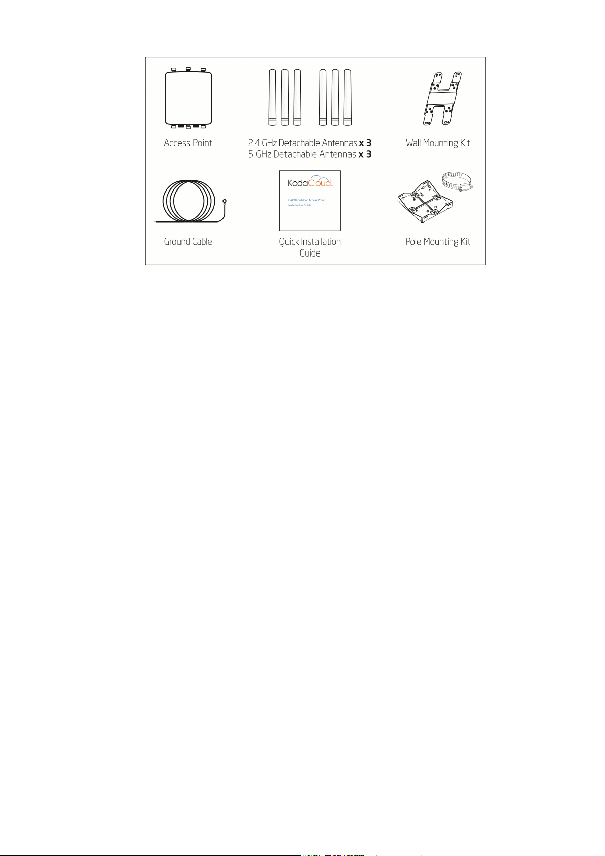
Package Contents
Step 1 - Connect the Access Point
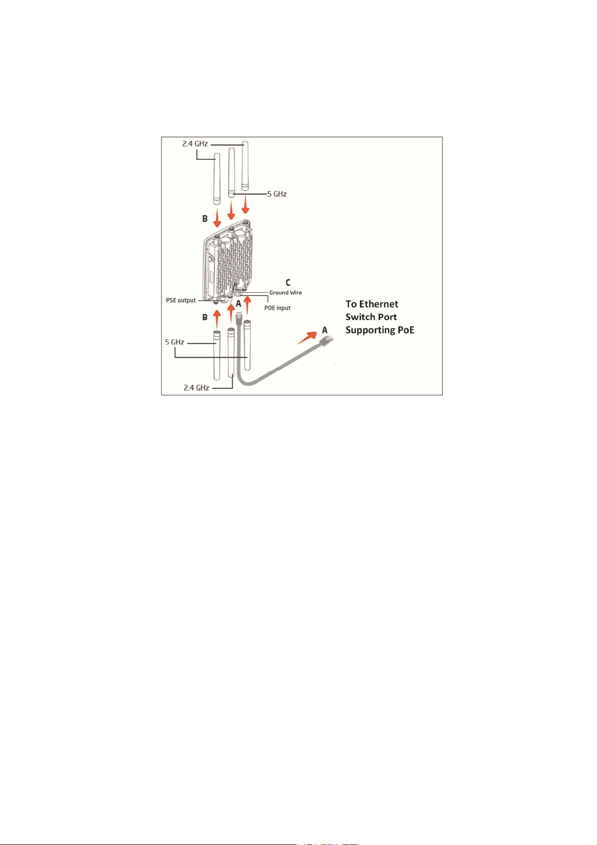
A Connect one end of the Ethernet cable to the LAN1 Port (PoE) of the access point and
the other end to the LAN + PoE (Power-over-Ethernet).
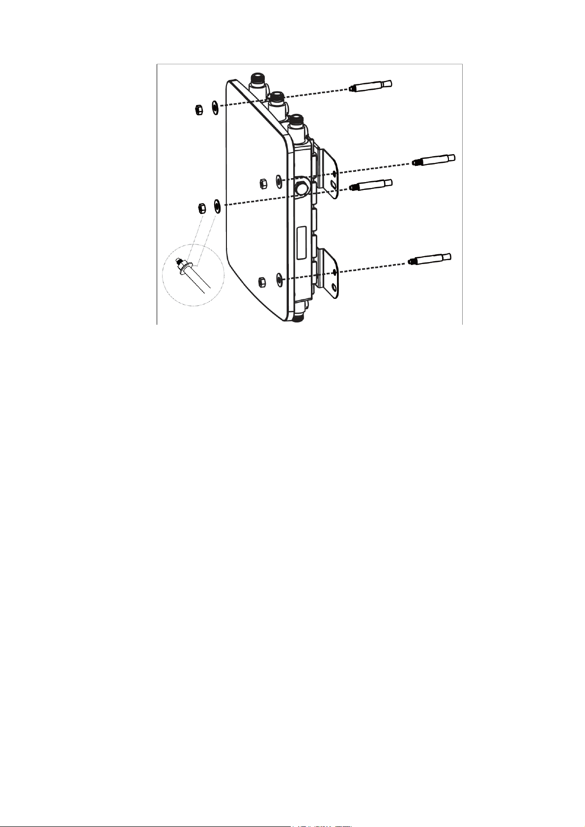
B Screw on the antennas (supplied separately) as shown in the following illustration.
C Connect the ground wire to the access point.
Note: The access point supports both IEEE 802.3at PoE (Power-over-Ethernet) supplied by a
switch, or using a PoE Injector. You may use either one as the power source. DO NOT
use both at the same time.
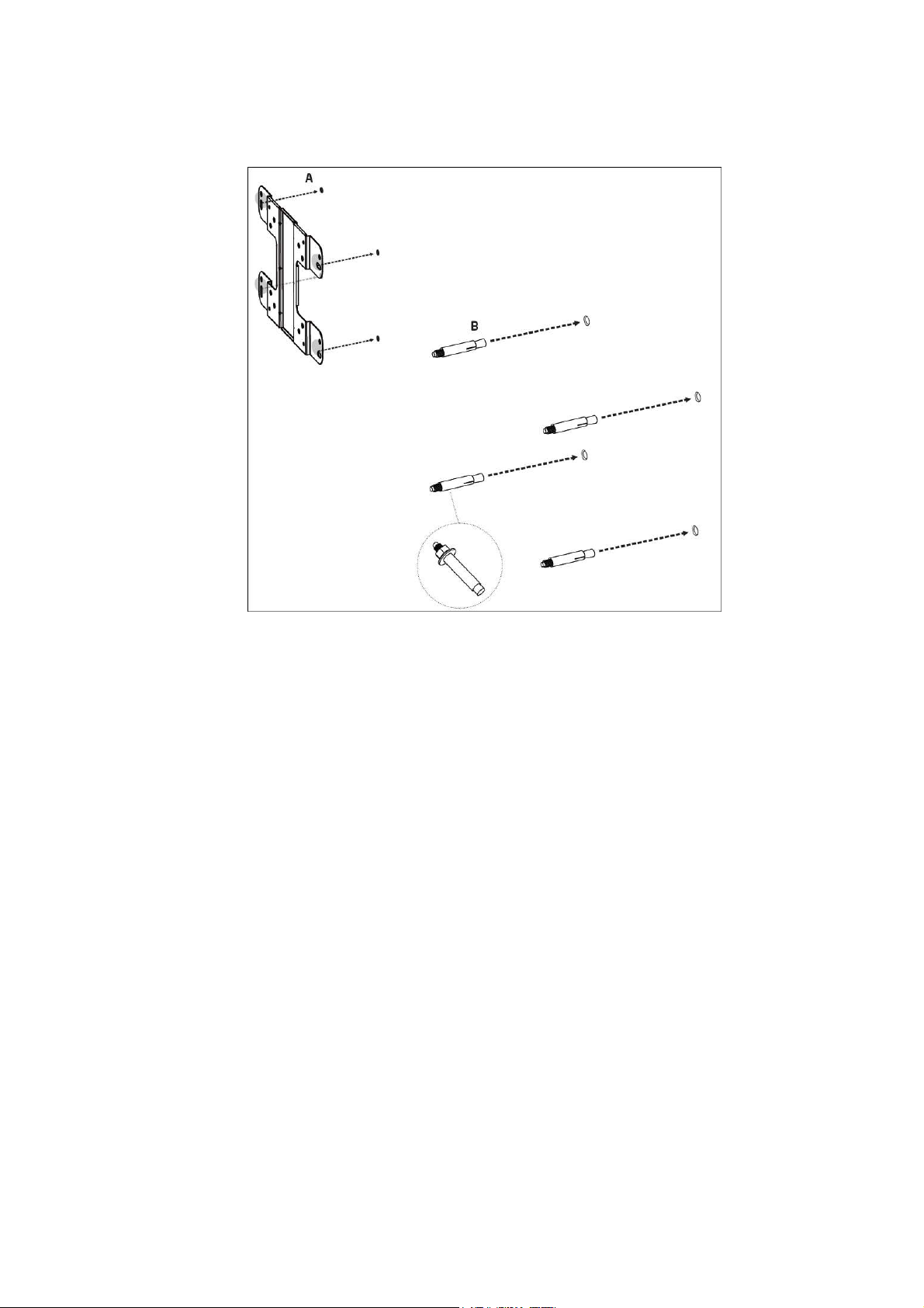
Step 2 – Mount the Access Point
Wall Mounting
A Determine where the AP is to be placed and mark location on the surface for the four
mounting holes. You may adjust the position with a level.
B Use the appropriate drill bit to drill four 8 mm diameter and 37 mm depth holes in the
markings and hammer the bolts into the openings.
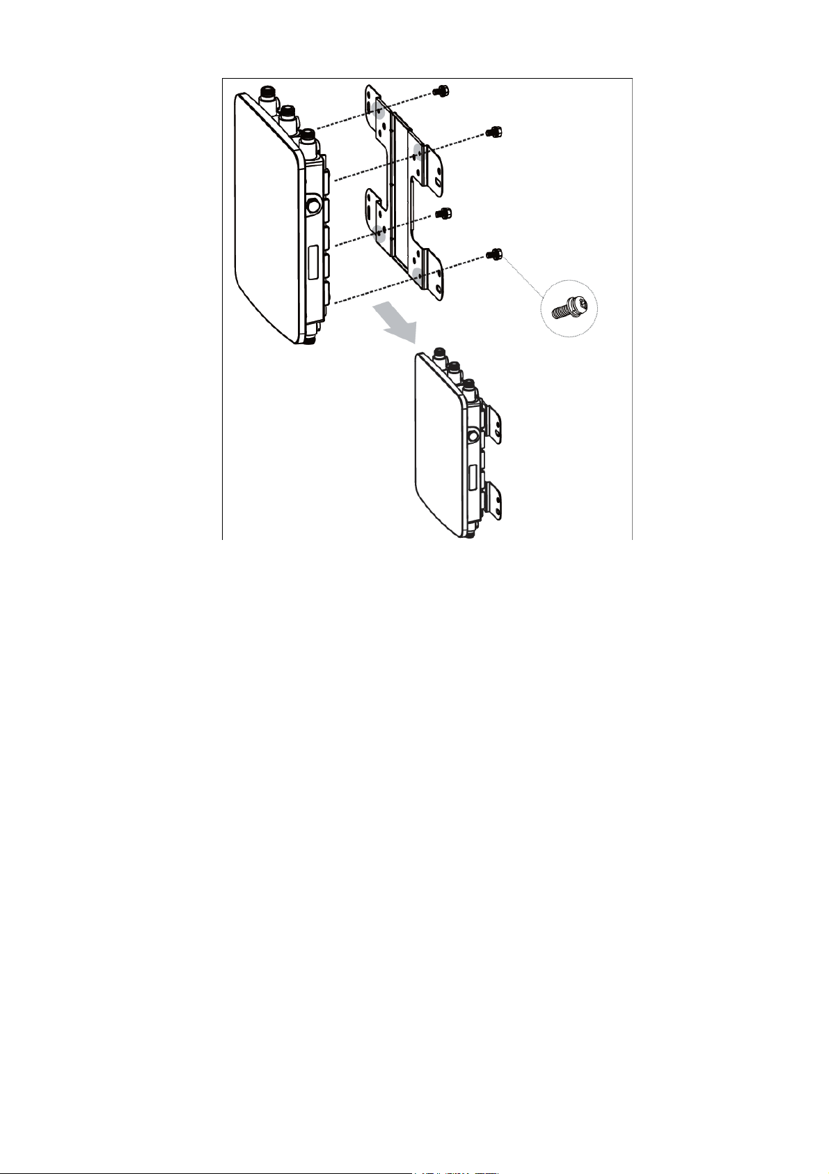
C Place the lock and flat washer on the round head screws and drive the screws to attach
mounting base to the back of the access point.
D Attach the device onto the wall by tightening the bolt’s flat washers and nuts to secure
the mounting base to the mounting surface. Connect the ground wire (not shown) to a
grounding point.

Pole Mounting
A Place the lock and flat washer on the round head screws and drive the screws to attach
the mounting base to the back of the access point.

B Determine which placement to be assembled. Drive the four round head screws to attach
the pole mount bracket to the mounting base.

C Thread the open end of the pole strap through the two tabs on the pole mount bracket.

D Determine where the AP is to be fastened. Lock and tighten pole strap to secure pole
mount bracket to the pole. Connect the ground wire (not shown) to a grounding point.

Step 3 - Verify connectivity
1 Power LED
Solid
Orange and a
ll other
Unit has just received power and has
2 Power LED Solid
Orange and a
ll other
Unit is starting up.
3 Blinking Green
A
ccess point
is negotiating a connection
4 Solid Green
Access point
is successfully
setup to be
LED LED Description
5 GHz
Green: 5 GHz radio
is active (off otherwise)
2.4 GHz
Green: 2.4 GHz radio is active (off otherwise)
LAN 2
Green: Ethernet Link on LAN2 Port (off otherwise)
LAN 1
Green: Ethernet Link on LAN1 Port (off otherwise)
Verify that the OAP30 access point is connected to your network with either the KodaCloud
website or the KodaCloud mobile device app.
Check the Power LED to determine whether the access point is operating correctly. The
access point is properly installed and connected to the KodaCloud management services when
the LED turns solid green after a few minutes.
When the access point is powered on, the Power LED should display the following sequence:
# Power LED Description
LEDs on
(for less than 10 seconds)
LEDs off
(for less than a few minutes)
(for less than a minute)
Note 1: The very first time the Access Point is connected, it will self-update so it will go
through this sequence twice
started booting
with KodaCloud management services in
the cloud.
managed by KodaCloud management
services in the cloud.

Note 2: See the Tips and Troubleshooting section if the access point does not reach Solid
Green. For a full description of LED Description visit the Support website
(http://KodaCloud.com/support).
Step 4 - Configure the Access Point
Use your mobile device or the KodaCloud website.
Website
Sign into your account at http://KodaCloud.com and follow the instructions in the KodaCloud
website to complete the process.
Mobile Device
Information about the mobile app is available at http://KodaCloud.com. The mobile device
app includes instructions for completing the process.
If you have any trouble, please contact support@kodacloud.com and we’ll be happy to help!

Tips and Troubleshooting
If your access point Power LED light is flashing orange and all other LEDs are off for over
10 minutes
The access point cannot connect to the KodaCloud management services. This usually occurs
when the unit cannot get an IP address from your network using DHCP and has switched to
Local Network Configuration mode.
While in this mode, the access point does not pass data through the LAN1 port and broadcasts
an SSID that contains a portion of the access point’s MAC address. You can use any Wi-Fi
enabled device to connect to this SSID and configure the network settings for this access point
using a web browser.
To connect to the access point using the Local Network Configuration interface:
1. Connect your Wi-Fi enabled device to the SSID in the form of “AP-XX:XX:XX” (where
X is a placeholder)). You are successfully connected when the Power LED on the
access point becomes solid red.
2. Use your web browser to navigate to http://192.168.100.1 (login using user: admin,
password: admin).
3. Follow the on-screen instructions
See the Support section (http://kodacloud.com/support) for information about Local Network
Configuration.
Note: Local Configuration mode only activates if the access point is in factory default
condition and has never connected to the KodaCloud management services in the cloud.
Learning More, Service, and Support
Online Resources
Our support website (http://kodacloud.com/support) contains links to online resources
available to help you get the most out of your access point.
Copyright and Trademark
Copyright © 2016 KodaCloud, Inc. All rights reserved. The contents of this Installation Guide
are the copyrighted and proprietary property of KodaCloud, Inc. Reproduction, distribution
or modification without the express, written permission of KodaCloud, Inc. is not permitted.
“Art2Wave” and “KodaCloud” are trademarks of KodaCloud, Inc. All other trademarks are the
property of their respective owners.

Open Source Code
Certain KodaCloud products include open source software code subject to the GNU General
Public License (GPL) and other Open Source Licenses. For more information, see:
http://KodaCloud.com/opensource
Legal Notice
EXCEPT FOR ANY WRITTEN EXPRESS WARRANTY WE MAY SEPARATELY OFFER TO YOU, AND TO
THE EXTENT PERMITTED BY LAW, THIS PRODUCT IS PROVIDED “AS IS” AND WE SPECIFICALLY
DISCLAIM ALL EXPRESS, STATUTORY AND IMPLIED WARRANTIES, INCLUDING, BUT NOT LIMITED
TO, WARRANTIES OF MERCHANTABILITY, FITNESS FOR A PARTICULAR PURPOSE, NONINFRINGEMENT AND AGAINST HIDDEN OR LATENT DEFECTS. IF WE CANNOT LAWFULLY
DISCLAIM STATUTORY OR IMPLIED WARRANTIES, THEN TO THE EXTENT PERMITTED BY LAW,
ALL SUCH WARRANTIES SHALL BE LIMITED IN DURATION TO THE DURATION OF ANY WRITTEN
EXPRESS WARRANTY WE MAY SEPARATELY OFFER TO YOU, AS APPLICABLE, AND TO REPAIR OR
REPLACEMENT SERVICE. SOME JURISDICTIONS DO NOT ALLOW LIMITATIONS ON HOW LONG A
STATUTORY OR IMPLIED WARRANTY LASTS, SO THE ABOVE LIMITATION MAY NOT APPLY TO
YOU. WE ARE NOT RESPONSIBLE FOR DIRECT, SPECIAL, INCIDENTAL OR CONSEQUENTIAL
DAMAGES RESULTING FROM ANY BREACH OF WARRANTY OR UNDER ANY OTHER LEGAL THEORY.
IN SOME JURISDICTIONS THE FOREGOING LIMITATION DOES NOT APPLY TO DEATH OR
PERSONAL INJURY CLAIMS, OR ANY STATUTORY LIABILITY FOR INTENTIONAL AND GROSS
NEGLIGENT ACTS AND/OR OMISSIONS, SO THE ABOVE EXCLUSION OR LIMITATION MAY NOT
APPLY TO YOU. SOME JURISDICTIONS DO NOT ALLOW THE EXCLUSION OR LIMITATION OF
DIRECT, INCIDENTAL OR CONSEQUENTIAL DAMAGES, SO THE ABOVE EXCLUSION OR LIMITATION
MAY NOT APPLY TO YOU.

OAP30 Specifications and Safety Guidelines
Specifications:
Frequency Bands: Programmable for different country regulations
Radio 1 – 2.400 to 2.484 GHz
Radio 2 - 5.150 – 5.250 GHz, 5.725 – 5.850 GHz
Standards: Radio 1 2.4G IEEE 802.11 b/g/n, Radio 2 5G IEEE 802.11 a/n/ac
Input voltage and current: 54VDC @ 1.2A
Interfaces:
RJ-45 for 10/100/1000 Gigabit Ethernet
2nd RJ45 port support 802.3af (15.4W) PSE
6 N-Type connector
Environmental Specifications:
Operating Temperature: -40℃ to 60℃
Storage Temperature: -40℃ to 70℃ (-40°F to 158°F)
Humidify: 5% ∼ 90% typical (non-condensing)
Antenna Specifications:
Antenna: N-type Dipole
Peak Gain: 4.5 dBi @ 2.4 GHz / 6 dBi @ 5 GHz
Caution:
Safety caution: The unit should be connected to PoE networks only, without routing to the
outside plant.
Regulatory Compliance Information
FCC
This equipment has been tested and found to comply with the limits for a Class B digital
device, pursuant to Part 15 of the FCC Rules. These limits are designed to provide reasonable
protection against harmful interference in a residential installation. This equipment
generates, uses and can radiate radio frequency energy and, if not installed and used in
accordance with the instructions, may cause harmful interference to radio communications.
However, there is no guarantee that interference will not occur in a particular installation. If
this equipment does cause harmful interference to radio or television reception, which can be

determined by turning the equipment off and on, the user is encouraged to try to correct the
interference by one of the following measures:
Reorient or relocate the receiving antenna
Increase the separation between the equipment and receiver
Connect the equipment into an outlet on a circuit different from that to which the
receiver is connected
Consult the dealer or an experienced radio/TV technician for help
FCC Caution: Any changes or modifications not expressly approved by the party responsible
for compliance could void the user's authority to operate this equipment. See 47 CFR 1.80.
This device complies with Part 15 of the FCC Rules. Operation is subject to the following two
conditions: (1) This device may not cause harmful interference, and (2) this device must
accept any interference received, including interference that may cause undesired operation.
IMPORTANT NOTE:
Radiation Exposure Statement:
This equipment complies with FCC radiation exposure limits set forth for an uncontrolled
environment. This equipment should be installed and operated with minimum distance 31cm
between the radiator and your body.
This transmitter must not be co-located or operating in conjunction with any other antenna or
transmitter.
There is no Country Code selection capability for USA Part # OAP30-UC.
Professional installation instruction
1. Installation personal
This product is designed for specific application and needs to be installed by a qualified
personal who has RF and related rule knowledge. The general user shall not attempt to install
or change the setting.
2. Installation location
The product shall be installed at a location where the radiating antenna can be kept 31cm
from nearby person in normal operation condition to meet regulatory RF exposure
requirement.
3. External antenna

Use only the antennas which have been approved by the applicant. The non-approved
antenna(s) may produce unwanted spurious or excessive RF transmitting power which may
lead to the violation of FCC limit and is prohibited.
4. Installation procedure
Please refer to user’s manual for the detail.
5. Warning
Please carefully select the installation position and make sure that the final output power
does not exceed the limit set force in relevant rules. The violation of the rule could lead to
serious federal penalty.
Instructions d'installation professionnelle
1. Installation
Ce produit est destine a un usage specifique et doit etre installe par un personnel qualifie
maitrisant les radiofrequences et les regles s'y rapportant. L'installation et les reglages ne
doivent pas etre modifies par l'utilisateur final.
2. Emplacement d'installation
En usage normal, afin de respecter les exigences reglementaires concernant l'exposition aux
radiofrequences, ce produit doit etre installe de facon a respecter une distance de 31 cm
entre l'antenne emettrice et les personnes.
3. Antenn externe.
Utiliser uniiquement les antennes approuvees par le fabricant. L'utilisation d'autres antennes
peut conduire a un niveau de rayonnement essentiel ou non essentiel depassant les niveaux
limites definis par FCC, ce qui est interdit.
4. Procedure d'installation
Consulter le manuel d'utilisation.
5. Avertissement
Choisir avec soin la position d'installation et s'assurer que la puissance de sortie ne depasse
pas les limites en vigueur. La violation de cette regle peut conduire a de serieuses penalites
federales.

Industry Canada
This device complies with Industry Canada licence-exempt RSS standard(s). Operation is
subject to the following two conditions: (1) this device may not cause interference, and (2)
this device must accept any interference, including interference that may cause undesired
operation of the device.
Cet appareil est conforme aux CNR exemptes de licence d'Industrie Canada. Son
fonctionnement est soumis aux deux conditions suivantes: (1) Ce dispositif ne peut causer
d'interférences; et(2) Ce dispositif doit accepter toute interférence, y compris les
interférences qui peuvent causer un mauvais fonctionnement de l'appareil.
Caution:
(i) The device for operation in the band 5150-5250 MHz is only for indoor use to reduce the
potential for harmful interference to co-channel mobile satellite systems;
(ii) the maximum antenna gain permitted for devices in the bands 5250-5350 MHz and 54705725 MHz shall comply with the e.i.r.p. limit; and
(iii) the maximum antenna gain permitted for devices in the band 5725-5825 MHz shall comply
with the e.i.r.p. limits specified for point-to-point and non point-to-point operation as
appropriate.
(iv) Users should also be advised that high-power radars are allocated as primary users (i.e.
priority users) of the bands 5250-5350 MHz and 5650-5850 MHz and that these radars could
cause interference and/or damage to LE-LAN devices.
Avertissement:
(i) Les dispositifs fonctionnant dans la bande 5150-5250 MHz sont réservés uniquement pour
une utilisation à l’intérieur afin de réduire les risques de brouillage préjudiciable aux
systèmes de satellites mobiles utilisant les mêmes canaux;
(ii) le gain maximal d’antenne permis pour les dispositifs utilisant les bandes 5 250-5 350 MHz
et 5 470-5 725 MHz doit se conformer à la limite de p.i.r.e.;
(iii) le gain maximal d’antenne permis (pour les dispositifs utilisant la bande 5 725-5 825 MHz)
doit se conformer à la limite de p.i.r.e. spécifiée pour l’exploitation point à point et non
point à point, selon le cas.
(iv) De plus, les utilisateurs devraient aussi être avisés que les utilisateurs de radars de haute
puissance sont désignés utilisateurs principaux (c.-à-d., qu’ils ont la priorité) pour les bandes
5 250-5 350 MHz et 5 650-5 850 MHz et que ces radars pourraient causer du brouillage et/ou
des dommages aux dispositifs LAN-EL.
Radiation Exposure Statement:

This equipment complies with IC radiation exposure limits set forth for an uncontrolled
environment. This equipment should be installed and operated
between the radiator & your body.
Cet équipement est conforme aux limites d'exposition aux rayonnements IC établies pour un
environnement non contrôlé. Cet équipement doit être install
de distance entre la source de rayonnement et votre corps.
product is designed for specific application and needs to be installed by a qualified
personal who has RF and related rule knowledge. The general user shall not attempt to install
lled at a location where the radiating antenna can be kept
from nearby person in normal operation condition to meet regulatory RF exposure
Use only the antennas which have been approved by the applicant. The non
antenna(s) may produce unwanted spurious or excessive RF transmitting power which may
lead to the violation of ISED limit and is prohibited.
Please refer to user’s manual for the detail.
t the installation position and make sure that the final output power
does not exceed the limit set force in relevant rules. The violation of the rule could lead to
Déclaration d'exposition aux radiations:
with minimum distance 35 cm
35 cm
Professional installation instruction
1. Installation personal
This
or change the setting.
2. Installation location
The product shall be insta
requirement.
3. External antenna
4. Installation procedure
5. Warning
Please carefully selec
é et utilisé avec un minimum de
ICES-003 issue 5 (2013/08/01)
CAN ICES-3(*)/NMB-3(*)
[*] = Class A or B
35 cm
-approved
serious federal penalty.
Instructions d'installation professionnelle

1. Installation
Type Gain Brand
Manufacturer
Dipole(2.4G)
4.5dBi
Senao
Senao Networks, Inc.
Dipole(5G)
6.0 dBi
Senao
Senao Networks, Inc.
Ce produit est destine a un usage specifique et doit etre installe par un personnel qualifie
maitrisant les radiofrequences et les regles s'y rapportant. L'installation et les reglages ne
doivent pas etre modifies par l'utilisateur final.
2. Emplacement d'installation
En usage normal, afin de respecter les exigences reglementaires concernant l'exposition aux
radiofrequences, ce produit doit etre installe de facon a respecter une distance de 35 cm
entre l'antenne emettrice et les personnes.
3. Antenn externe.
Utiliser uniiquement les antennes approuvees par le fabricant. L'utilisation d'autres antennes
peut conduire a un niveau de rayonnement essentiel ou non essentiel depassant les niveaux
limites definis par ISED, ce qui est interdit.
4. Procedure d'installation
Consulter le manuel d'utilisation.
5. Avertissement
Choisir avec soin la position d'installation et s'assurer que la puissance de sortie ne depasse
pas les limites en vigueur. La violation de cette regle peut conduire a de serieuses penalites
federales.
DETACHABLE ANTENNA USAGE
This radio transmitter (IC: 12659A-OAP30 / Model: OAP30) has been approved by ISED to
operate with the antenna type listed below with maximum permissible gain indicated.
Antenna types not included in this list, having a gain greater than the maximum gain
indicated for that type, are strictly prohibited for use with this device.
Le présent émetteur radio IC: 12659A-OAP30 / Model: OAP30pprouvé par ISED pour
fonctionner avec les types d'antenne énumérés ci-dessous et ayant un gain admissible
maximal. Les types d'antenne non inclus dans cette liste, et dont le gain est supérieur au gain
maximal indiqué, sont strictement interdits pour l'exploitation de l'émetteur.
Approved antenna(s) list
 Loading...