

Koch Ultravac 250 Owner's Manual

Ultravac® 250
Vacuum Chamber Packaging Machine
860108 Revision Q
Date 01/2009

TABLE OF CONTENTS
MAIN: 816-753-2150
TOLL FREE: 800-777-5624
INTERNET: kochequipment.com
E-MAIL: info@kochequipment.com
General ...............................................III
Specifications ....................................... IV
SAFETY
Personal Safety ....................................1.1
Food Safety ........................................1.2
General Safety Guidelines ....................1.2
STARTUP
Unpacking ..........................................2.1
Power Requirements .............................2.1
Grounding Instructions.........................2.1
Vacuum Pump .................................... 2.2
Gas Flush Connection ........................ 2.3
Air-Assist Connection .......................... 2.3
Checking Vacuum Pump Rotation ........ 2.3
OPERATION
Placement of Product ...........................3.1
Operation with Analog Control Panel ... 3.2
Operation with Digital Control Panel .... 3.3
Operator Menu on Digital Panel .......... 3.4
Selecting a New Program .................... 3.6
Sealing with Air-Assist ......................... 3.7
Gas Flush Option ............................... 3.7
Double Seam Seal Option .................. 3.7
MAINTENANCE
Prior to Cleaning .................................4.1
Cleaning Recommendations .................4.1
Vacuum Pump Maintenance ................ 4.2
Seal Bar Maintenance ......................... 4.2
Reading the Indicators ........................ 4.3
Troubleshooting ................................. 4.4
Supervisor Menu on Digital Panel ........ 4.6
Opening Chamber Machine ............... 4.11
Changing Vacuum Pump Oil .............. 4.11
Replacing Power Cord .......................4.12
Replacing Potentiometer ..................... 4.12
Maintenance Log .............................. 4.13
Service Log .......................................4.13
SCHEMATICS
Designation and Function of Controls....5.1
110 Volt, Single Phase ......................... 5.2
220 Volt, Single Phase ........................ 5.3
110 Volt, Double Seal Bar ................... 5.4
220 Volt, Double Seal Bar ................... 5.5
Non-Gas Flush Pneumatic Diagram ..... 5.6
Gas Flush Pneumatic Diagram ............. 5.7
PARTS
Recommended Spare Parts ...................6.1
Pump and Chassis .............................. 6.2
Seal Bar ............................................ 6.4
Lid and Hinge System ......................... 6.6
Gas Flush Components....................... 6.8
Analog Control Panel ........................6.10
Digital Control Panel .........................6.12
Mebner Valve ....................................6.13
Miscellaneous Machine Parts ..............6.14
Pump Filter Option ............................6.15
REFERENCE MANUALS
R5 Series Vacuum Pumps .....................7.1
INDEX .............................................. 8.1
860108•Q
INTRODUCTION •
PAGE I
Specifications
MAIN: 816-753-2150
TOLL FREE: 800-777-5624
INTERNET: kochequipment.com
E-MAIL: info@kochequipment.com
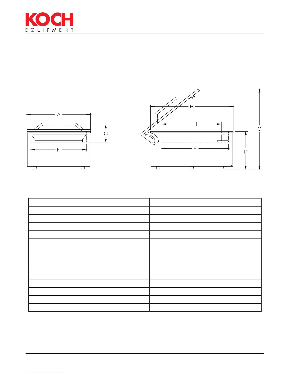
Figure 0.1
Length (A): 483mm (19-in.)
Width (B): 625mm (24.625-in.)
Maximum Height (C): 826mm (32.5-in.)
Working Height (D): 365mm (14.375-in.)
Seal Bar Length: 406mm (16-in.)
Chamber Length (E): 505mm (19.875-in.)
Chamber Width (F): 422mm (16.625-in.)
Chamber Height (G): 171mm (6.75-in.)
Between Seal Bar and Back of Chamber (H): 451mm (17.75-in.)
Between Seal Bars (double seal bar option): 416mm (16.375-in.)
Vacuum Pump: 25m
3
/h (15cfm) 0.95kW (1.25-hp)
Net Weight: 81-kg, 178-lbs.
Electrical Connection: See Power Requirements in Section 2
Capacity: 20-30 seconds per cycle
860108•Q
INTRODUCTION •
PAGE IV
MAIN: 816-753-2150
WARNING
WARNING
CAUTION
CAUTION
TOLL FREE: 800-777-5624
INTERNET: kochequipment.com
E-MAIL: info@kochequipment.com
SAFETY
Personal Safety
The procedures and guidelines herein must be followed precisely to avoid problems that can
result in property damage, personal injury, or death. If you have any questions related to
this information, please contact Koch Equipment Services Inc. at (800) 777-5624.
DANGER
Disconnect and lockout power before servicing machine or cleaning. Do not remove panels
unless power has been disconnected, locked out, and tagged out at risk of electric shock
hazard.
Hazardous voltage.
DANGER
Improper connection of the equipment-grounding conductor can result in a risk of electric
shock.
WARNING
Read and understand owner’s manual before using this machine. Failure to follow operating
instructions could result in personal injury or damage to equipment.
WARNING
Do not use a gas with an oxygen content greater than 22% with gas flush option.
CAUTION
Only let the front foot of the chassis hang over the edge of the table.
CAUTION
Do not get the cleaning agents in eyes, on skin, or on clothing. Always wear rubber gloves,
goggles, and protective clothing when contact is likely. Consult product manufacturer for
specific details.
Hazardous voltage.
Explosion hazard.
Tip over hazard.
Cleaning agents.
Signal words used in classification of potential hazards are defined as follows:
DANGER: Indicates an imminently hazardous situation, which, if not avoided, may result in death or
serious injury.
WARNING: Indicates a potentially hazardous situation, which, if not avoided, could result in death or
serious injury.
CAUTION: Indicates a potentially hazardous situation, which, if not avoided, may result in minor or
moderate injury. Caution also indicates actions that may cause property damage.
860108•Q
SAFETY •
P A G E 1.1

MAIN: 816-753-2150
TOLL FREE: 800-777-5624
INTERNET: kochequipment.com
E-MAIL: info@kochequipment.com
Food Safety
Food Packaging
While this machine is often used for food packaging and vacuum cooking, there are
inherent risks associated with this packaging technique that could cause serious illness
or death to the consumer of the food product. If you are using this machine for a food
application, you must consult with a reputable food technologist or specialist in vacuum/
modified atmosphere packaging (M.A.P.) to review the safety of your application.
Gas Flush
In order to ensure proper shelf life of the food product packaged in this machine, you
must contact a reputable food technologist or specialist in vacuum/modified atmosphere
packaging (M.A.P.) to review and develop the appropriate gas mixture for your package,
and you must perform quality control and gas analysis on your finished M.A.P. packages.
General Safety Guidelines
Obvious safety guidelines should be observed.
¾ Be sure to turn off power to your packaging machine before any maintenance work is
performed.
¾ Follow approved Lockout/Tagout procedures.
¾ Place machine on a flat, stable surface.
¾ Do not place tools, parts, or other objects on or inside machine while operating.
860108•Q
SAFETY •
P A G E 1.2

MAIN: 816-753-2150
TOLL FREE: 800-777-5624
INTERNET: kochequipment.com
E-MAIL: info@kochequipment.com
STARTUP
Unpacking
1. Carefully remove crate from the skid.
2. Remove machine from skid.
3. Wipe down outside of the machine.
Power Requirements
The owner must supply the correct single phase power source in accordance with the
National Electric Code. The machine is rated at 110 volt, 60 Hz, 15 amps; or 220 volt, 50
Hz, 8 amp. Do not use an extension cord to connect the machine to the wall outlet.
Grounding Instructions
The Ultravac® 250 must be grounded. In the event of malfunction or breakdown, grounding
provides a path of least resistance for electric current to reduce the risk of electric shock.
The unit is equipped with a equipment-grounding conductor cord and a grounding plug.
The plug must be plugged into an appropriate outlet that is properly installed and grounded
in accordance with all local codes and ordinances.
DANGER
Improper connection of the equipment-grounding conductor can result in a risk of electric
shock.
The equipment-grounding conductor outer surface is green with or without yellow
stripes. If repair or replacement of the cord or plug is necessary, do not connect the
equipment-grounding conductor to a live terminal. Check with a qualified electrician or
Koch Equipment Services Inc. technician if the grounding instructions are not completely
understood, or if there is doubt as to whether the unit is properly grounded. Do not modify
the plug provided with the unit – if it will not fit the outlet; have a proper outlet installed by
a qualified electrician.
Hazardous voltage.
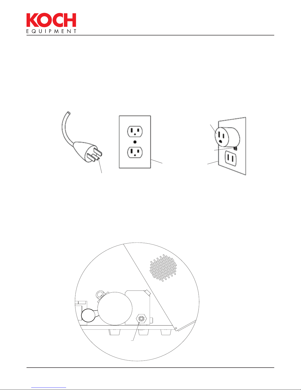
For 110 Volt Units
This unit is for use on a nominal 110V circuit, and has a factory equipped grounding plug
(see Figure 2.2A on page 2.2). A temporary adaptor (see Figure 2.2C on page 2.2), may
be used to connect this plug to a two-pole receptacle (see Figure 2.2C on page 2.2) if a
properly grounded outlet is not available. The temporary adaptor should be used only until
a properly grounded outlet (see Figure 2.2B on page 2.2) can be installed by a qualified
electrician. The green rigid ear extending from the adaptor must be held in place by the
metal screw on a properly grounded outlet box cover.
860108•Q
STARTUP •
PAGE 2.1
MAIN: 816-753-2150
TOLL FREE: 800-777-5624
INTERNET: kochequipment.com
E-MAIL: info@kochequipment.com
Grounding Instructions
For 220 Volt Units
This unit is for use on a nominal circuit having a rating more than 110V; or is rated more
than 15 amps and used on a nominal 110V circuit, and has a factory equipped grounding
plug. No adapter should be used with this unit. If the unit must be reconnected for use on
a different type of electric circuit, the reconnection should be made by qualified service
personnel; and after the reconnection, the appliance should comply with all local codes and
ordinances.
Temporary Adaptor
Metal Screw
Cover of Grounded
Outlet Box
Grounding Pin
A
B
C
Figure 2.1
Vacuum Pump
It is essential to check the oil level daily and to change the oil after every 500 hours of
operation. Read the oil level with the machine turned off. Oil may be added until the level
reaches the MAX level shown in the sight glass on the pump. Refer to the pump manual
supplied with the machine for details on changing the oil.
860108•Q
MAX
MIN
OIL SIGHT HOLE
STARTUP •
Figure 2.2
PAGE 2.2

MAIN: 816-753-2150
TOLL FREE: 800-777-5624
INTERNET: kochequipment.com
E-MAIL: info@kochequipment.com
Gas Flush Connection
The owner must supply a suitable regulator with a range of 0 to 60 p.s.i. We recommend
using food-grade flexible hose with a 1/4-in. I.D. and a maximum length of 15-ft. Maximum
regulator pressure is 15 p.s.i.
Air-Assist Connection
The machine is equipped with a regulator for air-assisted sealing. The hose barb will
accept 1/4-in. I.D. hose. The recommended air supply is 75 p.s.i. at 6 c.f.m. The maximum
regulator setting is 40 p.s.i.
Checking Vacuum Pump Rotation
Caution: Check oil level of pump before starting pump (please refer to pump manual).
To check the direction of the pump rotation, briefly engage the “POWER ON” switch and
observe the motor fan at the end of the pump. The fan should rotate as indicated by the
arrow on the fan cover. To correct the rotation, switch any two phases in the plug.
860108•Q
STARTUP •
PAGE 2.3

MAIN: 816-753-2150
TOLL FREE: 800-777-5624
INTERNET: kochequipment.com
E-MAIL: info@kochequipment.com
OPERATION
Placement of Product
For best sealing results, it is important to:
Check the pump oil level daily.
•
• Select a pouch that fits the product.
• Carefully load the product into the pouch.
• Keep the product and the product residue away from the seal area of the pouch.
• Place the product as far into the pouch as possible.
• Maintain an equal amount of the product above and below the seal bar (see figure 3.1,
below on use of filler plates).
Use Filler Plates for raising the height of the product.
•
• Lay the pouch flat on the seal area, keeping the pouch free of wrinkles.
• Place the pouch so that the open end is inside the chamber when the lid is closed.
PRODUCT HALF HEIGHT
EVEN WITH TOP OF
SEAL BAR
Figure 3.1
860108•Q
OPERATION •
PAGE 3.1
MAIN: 816-753-2150
TOLL FREE: 800-777-5624
INTERNET: kochequipment.com
E-MAIL: info@kochequipment.com
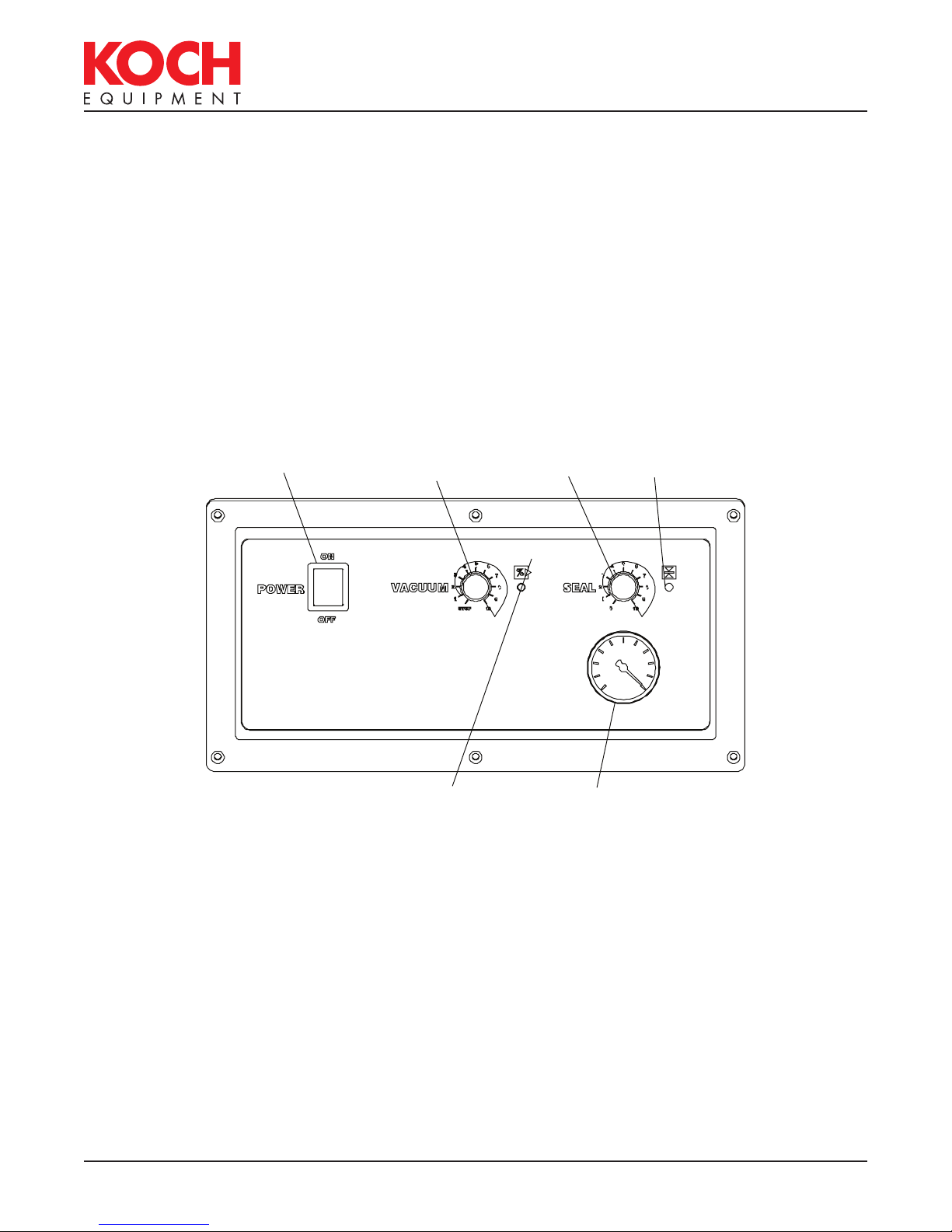
Operation with Analog Control Panel
The analog control panel is shown below, figure 3.2.
The range for timed vacuum is 0 to 55 seconds and is controlled by the Vacuum
Potentiometer. We suggest an initial setting of “3” on the dial.
Seal impulse is the length of time the seal bar is turned on and can range from 0 to
2 seconds. The impulse time is controlled by the Seal Potentiometer. Koch Equipment
recommends an initial setting of “6” on the potentiometer. This setting will vary according
to the thickness of the pouch. Thinner pouches will require a lower setting while thicker
pouches will require a higher setting.
Experiment with both settings to achieve the best results.
Figure 3.2
POWER SWITCH
VA CUUM
POTENTIOMETER
VACUUM LIGHT
(GREEN)
SEAL
POTENTIOMETER
VACUUM
INDICATOR
SEAL LIGHT
(RED)
860108•Q
OPERATION •
PAGE 3.2

MAIN: 816-753-2150
TOLL FREE: 800-777-5624
INTERNET: kochequipment.com
E-MAIL: info@kochequipment.com
Operation with Digital Control Panel
The digital control panel allows the user more options than the standard control panel. The
embedded microprocessor controls each sequence of the packaging operation. Settings for
the vacuum, gas, and sealing are entered as parameters through the keypad. This allows
the user to custom program every step of the packaging process. The precise vacuum
and gas pressures are controlled by a pressure based sensor. The vacuum pressure, gas
pressure, and seal time are displayed on a large 16-character LCD backlit readout, which
is easily readable in all lighting conditions. As each sequence is performed, the real-time
pressure level or cycle time is displayed.
The digital front panel can save up to 100 pre-programmed routines, which can be
retrieved at any time for specific packaging applications. With the supervisor security feature
turned on, these programs cannot be inadvertently changed.
The VACPLUS option allows the operator to run the pump from 0 to 20 seconds after the set
vacuum level is achieved.
The Gas Flush option allows the operator to introduce an inert gas into the chamber after
the vacuum stage. This option can be used as a filler to prevent crushing of the product
after sealing, as a means to prolong shelf life or as a means to maintain desirable product
appearance.
The digital front panel has an auto stop, which will automatically seal if the preset vacuum is
not reached. This feature decreases the cycle time and optimizes the vacuum level of each
product.
The digital front panel, which includes the keypad, illuminated display, and microprocessor,
uses sealed components and is conformal coated in a moisture-proof coating. The digital
front panel meets or exceeds the requirements of NEMA 4. The front of the digital display is
sealed and flush for easy cleaning.
The digital control has both pulsed vacuum and pulsed venting options for fragile product.
The digital control has a maintenance screen for testing valves and a special loop option for
multiple vacuum/gas cycles before sealing.
Figure 3.3
860108•Q
OPERATION •
PAGE 3.3
MAIN: 816-753-2150
TOLL FREE: 800-777-5624
INTERNET: kochequipment.com
E-MAIL: info@kochequipment.com
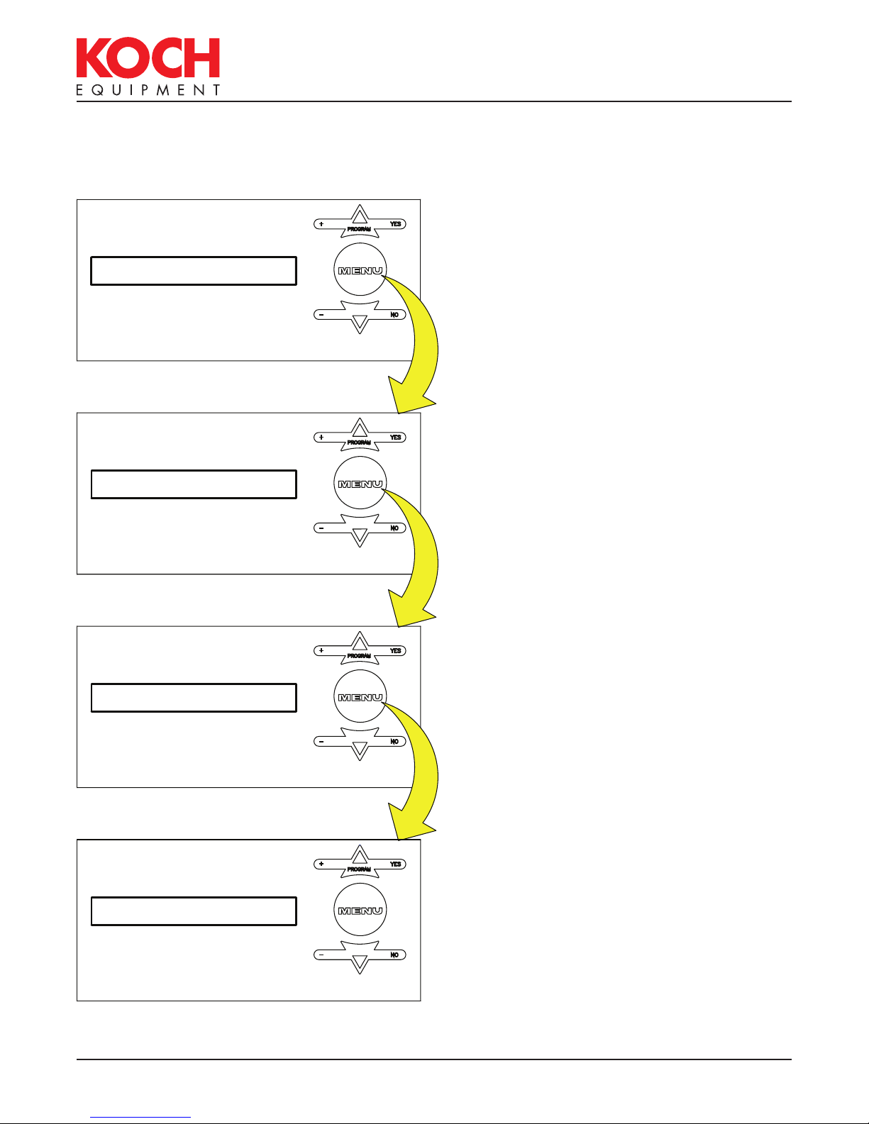
Operator Menu on Digital Panel
NOTE: if the supervisor has set security on, these settings cannot be changed.
RUNNING PROG: 1
VACUUM: 98
+
PROGRAM
YES
machine starts up, the last program that was
run will be the current program shown in
the window. To set the operating parameters
for the program shown press the MENU key.
This is the Main Menu screen. When the
-
+
PROGRAM
NO
YES
VACUUM is set to % vacuum using the UP
and DOWN Arrow Keys.
The range is 30% to 99%.
Press the MENU key.
-
NO
VACPLUS: 4.0
SEAL: 1.2
Figure 3.4
+
PROGRAM
YES
A setting greater than 0 allows the pump
to continue evacuating the chamber (for
the specified number of seconds) after the
pressure in the chamber has reached the %
VACPLUS may be set from 0 to 20 seconds.
-
NO
vacuum set in the vacuum menu.
Press the MENU key.
The SEAL setting is in seconds. Use the UP
+
PROGRAM
YES
and DOWN arrow keys to change the seal
time. The range is 0 to 2 seconds.
Press the MENU key.
-
NO
860108•Q
OPERATION •
PAGE 3.4
INTERNET: kochequipment.com
WARNING
E-MAIL: info@kochequipment.com
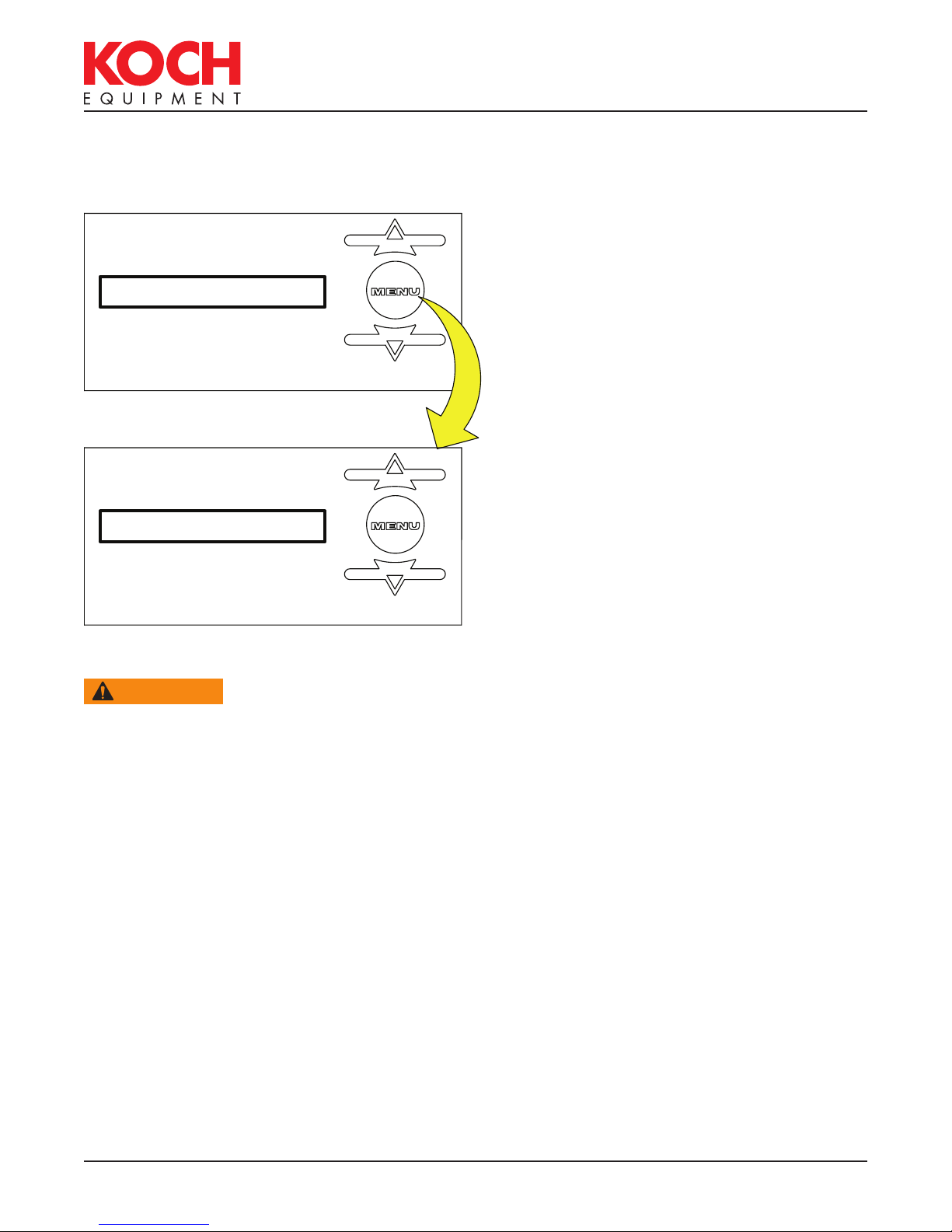
Operator Menu on Digital Panel (continued)
MAIN: 816-753-2150
TOLL FREE: 800-777-5624
GAS: YES
GAS: 75
Figure 3.5
+
PROGRAM
YES
If the machine is equipped with the gas
option, it can be turned on or off by pressing
the UP or DOWN arrow keys.
Press the MENU key.
-
NO
Gas is set to % gas using the UP and DOWN
+
PROGRAM
YES
Arrow Keys. This value also corresponds to
the vacuum reading inside the chamber. It
is recommended to use pulse vent when gas
flushing to a low % vacuum. The range is
-
NO
98% to 30%.
Press the MENU key.
WARNING
Explosion hazard.
Do not use a gas with an oxygen content greater than 22% with gas flush option.
860108•Q
OPERATION •
PAGE 3.5
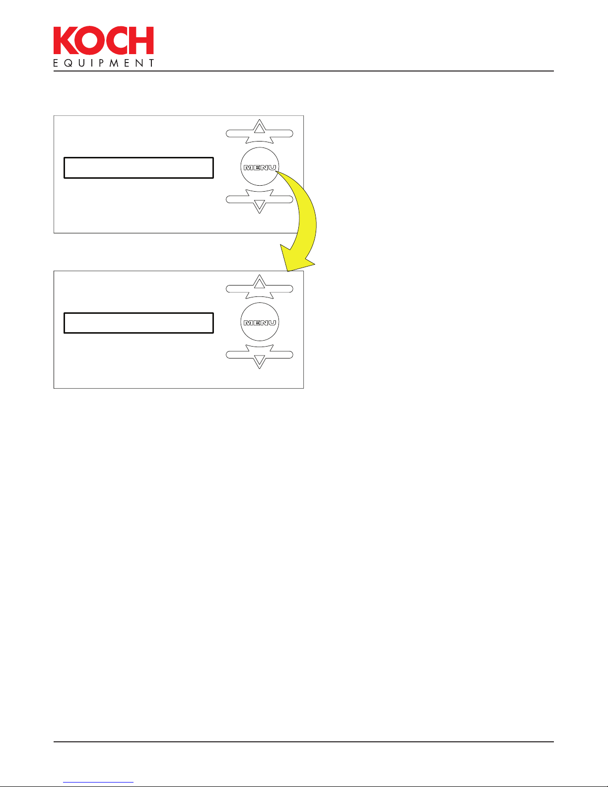
Selecting a New Program
+
PROGRAM
MAIN: 816-753-2150
TOLL FREE: 800-777-5624
INTERNET: kochequipment.com
E-MAIL: info@kochequipment.com
From the Main Menu, use the UP and
YES
DOWN Arrow Keys to select a new program.
RUNNING PROG: 1
ENTER PROGAM: 2
Figure 3.6
Press the UP Arrow to switch to program 2
(or any of the ten programs.)
-
NO
New parameters may be set for vacuum,
+
PROGRAM
YES
seal time and gas for program 2 (following
the procedure described in the previous
example) or simply close the lid on the
machine and run program 2.
-
NO
860108•Q
OPERATION •
PAGE 3.6

MAIN: 816-753-2150
WARNING
TOLL FREE: 800-777-5624
INTERNET: kochequipment.com
E-MAIL: info@kochequipment.com
Sealing with Air-Assist
All machines are equipped with regulators for air-assisted sealing. Set the air pressure
regulator to 20 p.s.i. increasing to a maximum of 40 p.s.i. While a good seal can be
obtained without air-assist, use air-assist when:
• Gas back-flushing above average pressure.
• Using shrink pouches.
• Packaging a product that easily contaminates the seal area of the pouch.
• Trying to overlap pouches.
• Wrinkles cannot be avoided in the seal area.
•
Using the Double Seam Seal Option.
Gas Flush Option
Gas flushing is the introduction of an inert gas into the chamber after the vacuum stage
is finished. Gas can be used as a filler to prevent crushing of the product after sealing, as
a means to prolong shelf life or as a means to maintain desirable product appearance.
Commonly used gasses include nitrogen, carbon dioxide, or a mixture of both. Consult your
local gas supplier to select the proper gas for your product.
WARNING
Explosion hazard.
Do not use a gas with an oxygen content greater than 22% with gas flush option.
Double Seam Seal Option
All machines are equipped with standard seal bars having a single seal element per seal
bar. The double seam seal bars have two seal elements per seal bar. We recommend using
air-assisted sealing with this option to achieve best results.
860108•Q
OPERATION •
PAGE 3.7

MAIN: 816-753-2150
TOLL FREE: 800-777-5624
INTERNET: kochequipment.com
E-MAIL: info@kochequipment.com
THIS PAGE LEFT BLANK INTENTIONALLY.
860108•Q
OPERATION •
PAGE 3.8
MAIN: 816-753-2150
CAUTION
TOLL FREE: 800-777-5624
INTERNET: kochequipment.com
E-MAIL: info@kochequipment.com
MAINTENANCE
Prior to Cleaning
Every environment and application is different; therefore, Koch Equipment LLC cannot
provide cleaning instructions to guarantee microbiological sanitation. Koch Equipment
requests that the owner of this machine consult with sanitation experts to review the
unit working in their particular environment to develop a robust cleaning schedule and
methodology, followed by bacterial testing to ensure satisfactory cleaning procedures are
followed.
Cleaning Recommendations
Before cleaning the machine, turn power off; disconnect the main power, and lockout the
connection.
DANGER
Disconnect and lockout power before servicing machine or cleaning. Do not remove panels
unless power has been disconnected and locked out at risk of electric shock hazard.
Check with the detergent and sanitizer manufacturers that their products are compatible
with the listed materials.
CAUTION
Do not get the cleaning agents in eyes, on skin, or on clothing. Always wear rubber gloves,
goggles, and protective clothing when contact is likely. Consult product manufacturer for
specific details.
Never hose down the machine. Damage caused by hosing or high pressure washing is not
covered under warranty.
1. Filler Plates: Remove filler plates. The filler plates are made from polyethylene. Clean,
sanitize, and dry. High pressure water spray can be used on the filler plates.
2. Lid and Backup Strip: The lid is constructed of acrylic. Use only nonabrasive soap and
water. Do not use window sprays or kitchen scouring compounds. The backup strip is
made of silicone. Clean, sanitize, and dry.
3. Seal Bars: Remove the seal bars by first lifting them up off of the guide rods. Remove
the wire connectors from the adapter clips on the seal bar and remove the seal bar from
the machine. The seal bars are made of aluminum and phenolic. Clean, sanitize, and
dry.
4. Chamber and Base: The chamber is made of 304 stainless steel and the base is made
from polyurethane. Clean, sanitize, and dry, including under the seal bar bladder (not
removable).
5. Clean under the machine.
6. Reinstall the seal bar.
7. Use bacteriological testing to insure cleaning process.
Hazardous voltage.
Cleaning agents.
860108•Q
MAINTENANCE •
P A G E 4.1
MAIN: 816-753-2150
TOLL FREE: 800-777-5624
INTERNET: kochequipment.com
E-MAIL: info@kochequipment.com
Vacuum Pump Maintenance
Consult the pump manufacturer’s manual provided with the machine for detailed
information.
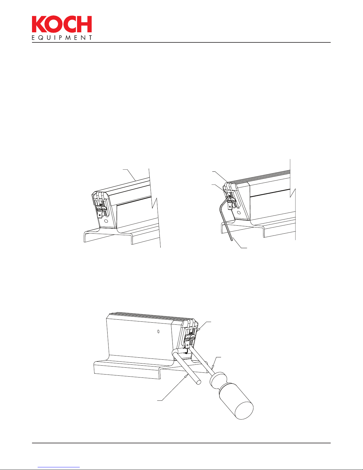
Seal Bar Maintenance
The following illustrations show replacement of the seal elements for the seal bars.
Step 1.
Remove the seal bars from the machine. Pull
off the Teflon
off any remaining Teflon
®
tape strip and discard. Clean
®
tape adhesive
using acetone or an equivalent solvent.
Teflon® tape
TEFLON TAPE
Figure 4.1
Step 2.
Using a 2mm Allen wrench, loosen the set
screws for the cut-off wire and the seal
element on both ends of the seal bar and
discard.
Seal element
SEAL ELEMENT
Set screw
SET SCREW
2mm ALLEN
Figure 4.2
2mm Allen
WRENCH
wrench
Step 3.
If you are replacing the L-shaped spring retainer and the spring at this time, loosen the set
screw and remove the old spring retainer and spring and install the new ones. Adjust the
spring retainer to allow a 1/8-in. gap between the spring retainer and the seal bar. This will
allow the seal element to remain under tension after tightening the seal element.
TIGHTENING TOOL
Figure 4.3
860108•Q
MAINTENANCE •
BRASS CONTACT
SLOTTED TIP
SCREWDRIVER
P A G E 4.2
MAIN: 816-753-2150
TOLL FREE: 800-777-5624
INTERNET: kochequipment.com
E-MAIL: info@kochequipment.com
Reading the Indicators
If your machine is controlled by a digital control module (with touch pad), this design to aids
in troubleshooting. The digital panel has indicator lights mounted on the front below the
ON/OFF switch. The indicator lights correspond to the operating devices and should turn on
and off in the following sequence when the machine lid is closed:
1. Vacuum Pump [C-1]
2. Gas Flush Valve [SOL-3] (optional)
3. Seal Bladder Valve [SOL-2]
(stays on until completion of cycle)
4. Seal Impulse Contactor [C-2]
5. Ventilation Valve [SOL-1]
The device should be operating when the light is illuminated. If the lights illuminate in the
proper sequence, but there is still a problem, look for the problem in the operating device
itself. If the lights do not sequence properly, look for a problem in the control module.
860108•Q
MAINTENANCE •
P A G E 4.3

E-MAIL: info@kochequipment.com
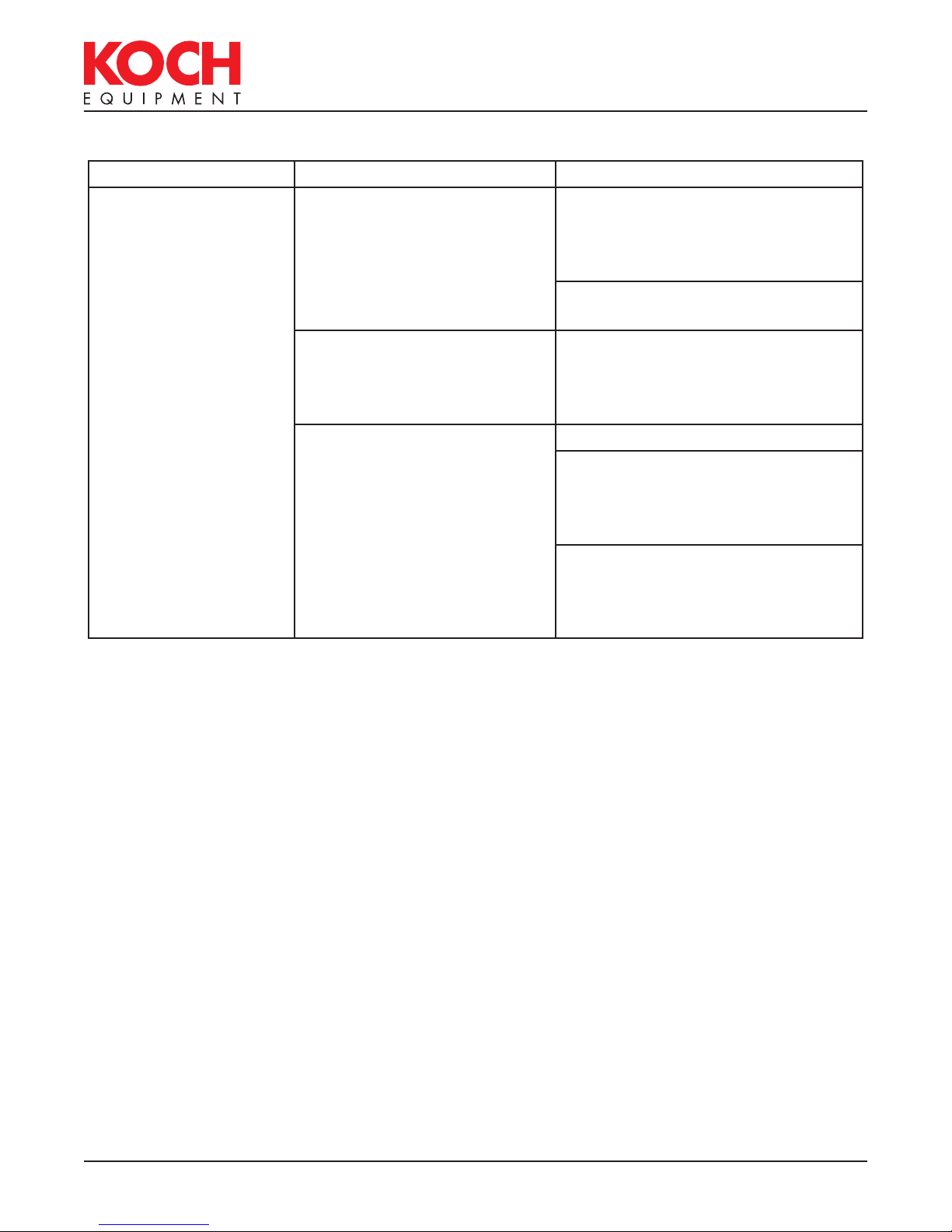
Troubleshooting
Problem Indications Remedy
MAIN: 816-753-2150
TOLL FREE: 800-777-5624
INTERNET: kochequipment.com
Machine will not start Green power “ON” light not
lit when switch is turned on
Make sure that the power
requirements match those given
on the nameplate. Also, check
fuse F-2; replace if blown.
Vacuum pump does not run Make sure that the power
requirements match those given
on the nameplate
No vacuum When lid is closed, indicator
light (VAC) is “OFF” on the
Check lid switches LS-1 for proper
adjustment
control module
Vacuum not pulling lid down Check intake screen in vacuum
pump hose barb for blockage,
pieces of bags, labels, bone, etc.
Longer vacuum cycle times Check intake screen in vacuum
pump hose barb for blockage
No gas flush (optional) If indicator light (GAS) is lit Check for proper gas pressure
going into gas inlet
Check for proper operation of gas
flush valve (SOL-3)
If indicator light (GAS) is not
lit
Chamber not venting
(lid will not open)
Lid will not open and red
indicator light “VENT” on
control module is lit
“VENT” indicator light is not
lit
NOTE: Lid can be released by pulling the hose off of
the vacuum gauge to remove product.
Check gas flush potentiometer on
analog control module or possible
defective digital control panel
Check ventilation valve SOL-1 for
proper operation
Check cool down potentiometer
on analog control module or
possible defective digital control
panel
860108•Q
MAINTENANCE •
P A G E 4.4
E-MAIL: info@kochequipment.com
Troubleshooting
Problem Indications Remedy
MAIN: 816-753-2150
TOLL FREE: 800-777-5624
INTERNET: kochequipment.com
Improper or no
sealing
Seal bladder light on control
module is lit, but the seal bar
does not go up
The seal bar is not heating
up even though the red
seal light on the front panel
comes on
The red seal light on the
front panel either does not
light for the proper length of
time (½ to 1 second) or does
not light at all
Check to make sure that the
regulator knob is turned fully
clockwise or, if air-assist is used,
set to the recommended pressure
Check seal bladder valve SOL-2
for proper operation
Check seal bar connection points
and clips for corrosion and proper
tension
Check for broken seal element
Check seal bar fuse F-1 located on
the analog or digital panel. If the
machine is 110VAC with two seal
bars, F-1 is located on the chassis.
Make sure the seal impulse
potentiometer is set high enough
or check for possible defective
digital control panel
NOTE: For proper sealing, three things must occur:
1. The seal bar must come down and place adequate pressure between the seal bar and
the backup strip.
2. The seal element must heat up sufficiently to fuse the pouch.
3. The pouch must be allowed to cool for a time to ensure a good “set.”
860108•Q
MAINTENANCE •
P A G E 4.5
 Loading...