

Page 1
Operating Manual
for
Flow-Counter/-Dosing Unit/-Controller
Model:
ZOK-ZxP ZOK-ExK/ZxK
ZOK-ExM/ZxM
ZOK-ZxF
Page 2

ZOK-E/-Z
Page 2 ZOK K14/0917
1. Table of Contents
1. Table of Contents ......................................................................................... 2
2. Note .............................................................................................................. 3
2.1 Notice According to the Battery Law ................................................... 3
3. Instrument Inspection ................................................................................... 4
4. Regulation Use ............................................................................................. 4
5. Environment ................................................................................................. 4
6. Instrument / Functions overview ................................................................... 5
7. Electrical connections ................................................................................... 6
7.1 Cable entry for housing option -K ........................................................ 6
7.2 Overview of Terminals ZOK-E/Z with Supply option 3 and 6 ............... 7
7.3 Overview of Connections ZOK-Z with Supply option 0 and 6 .............. 7
7.4 Power Supply ...................................................................................... 8
7.5 Sensor Inputs .................................................................................... 12
7.6 Control Inputs .................................................................................... 21
7.7 Analogue Output (only ZOK-Z3 with Supply option ‘3/6/0’) ............... 23
7.8 Switching output (only ZOK-Z2/-Z3) .................................................. 26
7.9 Pulse Output and Status Output ........................................................ 27
8. Operating and Menu Structure ................................................................... 28
8.1 Overall ............................................................................................... 28
8.2 Measuring Mode ................................................................................ 29
8.3 Menu Mode ....................................................................................... 33
9. General Functions ...................................................................................... 34
9.1 MIN- MAX. Memory (not for ZOK-Z2) ................................................ 34
10.Instrument Parameters ............................................................................... 34
10.1 End of instrument parameterization ................................................... 34
10.2 Overview of menu functions/ instrument parameters ........................ 35
10.3 Signal input ....................................................................................... 39
10.4 Rate Measurement ............................................................................ 43
10.5 Counter ............................................................................................. 44
10.6 Pulse output (only Option ZOK–E3/-Z3) ............................................ 44
10.7 Switching outputs (only for options ZOK-Z2/-Z3) .............................. 47
10.8 Dosing function (only ZOK-Z2) .......................................................... 50
10.9 Analogue output (only option ZOK-E3/-Z3) ....................................... 52
10.10Service .............................................................................................. 53
11.Technical Details ........................................................................................ 55
12.Ordering Details .......................................................................................... 58
13.Dimensions ................................................................................................. 59
14.EU Declaration of Conformance ................................................................. 60
Manufactured and sold by:
Kobold Messring GmbH
Nordring 22-24
D-65719 Hofheim
Tel.: +49(0)6192-2990
Fax: +49(0)6192-23398
E-Mail: info.de@kobold.com
Internet: www.kobold.com
Page 3

ZOK-E/-Z
ZOK K14/0917 Page 3
2. Note
Please read these operating instructions before unpacking and putting the unit into
operation. Follow the instructions precisely as described herein.
The devices are only to be used, maintained and serviced by persons familiar with
these operating instructions and in accordance with local regulations applying to
Health & Safety and prevention of accidents.
When used in machines, the measuring unit should be used only when the machines
fulfil the EC-machine guidelines.
2.1 Notice According to the Battery Law
Old batteries do not belong in household waste. You can send the batteries back to us
or an authorized address, free of charge. As consumer, you are legally obliged to
return the used batteries.
Contaminated batteries are provided with a mark consisting of a crossed-out trash and
the chemical symbol (Cd, Hg, Li or Pb) of heavy metal for classification as respective
contaminant:
Cd1 Hg2 Pb3 Li4
1. "Cd" stands for cadmium.
2. "Hg" stands for mercury.
3. "Pb" stands for lead.
4. "Li" stands for lithium.
Page 4

ZOK-E/-Z
Page 4 ZOK K14/0917
3. Instrument Inspection
Instruments are inspected before shipping and sent out in perfect condition.
Should damage to a device be visible, we recommend a thorough inspection of the
delivery packaging. In case of damage, please inform your parcel service / delivery
agent immediately, since they are responsible for damages during transit.
Scope of delivery:
The standard delivery includes:
Flow counter/-dosing unit/-controller in plastic- universal housing with wall or pipe
mounting set Model: ZOK-Z with universal housing ‘K’
OR
Flow counter/-dosing unit/-controller in panel mounting housing 96x96mm with 2
mounting clips Model: ZOK-Z with panel mount housing ‘P’
Flow counter/-dosing unit/-controller in aluminum field housing, plastic cover PA6
with M16x1.5 cable gland
Model: ZOK-Z with field case 'F'
OR
Oval gear flow meter DON- with electronics option -Z in compact version
Model: ZOK-Z with universal housing ‘M’
Operating Manual
Battery 3.6 V Lithium size AA for data saving function (not for ZOK-Z with ‘P’)
4. Regulation Use
The electronic units ZOK-xx are specifically designed for the calculation, display and
transfer of calculations and flow rates of flow meters with pulse or frequency outputs.
The instruments display flow rate, day counter (resettable) and total counter in the
operator-selected units. A clear multilingual menu guides you through the
programming of the device that largely eliminates the requirement of constant usage of
operating manual. All user-specific program settings are retained even when changing
the battery.
A trouble-free operation of the device is only guaranteed if all instructions in this
manual are complied. We do not accept any liability for damage caused by failure to
follow these instructions.
5. Environment
The electronics options ZOK-ZxK are weather resistant and adequately reflect IP66/67
(NEMA 4X). The electronics are housed in a UV-resistant, glass-filled nylon housing
with stainless steel screws and FPM seals. The options ZOK-ZxP are in a panel mount
housing 96x96 mm with protection class IP44. The option ZOK-ZxF is available in
powder coated aluminum extruded housing with Plastic lids and appropriate protection
class IP 66/67.
The instruments are suitable for harsh indoor or outdoor environments and comply
with EU Directive 2014/30/EU (Electromagnetic Compatibility).
Page 5
ZOK-E/-Z
ZOK K14/0917 Page 5
6. Instrument / Functions overview
Function Z1P/Z1F Z1KZ2P/Z2F Z2
K
Z3P/Z3F Z3KE1K E3K
Dual Counter
x x
x x x x
Dosing function
x x
Controller function
x x
x
Certification
ATEX Certification
x x
Power supply
DC-Supply
x x x x x x x x
AC-Supply
x
x
x
Battery
operation
x
x x x
Sensor supply (only with external power supply)
Sensor supply
8 V/
24 V
8 V
8 V/
24 V
8 V
8 V/
24 V
8 V 8 V 8 V
Electrical outputs (only with external supply)
Relay outputs
xxx
Status outputs
x x x x x x
Analogue
outputs
3 L
2 L/
3 L
2 L/
3 L
Pulse outputs
x x
LCD display
Selectable units
x x x x x x x x
Decimal point
x x x x x x x x
Accumulative total
x x x xx xx x
Resettable total
x x x x x x x x
Linearisation
x x x x x x
Rate display
x x x x x x x x
Backlighting
x x x x x x x x
Arithmetic functions
x x x x x x
Page 6

ZOK-E/-Z
Page 6 ZOK K14/0917
7. Electrical connections
7.1 Cable entry for housing option -K
Up to 3 cable entries (M20x1.5 or ½ "NPT) are available for electric connection in case
of electronics with plastic housing. To use these cable inlets, the existing factory
protection caps must be broken with a tool (e.g. screwdriver) and a suitable cable
gland should be screwed in. The cable glands are not included in the delivery.
Eruption of cable inlets
In case of electronic option ZOK-Z with housing ‘P’, the electrical connection is at the
rear side above the pluggable screw terminals.
Page 7
ZOK-E/-Z
ZOK K14/0917 Page 7
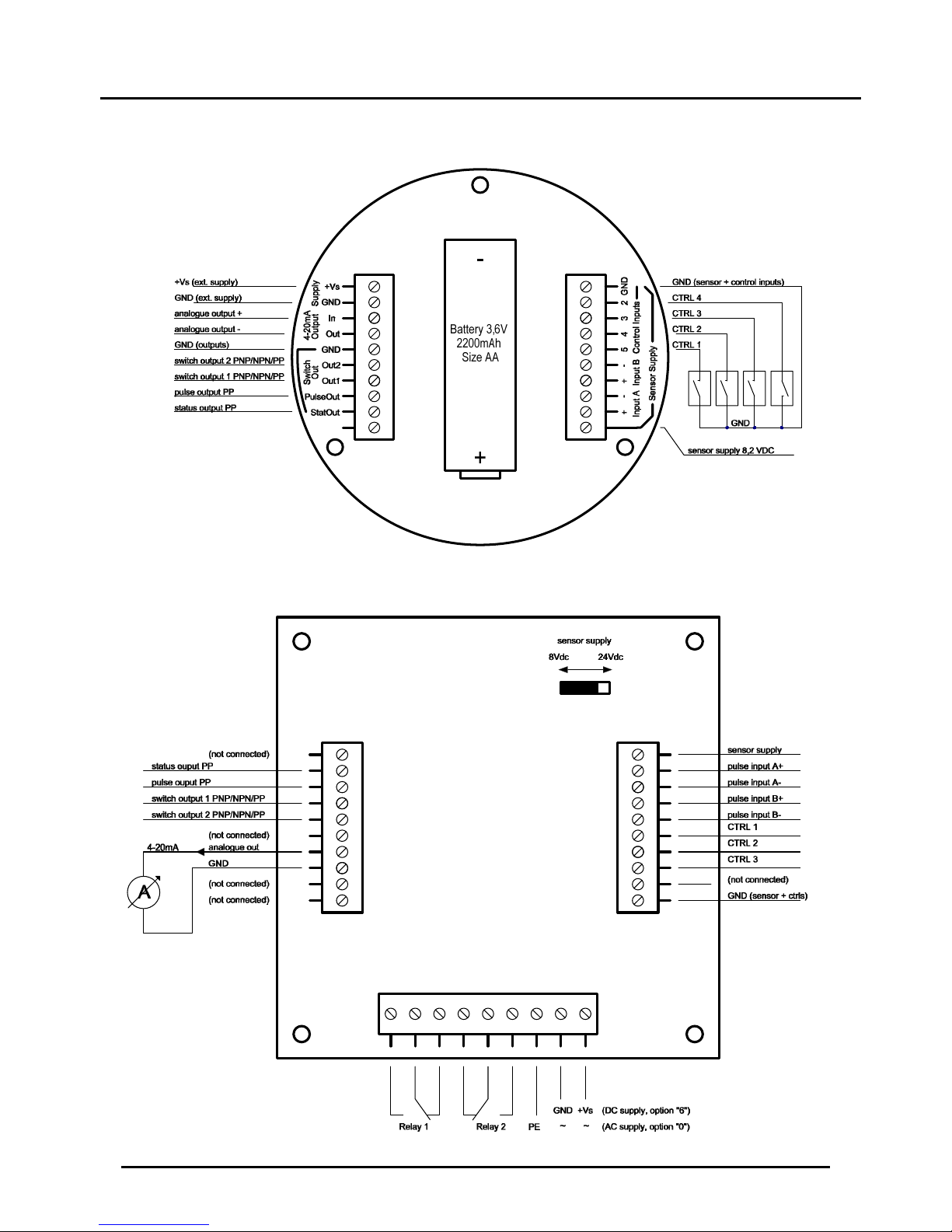
7.2 Overview of Terminals ZOK-E/Z with Supply option 3 and 6
7.3 Overview of Connections ZOK-Z with Supply option 0 and 6
Page 8

ZOK-E/-Z
Page 8 ZOK K14/0917
7.4 Power Supply
Depending on functionality and features, the electronics offer different possibilities for
power supply:
Options ZOK-Z2: External DC-Supply
Options ZOK-Z1: Battery and ext. DC-Supply
Options ZOK-Z3: Battery and ext. DC-Supply and 4-20 mA
Loop current
7.4.1 Storing the counter readings
The storage of meter readings is carried out after each measurement cycle in the
internal FRAM. If the power is interrupted and re-applied, than the meter reading revert
to the last saved values.
7.4.2 External DC-Supply
When electronic units are supplied with external DC voltage, all functions are
available. If no analogue output is used, all instrument functions are ensured on 5 VDC.
When using the analogue output in 3-wire circuit, the supply voltage must be minimum
10 VDC (+ load).
7.4.3 Supply via 4-20 mA Current Loop (only ZOK-Z3 with supply option ‘3’)
The electronic option ZOK-Z3 can alternatively be operated via 4-20 mA current loop
in 2-wire operation. Here we have the following technical limitations:
All other electrical outputs (switching outputs, pulse output and status output) are
disabled
The backlight of the display is switched off and cannot be turned on.
Sensors that do not require an additional power supply can be connected (e.g.
reed switch). Hall sensors require the additional power supply and can therefore
not be used in 2-wire loop operation. In this case, the 3-wire connection must be
used with an external power supply.
To use the 2-wire loop operation, the parameter ‘Wiring type’ in configuration
menu for analogue output must be changed to ‘2-wire’, otherwise the current
output will not be scaled correctly.
For electronics option Z2, no battery can be used due to the relay
board.
If the device is taken out of operation and not used for longer periods,
the battery must be removed. Otherwise, the device is always supplied by
the battery and remains active. As a result, the battery can get discharged.
Page 9

ZOK-E/-Z
ZOK K14/0917 Page 9
7.4.4 Battery operation (only ZOK-Z1/-Z3 with supply option 3)
The options ZOK-Z1/-Z3/-E1/-E3 can also be powered by a battery. In battery mode,
the device function scope is relatively limited:
All electrical outputs (switching outputs, analogue output, pulse output, status
output) are disabled during battery operation.
The backlight of the display is switched off and cannot be turned on.
The sensor may only be used with passive reed switches, as they require no
additional power supply. Usage of induction coils reduces the battery life. Other
sensors, which require a sensor power for operation, are also not suitable for
battery operation.
During battery operation, there are four different types of sleep modes available under
menu point ‘Display’ which can be selected by the user and are numbered from 0-3.
Activation of sleep mode
The duration after which the electronics goes in SLEEP-Mode and SLEEP is
displayed on the display can be adjusted, activated and deactivated with Menu
point ‘Sleep Timeout’. If ‘Sleep Timeout’ is set to ‘0’, SLEEP-Mode is deactivated
and the electronics will always work in Measuring Mode. The ‘Sleep Timeout’ can
be adjusted from 0 to 1800 secs. After the ‘Timeout’ time has passed, the sleep
mode chosen by the user will be activated.
No linearization function is available during sleep modes.
The counter values will be regularly updated in the internal processor.
The flow rate will neither be updated in the processor, nor on the display.
Monitoring of battery voltage during sleep mode
In all sleep modes, after a count of 100 pulses, the battery voltage is monitored. If
this monitoring shows that the voltage has gone below 3.2 V, then the counter
values will be saved.
NOTE: The counter values will be regularly saved in measuring mode and
also in sleep mode if the battery voltage is at a critical level but however it
will not happen during sleep mode with healthy battery.
Battery status indication during sleep mode
With the exception of sleep mode 0, the battery status will be indicated in two
stages during normal measuring mode and all other sleep modes. In sleep mode
with 3.2 battery voltage, ‘Low Bat’ will be displayed on the display and the symbol
‘bat’ on the upper left side of the display will begin to flash. Here we recommend a
battery replacement. Furthermore, in sleep mode when the voltage drops below
3.1 V, ‘CHANGE BAT’ appears on the display. In this case, the battery must be
replaced.
Description of sleep modes
Sleep mode 0 (Default)
Sleep mode 0 is a mode with the lowest current consumption since the display will
be switched off during this mode and only a key press will reactivate it for the
duration of ‚Timeout‘ time. In Menu, the behaviour of the display remains the
same. The menu can be further used by pressing keys anytime.
Page 10

ZOK-E/-Z
Page 10 ZOK K14/0917
Sleep mode 1
In sleep mode 1, the display will be active with an indication ‘SLEEP’ on the
display. In Menu, if the electronics goes to sleep mode, then the last displayed
content will be frozen. The menu can be further used by pressing keys anytime.
Sleep mode 2
In sleep mode 2, the counter values are periodically calculated and displayed on
the display, as long as the pulses are present on either Input A or Input B. In the
absence of pulses, the display will be turned off. The display and the counter
values will be updated after the duration of ‚Refresh rate‘ set by the user. If the
refresh rate is set to e.g. 5 sec, the counter values will be calculated and displayed
on display after these 5 seconds. Longer refresh rate will increase the battery life.
‚BAT LOW‘ will be displayed on the display if battery voltage falls below 3.2V and
‚CHANGE BAT‘ will be shown in case if the voltage falls below 3.1V.
In Menu, if the electronics goes to sleep mode, then the last displayed content will
be frozen. The menu can be further used by pressing keys anytime. In measuring
mode, instead of flow rate, indication ‘SLEEP’ will be shown.
Sleep mode 3
Sleep mode 3 is same as sleep mode 2 with the exception that the display is
always on.
The menu mode will not be automatically exited when no key is pressed for a
certain time. The menu mode remains active until the user presses the RET button
till the normally measuring mode appears. In battery operation, a long stay in
menu mode will shorten battery life.
Page 11

ZOK-E/-Z
ZOK K14/0917 Page 11
The supplied battery type 3.6 V AA Lithium (2200 mAh) should be inserted in the
battery holder on the back side of the electronic (correct polarity is important!).
The following type of battery is required to replace the supplied battery:
3.6 V Lithium, Size AA, minimum capacity 2200 mAh, IEC-Type CR14505
e.g: EVE Type ER14505M, SAFT LS14500, TADIRAN SL360S/SL760
Battery life duration: The achievable battery life is dependent on various factors:
On the frequency of activation of measurement / menu mode (in the measurement
/ menu mode, power consumption is higher)
On the total number of detected input pulses and the input frequency(higher
frequencies reduce the battery life)
On the environmental conditions - low temperatures reduce the usable battery
capacity.
Batterylife
(Months)
SLEEPmode0 SLEEPmode1
MenuMode/
Measuringmode
17‐20 9‐10 1
Inputsignal
(Hz)
Batterylife
(Months)
SLEEPmode2 SLEEPmode3
0 20 8
1 8 8
100 7 7
1000 3 3
Page 12

ZOK-E/-Z
Page 12 ZOK K14/0917
7.5 Sensor Inputs
7.5.1 Active pulse signal
Power Supply: External DC-Supply
Signal input setting: „AKTIVES SIGNAL“
Wiring for ZOK-Z with Supply option 3 and 6:
Wiring for ZOK-Z with Supply option 0 and 6:
Page 13
ZOK-E/-Z
ZOK K14/0917 Page 13
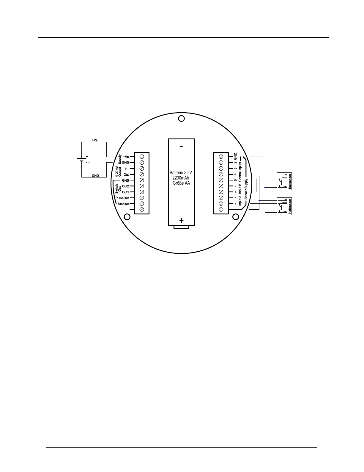
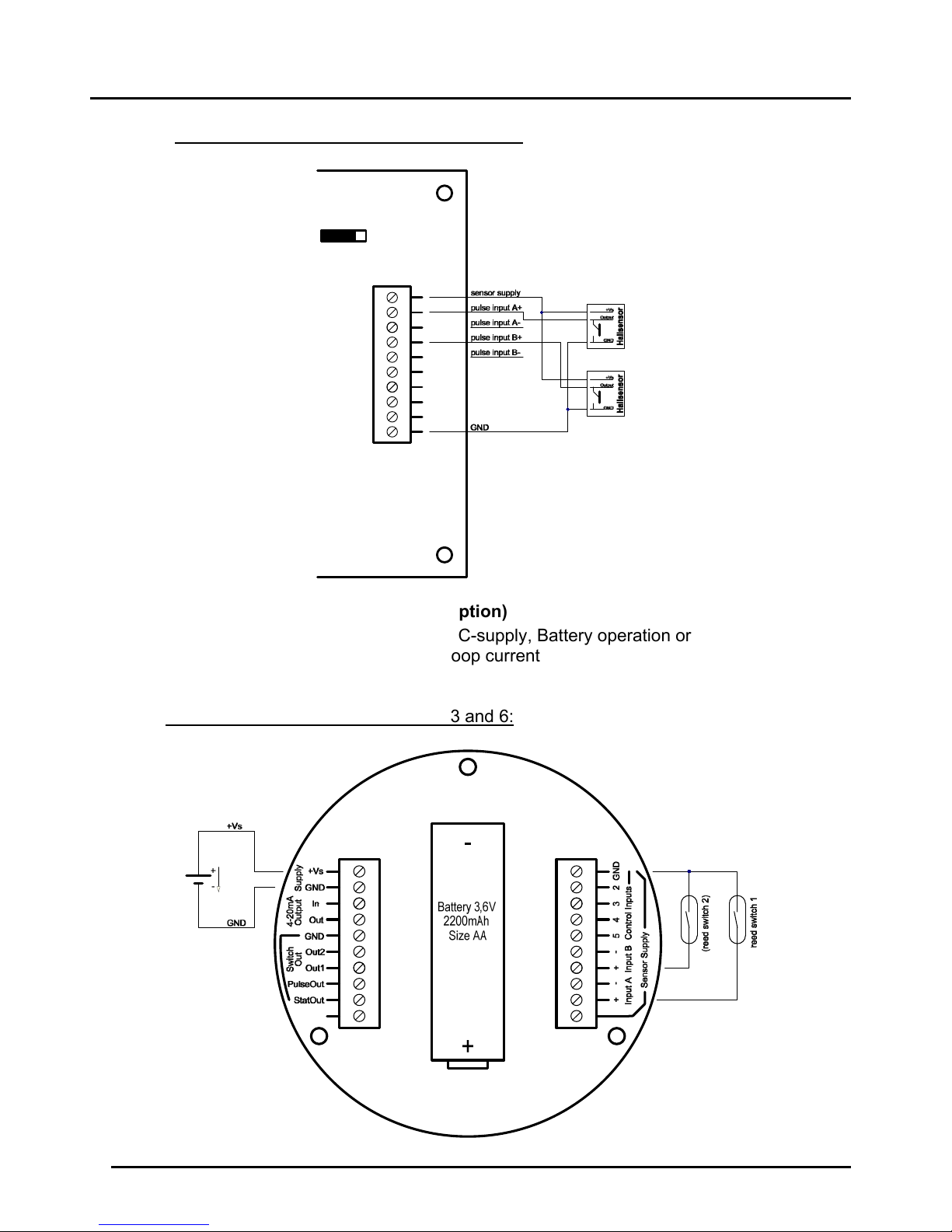
7.5.2 Hall Sensor, NPN- and PNP-Sensors
Power supply: only external DC-supply
Signal input setting: „HALL“
Signal input setting: „NPN“
Signal input setting: „PNP“
Wiring for ZOK-Z Supply option 3 and 6:
Page 14
ZOK-E/-Z
Page 14 ZOK K14/0917
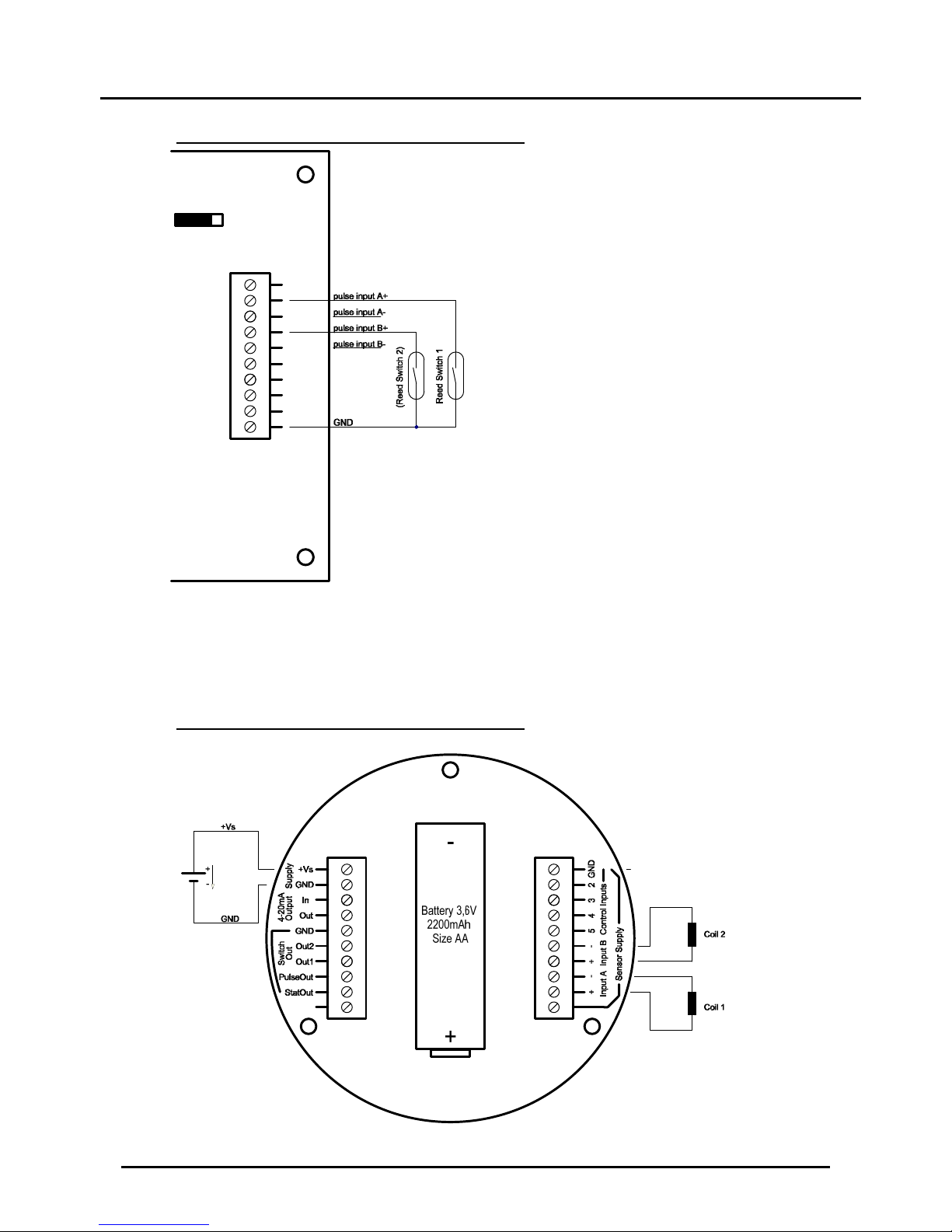
Wiring for ZOK-Z with Supply option 0 and 6:
7.5.3 Reed switch (-R0 Sensor option)
Power supply : External DC-supply, Battery operation or
4-20 mA loop current
Signal input setting: „REED “
Wiring for ZOK-Z with Supply option 3 and 6:
Page 15
ZOK-E/-Z
ZOK K14/0917 Page 15
Wiring for ZOK-Z with Supply option 0 and 6:
7.5.4 Inductor
Power supply: External DC-supply and battery operation
(Battery operation reduces battery life)
Signal input setting: „Inductor“
Wiring for ZOK-Z with Supply option 3 and 6:
Page 16
ZOK-E/-Z
Page 16 ZOK K14/0917
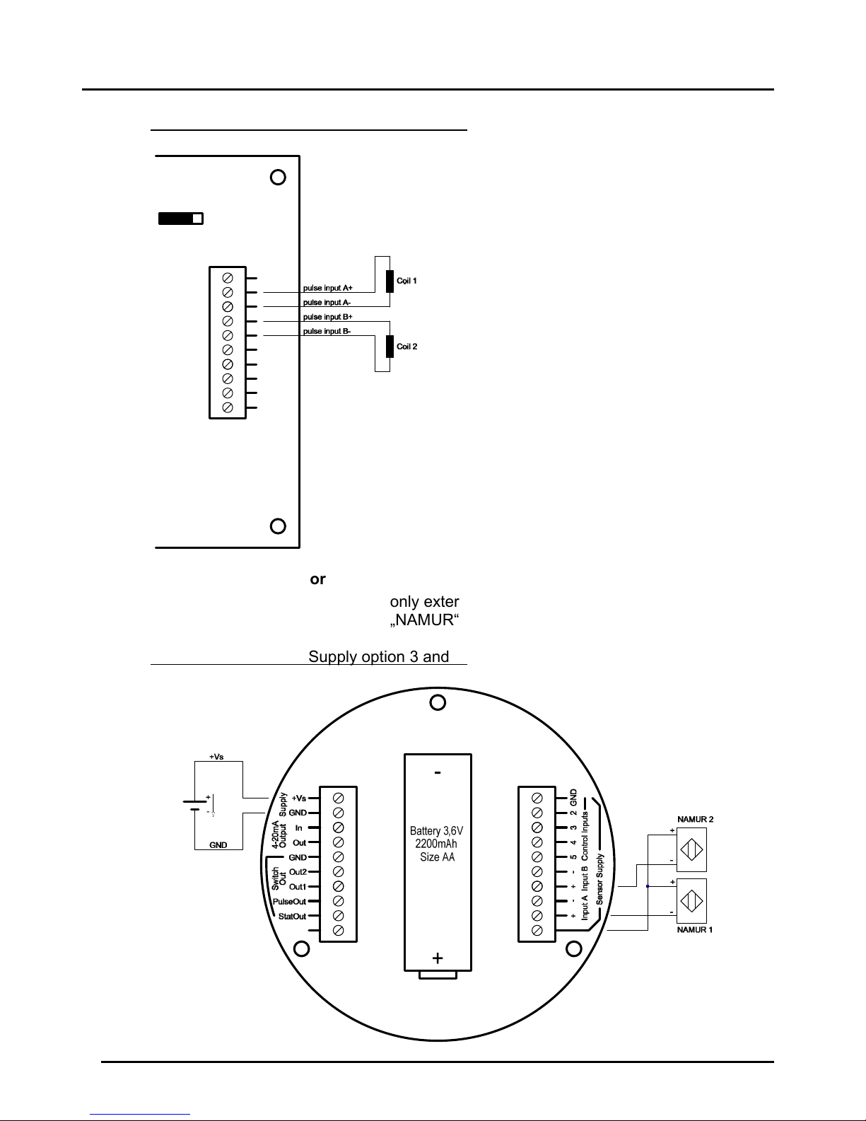
Wiring for ZOK-Z with Supply option 0 and 6:
7.5.5 Namur-Sensor
Power supply: only external DC-supply
Signal input setting: „NAMUR“
Wiring for ZOK-Z with Supply option 3 and 6:
Page 17
ZOK-E/-Z
ZOK K14/0917 Page 17
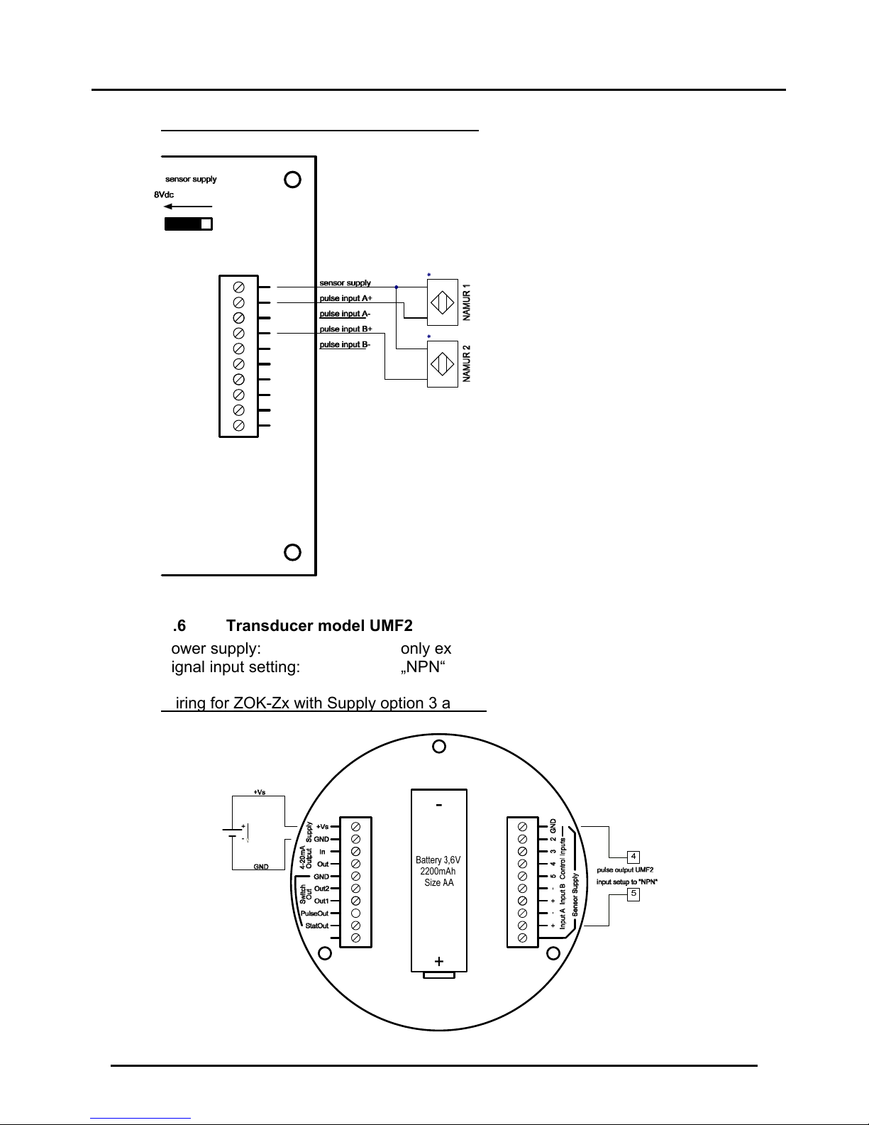
Wiring for ZOK-Z with Supply option 0 and 6:
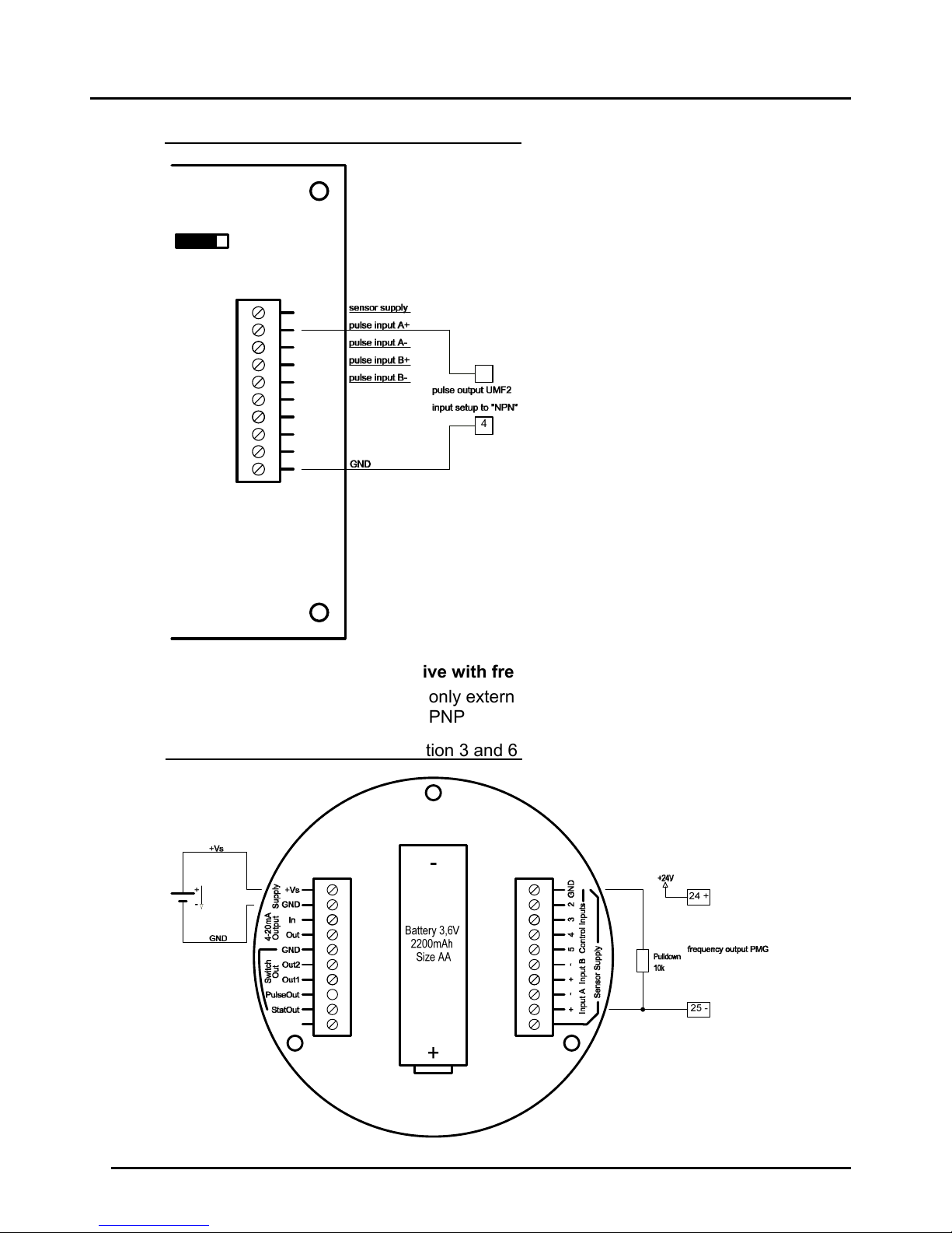
7.5.6 Transducer model UMF2
Power supply: only external DC-supply
Signal input setting: „NPN“
Wiring for ZOK-Zx with Supply option 3 and 6:
Page 18
ZOK-E/-Z
Page 18 ZOK K14/0917
Wiring for ZOK-Zx with Supply option 0 and 6:
7.5.7 PMG (magnetic inductive with frequency output)
Supply Voltage: only external DC power supply
Signal input setting: PNP
Wiring for ZOK-Zx with Supply option 3 and 6:
5
4
Page 19

ZOK-E/-Z
ZOK K14/0917 Page 19
Wiring for ZOK-Zx with Supply option 0 and 6:
Page 20

ZOK-E/-Z
Page 20 ZOK K14/0917
7.5.8 DOR
with voltage pulse output
DOR-with Hall sensor output
Page 21

ZOK-E/-Z
ZOK K14/0917 Page 21
7.6 Control Inputs
There are 3 control inputs for external controlling of instrument functions. The
activation of each function can be done through:
a.) an active control input or
b.) Carried out by a passive N/O contact.
In both cases, the function will be activated on switching from HIGH to LOW level
(falling edge).
When using an active control signal, the signal amplitude of the HIGH level must be
from 5 to 24Vdc. When using simple normally open contact, the input potential is
internally pulled of HIGH, if the contact is open. If the contact is closed, the input
potential is pulled to GND and the control function is activated.
CTRL4 control input is not used.
Function of control inputs:
Control input
ZOK-E1/-Z1
ZOK-E3/-Z3
ZOK-Z2
CTRL1 Reset MIN / MAX memory Dosing Start / Stop
CTRL2 Reset partial input A Dosing value reset
CTRL3 Reset partial input B CTRL4 - -
Page 22

ZOK-E/-Z
Page 22 ZOK K14/0917
Wiring for ZOK-Z with Supply option 3 and 6:
Wiring for ZOK-Z with Supply option 0 and 6:
Page 23

ZOK-E/-Z
ZOK K14/0917 Page 23
7.7 Analogue Output (only ZOK-Z3 with Supply option ‘3/6/0’)
7.7.1 2-Wire Configuration 4-20 mA
The options ZOK-Z3/-E3 can be operated as a source in a 2-wire 4-20 mA current
loop. However, only passive Reed switch (option -R0) should be used as a sensor. In
2-wire loop operation, no other active outputs are available. If the electronics is
connected in 2-wire configuration, the display will show „LOOP“ at the top. The wiring
type must be set to "2-WIRE" in the Analogue Output menu.
7.7.2 3-Wire Configuration as active output, current source
In the 3-Wire Configuration, the load is connected between current output (-) and GND
and all types of sensors can be connected and all other outputs can be used. If the
electronics is connected in 3-wires, the display will show „EXT“ at top left (external
power supply). The wiring type must be set to "3-WIRE" in the Analogue Output menu.
All sensor types can be connected at the signal input.
Page 24

ZOK-E/-Z
Page 24 ZOK K14/0917
Wiring for ZOK-Z3 with Supply option ‚3/6‘:
Wiring for ZOK-Z3 with Supply option ‘0/6’:
Page 25

ZOK-E/-Z
ZOK K14/0917 Page 25
7.7.3 3-Wire Configuration as passive output, current sink
(only ZOK-Z3 with Supply option ‘3/6’)
In the wiring 3-wire passive current sink, the load (load) is connected between current
output (+) and voltage source (+Vs). In the 3-conductor wiring, all types of sensors can
be connected and all other outputs can be used. If the electronic is connected in 3conductor wiring, the display will show „EXT“ at top left (external power supply). The
wiring type must be set to "3-WIRE" in the Analogue Output menu. All sensor types
can be connected at the signal input.
Page 26

ZOK-E/-Z
Page 26 ZOK K14/0917
7.8 Switching output (only ZOK-Z2/-Z3)
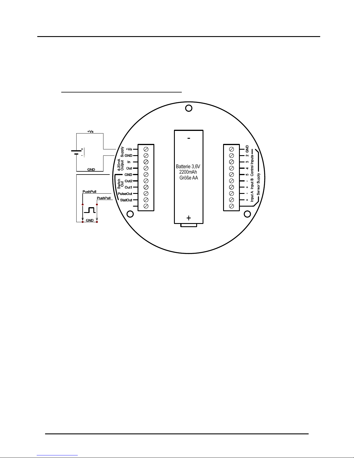
7.8.1 Transistor Output
The transistor outputs can be configured by software as PNP, NPN or push-pull
output. In case of push-pull configuration, output will be switched between active-HIGH
or LOW potential. The load can either be connected to GND or + Vs. In push-pull
mode, no additional pull-up or pull-down resistor is required.
7.8.2 Relay outputs (for ZOK-Z2/-Z3)
The electronics options ZOK-Z2/-Z3 devices are equipped with potential-free relay
outputs as standard. Electronic option ZOK-Z2 is equipped with an additional relay
board. These relay outputs can be simultaneously used in parallel with the existing
transistor outputs. The outputs of the relay 1 are controlled by the switching output
SW1 and of relay 2 by SW2.
output
Page 27
ZOK-E/-Z
ZOK K14/0917 Page 27
7.9 Pulse Output and Status Output
Pulse and status outputs are set to push-pull output type and provide an active digital
signal with HIGH amplitude of about + Vs.
Wiring for ZOK-Z3 with Supply option 3/6:
Page 28

ZOK-E/-Z
Page 28 ZOK K14/0917
8. Operating and Menu Structure
8.1 Overall
8.1.1 Functions of operating buttons
Button Symbol
Function
Measuring mode Menu mode
Menu / Return
Enter Menu mode
To be pressed
for 3-5 sec
During the parameter setting,
back to main menu / return to
the measurement mode/jump
to the previous decimal
position while setting
numerical values
Down Call MIN-Function
Menu item selection /
incrementing and
decrementing digits while
setting numerical values on
the display
Top Call MAX-Function
Enter
Resets the Partial
counters A and B when
pressed for 3-5 sec.
Numerical input: Jump to the
next decimal position
General: Saves the
parameter value and returns
to the parent menu
8.1.2 Parameter setting
8.1.2.1 Selection list
Parameter with predefined selection values are defined by list selection. The currently
selected menu item will be highlighted with dark background. -buttons are
used to move the selection cursor and with -button, the selection can be
confirmed.
Page 29

ZOK-E/-Z
ZOK K14/0917 Page 29
8.1.2.2 Numerical value input
While setting parameters with numerical value, the assigned unit is always displayed
above the input field in square brackets. The maximum size and the number of
decimal places are fixed and cannot be changed. While setting the numerical value of
a parameter, the left outer position is highlighted first. These positions can be assigned
with numbers from 0 to 9 with the help of buttons. By pressing button,
the input cursor moves to right and the next digit can be changed. In case of a false
entry at the previous position, the cursor can be moved again to left by pressing
key and the correction can be made. If the cursor is on the far right, the set value is
saved by pressing the button and the display changes to the parent menu.
8.2 Measuring Mode
After applying the supply voltage, the electronics starts in measurement mode. In this
mode, the input signals are recorded continuously; current instantaneous flow and
volume counter readings are periodically calculated and displayed. With options ZOKZ2, a dosing function is available.
On LCD, in addition to main display, the status and configuration of the pulse inputs,
as well as the status of the pulse output, the switching outputs and supply voltage are
also displayed.
If a symbol is shown inverted (with dark background), it means that the associated
hardware is active and its signal is connected to the electronics.
8.2.1 Display range of the Volume Counter
The number of digits that appear on the display for volume counter (partial and total
volume counter) is at limited to maximum 8 digits (without decimal point) and 7digits
(with decimal point). If the 7- or 8-digit display range is exceeded, the display will
signal/represent it by displaying 8 hash signs (########). In this case, the counter
cannot be read. The user has then the possibility of changing the Unit of the volume
counter or of changing the number of decimal points in the Volume Menu so that the
counter values can be brought back again within the display range.
Page 30

ZOK-E/-Z
Page 30 ZOK K14/0917
8.2.2 Display layout in measuring mode single channel (ZOK-Z1/E1/Z3/E3)
part- or total volume
display
input A
part- or total volume
display
input A
Unit associated to main display
Page 31

ZOK-E/-Z
ZOK K14/0917 Page 31
8.2.3 Display layout in measuring mode for dual channel (ZOK-Z1/E1/Z3/E3)
Page 32

ZOK-E/-Z
Page 32 ZOK K14/0917
8.2.4 Display layout in measuring mode for dossier ZOK-Z2
Page 33

ZOK-E/-Z
ZOK K14/0917 Page 33
8.3 Menu Mode
In the menu, all device parameters can be set. The individual parameters are
organized into groups according to their function. While the menu mode is turned on,
the input signal detection and pulse output (option -Z3) are still active in the
background. After leaving the menu mode, all display parameters are then updated
again in measurement mode.
Note: The menu mode is not exited automatically even after a certain time without key
operation. The menu mode remains active (in battery mode) until the user has once
pressed the button.
In battery mode, a long stay in menu mode shortens battery life.
To activate the Menu mode, the button must be pressed for 3-5 sec. The
parameters are divided into main groups and subgroups. Selected menu parameters
are highlighted with dark background. For selection of main groups, and
buttons are used. In the main menu, all menu groups can not be displayed
simultaneously on the screen so the list of menu items can then be scrolled up or
down. To choose the selected item, button should be pressed and the device
goes into relevant sub-menu i.e. into the parameter setting level. For selection of
predefined parameter values, and buttons are used. After changing
the value of the parameter, button should be pressed to save it and to return to
the previous menu level. The return to the main menu or exit to the menu mode takes
place by repeatedly pressing .
Page 34

ZOK-E/-Z
Page 34 ZOK K14/0917
9. General Functions
9.1 MIN- MAX. Memory (not for ZOK-Z2)
The MIN-MAX memory function stores the absolute maximum and minimum measured
value of the flow rate since the last reset or since the last device start. The current
memory values can be displayed and if required reset by pressing or in
measurement mode.
The reset function resets the memory values to the current reading.
Status output
The status output plays the role of an alarm output and is only activated in the
following situations:
Electronic type Function Event
Dosing unit
ZOK-Z2
During dosing No input pulse during the time "Missing pulse
timeout“
Controller
ZOK-E3/-Z3
Mode "Dual
Direction Detection"
Signal at one of the input i.e. A or B is not
recognized or is not available
Controller
ZOK-E3 / -Z3
Mode "dual
independent" /
"Channel A single"
Measuring range endpoint exceeded for input
A or B and overflow occurred
In case of dosing, this output monitors the flow of the medium when for example a
valve is opened at the start of the dosing and no medium flows or if the sensor has
malfunctioned even if the flow is there, then this output will be activated giving
indication of some abnormality.
In case of the detection of direction, this output indicates if both the sensors are giving
their respective signals. If one of them stops working, this output will be activated.
10. Instrument Parameters
10.1 End of instrument parameterization
All ZOK-E/-Z electronics options are preconfigured at the factory when ordered with
Oval Gear meter. A change in the parameters of the menu groups "Signal Input" and
"Rate measurement" should not be made.
With subsequent changes of volume or flow rate units, dependent parameters will be
converted and adapted accordingly. The threshold parameters of the switching outputs
must be checked and adjusted by the user manually in case of change of volume or
flow rate units - this will not be converted automatically.
In a basic scaling, all parameters of the menu groups "Input" and "Rate Measurement"
must be edited successively.
An accidental change of configuration can be restored through “Factory defaults’’
function in Service User Service Factory defaults.
Page 35

ZOK-E/-Z
ZOK K14/0917 Page 35
10.2 Overview of menu functions/ instrument parameters
Menu level Sublevel
Parameter
level
Description Value range
Default
value
available
with
Electronics
type
available with
voltage type
Language
German
English
Spanish
French
English Z1,Z2,Z3
Battery,external
Display
Contrast Display contrast
0 -50 45 Z1,Z2,Z3
Battery,external
Backlight Display
0 - 100 100 Z1,Z2,Z3
external
Time out
Time out of
backlight
OFF, 5s, 10s,
20s, 30s
OFF Z1,Z2,Z3
external
Layout 6 Display layouts
Part/Total
[default] Z1,Z3
Battery,external
Total/Part
Rate/Part
Part/Rate
Rate/Total
Total/Rate
Sleep Timeout
saves the battery
life when not set
to '0'
0-1800 sec
30 sec Z1,Z3
Battery
Sleep mode 4 sleep modes
Sleep mode 0
Sleep
mode 0
Z1,Z3
Battery
Sleep mode 1
Sleep mode 2
Sleep mode 3
Signal Input
Sensor type A
NPN
For NPN sensors
List selection [default]
Z1,Z2,Z3
Battery,external
Spule
For induction coils
Z1,Z2,Z3
Battery,external
PNP
For PNP sensors
Z1,Z2,Z3
Battery,external
Active Signal
For active pulse
signals
Z1,Z2,Z3
Battery,external
NAMUR
NAMUR Sensor
Z1,Z2,Z3
Battery,external
Reed
For Reed sensors
Z1,Z2,Z3
Battery,external
Hall
For Hall sensors
Z1,Z2,Z3
Battery,external
Sensor type B
NPN
For NPN sensors
List selection [default]
Z1,Z3
Battery,external
Spule
For induction coils
Z1,Z3
Battery,external
PNP
For PNP sensors
Z1,Z3
Battery,external
Active Signal
For active pulse
signals
Z1,Z3
Battery,external
NAMUR
NAMUR Sensor
Z1,Z3
Battery,external
Reed
For Reed sensors
Z1,Z3
Battery,external
Hall
For Hall sensors
Z1,Z3
Battery,external
Input type
Input A single One channel
service
List selection [default]
Z1,Z2,Z3
Battery,external
Dual direction
det..
Two-channel
operation with
direction
recognition
Z1,Z3
Battery,external
Dual
independent
Two-channel
independent
operation
Z1,Z3
Battery,external
A+B Two-channel
addition operation
Z1,Z3
Battery,external
Page 36

ZOK-E/-Z
Page 36 ZOK K14/0917
Menu level Sublevel
Parameter
level
Description Value range
Default
value
available
with
Electronics
type
available with
voltage type
A-B Two-channel
subtraction
operation
Z1,Z3
Battery,external
Input Signal Timeout
Waiting time
1 – 20 s (Step
size 0,5s)
[1 s] Z1,Z2,Z3
Battery,external
Filter
Filter factor
Filter Size
1-50 1 Z1,Z2,Z3
Battery,external
Jump det.
threshold
Jump threshold
for jump-detector
function
0,05 – 1,00 0,1 [xFS] Z1,Z2,Z3
Battery,external
Jump det.
factor
Factor for jump
detector
confirmation
1-25 1 Z1,Z2,Z3
Battery,external
Hardware filter
active / inactive Z1,Z2,Z3
Battery,external
Scaling A
Linearization Linearization
activation
active / inactive inactive Z1,Z2,Z3
Battery,external
Linearization
points
Number of
linearization
points
0 - 9 0 Z1,Z2,Z3
Battery,external
Menu item "linearization points" dependent on the activation of the
linearization function
Battery,external
Volume unit Volume unit for
scaling factor A
ml, L, m
3
,
galUS, galUK,
barrel, User
L Z1,Z3
Battery,external
Scaling-factor
A0 / Flowrate
A0
Flow rate for
scaling point A0
[LPM] 000010.00 Z1,Z3
Battery,external
Scaling-factor
A0 / K-Factor
A0
K-Factor for
Scaling factor A0
[LPM] 000020.00
Battery,external
Scaling-factor
Ax / Flowrate
Ax
Flow rate for
scaling point Ax
[1 / Volume
unit]
000050.00 Z1,Z3
Battery,external
Parameter points Ax depend on the activation of the linearization
function and the number of linearization points.
Battery,external
Scaling B
Volume unit Volume unit for
scaling factor B
ml, L, m
3
,
galUS, galUK,
barrel, User
L Z1,Z3
Battery,external
Scaling-factor
B0 / Flowrate
B0
Flow rate for
scaling point B0
[LPM] 000010.00 Z1,Z3
Battery,external
Rate
measurement
Refreshrate
Measurement
repetition rate
0,5 – 10 [s]
0,5 Z1,Z2,Z3
Battery,external
Unit
Unit for flow rate
measreument
ml/m, L/m, L/h,
m
3
/h, galUS/m,
galUS/h,
galUK/m,
galUK/h, User
L/m Z1,Z2,Z3
Battery,external
Start point A
MA-value input A
[User]
00000.000 Z1,Z2,Z3
Battery,external
End point A
ME-value input A
[User]
00100.000 Z1,Z2,Z3
Battery,external
Start point B
MA-value input B
[User]
00000.000 Z1,Z3
Battery,external
End point B
ME-value input B
[User]
00100.000 Z1,Z3
Battery,external
Overflow value
Allowable range
can exceed to
overflow value
0 -100 [%FS]
10 Z1,Z2,Z3
Battery,external
Memory reset
Reset of MINMAX memory
Yes/ No
No Z1,Z2,Z3
Battery,external
Counter Volume unit
Overall volume
units for counter
mL, L, m
3
,
galUS, galUK,
barrel, User
L Z1,Z2,Z3
Battery,external
Page 37

ZOK-E/-Z
ZOK K14/0917 Page 37
Menu level Sublevel
Parameter
level
Description Value range
Default
value
available
with
Electronics
type
available with
voltage type
Decimal count
sets the decimal
points
0-4
Z1,Z3
Battery,external
Partvolume A reset
Reset subset
counter A
Button
selection Yes /
No
-
Z1,Z2,Z3
Battery,external
Partvolume B reset
Reset subset
counter B
Z1,Z3
Battery,external
Puls-output
Pulsoutput enable - Enabled/
disabled
disabled
Z3
external(3‐wire)
Source List selection Selection of the
associated signal
input
According to
the ‚Input type‘
in Menu ‚Signal
Input‘
Input A
Z3
external(3‐wire)
Pulse volume Input volume per
output pulse in [L]
4.3 [Volume
unit]
1.000
Z3
external(3‐wire)
Volume unit Volume unit input
for pulse output
mL, L, m3,
galUS, galUK,
barrel, User
L
Z3
external(3‐wire)
Pulse width Sets the pulse
width of pulses
1ms-20s
2ms
Z3 external(3-wire)
Switching
outputs
Output 1
Function
Disabled / Limit
function /
Window
function
Deaktiviert Z3
external(3‐wire)
Source Assigning
switching output
According to
the ‚Input type‘
in Menu ‚Signal
Input‘
Eingang A Z3
external(3‐wire)
Output type Assignment
output stage type
NPN / PNP /
PP
NPN Z3
external(3‐wire)
Switching
function
Acting direction
switching function
Normally open /
Normally
closed
N.o. Z3
external(3‐wire)
Switching
threshold
Switching
threshold
5.1 [Unit]
00035.0 Z3
external(3‐wire)
Lower
threshold
Threshold point
low
5.1 [Unit]
00010.0 Z3
external(3‐wire)
Hysteresis Switching
hysteresis
5.1 [Unit]
00001.0 Z3
external(3‐wire)
Suppresion
factor
Switching delay
factor
0 – 60
[x Refresh]
0 Z3
external(3‐wire)
Output 2
Function
Disabled / Limit
function /
Window
function
Deaktiviert Z3
external(3‐wire)
Source Assigning
switching output
According to
the ‚Input type‘
in Menu ‚Signal
Input‘
Eingang A Z3
external(3‐wire)
Output type Assignment
output stage type
NPN / PNP /
PP
NPN Z3
external(3‐wire)
Switching
function
Acting direction
switching function
Normally open /
Normally
closed
N.o. Z3
external(3‐wire)
Switching
threshold
Switching
threshold
[Unit]
00035.0 Z3
external(3‐wire)
Lower
threshold
Threshold point
low
[Unit]
00010.0 Z3
external(3‐wire)
Hysteresis Switching
hysteresis
[Unit]
00001.0 Z3
external(3‐wire)
Suppresion
factor
Switching delay
factor
0 – 60
[x Refresh]
0 Z3
external(3‐wire)
Analogue
output
Flowrate for 20 mA - [Unit]
00100.000 Z3
external
Wiring type
Establishing
external circuit
2-wire / 3-wire
3-wire
Z3
external
Page 38

ZOK-E/-Z
Page 38 ZOK K14/0917
Menu level Sublevel
Parameter
level
Description Value range
Default
value
available
with
Electronics
type
available with
voltage type
type
0' Offset
Setting '0' flow to
a particular
current
4-20 mA
4 mA Z3
external
Service
User service
Change
passwort
Changing user
password
5-digit number
(00000 =>
open access)
0 Z1,Z2,Z3
Battery,external
Factory
defaults
Reset the device
to factory settings
No / Yes
No Z1,Z2,Z3
Battery,external
Menu item
selection
Hiding function for
menu items
All menu items
from menu
level selectable
No Menu
item
Z1,Z2,Z3
Battery,external
Factory
service
Password protected - reserved for factory settings
Z1,Z2,Z3
Battery,external
Device status
Devicetype Displays devicetype
Z1,Z2,Z3
Battery,external
Counterstat Displays counter reading
Z1,Z2,Z3
Battery,external
Firmwareversion Displays Firmwareversion
Z1,Z2,Z3
Battery,external
Switching
outputs
Output 1
Function
Disabled
/Dosing low
flow
disabled Z2
external
Source
Assigning
switching output
Input A
Input A Z2
external
Output type
Assignment
output stage type
NPN / PNP /
PP
NPN Z2
external
Switching
function
Acting direction
switching function
Normally open /
Normally
closed
N.o. Z2
external
Output 2
Function
Disabled
/Dosing high
flow
disabled Z2
external
Source
Assigning
switching output
Input A
Input A Z2
external
Output type
Assignment
output stage type
NPN / PNP /
PP
NPN Z2
external
Switching
function
Acting direction
switching function
Normally open /
Normally
closed
N.o. Z2
external
Dosing
function
Function
Stage 1 / Stage 2 Stage 1 / Stage
2
Stage 1 Z2
external
Dosing value
Defining dosage
amount
[Dosing Unit]
01000.0 Z2
external
Dosing unit
Unit volume for
dosing value
mL, L, m
3
,
galUS, galUK,
barrel, User
L Z2
external
Count direction
Count direction of
the dosing value
during the dosing
increasing /
decreasing
increasing Z2
external
Start delay high flow (only with
function "stage 2")
Dosage amount
up to turning on
stage. 2
[Dosing Unit]
00010.0 Z2
external
Stop delay high flow (only with
function "stage 2")
Dosage amount
up to turning off
stage. 2
[Dosing Unit]
00010.0 Z2
external
Dosing value max limit
Setting dosing
limit
[Dosing Unit]
02000.0 Z2
external
Dosing correction
Dosing
correcction value
±
[Dosing Unit]
00000.0 Z2
external
Missing PulseTimeout
Alarm timeout
during dosing
[s]
2 Z2
external
Page 39

ZOK-E/-Z
ZOK K14/0917 Page 39
10.3 Signal input
10.3.1 Signal input / Sensor type
Each of the two pulse inputs can be optimally customized to different sensor types in
Menu, so that at the time of connection no further additional wiring is required for
correct function.
Menu Parameter Sensor type Internal wiring
NPN Hall sensor, Reed switch and all NPN
sensors
Pull-Up resistor
Coil For induction coil
(Amplitude > 20 mVpp)
High impedance input
PNP For all PNP-Sensors Pull-Down resistor
Active signal For all sensors with active output signal,
e.g. (push-pull outputs)
NAMUR For sensors with 2-wire interface according
to EN 60947-5-6 (NAMUR)
Pull-Down resistor 1kOhm
Reed Reed switch Pull-Up resistor
Hall For Hall sensors Pull-Up resistor
10.3.2 Signal input / Input type
The 2 pulse inputs can be configured in different modes together or independently.
The following modes are available:
Parameter
Menu
Description
Input A single
Single-channel mode, only input A is active. Signals at the input B
are not evaluated.
Dual direction
det.
Two-channel operation with flow direction detection. At Channel A
and B, two signals are applied, both signals have equal frequency
and differ only in the phase angle. The flow direction is indicated as
positive when the signal at input B lags behind the signal at input B.
Dual
Independent
Both channels are evaluated, recorded and displayed
independently.
A+B
Both channels are recorded independently. The evaluation of the
flow indicator and the flow meter is done at any time as a sum of
the two signals.
A-B
Both channels are recorded independently. The evaluation of the
flow indicator and the flow meter is done at any time as a difference
of the two signals..
Page 40

ZOK-E/-Z
Page 40 ZOK K14/0917
10.3.3 Signal Input / Input Timeout
For the detection of input signals, the period duration of signal is determined within a
measuring cycle i.e. Refresh time. However, if within the "refresh time" the input period
is not complete i.e. if the input signal has a frequency lower than the frequency
determined from the ‘’Refresh time’’, then the flow indicator is set to "0". In the shortest
"refresh time" of 0.5 seconds, only a minimum input frequency of 1/0.5 = 2 Hz is
recorded. In order to detect even lower frequencies, "Input Timeout" parameter can be
configured up to 20 s. After the completion of „Refresh time“, the signal processing
waits for the full input period until the additional waiting period is expired. It should be
noted that by increasing the waiting time, the reaction time for the detection, for
example, a flow failure is greatly increased. The "Input Timeout" should only be large
enough so that the smallest frequency signal from the connected sensors can be
detected.
10.3.4 Signal Input / Filter
In case of discontinuous input signals, the integrated filter function can filter the display
of flow rates, the analogue output and the switching outputs (only options E3/Z3).
Despite filtering effect, the reaction time to rapid changes in the flow rate can be kept
low by appropriate choice of filter parameters.
The time base for the filtering function is the "Refresh time". The filter function
operates on the principle of "moving average", where the parameter "filter factor"
specifies the number of measuring values which are used to calculate the current flow
value.
If "filter factor" is set to "1", the filter function is virtually eliminated.
For example : „Filterfactor“ = 3, „Refreshtime= 1,0s
Filtered measured value =
Current measured value + Previous measured value + Last to the previous measured value
3
The correct flow value is displayed after 3 x 1 =3 s.
In addition, a jump detector is integrated in the filter function, which monitors whether
the current measured value has greatly changed compared to the last filtered
measured value. With the parameter "jump threshold", the level of threshold is defined.
If this „jump threshold „ is exceeded, the filter function is bypassed depending on
parameter „jump factor“, thus achieving a faster response time with respect to rapid
changes in flow.
The triggering of jump detector due to fluctuations in measurement value can be
prevented by setting the "jump factor" > 1.
In addition to the software filter, an analogue low-pass filter with menu ‘Hardware filter’
can be simultaneously connected at two output signals if required.
The connection is useful when the input signal is affected by higher frequency noise
and this can lead to an unstable flow indication.
In case if 'Reed' is chosen as sensor under 'Sensor type' Menu, then the hardware
filter will be automatically activated. In case of other sensors, it is by default inactive
and can be activated by the user anytime using Menu.
Page 41

ZOK-E/-Z
ZOK K14/0917 Page 41
Linearization Incorrect!
Flowrate Ax
negative slope!
10.3.5 Signal Input / Scaling A
The correct scaling of the signal inputs is necessary for exact indication on the display.
For this purpose, entering the pulse rate of the connected sensors is necessary. For
option ZOK-Z3/-E3 in single-channel mode for input A linearization function with up to
10 points is available. The linearization function is not available in dual channel mode!
The linearization function linearizes the flow indicator, volume counters and thereon
dependent outputs (analogue output and switching outputs).
The pulse output in principle cannot be linearized and will always be calculated with
the pulse rate of scaling point A0.If the linearization function is disabled and only
scaling point A0 is active, the curve is linear and goes through "0" and point A0 (see
graph).
For a linear function, it is not necessary to enter input parameter "flow rate A0". The
"flow rate Ax" parameter is only required for the determination of the reference points
when using the linearization function.
Points for the linearization function
With active linearization function, the number of linearization points for parameter
„linearization points“(in addition to point A0) is set fixed. Depending on the setting of
this parameter, the other input parameters are shown in the menu. Input signals above
the last point linearization are processed with the pulse rate of the last point.
Conditions for the base sequence:
The sensor curve must be monotonically increasing, since the frequency values
increase continuously with increasing flow.
Inconsistent base sequence
After entering the linearization points, a check is carried out for consistency when the
user exit the menu item "Signal Input".
Should one or more bases not comply with the Terms Security for the base sequence,
the below message box appears:
Linearisation deactivated
Page 42

ZOK-E/-Z
Page 42 ZOK K14/0917
Such a case is illustrated in the graph below, in which Q2 <Q1, thus having a
negative slope between A2 and A1.
To correct this error, the bases must be checked and corrected if necessary. This
must always apply:
10.3.6 Signal Input / Scaling B
The scaling of input B is the same as input A.
The scaling of input B is only required for input type "Dual independent", "A+B"
and "A-B". For all other input types, only the scaling of input A is used.
Page 43

ZOK-E/-Z
ZOK K14/0917 Page 43
10.4 Rate Measurement
10.4.1 Rate Measurement / Refresh rate
Parameter "Sampling rate" specifies the time interval within which the input signal is
recorded, the flow rate is calculated and brought to display. The condition of all other
outputs which depends on the flow rate (analogue output, switching outputs and status
output) will be recalculated after the measurement time.
The "sampling rate" can be increased in steps of 0.5 sec. up to 10 sec. An increase in
the sampling rate time on one hand causes increase in the filtering time of the input
signals, but also an increased reaction time in the detection of changes in the flow
values.
10.4.2 Rate Measurement / Unit
The unit displayed for the flow rate measurement can be selected from various
predefined standard units. The definition of a user-defined unit ("User") is possible,
here the „User Unit“ must be programmed in Liter/min.
e.g.:
unit: user = 100 LPM, if flow = 500 LPM then the flowrate shown on display will be 5
user.
10.4.3 Rate measurement / Start point A/B
The parameter "start point" defines the lower flow rate limit for display and further
evaluation. If the measured flow rate lies below the measuring range value, the flow
rate is set to "0", therefore "hidden". At the same time the "underflow" icon will appear
in the display.
If the value of the parameter is set to "0", this feature is effectively disabled.
10.4.4 Rate measurement / End point A/B
With parameter "End point", the upper measurement limit of the connected sensors /
transducers and the display format for the flow indicator is set simultaneously.
Depending on the full scale value, the display range varies from 1-5 decimal points.
Measuring range
End point
Decimal points on
the Display
0.1 to 9.999 5
10 to 99.999 4
100 to 999.999 3
1000 to 9999.999 2
10000 to 99999.999 1
10.4.5 Rate Measurement / Over flow value
The parameter "overflow value" is set in "% of full scale", when the display shows
"OVER FLOW" and the status output is active.
Example: "end point" = 100 [L / m], "overflow value" = 10 [%]
„OVERFLOW“ display and Status output will be active above
110 l/m.
Page 44

ZOK-E/-Z
Page 44 ZOK K14/0917
10.4.6 Rate measurement / Memory Reset
The "memory reset" function sets the MIN and MAX memory flow rate values to the
current reading.
10.5 Counter
All electronics have options of a (non-resettable) total counter and a (resettable)
subset counter for each input channel. For devices with dosing function, only a total
count is present, the subset counter acts as a dosing counter. The count of all active
counters can be displayed in the "Device Status" menu.
10.5.1 Counter / Volume Unit
Parameter "volume unit" defines the unit volume of all volumetric counters. There are
listed volume units to choose from. When changing the unit of volume, the actual
meter readings are converted into the new unit volume.
10.5.2 Counter / Part Volume Reset A/B
In this menu you can reset the batch totalizer for ZOK-Z2 and Part Volume Counter for
ZOK-Z1/E1/Z3/E3.
10.5.3 Decimal count
The menu item, decimal count' adjust the number of decimal points for volume
counter. The range of this parameter is from 0 to 4. If this menu item is set to '0', no
decimal point is displayed on the display and the number of digits displayed is 8. If the
value is between 1 and 4, total number of 7 digits and 1 decimal point will be
displayed.
Decimal
count
Digits on the Display
0 00000000 (8 digits without decimal point)
1 000000.0 (7 digits with 1 decimal point)
2 00000.00 (7 digits with 2 decimal points)
3 0000.000 (7 digits with 3 decimal points)
4 000.0000 (7 digits with 4 decimal points)
10.6 Pulse output (only Option ZOK–E3/-Z3)
A scalable pulse output is available for the options ZOK-E3/-Z3. When the pulse
output is enabled, a scaled pulse output train is given at the output to the input pulses.
The pulse width of the pulses is adjustable between the span of 1 ms to 20 sec.
When pulse output is activated, the symbol "PU±" for pulse output is highlighted on the
LCD display. The electrical output of the pulse output is push-pull type, so HIGH and
LOW is actively switched through to the output.
To generate the output pulses, the input pulse train is directly processed in connection
with the scaling factor "A0" or "B0", the output pulses are therefore not derived from
the calculated volume flow. The pulse output is based on a linear path of the input
signal. Sensors are used with nonlinear characteristic, with the usage of linearization
function only the updated volume flow can be linearized, pulse output and volume
counter cannot be linearized.
Page 45

ZOK-E/-Z
ZOK K14/0917 Page 45
Behaviour at OVERFLOW:
If the measured volumetric flow lies in the OVERFLOW range, the pulse output is
switched off and a constant HIGH level is switched at the output.
Generation of the output pulse train:
The maximum adjustable pulse rate for the pulse output is 1000 pulses per liter. This
means that the minimum pulse volume that can be represented by the pulse output is
0.001 Liter per pulse. Furthermore, the set pulse volume must meet following
condition:
∗ 1
100
60 ∗
0.5
In case if the above mentioned condition is not complied with, it may lead to a long
lagged pulse train at pulse output even when the input frequency signal has been
interrupted and removed. While configuring the pulse output, if the above condition is
violated, the user will be informed via notification on the display with “Lagged pulse
train possible. Please check the settings.” In case if the measuring range endpoint is
changed during the operation of pulse output, the user needs to check the pulse
output settings once again.
The pulse output works only in the measurement mode i.e. in the menu mode, no
pulses will be generated at the output. The pulses acquired in the menu mode will be
given out once the normal measuring mode is activated again, leading to no loss but a
delayed pulse train at the output depending on how long the menu mode remains
active.
10.6.1 Pulse output / Source
If the "Input type" in menu "Signal Input" is set to Input A or direction detection, the
pulse output can be assigned only to the input A. The "Input type" setting to "dual
independent" provides both inputs A and B as the source and the selection "A + B" or
"A-B" allows the assignment of pulse output both to the partial volume counters A and
B as well as the sum or subtraction.
If the "Input type" in "Signal Input" menu is changed during operation, the pulse output
is automatically assigned to channel A. It is therefore recommended to check and
adjust the source of pulse output in menu manually after the "Input type" is changed.
10.6.2 Pulse output / Pulse volume
The "pulse volume" parameter is defined as the volumetric amount for the output of a
pulse at the output; the unit is in accordance with [amount of volume / pulse]. The
familiar Pulse rate [pulses / unit volume] corresponds to the reciprocal of the pulse
volume.
Example: Required pulse rate at output 10 Pulse/Liter => Pulse Volume = 1/Pulse rate
= 1/10 L = 0.1 L
10.6.3 Pulse output / Volume Unit
The volume set unit is the input unit for the parameter "Pulse volume". User can also
set a user defined unit which will be given in “Liter”. e.g.:
unit: user = 10 [Liter], pulse volume = 2 [user]
In this case the pulse will be generated after 2*10 = 20 Liters
Page 46

ZOK-E/-Z
Page 46 ZOK K14/0917
10.6.4 Pulse output with 'A-B' and 'Direction detection function’
With „A-B“ function, it is possible that the flow rate goes into negative and the counter
values start decreasing. In this case, any one of the two available switching outputs
can be used to indicate the change of sign of flow rate. For this purpose, the switching
threshold and the hysteresis of the switching output should be set to ‘0’. This setting
gives the user the possibility of subtracting the volume, after the change of sign, from
the volume before the change in order to get the net volume.
Example:
Setting
Input type = A-B
Pulse volume = 1 Liter per Pulse
Source for Pulse- and Switching output = A-B
Cycle 1:
A = 50 LPM
B = 0 LPM
“A-B”
(
flow)
= 50 LPM
Switching output = not active
After one minute, „A-B“
(
Counter)
will show 50 Liter and the electronics has given
50 pulses.
Cycle 2:
A = 50 LPM
B = 100 LPM
“A-B”
(
flow)
= -50 LPM
Switching output = active
After two minutes, „A-B“
(
Counter)
will show 0 Liter and the electronics has given further
50 pulses.
As soon as the flow display changes from „+“ to „-“, the change of sign will be signaled
through the switching output and gives the user the possibility at that point to subtract
the incoming pulses during cycle 2 from the pulses from cycle 1.
With direction detection function, the pulse and the switching outputs together give the
user the possibility of determining the net volume after the change of direction.
Setting
Input type = single A
Source for pulse- und switching output = A
Page 47

ZOK-E/-Z
ZOK K14/0917 Page 47
The number of pulses before and after the change of direction can be processed via
external control system in order to determine the net volume.
10.7 Switching outputs (only for options ZOK-Z2/-Z3)
There are two independently configurable limit switch outputs. With options ZOK-Z3,
these can be parameterized with a limit function or window function. For options ZOKZ2, these outputs are permanently linked to the dosing.
10.7.1 Switching Output / Output 1+2 / Function
"Function" parameter defines the basic function. There are limit function and window
function available.
Limit function: The output will be active when the current measured flow value
is above the threshold. It remains active until the measured
value has fallen below the threshold and the hysteresis.
Window function: The output will be active when the actual flow measurement is
outside of a window defined by the "Threshold" and "low
threshold". The monitored window decreases respectively by the
amount of "hysteresis". If the switch output within the window is
required to be active, change the "Function" parameter from
N/O to N/C.
Page 48

ZOK-E/-Z
Page 48 ZOK K14/0917
10.7.2 Switching Output/ Output 1+2 / Source
With "Source" parameter, the source of the switching output can be assigned to the
"Input type" set in "Signal input" menu.
If the "Input type" in menu "Signal Input" is set to Input A or direction detection, the
switching output can be assigned only to the input A. The "Input type" setting to "dual
independent" provides both inputs A and B as the source and the selection "A + B" or
"A-B" allows the assignment of switching output both to the partial volume counters A
and B as well as the sum or subtraction.
If the "Input type" in "Signal Input" menu is changed during operation, the switching
output is automatically assigned to channel A. It is therefore recommended to check
and adjust the source of switching output in menu manually after the "Input type" is
changed.
10.7.3 Switching Output / Output 1+2 / Output type
Parameter "Output" defines the function of the transistor output. NPN, PNP or PP
(Push-pull) output types are available. The push-pull type combines NPN and PNP
and is therefore the best choice for most wiring. All outputs are equipped with short
circuit and overload protection.
10.7.4 Switching Output / Output 1+2 / Switching function
The "Function" specifies the mode of action of the outputs. In the default setting
"normally open", the output is active (connected) if the measured value exceeds the
threshold. This feature is also known as "open function", "circuit principle" or "N/O"
(normally open).
When setted to "normal closed", the output below the switching threshold is already
active and is deactivated when the measured value exceeds the threshold. This
feature is also known as "normally closed", closed-circuit principle "or" N/C "(normally
close).
10.7.5 Switching output / Output 1+2 / Switching threshold
Switching threshold is a limit value function and a upper window point for window
function..
Page 49

ZOK-E/-Z
ZOK K14/0917 Page 49
10.7.6 Switching output / Output 1+2 / Lower threshold
The "lower threshold" defines the lower limit value when using the window function.
This parameter is invalid when the limit function is used.
The switching thresholds can be either set positive or negative. The setting of the
negative switching thresholds finds its use in "A-B" function, wherein the flow rate may
be negative. While changing the "input type" in menu "Signal input", the switching
thresholds should be checked again and corrected manually.
10.7.7 Switching output / Output 1+2 / Hysteresis
The appropriate setting of the "hysteresis" ensures that the switch outputs do not
constantly turn on and off even when the measured value for the switching threshold
fluctuates around. The hysteresis value should always be chosen greater than the real
measured value fluctuations. In this way, a targeted suppression can be achieved.
10.7.8 Switching output / Output 1+2 / Suppression factor
A further suppression of switching outputs of fluctuating measured signals can be
achieved by setting the parameter "suppression factor". If this parameter is chosen to
be greater than one, then the switching threshold with the frequency of the set value
must be exceeded, before the corresponding switching output is activated. With this
function, sporadic exceeding can be safely suppressed. Depending on the height of
„suppression factor“, the reactions time increases itself.
Page 50

ZOK-E/-Z
Page 50 ZOK K14/0917
10.8 Dosing function (only ZOK-Z2)
The dosing function is exclusively available for the options ZOK-Z2K / -Z2P. To build a
dosing system, a flow sensor can be connected to input A and up to 2 switch actuators
(valves) can be connected to the switching outputs (relay outputs). The use of the
second input signal B is not possible. There is a 1-step and 2-step mode available. In
1-stage mode, output SW1 is active at the start of dosing and inactive at the end of the
dosing. In 2-stage mode, output SW2 is active on the dosage of the volume "Start
Delay" and is deactivated again on the dosage of the volume ["dosing value" - "Stop
Delay"]. The menu items, Start Delay and Stop delay define the ON and OFF points
for switching output 2 in the 2-step dosing. Stage 2 is used by a slower metered
addition to achieve a higher Dosing value especially. The start, stop and reset can be
operated in parallel via the control inputs or the control buttons. After the start of
dosing, if no input signal is detected over the period of time defined by menu item
"Missing pulse timeout", the status output is activated.
Example for the switching output 2 with 2-stage dosing:
Dosing value = 50 L
Start delay = 10 L
Stop delay = 10 L
switches on after ‘Start delay’ volume: 10 L
switches off after volume [dosing value - Stop Delay] = 50 - 10 = 40 L
Switching output 2 is between 10 L and 40 L dosage active.
Note: The sum of the volume defined by, Start delay 'and' Stop delay' must always be
smaller than the actual ‘Dosing value’. But if the sum is greater than or equal to ‘dosing
value’, switching output 2 will never be activated.
Delayed Start + Stop delay < Dosing value
10.8.1 Dosing function / Function
"Function" parameter specifies the operating mode. (1-stage or 2-stage).
Page 51

ZOK-E/-Z
ZOK K14/0917 Page 51
10.8.2 Dosing function / Dosing value
Parameter "dosing value" specifies the dosing volume. The setting for the dosing
volume can also be accessed directly from the dosing function by pressing the control
key button (as long as the dosing is not started).
10.8.3 Dosing function / Dosing unit
Parameter "dosing" defines the dosing volume unit. The choices are: mL, L, m3,
galUS, galUK, barrel, User
10.8.4 Dosing function / Count direction
Parameter "count direction" sets the display mode for the dosing volume during
dosing. In the "descending" mode, the dosing volume is counted from the initial value
to "0" and in the "ascending" mode, from "0" to the initial value.
10.8.5 Dosing function / Dosing amount maximum
Parameter "dosing amount maximum" specifies the maximum adjustable dosing
quantity. This function can be used as an upper limit for the dosing volume, if, after
fixing the value of User in menu "Service / user menu / menu selection", menu "dosing
function" is completely hidden and the service is then protected with a password.
10.8.6 Dosing function / Correction value
With parameter „correction value“, a systemic, constant "wrong dosage" can be
corrected without having to change the actual dosing value. The correction value can
be either positive or negative. If the dosing system has a smaller volume than
expected, then the correction value must be positive, and will be negative with a larger
volume. e.g.:
Count direction = descending
Dosing value = 10 L
Correction value = -1 L
In this case, the dosing counter will count from 10 L towards ‘0’, but it will stop at 1 L,
because the dosing value based on the correction factor of -1 L is mathematically 9 L.
With correction value = +1 L, the dosing counter will stop at -1 L, because the dosing
value is 11 L. 10 L -(-1 L) = 11 L
10.8.7 Dosing function / Missing Pulse Timeout
The activity of the connected flow sensor is continuously monitored during dosing. For
this purpose, parameter „Missing Pulse Timeout“ specifies after what time an alarm is
triggered at status output, in case there no more pulses from the sensor.
Page 52

ZOK-E/-Z
Page 52 ZOK K14/0917
10.9 Analogue output (only option ZOK-E3/-Z3)
The analogue output gives the actual displayed flow rate in a scale form of 4-20 mA
current output. The analogue output can only be operated in 2- or 3-wire configuration.
Analogue output / Flow rate for 20 mA
The scaling of the analogue output is done through parameter "flow rate for 20 mA".
As a standard, this value is always set at the last value of measuring range. However,
this can be defined at any point in the measuring range (however always greater than
measuring range starting value).
Note 1: If this value is set smaller than standard measuring range, the resolution and
accuracy of the output current value will be reduced.
Note 2: If the parameter "End point value" is changed in the menu "Rate
measurement", the parameter for "flow rate for 20 mA" is automatically adjusted. The
value for 'Flow rate for 20 mA' cannot be set greater than the set measuring range end
point.
Start of measuring range < flow rate of 20 mA ≤ End of measuring range
The analog output is physically associated with input channel A. It cannot be
redirected to work with Input B. Alternatively; there is the possibility to configure the
analog output for arithmetic functions ‘A+B’ and ‘A-B’.
Page 53

ZOK-E/-Z
ZOK K14/0917 Page 53
The zero flow value for analogue output can be flexibly adjusted between the span of
4-20 mA using the menu item ‘0-Offset’.
This menu item works well for A-B function. The following table shows the function of
‘0-Offset’ with the input types available in the electronics:
ScalingofAnalogoutputwith0‐Offset
ForA‐B
function
Output
current
(mA)
Flowratedisplay(%FS)
0‐Offsetat4mA
Default
0‐Offsetat8mA 0‐Offsetat12mA 0‐Offsetat16mA 0‐Offsetat20mA
4 0 ‐25‐50‐75‐100
8 25 0 ‐25‐50‐75
12 50 25 0 ‐25‐50
16 75 50 25 0 ‐25
20 100 75 50 25 0
Forall
other
input
types
Output
current
(mA)
Flowratedisplay(%FS)
0‐Offsetat4mA
Default
0‐Offsetat8mA 0‐Offsetat12mA 0‐Offsetat16mA
0‐Offsetat20
mA
4 0 0 0 0 0
8 25 0 0 0 0
12 50 25 0 0 0
16 75 50 25 0 0
20 100 75 50 25 0
10.9.1 Analogue output / Wiring type
While using analogue output, correct electrical wiring type must always be selected.
Otherwise the offset value of 4.0 mA will not be correct.
10.10 Service
10.10.1 Service / User service
A Reset function and Blanking function for selected menu parameters are available for
user in Service menu. Together with the activation of a user password, certain device
functions and parameters for the user can be locked by a master user.
10.10.2 Service / User service / Change password
The default administrator user password is set to "00000", the user functions are thus
freely accessible. If the user's password has been changed from "00000", password
request will be generated on next entry to User menu.
If the default password has been forgotten or misplaced, the master password can be
requested from KOBOLD.
10.10.3 Service / User service / Factory defaults
By activating this function, the user can reset the device to factory settings. All user
settings will be lost and the device is now reset to the factory settings.
Page 54

ZOK-E/-Z
Page 54 ZOK K14/0917
10.10.4 Service / User service / Menu item selection
With this function, you can select all menu points from main menu, which are no longer
displayed in menu mode and are adequately protected against parameter change.
This function displays only the selected menu, the hidden parameters remain
unchanged and active. The selection of the menu items are to be suppressed by
selection through buttons and selector through the button. The active
marker is indicated by a ">" before the menu item. By repeatedly pressing the
button, the label can be removed.
10.10.5 Service / Factory service
The factory service function is password protected and is not available for the user.
Page 55

ZOK-E/-Z
ZOK K14/0917 Page 55
11. Technical Details
External power supply: 5…28 V
DC
(without using the analogue output)
8…28 V
DC
(with using the analogue output)
12…28 V
DC
with relay output
max. power consumption: with DC supply voltage
approx. 70 mA (with full backlight, without outputs)
See table on page 55 for details
Battery (battery for operation): 3.6 V/2200 mAh Lithium size AA
Battery life in battery mode: dependant on the chosen sleep mode
max. 17 months, min. 3 months
Display: LCD, graphic 128x64, backlight adjustable
(only with external supply)
Size of main display value: 12.5 mm
Display resolution of main
display value: 5 digits, based on measuring range end value
Engineering units displayed: litres, mililitres, gallons (US or UK), barrel, m3,
user defined engineering units displayed
Input scaling range: 0.001…99,999.999 with three floating decimal points
Mounting: meter mount, wall, surface, pipe or panel mount
Measuring inputs: 2 x pulse input
type: NPN, PNP, NAMUR, Reed, Hall, active
(configureable with software)
Input frequency 0.1…1000 Hz,
High-low-threshold 1 VDC, max. input amplitude 30 V
DC
Basic accuracy of
flow measurement: < 0.1% of measuring value
(the accuracy of the displayed value depends on the
adjusted scale and display resolution)
Sensor supply: 8 V
DC
, max. 30 mA (with external supply > 10 VDC)
Arithmetic functions: A+B, A-B with scaleable analog output
Outputs
Status output: transistor output, Push pull (PP), max. 300 mA,
overload protection
Outputs ZOK-Z2
Relay outputs (only –Z2): potential-free changeover contacts, max. switching
voltage 230 V
AC/DC
, max. current load dependent (see
diagram page 51)
Switching outputs
(only –Z2/-Z3): transistor output, PNP, NPN or push-pull (PP), with
software configureable,
max. output current: 300 mA (source/sink),
overload protection
Page 56

ZOK-E/-Z
Page 56 ZOK K14/0917
Outputs ZOK-x3*
Pulse output (only-x3): transistor output, Push pull (PP),
max. 300 mA, overload protection
Analogue output (only –x3): 4-20 mA, 2-conductor loop operation or 3-wire
operation (current source or sink)
selectable by external wiring, free scaling,
max. load: 750 Ω @ 24 VDC, 250 Ω @ 14 VDC,
150 Ω @ 12 VDC,
resolution: 16 bits
Operation: 4 buttons
Housing: plastic, PA6, GF-enhanced
Protection: IP 66/67m (not for panel mounting)
Cable entry: 3x M20x1.5 or ½” NPT (prepared, not for panel
mounting)
Electrical connection: plug-in terminals
ATEX Certification: II 2G Ex ia IIB T4 Gb
Ambient temperature: ZOK-Z: -20...+80 °C
ZOK-E: -20…+60 °C
Additional data for options ZOK-ZxP and ZOK-ZxF
Power supply: 12…28 V
DC
option (option -6)
90…260 VAC (option -0)
no battery operation
see table on page 55 for details
Sensor supply: 8 V with supply voltage ≥8.5 VDC(option -3)
8 V or 24 V selectable (option -0)
Relay outputs: potential-free changeover contacts, max. switching
voltage 230 V
AC/DC
, max. current load dependent
(see diagram)
Analogue output (at ZOK-Z3P):
4-20 mA, 3-wire, current source
Housing: ZOK-ZxP panel mounted, 96x96 mm, depth 60 mm
degree of protection front IP65, backside IP20
ZOK-ZxF alumiunium housing with plastic lid PA6
117x117 mm, depth 127 mm
Protection: IP 65
Cable entry: 3xM16x1,5/2xPG13.5 for ZOK-ZxF
3x screw terminals for ZOK-ZxP
Retention of meter readings in
case of power failure: in integrated, non-volatile memory
Electrical connection: plug-in terminals
Ambient temperature: -20...+80 °C
* x = ‘Z’ or ‘E’
Page 57

ZOK-E/-Z
ZOK K14/0917 Page 57
Page 58

ZOK-E/-Z
Page 58 ZOK K14/0917
12. Ordering Details
Example: ZOK-Z1 K M F 3 0 0)
Model Electronics Housing Type
Electrical
connection/
Cable gland
Input Power supply Options Special
ZOK-
Z1 = dual totaliser
LCD
Z2
4)
= dosing unit
LCD
Z3 = rate totaliser
LCD, 4-20 mA
E1 = as Z1 with ATEX
approval
(in preparation)
E3 = as Z3 with ATEX
approval
(in preparation)
K = universal mount
(standard, round
plastic with
holder plates)
M = universal mount
(round plastic
for retrofitting
DON)
P
1)
= panel mount
96x96
F
1)
= field housing
M
3)
= 3xM20x1.5
cable entry
2
3)
= 3x ½” NPT
cable entry
K
2)
= terminal on
the back
N
7)
= 3xM16x1.5
cable entry
P
7)
= 2xPG13.5
F = Pulse/
frequency
input
3
4)
= 5…28 V
DC
Battery
4)
02) = 85…240 V
AC
6
4)
= 12…28 VDC
0 = without
R
6)
= 2 relays
0 = without
Y = Special
(please
specify in
clear text)
1)
not for ZOK-E1 and E3
2)
see table
3)
only for housing ZOK-xxK, ZOK-xxM
4)
see table
6)
see table
7)
Only for ZOK-ZxF
8)
in preparation
Overview of electrical options and corresponding housings
Model Electronics Housing
Supply Voltage
Relay option
Option Battery option
ZOK
Z1
K
3 yes
no
M
P 6/0 no
F 3/0 yes (with option 3)
Z2
K
6
no standard
M
P
6/0
F
Z3
K
3/6 yes (with option3)
yes (with option 6)
M
P 6/0 no
F
3 yes no
6/0 no standard
E1/E3 K/M 3 yes no
Accessories
Description Model
Stainless steel wall mounting kit
ERS-ZOK-023618
Stainless steel 2” pipe mounting kit
ERS-ZOK-003402
Cooling fin for high temperature flowmeter
ERS-ZOK-023619
Page 59

ZOK-E/-Z
ZOK K14/0917 Page 59
13. Dimensions
ZOK-ZxK
ZOK-Ex/-Zx
ZOK-ZxP
ZOK-ZxF
Page 60

ZOK-E/-Z
Page 60 ZOK K14/0917
14. EU Declaration of Conformance
We, KOBOLD Messring GmbH, Hofheim-Ts, Germany, declare under our sole
responsibility that the product:
Flow-Counter/-Dosing Unit/-Controller Model: ZOK-Ex and ZOK-Zx
to which this declaration relates is in conformity with the standards noted below:
EN 61326-1:2013 Electrical equipment for measurement, control and laboratory
use - EMC requirements - Part 1: General requirements
EN 61010-1:2011 Safety requirements for electrical equipment for measurement,
control and laboratory use - Part 1: General requirements
Also the following EC guidelines are fulfilled:
2014/30/EU EMC Directive
2014/35/EU Low Voltage Directive
2011/65/EU RoHS (category 9)
EN 50581:2012 Technical documentation for the assessment of electrical and
electronic products with respect to the restriction of hazardous substances
2006/66/EC Directive Batteries and Accumulators
Hofheim, 29. June 2016
H. Peters M. Wenzel
General Manager Proxy Holder
 Loading...