

Page 1
Operating Manual
for
Flow-Totalizer
Model: ZOE
Page 2

ZOE
Page 2 ZOE K04/0718
1. Table of Contents
1. Table of Contents ......................................................................................... 2
2. Note .............................................................................................................. 3
2.1 Notice according to the Battery Law .................................................... 3
3. Instrument Inspection ................................................................................... 4
4. Regulation Use ............................................................................................. 4
5. Environment ................................................................................................. 4
6. Instrument / Functions overview ................................................................... 5
7. Electrical connections ................................................................................... 6
7.1 Cable entry for housing option -K ........................................................ 6
7.2 Overview of Terminals ZOE-ZX with Supply option B and 3 ............... 7
7.3 Power Supply ...................................................................................... 8
7.4 Sensor Inputs ...................................................................................... 9
7.5 Control Input ...................................................................................... 15
7.6 Pulse Output ..................................................................................... 17
8. Operating and Menu Structure ................................................................... 18
8.1 Overall ............................................................................................... 18
8.2 Measuring Mode ................................................................................ 18
8.3 Menu Mode ....................................................................................... 19
9. Instrument Parameters ............................................................................... 21
9.1 End of instrument parameterization ................................................... 21
9.2 Overview of menu functions/ instrument parameters ........................ 22
9.3 Signal ................................................................................................ 24
9.4 Scaling .............................................................................................. 25
9.5 Rate ................................................................................................... 27
9.6 Counter ............................................................................................. 28
9.7 Pulse output (only with ZOE-ZE Supply option 3) ............................. 29
9.8 User service ...................................................................................... 30
9.9 Factory service .................................................................................. 30
9.10 Information ........................................................................................ 30
10.Technical Details ........................................................................................ 31
11.Order Details .............................................................................................. 32
12.Dimensions ................................................................................................. 33
13.EU Declaration of Conformance ................................................................. 34
Manufactured and sold by:
Kobold Messring GmbH
Nordring 22-24
D-65719 Hofheim
Tel.: +49(0)6192-2990
Fax: +49(0)6192-23398
E-Mail: info.de@kobold.com
Internet: www.kobold.com
Page 3

ZOE
ZOE K04/0718 Page 3
2. Note
Please read these operating instructions before unpacking and putting the unit into
operation. Follow the instructions precisely as described herein.
The devices are only to be used, maintained and serviced by persons familiar with
these operating instructions and in accordance with local regulations applying to
Health & Safety and prevention of accidents.
When used in machines, the measuring unit should be used only when the machines
fulfil the EC-machine guidelines.
2.1 Notice according to the Battery Law
Old batteries do not belong in household waste. You can send the batteries back to us
or an authorized address, free of charge. As consumer, you are legally obliged to
return the used batteries.
Contaminated batteries are provided with a mark consisting of a crossed-out trash and
the chemical symbol (Cd, Hg, Li or Pb) of heavy metal for classification as respective
contaminant:
Cd1 Hg2 Pb3 Li4
1. "Cd" stands for cadmium.
2. "Hg" stands for mercury.
3. "Pb" stands for lead.
4. "Li" stands for lithium.
Page 4

ZOE
Page 4 ZOE K04/0718
3. Instrument Inspection
Instruments are inspected before shipping and sent out in perfect condition.
Should damage to a device be visible, we recommend a thorough inspection of the
delivery packaging. In case of damage, please inform your parcel service / delivery
agent immediately, since they are responsible for damages during transit.
Scope of delivery:
The standard delivery includes:
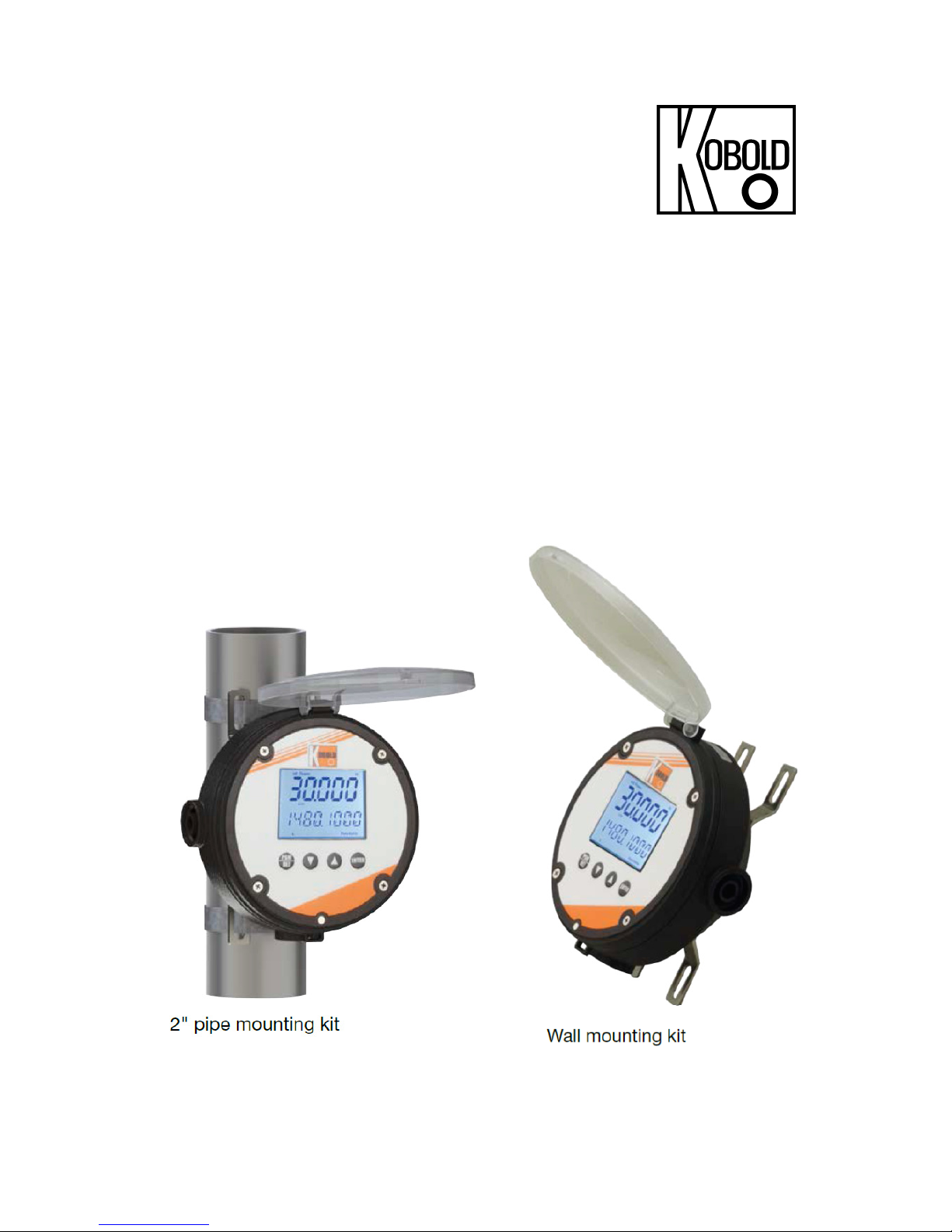
Flow counter/- unit/-- in plastic- universal housing with wall or pipe mounting set
Model: ZOE-ZX with universal housing ‘K’
OR
Oval gear flow meter DON- with electronics option –ZE/ZB in compact version
Model: ZOE-ZX with universal housing ‘M’
Operating Manual
Battery 3.6 V Lithium size AA for battery mode
4. Regulation Use
The electronic units ZOE-ZX are specifically designed for the calculation, display and
transfer of calculations and flow rates of flow meters with pulse or frequency outputs.
The instruments display flow rate, day counter (resettable) and total counter in the
operator-selected units. A menu guides you through the programming of the device
that largely eliminates the requirement of constant usage of operating manual. All
user-specific program settings are retained even when changing the battery.
A trouble-free operation of the device is only guaranteed if all instructions in this
manual are complied. We do not accept any liability for damage caused by failure to
follow these instructions.
5. Environment
The electronic options ZOE-ZX are weather resistant and adequately reflect IP66/67
(NEMA 4X). The electronics are housed in a UV-resistant, glass-filled nylon housing
with stainless steel screws and FPM seals.
The instruments are suitable for harsh indoor or outdoor environments and comply
with EU Directive 2014/30/EU (Electromagnetic Compatibility).
Page 5
ZOE
ZOE K04/0718 Page 5
6. Instrument / Functions overview
Function ZOE-ZExxF3 ZOE-ZBxxFB
Dual counting
function
x x
Supply voltage
DC-supply
x -
Battery operation
x x
Sensor supply (only
with external supply)
8 V -
Electrical outputs (only with external
supply)
Pulse output
x -
LCD Display
Selectable units
x
X
Decimal point
x
X
Accumulated totalizer
x
X
Resettable totalizer
x
X
Linearization
x
X
Rate display
x
X
Backlight
x -
Page 6
ZOE
Page 6 ZOE K04/0718
7. Electrical connections
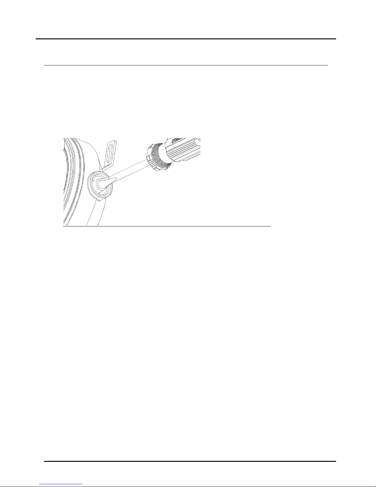
7.1 Cable entry for housing option -K
Up to 3 cable entries (M20x1.5 or ½ "NPT) are available for electric connection in case
of electronics with plastic housing. To use these cable inlets, the existing factory
protection caps must be broken with a tool (e.g. screwdriver) and a suitable cable
gland should be screwed in. The cable glands are not included in the delivery.
Eruption of cable inlets
Page 7
ZOE
ZOE K04/0718 Page 7
Battery 3,6V 2200mAh
Size AA
+ -
ext BattService
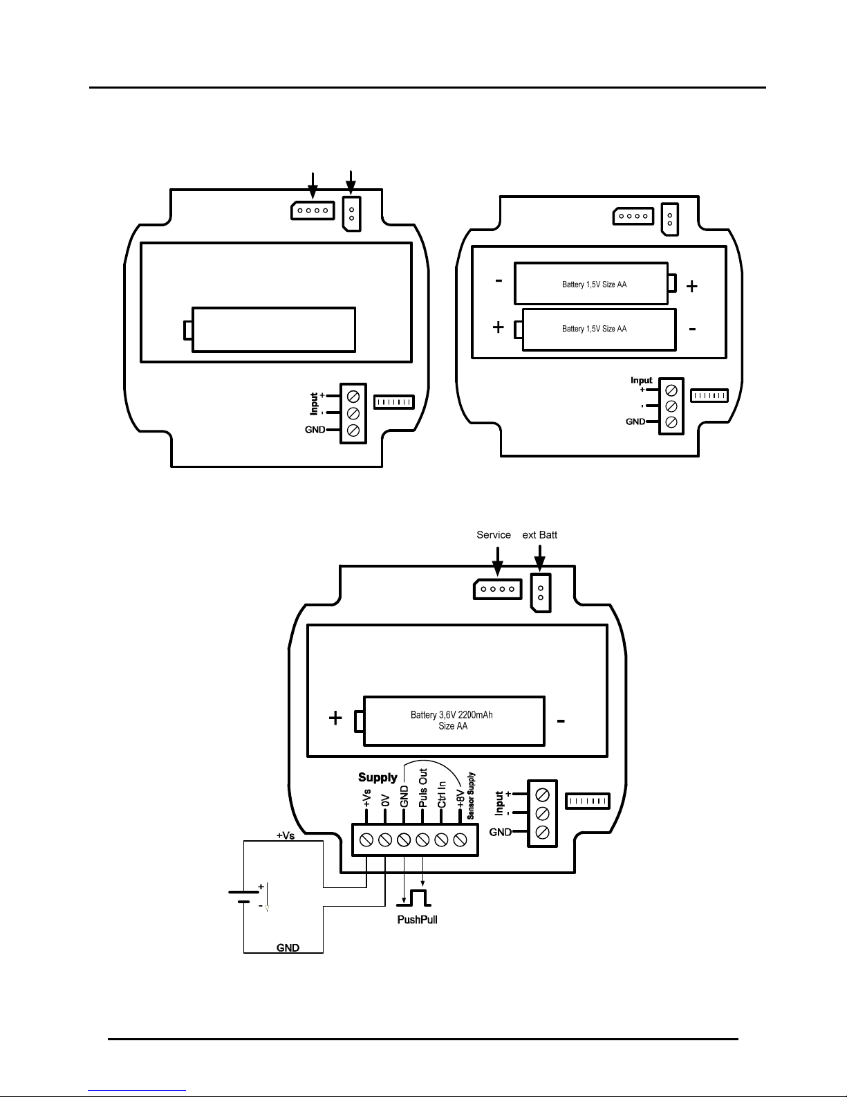
7.2 Overview of Terminals ZOE-ZX with Supply option B and 3
Supply option B (only battery- either 1 x 3,6V or 2 x 1,5V)
Supply option 3 (with battery- either 1 x 3,6V or 2 x 1,5V and external supply)
Page 8

ZOE
Page 8 ZOE K04/0718
7.3 Power Supply
Depending on functionality and features, the electronics offer different possibilities for
power supply:
Options ZOE-ZExxx3xx: Battery and ext. DC-Supply
Options ZOE-ZBxxxBxx Battery operation
7.3.1 Storing the counter readings
The storage of meter readings is carried out after each measurement cycle in the
internal FRAM. If the power is interrupted and re-applied, than the meter reading revert
to the last saved values.
7.3.2 External DC-Supply
When electronic units are supplied with external DC voltage, all functions are available
i.e. Pulse output, display backlight and sensor supply can be used as needed.
If the device is taken out of operation and not used for longer periods,
the battery must be removed. Otherwise, the device is always supplied
by the battery and remains active. As a result, the battery can get
discharged.
7.3.3 Battery operation (ZOE-ZB with supply option B)
The option ZOE-ZX can also be powered by a battery. In battery mode, the device
function scope is relatively limited:
Pulse output is not available.
The backlight of the display is switched off and cannot be turned on.
Only passive sensors may be used like reed switches, as they require no
additional power supply. Usage of induction coils reduces the battery life. Other
sensors, which require a sensor power for operation, are also not suitable for
battery operation.
The supplied battery type 3.6 V AA Lithium (2200 mAh) should be inserted in the
battery holder on the back side of the electronic (correct polarity is important!).
The following type of battery is required as a replacement for the supplied battery:
3.6 V lithium, size AA, capacity at least 2200 mAh, IEC type CR14505
For example: EVE type ER14505M, SAFT LS14500, Emmerich ER 14505, VARTA CR
14505
Battery life duration: The achievable battery life is dependent on various factors:
On the total number of detected input pulses and the input frequency(higher
frequencies reduce the battery life)
On the environmental conditions - low temperatures reduce the usable battery
capacity.
Page 9
ZOE
ZOE K04/0718 Page 9
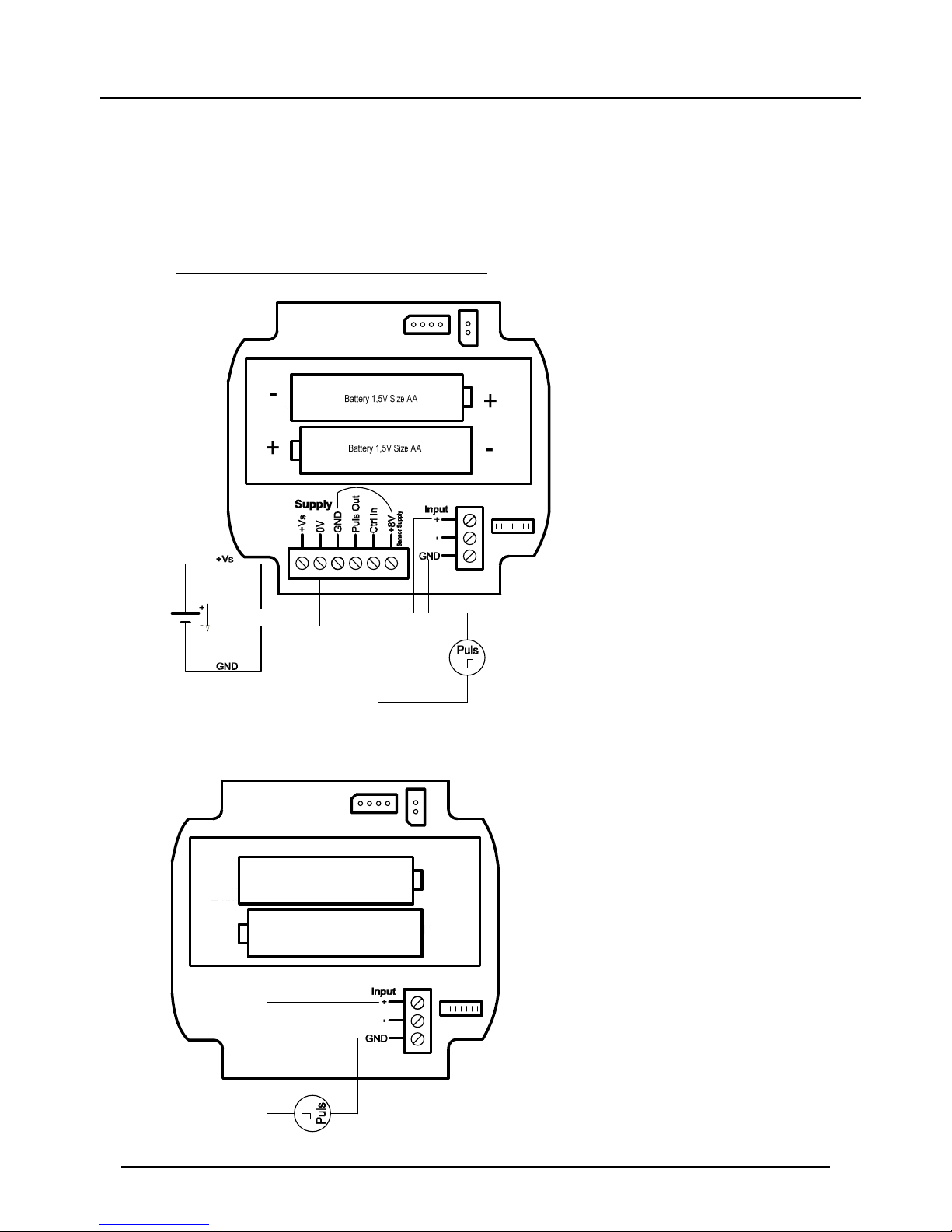
7.4 Sensor Inputs
7.4.1 Active pulse signal
Power Supply: External DC-Supply
Signal input setting: „ACTIVE SIGNAL“
Wiring for ZOE-ZE with Supply option 3:
Wiring for ZOE-Z with Supply option B:
+ -
Battery 1,5V Size AA
+
-
Battery 1,5V Size AA
Page 10
ZOE
Page 10 ZOE K04/0718
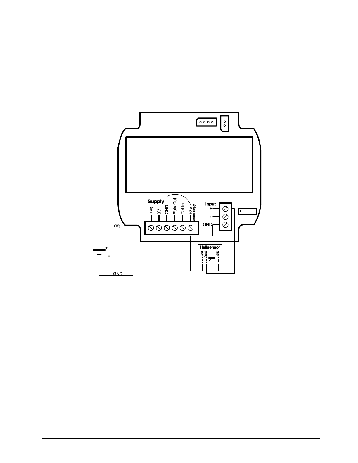
7.4.2 Hall Sensor, NPN- and PNP-Sensors
Power supply: only external DC-supply
Signal input setting: „HALL“
Signal input setting: „NPN“
Signal input setting: „PNP“
Wiring for ZOE-ZE:
Page 11
ZOE
ZOE K04/0718 Page 11
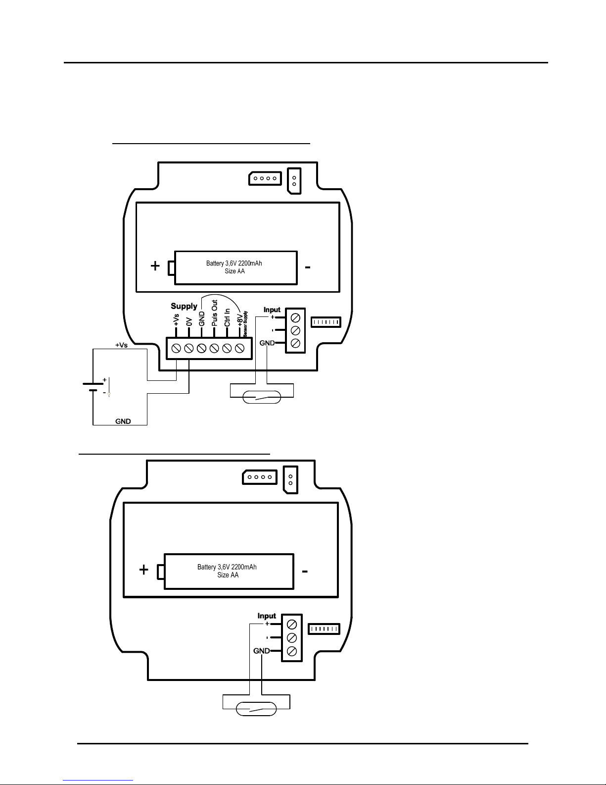
7.4.3 Reed switch
Signal input setting: „REED “
Wiring for ZOE-ZE with Supply option 3:
Wiring for ZOE-Z with Supply option B:
Page 12

ZOE
Page 12 ZOE K04/0718
7.4.4 Self exciting Coil
Power supply: External DC-supply and battery operation
(Battery operation reduces battery life)
Signal input setting: „COIL“
Wiring for ZOE-ZE with Supply option 3:
The connection of the DOT (turbine wheel flowmeter) is identical to the connection of
the induction coil.
Page 13

ZOE
ZOE K04/0718 Page 13
7.4.5 Namur-Sensor
Power supply: only external DC-supply
Signal input setting: „NAMUR“
Wiring for ZOE-ZE with Supply option 3:
Battery 3,6V 2200mAh
Size AA
+ -
Page 14

ZOE
Page 14 ZOE K04/0718
7.4.6 Transducer model UMF2
Power supply: only external DC-supply
Signal input setting: „NPN“
Wiring for ZOE-ZE with Supply option 3:
5 4
Battery 3,6V 2200mAh
Size AA
+ -
Page 15

ZOE
ZOE K04/0718 Page 15
7.4.7 PMG (magnetic inductive with frequency output)
Supply Voltage: only external DC power supply
Signal input setting: PNP
Wiring for ZOE-ZE with Supply option 3:
7.5 Control Input
There is one control input available for external controlling of instrument functions. The
activation of its function can be done through:
a.) an active control input or
b.) Carried out by a passive N/O contact.
In both cases, the function will be activated on switching from HIGH to LOW level
(falling edge).
When using an active control signal, the signal amplitude of the HIGH level must be
from 5 to 30Vdc. When using simple normally open contact, the input potential is
internally pulled of HIGH, if the contact is open. If the contact is closed, the input
potential is pulled to GND and the control function is activated.
Function of control input:
Control input ZOE-ZX
CTRL1
Page 16

ZOE
Page 16 ZOE K04/0718
Wiring for ZOE-ZE with Supply option 3:
Battery 3,6V 2200mAh
Size AA
+ -
Page 17
ZOE
ZOE K04/0718 Page 17
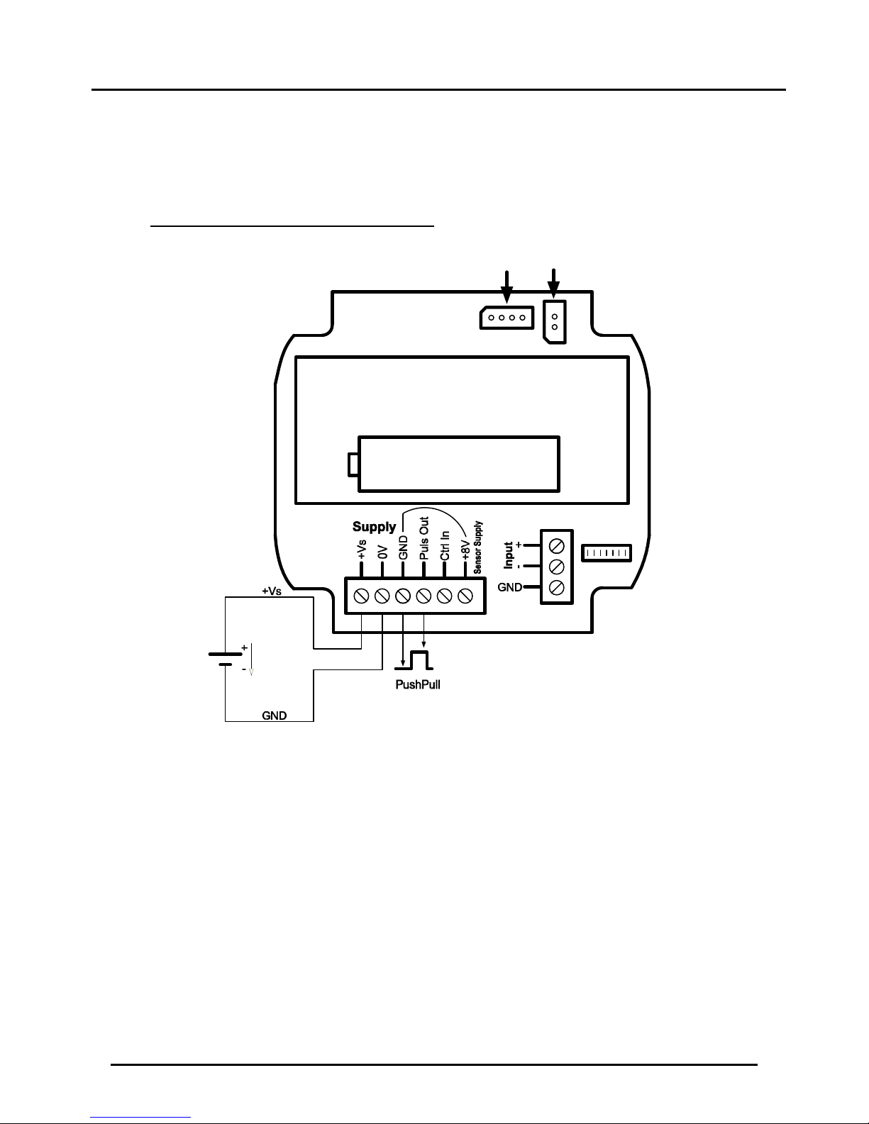
7.6 Pulse Output
Pulse output is set to push-pull output type and provides an active digital signal with
HIGH amplitude of about + Vs.
Wiring for ZOE-ZE with Supply option 3:
Battery 3,6V 2200mAh
Size AA
+ -
ext BattService
Page 18

ZOE
Page 18 ZOE K04/0718
8. Operating and Menu Structure
8.1 Overall
Functions of operating buttons
Button Symbol
Function
Measuring mode Menu mode
Menu / Return
Enter Menu mode
To be pressed
for 3-5 sec
During the parameter setting,
back to main menu / return to
the measurement mode/jump
to the previous decimal
position while setting
numerical values
Down n.A.
Menu item selection /
incrementing and
decrementing digits while
setting numerical values on
the display
Top n.A.
Enter n.A.
Numerical input: Jump to the
next decimal position
General: Saves the
parameter value and returns
to the parent menu
8.2 Measuring Mode
After applying the supply voltage, the electronics starts in measurement mode. In this
mode, the input signals are recorded continuously; current instantaneous flow and
volume counter readings are periodically calculated and displayed.
On LCD, in addition to main display, the status and configuration of the pulse output
and supply voltage are also displayed.
8.2.1 Display range of the Volume Counter
The number of digits that appear on the display for volume counter (partial and total
volume counter) is limited to maximum 8 digits. If 8-digit display range is exceeded,
the display will signal/represent it by displaying 8 hyphen signs (--------). In this case,
the counter cannot be read. The user has then the possibility of changing the Unit of
the volume counter in the Volume Menu so that the counter values can be brought
back again within the display range.
Page 19

ZOE
ZOE K04/0718 Page 19
8.2.2 Display layout in measuring mode (ZOE-ZX)
8.3 Menu Mode
8.3.1 General
In the menu, all device parameters can be set. The individual parameters are
organized into groups according to their function. While the menu mode is turned on,
the input signal detection and pulse output are still active in the background. After
leaving the menu mode, all display parameters are then updated again in
measurement mode.
Note: The menu mode is not exited automatically even after a certain time without key
operation. The menu mode remains active (in battery mode) until the user has once
pressed the button.
In battery mode, a long stay in menu mode shortens battery life.
Page 20

ZOE
Page 20 ZOE K04/0718
8.3.2 Parameter setting
Measuring mode Menu mode-Main group
3-5 seconds
Menu mode Parameter selection mode-Sub group
To activate the Menu mode, the button must be pressed for 3-5 sec. The
parameters are divided into main groups and subgroups. For selection of main groups,
and buttons are used. In the main menu, all menu groups can not be
displayed simultaneously on the screen so the list of menu items can then be scrolled
up or down. To choose the selected item, button should be pressed and the
device goes into relevant sub-menu i.e. into the parameter setting level. For selection
of predefined parameter values, and buttons are used. After changing
the value of the parameter, button should be pressed to save it and to return to
the previous menu level. The return to the main menu or exit to the menu mode takes
place by repeatedly pressing .
Page 21

ZOE
ZOE K04/0718 Page 21
8.3.3 Numerical value input
While setting parameters with numerical value, the value to be set is always displayed
above the parameter. The maximum size and the number of decimal places are fixed
and cannot be changed. While setting the numerical value of a parameter, the left
outer position starts blinking first indicating the position of the cursor. These positions
can be assigned with numbers from 0 to 9 with the help of buttons. By
pressing button, the input cursor moves to right and the next digit can be
changed. In case of a false entry at the previous position, the cursor can be moved
again to left by pressing key and the correction can be made. If the cursor is on
the far right, the set value is saved by pressing the button and the display
changes to the parent menu.
9. Instrument Parameters
9.1 End of instrument parameterization
All ZOE-ZX electronics options are preconfigured at the factory when ordered with
Oval Gear meter. A change in the parameters of the menu groups "Signal Input" and
"Rate measurement" should not be made.
With subsequent changes of volume or flow rate units, dependent parameters will be
converted and adapted accordingly.
In a basic scaling, all parameters of the menu groups "Scaling" and "Rate" must be
edited successively.
An accidental change of configuration can be restored through “Factory defaults’’
function in User Service Reset.
Page 22

ZOE
Page 22 ZOE K04/0718
9.2 Overview of menu functions/ instrument parameters
Menu
level
Sublevel Parameter level Description
Value
range
Default
value
available
with voltage
type
DISPLAY
LIGHT [Digits]
Display
brightness
0 - 100
(Step
size 10)
100 external
LIGHTOUT [Digits]
Time out of
backlight
0-30 s
(Step
size 1s)
0 (No
timeout)
external
LAYOUT
PA - tO Part - Total
List
selection
[default] Battery,external
tO - PA Total - Part
rA - PA Rate - Part
PA - rA Part - Rate
rA - tO Rate - Total
tO - rA Total - Rate
rA - AL
Rate Alternating
AL - rA
Alternating Rate
AL - tO
Alternating Total
PA - AL Part - Alternating
SIGNAL
TYPE
nPn
For NPN
sensors
List
selection
[default]
Battery,external
COIL
For induction
coils
Battery,external
PnP
For PNP
sensors
Battery,external
ACt
For active pulse
signals
Battery,external
nAm NAMUR Sensor Battery,external
rEEd
For Reed
sensors
Battery,external
HALL For Hall sensors Battery,external
TIMEOUT [Digits]
Input signal
timeout
2 – 20 s
(Step
size 1s)
[2 s] Battery,external
FIL. FTR [Digits] Filter Size
1-50
(Step
size 1)
1 Battery,external
JMP. TH [Digits]
Jump threshold
for jump-detector
function
0,05 –
1,00
0,1 [xFS] Battery,external
JMP. FTR [Digits]
Factor for jump
detector
confirmation
1-25 1 Battery,external
HWFILTER Hardware filter
ON /
OFF
OFF Battery,external
SCALING UNIT
ml, L, m3, galUS,
galUK, User
Volume unit for
scaling factor
List
selection
L Battery,external
Page 23

ZOE
ZOE K04/0718 Page 23
LIN. PTS [Digits]
Number of
linearization
points
0 - 9 0 Battery,external
Q0 [Digits]
Flow rate for K0
when LIN. PTS
set to 0
Battery,external
K0 [Digits]
Scaling factor
when LIN. PTS
set to 0
[lmp/USERUNIT]
60 Battery,external
RATE
M RATE [Digits]
Measurement
repetition rate
1 – 10
[s]
1 Battery,external
UNIT
ml/m, L/m, L/h,
m3/h, galUS/m,
galUS/h,
galUK/m,
galUK/h, User
Unit for flow rate
measreument
List
selection
L/m Battery,external
START [Digits] MA-value [User] 00000.000 Battery,external
END [Digits] ME-value [User] 00100.000 Battery,external
OVERFLOW [Digits]
Allowable range
can exceed to
overflow value
0 -100
[%FS]
10 Battery,external
COUNTER
UNIT
mL, L, m3, galUS,
galUK, User
Volume units for
counter
List
selection
L Battery,external
RST PART -
Reset subset
counter A
Button
selection
Yes / No
No Battery,external
PULSE
ACT -
Enables/disables
pulse output
Button
selection
Yes / No
No external
VOLUME [Digits]
Input volume per
output pulse in
[L]
[Volume
unit]
1.000 external
UNIT
mL, L, m3, galUS,
galUK, User
sets volume unit
for pulse output
List
selection
L external
WIDTH [Digits]
Sets the pulse
width of pulses
1ms-20s 2ms external
USR
SERV
PASSWORD
Changes user
password
5-digit
number
(00000
=> open
access)
0 Battery,external
RESET
Reset the device
to factory
settings
Battery,external
FAC.
SERV
Password protected - reserved for factory settings
INFO
STAT Displays counter reading Battery,external
VERSION Displays Firmwareversion Battery,external
Page 24

ZOE
Page 24 ZOE K04/0718
9.3 Signal
9.3.1 Signal / Sensor type
The pulse input can be optimally customized to different sensor types in Menu, so that
at the time of connection no further additional wiring is required for correct function.
Menu Parameter Sensor type Internal wiring
NPN Hall sensor, Reed switch and all NPN
sensors
Pull-Up resistor
Coil For induction coil
(Amplitude > 20 mVpp)
High impedance input
PNP For all PNP-Sensors Pull-Down resistor
Active signal For all sensors with active output signal,
e.g. (push-pull outputs)
NAMUR For sensors with 2-wire interface according
to EN 60947-5-6 (NAMUR)
Pull-Down resistor 1kOhm
Reed Reed switch Pull-Up resistor
Hall For Hall sensors Pull-Up resistor
9.3.2 Signal / Timeout
For the detection of input signals, the period duration of signal is determined within a
measuring cycle i.e. Refresh time. However, if within the "refresh time" the input period
is not complete i.e. if the input signal has a frequency lower than the frequency
determined from the ‘’Refresh time’’, then the flow indicator is set to "0". In the shortest
"refresh time" of 1 seconds, only a minimum input frequency of 1 Hz is recorded. In
order to detect even lower frequencies, "Input Timeout" parameter can be configured
up to 20 s. After the completion of „Refresh time“, the signal processing waits for the
full input period until the additional waiting period is expired. It should be noted that by
increasing the waiting time, the reaction time for the detection, for example, a flow
failure is greatly increased. The "Input Timeout" should only be large enough so that
the smallest frequency signal from the connected sensors can be detected.
9.3.3 Signal / Filter
In case of discontinuous input signals, the integrated filter function can filter the display
of flow rates, the analogue output and the switching outputs (only options E3/). Despite
filtering effect, the reaction time to rapid changes in the flow rate can be kept low by
appropriate choice of filter parameters.
The time base for the filtering function is the "Refresh time". The filter function
operates on the principle of "moving average", where the parameter "filter factor"
specifies the number of measuring values which are used to calculate the current flow
value.
If "filter factor" is set to "1", the filter function is virtually eliminated.
For example : „Filterfactor“ = 3, „Refreshtime= 1,0s
Filtered measured value =
Current measured value + Previous measured value + Last to the previous measured value
3
The correct flow value is displayed after 3 x 1 =3 s.
Page 25

ZOE
ZOE K04/0718 Page 25
In addition, a jump detector is integrated in the filter function, which monitors whether
the current measured value has greatly changed compared to the last filtered
measured value. With the parameter "jump threshold", the level of threshold is defined.
If this „jump threshold „ is exceeded, the filter function is bypassed depending on
parameter „jump factor“, thus achieving a faster response time with respect to rapid
changes in flow.
The triggering of jump detector due to fluctuations in measurement value can be
prevented by setting the "jump factor" > 1.
In addition to the software filter, an analogue low-pass filter with menu ‘Hardware filter’
can be simultaneously connected at two output signals if required.
The connection is useful when the input signal is affected by higher frequency noise
and this can lead to an unstable flow indication.
In case if 'Reed' is chosen as sensor under 'Sensor type' Menu, then the hardware
filter will be automatically activated. In case of other sensors, it is by default inactive
and can be activated by the user anytime using Menu.
9.4 Scaling
The correct scaling of the signal inputs is necessary for exact indication on the display.
For this purpose, entering the pulse rate of the connected sensors is necessary. For
ZOE-ZX in single-channel mode for input A linearization function with up to 10 points is
available. The linearization function is not available in dual channel mode!
The linearization function linearizes the flow indicator, volume counters and thereon
dependent outputs (analogue output and switching outputs).
The pulse output in principle cannot be linearized and will always be calculated with
the pulse rate of scaling point K0.If the linearization function is disabled and only
scaling point K0 is active, the curve is linear and goes through "0" and point K0 (see
graph).
For a linear function, it is not necessary to enter input parameter "flow rate K0". The
"flow rate Kx" parameter is only required for the determination of the reference points
when using the linearization function.
Points for the linearization function
Linearisation deactivated
Page 26

ZOE
Page 26 ZOE K04/0718
Linearization Incorrect!
Flowrate Ax
negative slope!
With active linearization function, the number of linearization points for parameter
„linearization points“(in addition to point A0) is set fixed. Depending on the setting of
this parameter, the other input parameters are shown in the menu. Input signals above
the last point linearization are processed with the pulse rate of the last point.
Conditions for the base sequence:
The sensor curve must be monotonically increasing, since the frequency values
increase continuously with increasing flow.
Inconsistent base sequence
After entering the linearization points, a check is carried out for consistency when the
user exit the menu item "Signal Input".
Should one or more bases not comply with the Terms Security for the base sequence,
the below message box appears:
Such a case is illustrated in the graph below, in which Q2 <Q1, thus having a
negative slope between K2 and K1.
To correct this error, the bases must be checked and corrected if necessary. This
must always apply:
Page 27

ZOE
ZOE K04/0718 Page 27
9.5 Rate
9.5.1 Rate / Measuring rate
Parameter "Measuring rate" specifies the time interval within which the input signal is
recorded, the flow rate is calculated and brought to display. The condition of all other
outputs which depends on the flow rate (analogue output, switching outputs and status
output) will be recalculated after the measurement time.
The "sampling rate" can be increased in steps of 0.5 sec. up to 10 sec. An increase in
the sampling rate time on one hand causes increase in the filtering time of the input
signals, but also an increased reaction time in the detection of changes in the flow
values.
9.5.2 Rate / Unit
The unit displayed for the flow rate measurement can be selected from various
predefined standard units. The definition of a user-defined unit ("User") is possible,
here the „User Unit “must be programmed in Liter/min.
e.g.:
Unit: user = 100 LPM, if flow = 500 LPM then the flow rate shown on display will be 5
user.
9.5.3 Rate / Start
The parameter "start point" defines the lower flow rate limit for display and further
evaluation. If the measured flow rate lies below the measuring range value, the flow
rate is set to "0", therefore "hidden". At the same time the "underflow" icon will appear
in the display.
If the value of the parameter is set to "0", this feature is effectively disabled.
9.5.4 Rate / End
With parameter "End point", the upper measurement limit of the connected sensors /
transducers is set.
Depending on the actual flow display, the decimal point for the bigger display adjusts
itself automatically.
Flow Display Decimal points on
the Display
0.1 to 9.9999 4
10 to 99.999 3
100 to 999.99 2
1000 to 9999.9 1
10000 to 99999 0
If the flow rate is displayed on the smaller display, the number of decimal points is
fixed to 4 and cannot be changed. However the digits before the decimal point change
themselves automatically from e.g. 0-9999 [Unit] depending upon the actual flow.
9.5.5 Rate Measurement / Over flow value
The parameter "overflow value" is set in "% of full scale"
Example: "end point" = 100 [L / m], "overflow value" = 10 [%]
The arrow pointing upwards on the top right side of the display will
be shown when flow display shows 110 l/m.
Page 28

ZOE
Page 28 ZOE K04/0718
9.6 Counter
All electronics have options of a (non-resettable) totalizer and a (resettable) partial
totalizer for the connected input. The status of all active counters can be displayed in
the "INFOSTAT" menu.
9.6.1 Counter / Volume Unit
Parameter "volume unit" defines the unit volume of all volumetric counters. There are
listed volume units to choose from. When changing the unit of volume, the actual
meter readings are converted into the new unit volume.
9.6.2 Counter / Part Volume Reset
In this menu you can reset the partial volume counter for ZOE-ZX.
General
The user has the option to display the totalizer/counter values on smaller as well as
the bigger display with the help of different layouts available under ‘DISPLAY’ menu.
However the bigger display is limited to display only 5 digits. If the totalizer consists of
more than 5 digits e.g. 8 digits, it won’t be possible to display the 3 digits.
The problem is solved with the help of scientific notation using power of 10. In this
case, only 5 most significant digits will be displayed. The least significant digits will be
cut off and replaced with exponent showing the total strength of the digits. However
the information processed by the electronics in the background is always accurate and
correct. The display switches between MSB’s and exponent with a rate of 1 sec. e.g.:
Rate
Partial totalizer
Rate
Partial
totalize
r
Exponential part
using scientific
notation
Page 29

ZOE
ZOE K04/0718 Page 29
Since some useful information cannot be displayed in this case, it is recommended to
use a bigger unit to avoid the loss or to use the smaller display for totalizers.
9.7 Pulse output (only with ZOE-ZE Supply option 3)
A scalable pulse output is available for the options ZOE-ZExxxx3xx. When the pulse
output is enabled, a scaled pulse output train is given at the output to the input pulses.
The pulse width of the pulses is adjustable between the span of 1 ms to 20 sec.
When pulse output is activated, the symbol " " for pulse output is highlighted on the
display. The electrical output of the pulse output is push-pull type, so HIGH and LOW
is actively switched through to the output.
To generate the output pulses, the input pulse train is directly processed in connection
with the scaling factor “K0”, the output pulses are therefore not derived from the
calculated volume flow. The pulse output is based on a linear path of the input signal.
Sensors are used with nonlinear characteristic, with the usage of linearization function
only the updated volume flow can be linearized, pulse output and volume counter
cannot be linearized.
Behaviour at OVERFLOW:
If the measured volumetric flow lies in the OVERFLOW range, the pulse output is
switched off and a constant HIGH level is switched at the output.
Generation of the output pulse train:
The maximum adjustable pulse rate for the pulse output is 1000 pulses per liter. This
means that the minimum pulse volume that can be represented by the pulse output is
0.001 Liter per pulse. Furthermore, the set pulse volume must meet following
condition:
∗ 1
100
60 ∗
0.5
In case if the above mentioned condition is not complied with, it may lead to a long
lagged pulse train at pulse output even when the input frequency signal has been
interrupted and removed. While configuring the pulse output, if the above condition is
violated, the user will be informed via notification on the display with “Lagged pulse
train possible. Please check the settings.” In case if the measuring range endpoint is
changed during the operation of pulse output, the user needs to check the pulse
output settings once again.
The pulse output works only in the measurement mode i.e. in the menu mode, no
pulses will be generated at the output. The pulses acquired in the menu mode will be
given out once the normal measuring mode is activated again, leading to no loss but a
delayed pulse train at the output depending on how long the menu mode remains
active.
Page 30

ZOE
Page 30 ZOE K04/0718
9.7.1 Pulse output / Volume
The "pulse volume" parameter is defined as the volumetric amount for the output of a
pulse at the output; the unit is in accordance with [amount of volume / pulse]. The
familiar Pulse rate [pulses / unit volume] corresponds to the reciprocal of the pulse
volume.
Example: Required pulse rate at output 10 Pulse/Liter => Pulse Volume = 1/Pulse rate
= 1/10 L = 0.1 L
9.7.2 Pulse output / Unit
The volume set unit is the input unit for the parameter "Pulse volume". User can also
set a user defined unit which will be given in “Liter”. e.g.:
Unit: user = 10 [Liter], pulse volume = 2 [user]
In this case the pulse will be generated after 2*10 = 20 Liters
9.7.3 Pulse output / Width
The pulse width of pulse output is flexibly adjustable from 1 to 20000 ms.
9.8 User service
Reset function and password activation are available for user in user service menu.
Together with the activation of a user password, the access to menu for the user can
be locked by a master user.
9.8.1 User service / Change password
The default administrator user password is set to "00000", the user functions are thus
freely accessible. If the user's password has been changed from "00000", password
request will be generated on next entry to User menu.
If the default password has been forgotten or misplaced, the master password can be
requested from KOBOLD.
9.8.2 User service / Reset
By activating this function, the user can reset the device to factory settings. All user
settings will be lost and the device will be reset to the factory settings.
9.9 Factory service
The factory service function is password protected and is not available for the user.
9.10 Information
9.10.1 Status
The partial and accumulated totalisers can be seen by the user through this menu
function.
9.10.2 Firmware version
This menu function shows the user the installed firmware version and revision. The
information about firmware version can also be seen when the electronics is first
switched on.
Page 31

ZOE
ZOE K04/0718 Page 31
10. Technical Details
External power supply: 5…30 VDC (without sensor supply)
9…30 VDC (with sensor supply)
power consumption max. 40 mA
(only ZOE-ZExxx3)
Battery for operation: 1 x 3.6 V lithium size AA
or 2 x 1.5 V alcaline cell size AA
Battery life: using 3.6 V lithium with 2200 mAh: up to 5 years
using 2 x alcaline cells with 2600 mAh each:
up to 2 years (at 50 µA)
Display: LC display (for ZOE-ZExxx3 background lighting white)
height of digits for: 5 digits volume flow: 13 mm
8 digits volume counter:
8 mm display of battery power
Mounting options: meter mount, wall or pipe mounting
Measuring input: universal, configurable (NPN, PNP, NAMUR coil, reed
switch or active)
Input frequency 0.1…1000 Hz,
High-low-threshold 0.6 V
DC
Minimum input voltage for coil input: 30 mVpp
Measuring rate: 1 s
Units for volume flow: ml/h, l/m, m3/h, gpmUK, gpmUS, gphUK, gphUS, User
Units for volume counter: ml, l, m3, galUS, galUK, User
Control input
(only ZOE-ZExxx3): for part counter resetting
Linearisation: 1…9 interpolation points, can be deactivated
Accuracy of flow measurement: < 0.1% of reading (depending on scaling and
resolution)
Sensor supply
(only ZOE-ZExxx3): 8 VDC, max. 25 mA (for external supply > 9 VDC)
Pulse output
(only ZOE-ZExxx3): push pull, max. 30 V
DC
, max. 50 mA
Operation: 4 buttons
Housing: plastic, PA6, GF-enhanced
Protection: IP 66/67
Cable entry: 3x M20x1.5 or ½” NPT (prepared)
Electrical connection: plug-in terminals wire size max. 0.75 mm
2
Retention of meter readings
In case of power failure: cyclic, non-volatile memory
Ambient temperature: -20 °C ≤ T
ambient
≤ 80 °C
Storage temperature: -25 °C ≤ T
storage
≤ 80 °C (without battery)
Page 32

ZOE
Page 32 ZOE K04/0718
11. Order Details
Example: ZOE-ZE K M F 3 0 0)
Model Electronics Housing Type
Electrical
connection/
cable gland
Input Power supply Options Special
ZOE-
ZB = rate totaliser
without external
power supply/
with battery
0 = universal mount
(standard, round
plastic without
wall mounting
kit)
K = universal mount
(standard, round
plastic with
holder plates)
M = universal mount
(round plastic
for retrofitting
DON)
M = 3xM20x1.5
cable entry
N = 3x ½” NPT
cable entry
F = pulse/
frequency
input
B
1)
= battery for
operation
0 = without
0 = without
Y = special
(please
specify in
clear text)
ZE = rate totaliser
with external
power supply/
with battery
3
2)
= 9…28 V
DC
battery for
operation,
pulse output
1)
Only available with ZOE-ZB
2)
Pulse output, Sensor supply and LCD backlight only with external power supply. Only available with ZOE-E
Accessories
Description Model
Stainless steel wall mounting kit
ERS-ZOK-023618
Stainless steel 2” pipe mounting kit
ERS-ZOK-003402
Page 33

ZOE
ZOE K04/0718 Page 33
12. Dimensions
[mm]
ZOE-ZXK
ZOE-ZXM
Page 34

ZOE
Page 34 ZOE K04/0718
13. EU Declaration of Conformance
We, KOBOLD Messring GmbH, Hofheim-Ts, Germany, declare under our sole
responsibility that the product:
Flow-Counter/-- Unit/-- Model: ZOE-ZX
to which this declaration relates is in conformity with the standards noted below:
EN 61326-1:2013 Electrical equipment for measurement, control and laboratory
use - EMC requirements - Part 1: General requirements
Also the following EC guidelines are fulfilled:
2014/30/EU EMC Directive
2011/65/EU RoHS (category 9)
EN 50581:2012 Technical documentation for the assessment of electrical and
electronic products with respect to the restriction of hazardous substances
2006/66/EC Directive Batteries and Accumulators
Hofheim, 13. July 2017
H. Peters M. Wenzel
General Manager Proxy Holder
 Loading...