

Kobold ZDM-XX08 Series, ZDM-XX02 Series, ZDM-XX09 Series, ZDM-XX10 Series, ZDM-XX20 Series User Instructions
...Page 1
ZDM Positive Displacement Flow Meter
User Instructions
USA
1801 Parkway View Drive
Pittsburgh, PA 15205
PH 412-788-2830
www.koboldusa.com
Canada
9A Aviation
Point Claire, QC H9R 4Z2
PH 514-428-8090
ZDM_manual_11-10
Page 2

Table of Contents
Topic Page
1.0 General . . . . . . . . . . . . . . . . . . . . . . . . . . . . . . . . . . . . . . . . . . . . . . . . . . . . . . . 1
2.0 Description. . . . . . . . . . . . . . . . . . . . . . . . . . . . . . . . . . . . . . . . . . . . . . . . . . . . . 2
2.1 Principle of Operation. . . . . . . . . . . . . . . . . . . . . . . . . . . . . . . . . . . . . . . 2
2.2 Specifications. . . . . . . . . . . . . . . . . . . . . . . . . . . . . . . . . . . . . . . . . . . . . 2
2.2.1 Mechanical Data. . . . . . . . . . . . . . . . . . . . . . . . . . . . . . . . . . . . . 2
Filtration Requirements. . . . . . . . . . . . . . . . . . . . . . . . 3
Electrical Data. . . . . . . . . . . . . . . . . . . . . . . . . . . . . . . . . . . . . . . 3
2.2.3 Accuracy. . . . . . . . . . . . . . . . . . . . . . . . . . . . . . . . . . . . . . . . . . . 3
2.2.2 Pressure Loss. . . . . . . . . . . . . . . . . . . . . . . . . . . . . . . . . . . . . . . 4
3.0 Installation Instructions. . . . . . . . . . . . . . . . . . . . . . . . . . . . . . . . . . . . . . . . . . . . 4
3.1 Mechanical Installation. . . . . . . . . . . . . . . . . . . . . . . . . . . . . . . . . . . . . . 4
3.1.1 Installing the Mounting Plate. . . . . . . . . . . . . . . . . . . . . . . . . . . . 4
3.1.2 Attaching the Flow Sensor to the Mounting Plate. . . . . . . . . . . . 4
3.1.3 Bolt Torque Specifications . . . . . . . . . . . . . . . . . . . . . . . . . . . . . 4
3.1.4 Connecting Piping to the Sensor . . . . . . . . . . . . . . . . . . . . . . . . 5
3.2 Electrical Connections . . . . . . . . . . . . . . . . . . . . . . . . . . . . . . . . . . . . . . 5
4.0 Operating Instructions . . . . . . . . . . . . . . . . . . . . . . . . . . . . . . . . . . . . . . . . . . . . 6
4.1 Turning the Unit On . . . . . . . . . . . . . . . . . . . . . . . . . . . . . . . . . . . . . . . . 6
4.2 Flow Measurement. . . . . . . . . . . . . . . . . . . . . . . . . . . . . . . . . . . . . . . . . 6
4.3 Turning the Unit Off . . . . . . . . . . . . . . . . . . . . . . . . . . . . . . . . . . . . . . . . 7
5.0 Arrival of Damaged Equipment . . . . . . . . . . . . . . . . . . . . . . . . . . . . . . . . . . . . . 7
6.0 Maintenance. . . . . . . . . . . . . . . . . . . . . . . . . . . . . . . . . . . . . . . . . . . . . . . . . . . . 7
7.0 Need Help with your ZDM Sensor? . . . . . . . . . . . . . . . . . . . . . . . . . . . . . . . . . . 7
Appendix A: Pressure Loss vs. Flow Rate at Various Viscosities . . . . . . . . . . . 9
List of Diagrams
Diagram 3.2.1 ZDM Wiring Schematic. . . . . . . . . . . . . . . . . . . . . . . . . . . . . . . . 5
Diagram 4.2.1 ZDM Frequency Output Waveform. . . . . . . . . . . . . . . . . . . . . . . 6
List of Tables
Table 1: ZDM Wetted Parts . . . . . . . . . . . . . . . . . . . . . . . . . . . . . . . . . . . 2
Table 2: Volume per Pulse for Various ZDM Ranges. . . . . . . . . . . . . . . . 7
Page 3

ZDM
KOBOLD ZDM POSITIVE DISPLACEMENT FLOWMETER
User Instructions
CAUTION: For safety reasons, please read the cautionary information located at
the end of this manual, before attempting installation.
1.0 General
Congratulations on your purchase of a Kobold ZDM Positive Displacement flowmeter.
The ZDM is one of the most precise and reliable low volume, liquid flow measuring
products available today.
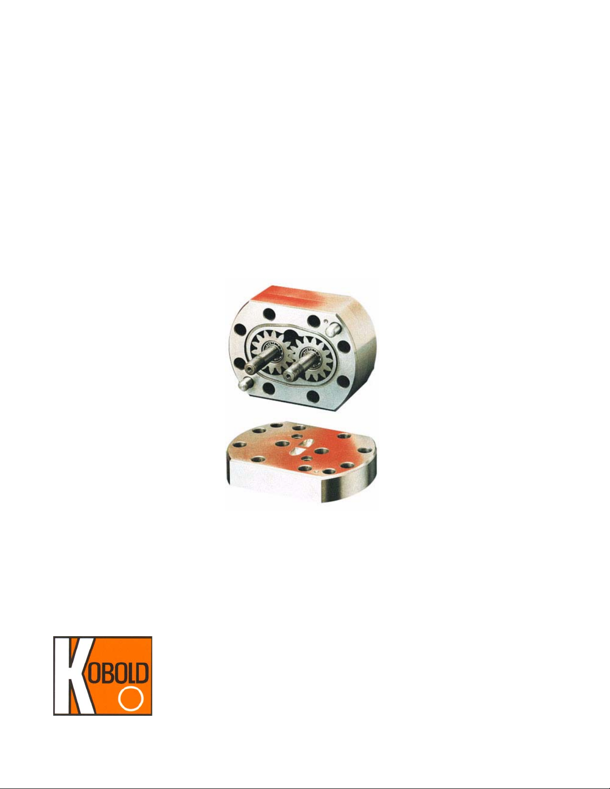
The ZDM operates on the viscosity and density independent volumetric principle. Two
gears are brought into counter-rotation by the force of liquid moving past the gears along
the meter’s housing. Engagement of the gear teeth with the housing walls entraps a
defined volume in the cavity between the gear teeth. A detector counts the gear teeth as
the cavities empty into the exit port. The precision of the meter is defined by the gear
cavity volume. The ZDM can meter volumes as low as 0.02 CC (cubic centimeters.) This
ultra-high precision is coupled with bi-directional flow capability, viscosity compatibility to
100,000 cS t and a mechanical robustness ca pable of pressures to 6500 PSIG (450 BAR).
The ZDM is the ideal choice for difficult clean liquid applications involving media with
lubricating properties ranging from very slight, to extensive.
FM Rev. 11/10
Page 4

ZDM 2
2.0 Description
2.1 Principle of Operation
The ZDM operates on the volumetric displacement principle. The meter moves pocket s of
liquid from the inlet port to the exit port in discrete segments of known volume. These
pockets are defined by the space between adjacent gear teeth and the internal housing
wall.
As liquid enters the meter, the inlet cavity fills. The liquid pressure forces the meter’s
gears to rotate from the gear mesh-point inwards. The ge ar teeth ca vities fill with liqu id in
the inlet side of the meter and remain filled as the teeth come into near-contact with the
meter’s interior walls. The gear teeth then drag the liquid to the exit cavity at the opposite
side of the meter. This process causes the exit cavity to fill since the liquid is squeezed
out of the spaces between the teeth at the gear mesh point. The liquid then flows out the
exit port of the meter.
A proximity sensor in the housing senses the passage of individual gear teeth. Since the
passage of a tooth signals the passage of its trailing space (filled with liquid), the system
as a whole signals with an electrical pulse every time a displaced amount is emptied into
the exit port. The resolution of the ZDM is, therefore, determined by the volume between
the gear teeth.
This entire procedure is completely independent of the properties of the liquid, making the
system applicable to a wide variety of media (even liquids with dynamically changing
characteristics.) The only limitations to the system are mechanical ones. Since metal to
metal contact is involved, the liquid must have some lubricating properties in order to
prevent excessive wear of the gear teeth. If the gear teeth wear down, liquid will leak p ast
them excessively. This excess leakage will degrade the meter’s accuracy. The required
amount of media lubricity is very slight. For example, leaded gasoline (such as jet fuel)
will work, while unleaded gasoline will not.
Another limitation is caused by the relatively high pressure loss inherent to positive
displacement technology. The pressure loss through the ZDM becomes unacceptable if
the media viscosity exceeds 100,000 cSt.
2.2
Specifications
2.2.1 Mechanical Data
Table 1: ZDM Wetted Parts
Nominal Construction Material
Wetted
Component
Housing Cast Iron 316 Ti SS (DIN 1.4571)
Cast Iron
(ZDM-X1XX)
316 Stainless Steel
(ZDM-X3XX)
FM Rev. 11/10
Gears SS* (DIN 1.4122) 316 Ti SS (DIN 1.4571)
Seals
Bearings Carbon Steel Tungsten Carbide
* Alloy content of DIN 1.4122 SS: X 35 Cr Mo 17. No direct AISI equivalent. Similar
to 400 series SS.
FKM (EPDM Optional) FKM (EPDM Optional)
Page 5

3ZDM
Filtration Requirements
ZDM-XX02, -XX04, -XX07: 10 µM (1600 mesh)
ZDM-XX08, -XX09: 20 µM (750 mesh)
ZDM-XX10, -XX20, -XX40: 50 µM (250 mesh)
Maximum Pressure Rating: Cast Iron: 4500 PSIG
St. Steel: 6500 PSIG
Maximum Temperature Rating
Standard: -40 to 248°F
Accuracy: ±0.3% of reading with
viscosity >20 cSt.
Repeatability: ±0.05% of reading
Electrical Data
Sensor Type: Qty. 2 Push-Pull Outputs (Channels A & B)
A & B Signals are 90° out of phase.
Phase difference can be used to determine
flow direction using suitable receiving equipment.
Power Requirements
Voltage (V
): 10-28 VDC
cc
Current: 80 mA max. @ 24 VDC
Power: 1.92 W max. @ 24 VDC
Output Signal
Type: DC voltage pulse
Form: Square wave
Amplitude: Low = GND, High = V
- 1.0 VDC
cc
FM Rev. 11/10
Page 6

ZDM 4
2.2.2 Pressure Loss
Pressure loss is a function of the viscosity of the liquid being metered, and
its rate of flow. Detailed pressure loss information may be found in
Appendix A of this manual.
3.0
Installation Instructions
CAUTION: For safety reasons, please read the cautionary information located at
the end of this manual, before attempting installation.
3.1 Mechanical Installation
The ZDM is shipped from the factory in two pieces (not counting the electrical
connecting cable or the sensor-mounting plate fastening bolts) consisting of the
mounting plate and the sensor body. We recommend that you install the mounting
plate first, then attach the sensor and finally connect the piping.
3.1.1
3.1.2
Installing the Mounting Plate
The sensor may be rigidly held in place on your installation through use of
the four threaded holes in the base of the mounting plate. These holes are
metric and sized as follows:
ZDM-XX02 to ZDM-XX08: M6 (6 mm metric)
ZDM-XX09 to ZDM-XX40: M8 (8 mm metric)
Attaching the Flow Sensor to the Mounting Plate
The sensor comes supplied with a set of four steel bolts and O-rings for
fastening the sensor to the mounting plate.
3.1.2.1 Install the O-rings into the grooves in the body of the sensor.
3.1.2.2 Position the sensor on the mounting plate so that the bolt holes in
the sensor line up with the bolt holes in the mounting plate.
3.1.2.3 Insert the bolts into the bolt holes and thread into mounting plate
until they are finger tight.
3.1.2.4 With an appropriately sized wrench, tighten the bolts to the specified torque in a diagonal bolt tightening pattern.
3.1.3
Bolt Torque Specifications
The following are the nominal torque specifications for all ZDM bolts.
Meter Model
ZDM-XX02 to ZDM-XX08:40 29.5
ZDM-XX09 to ZDM-XX20:70 51.6
ZDM-XX40: 120 88.5
Torque (N-m) Torque (lb.-ft.)
FM Rev. 11/10
Page 7

5ZDM
3.1.4 Connecting Piping to the Sensor
The procedure for attaching piping to the sensor depends on the type of
thread that was ordered with the sensor. The most common thread in
North America is NPT (series ZDM-3XXX and ZDM-4XXX sensors.)
Occasionally, the European pipe thread (BSP) is ordered because of its
superior leak resistance. Series ZDM-1XXX and ZDM-2XXX sensors all
have BSP threaded fittings.
If the fittings on your ZDM are incorrect for your application, you can
correct the situation by purchasing a different mounting plate.
3.1.4.1 If you have NPT threads, coat the threads with a paste type pipe
sealant before threading into the mounting plate.
We recommend that PTFE tape NOT be used since pieces of it
may find their way into the sensor, possibly causing the gears to
bind. Should you have no alternative to PTFE t ape, make sure tha t
it is properly trimmed and does not extend beyond the first thread
on your pipe fittings.
3.1.4.2 If you have BSP threads, place the sealing gaskets over the ends
of your pipe fittings and thread fittings into the mounting plate.
3.2
Electrical Connections
The standard ZDM operates on a power supply of: 10-28 VDC.
Diagram 3.2.1:
ZDM Wiring Schematic
FM Rev. 11/10
Page 8

ZDM 6
4.0 Operating Instructions
4.1 Turning the Unit On
Supply power.
4.2
Flow Measurement
The ZDM transmits a frequency based electronic signal in response to flow
through its mechanism. This signal takes the form of a square wave, the
amplitude of which is the supply voltage (V
) minus 1.0 VDC. A representation of
cc
the waveform is given in Diagram 4.2.1, "ZDM Frequency Output Waveform", on
page 6. Each pulse in the transmitted signal represents a fixed quantity of liquid
passing through the meter. The exact amount of liquid represented by each pulse
is a function of the range of the meter. To determine the sensitivity of your meter,
consult Table 2, "Volume per Pulse for Various ZDM Ranges", on page 7.
Diagram 4.2.1:
ZDM Frequency Output Waveform
FM Rev. 11/10
Page 9

7ZDM
Table 2: Volume per Pulse for Various ZDM Ranges
ZDM Model Number Range (GPM) Frequency(Hz) Pulses per Gallon
ZDM-XX02 0.0005 - 0.53 1.577-1671. 90 189,272
5.0
ZDM-XX04 0.0011 - 1.
ZDM-XX07 0.0026- 2.
ZDM-XX08 0.0053 - 4.
ZDM-XX09 0.0079 - 10.57 1.
ZDM-XX10 0.0132 - 2
ZDM-XX20 0.0
ZDM-XX40 0.
264
2642
-
-
06
64
76
1.13
31.70
66.00
1.
735
-1671.
90
1.640-1665.
1.672-1501.
246
0.833-1333.
0.833-1
4.167-1041.
59
56
-1667.17 9,463.
11
000.00
00
94,63
37,854
18,927
3,785.4
1,892.7
946.3
6
.4
.2
6
4
2
6
4.3 Turning the Unit Off
Remove power.
Arrival of Damaged Equipment
Y our in strument was inspected prior to shipment and found to be defect-free. If damage is
visible on the unit, we advise that you carefully inspect the packing in which it was
delivered. If damage is visible, notify your local carrier at once. The carrier is liable for a
replacement under these circumstances. If your claim is refused, please contact
KOBOLD Instruments.
6.0
7.0
Maintenance
The ZDM is continuously lubricated by the medium flowing through its internal
components, so no extra lubrication is required.
Please note the following typical filtration requirements:
ZDM-XX02 to ZDM-XX07: 10 um
ZDM-XX08 to ZDM-XX09: 20 um
ZDM-XX10 to ZDM-XX40: 50 um
Make sure that the filter is kept in proper functioning condition. The frequency of filter
replacement and maintenance will depend on the level on cleanliness of the metered
liquid.
The only wear component in the ZDM are the gear teeth. The gear teeth will wear with
time. The rate of wear depends on the time of operation and the abrasion/lubrication
properties of your measured liquid. We recommend that users perform a periodic (every
six months is suggested) check of the meter calibration. The most effective way to do this
is to use a calibrated container, a timer and accurate weight scale.
Need Help with your ZDM Sensor?
Call one of our friendly engineers at 412-788-2830.
FM Rev. 11/10
Page 10

9ZDM
Appendix A:
Pressure Loss vs. Flow Rate
at Various Viscosities
FM Rev. 11/10
Page 11

ZDM 10
FM Rev. 11/10
Page 12

11 ZDM
FM Rev. 11/10
Page 13

ZDM 12
FM Rev. 11/10
ZDM-0010 Pressure Loss
Page 14

13 ZDM
FM Rev. 11/10
Page 15

15 ZDM
CAUTION
PLEASE READ THE FOLLOWING WARNINGS BEFORE ATTEMPTING
INSTALLATION OF YOUR NEW DEVICE. FAILURE TO HEED THE
INFORMATION HEREIN MAY RESULT IN EQUIPMENT FAILURE AND
POSSIBLE SUBSEQUENT PERSONAL INJURY.
FM Rev. 11/10
Page 16

ZDM 16
• User's Responsibility for Safety: KOBOLD manufactures a wide range of
process sensors and technologies. While each of these technologies are
designed to operate in a wide variety of applications, it is the user's
responsibility to select a technology that is appropriate for the application,
to install it per these installation instructions, to perform tests of the
installed system, and to maintain all components. The failure to do so could
result in property damage or serious injury.
• Proper Installation and Handling: Use a proper sealant with all
installations. Never overtighten fittings. Always check for leaks prior to
system startup.
• Wiring and Electrical: A supply voltage of: 10-28 VDC is used to power
the ZDM. The sensor systems should never exceed this rating. Electrical
wiring of the sensor should be performed in accordance with all applicable
national, state, and local codes.
• Temperature and Pressure: The ZDM is designed for use in media
temperatures from -40 to 248°F, and for use at pressures up to 6500 PSIG,
depending on model. Operation outside these limitations will cause
damage to the unit and possible personal injury.
• Material Compatibility: Check your model number with the wetted
materials specifications of this manual. Make sure that the model which
you have selected is chemically compatible with the application liquids.
While the electronics housing is liquid resistant when installed properly, it is
not designed to be immersed. It should be mounted in such a way that it
does not normally come into contact with fluid.
• Flammable, Explosive and Hazardous Applications: The ZDM with
option Ex or EXA are intrinsically safe and are the only units which are to
be used in hazardous locations. Other ZDM models should not be used in
areas where an explosion proof design is required.
• Make a Fail-Safe System: Design a fail-safe system that accommodates
the possibility of switch or power failure as well as operator error. In critical
applications, KOBOLD recommends the use of redundant backup systems
and alarms in addition to the primary system.
FM Rev. 11/10
 Loading...