

Kobold VKP Series, VKP-1035, VKP-1100, VKP-2018, VKP-2030 Operating Instructions Manual
...Page 1
Operating Instructions
for
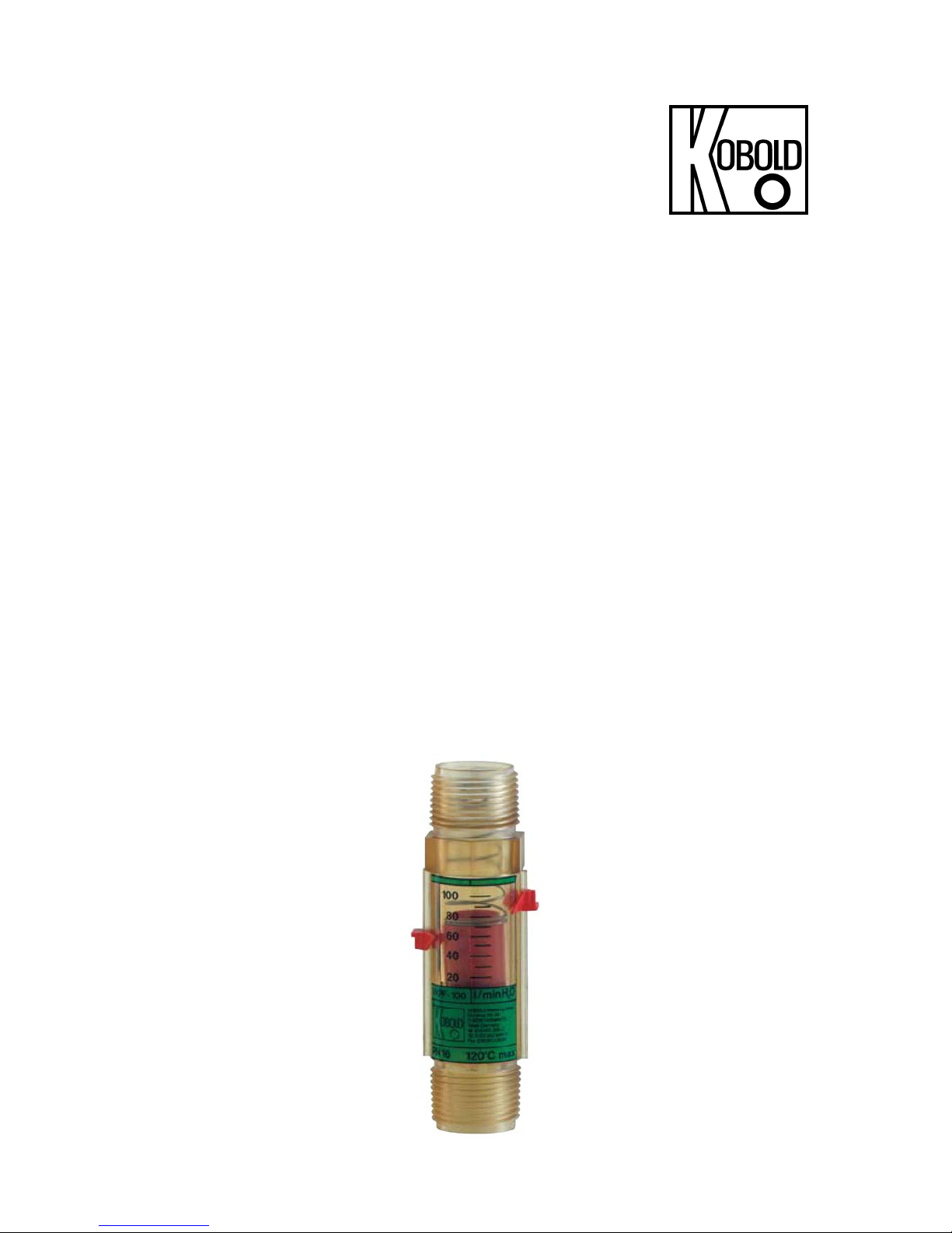
Plastic
Flow Meter and Monitor
(viscosity compensated)
Model: VKP
Page 2

VKP
page 2 VKP K02/0416
1. Contents
1. Contents ........................................................................................................ 2
2. Note .............................................................................................................. 3
3. Suggested Application .................................................................................. 3
4. Operating Principle ........................................................................................ 4
5. Instrument Inspection .................................................................................... 4
6. Mechanical Connection ................................................................................. 5
7. Electrical Connection .................................................................................... 5
8. Commissioning .............................................................................................. 6
9. Technical Information .................................................................................... 7
10.Order Codes ................................................................................................. 8
11.Maintenance ................................................................................................. 8
12.Dimensions ................................................................................................... 9
13.Recommended Spare-parts .......................................................................... 9
14.EU Declaration of Conformance .................................................................. 10
Manufactured and sold by:
Kobold Messring GmbH
Nordring 22-24
D-65719 Hofheim
Tel.: +49(0)6192-2990
Fax: +49(0)6192-23398
E-Mail: info.de@kobold.com
Internet: www.kobold.com
Page 3

VKP
VKP K02/0416 page 3
2. Note
Please read these operating instructions before unpacking and putting the unit
into operation. Follow the instructions precisely as described herein.
The devices are only to be used, maintained and serviced by persons familiar
with these operating instructions and in accordance with local regulations applying to Health & Safety and prevention of accidents.
When used in machines, the measuring unit should be used only when the
machines fulfil the EC-machine guidelines.
as per PED 2014/68/EU
In acc. with Article 4 Paragraph (3), "Sound Engineering Practice", of the
PED 2014/68/EU no CE mark.
Diagram 8, Pipe, Group 1 dangerous fluids
3. Suggested Application
These units of type VKP are employed for flow measurement and monitoring of
H20 and viscous liquids in an economical way.
Only such liquids can be measured which are doped with impurities to a small
extent, and can withstand against the material used for fabrication of housing.
Significant errors in measurement may result if these devices are used for the
measurement of high-viscous media. Large-size impurity-particles may lead to
blockage of float element and thus are subjected to measurement-errors and
error-indications. The same problem may arise if ferrite particles deposit on float
element (with magnets).
These units are configured as follows:
Flow Measurement
The flow reading of the current value of flow is displayed on the scale sticked on
the housing. The upper edge of the float indicates the flow value.
Limit-value contacts (Option)
For the monitoring of the flow value the flowmeter can be equipped with an
adjustable limit switch.
N.O. function (increasing flow)
or N.C. function (increasing flow)
This contact is adjustable over the complete measuring range.
Page 4

VKP
page 4 VKP K02/0416
Materials
Material Remarks
Housing Polysulfone
Float Polysulfone
Spring St. Steel 1.4310
Metering ring St.Steel 1.4310
Flat-seal NBR brass connections +
PVC
Flat-seal FPM st. st. connections
Flat-seal Klingerit-Oilit oil measuring range
4. Operating Principle
In the cylindrical housing is located a float with an orifice. This float element is
raised by the medium flowing in, against the strength of a spring. Each float element position corresponds to a flow value, which can be read off from the scale
mounted on the housing. Optionally, a float element with permanent magnet can
be mounted which activate a reed-contact mounted outside the body of the unit.
The operation of the contact succeeds contactlessly via magnetic force, i.e. the
contact is hermetically separated from the flowing medium. The type VKP is
equipped with a float element, which is provided with grooves on the exterior in
order to protect it against contamination caused by deposited particles. Thus the
danger of clamping the float element is substantially reduced and measuring
polluted liquids with a particle size of up to 400 µm is possible without problems.
5. Instrument Inspection
Instruments are inspected before shipping and sent out in perfect condition.
Should damage to a device be visible, we recommend a thorough inspection of
the delivery packaging. In case of damage, please inform your parcel service /
forwarding agent immediately, since they are responsible for damages during
transit.
Scope of delivery:
The standard delivery includes:
Plastic Flow Meter and Monitor model: VKP
Operating Instructions
Page 5

VKP
VKP K02/0416 page 5
6. Mechanical Connection
Before installation:
Make sure that the permitted max. operating pressure and temperature of the
device is not exceeded (see technical data).
These devices are independent of mounting position. A readjustment on
installation position is not necessary. The flow takes place from the float
element to the spring.
Remove all the transportation-safety locks etc. and ensure, that there exist no
packing-material parts inside the unit.
These units may not be installed in the proximity of induction field.
If possible, after mechanical installation, check whether the sealing of
connection-joints/piping is adequate.
(see section on commissioning).
7. Electrical Connection
Reed-contact, bistable (Option)
Ensure that the electrical power lines are not
active.
Loosen the stopping-screw of plug-cape and
rotate the cap to draw it off from contact-foot.
Assemble the power conductors inside the plug-
cape, as shown in the adjoining figure.
If contact is not yet adjusted, it is desirable to
make the adjustment now (see section on
commissioning).
Place the plug on the contact-foot and secure it
with safety-screws.
Attention! The given electrical values of protective-gas contact
should not be overstepped even briefly. For higher switching
power, we recommend a contact-protected relay (e.g. type MSR
from KOBOLD) or adapt other contact-protection measures.
After connecting the external devices to be used (defined by user) with the limit
contacts, and adjusting the desired switching point, device can be put now into
operation.
Page 6

VKP
page 6 VKP K02/0416
Example: measures for contact-protection
For capacitive and inductive loads (long conductors and relay/safeguard) we
recommend following protective wiring scheme.
8. Commissioning
Adjustment of limit-values
The contact is adjusted via the two red graduated stoppers for the desired
switching point.
Reference-edge for decreasing flow: Lower-edge of contact housing.
Reference-edge for increasing flow: approx. 5 mm above the lower-edge.
Push the switch-housing till the reference-edge stays on the desired scale
value, where the contact should be switched.
Hysteresis
Hysteresis indicates the difference between switch-in and switch-off points of
contacts. The Hysteresis amounts to approx. 5 mm of float-hub.
Overstepping of measuring range
With non-pulsating flow currents, the measuring range is essentially overstepped.
Only an increase in pressure-loss would be detected.
(Permitted max. operating pressure must not be overstepped!)
Page 7

VKP
VKP K02/0416 page 7
9. Technical Information
Housing: PSU
Connections: G 1 external thread;
1 NPT external thread
inserts G 1/2, G 3/4
PVC glue-in connection,
soldering connection 18, 22 mm (Ms)
Float: PSU
Spring: stainless steel, 1.4310
Toothed ring: stainless steel, 1.4310
Flat seal: for model VKP-1... / 3... NBR
for model VKP-2... Klingerit Oilit
Max. temperature: 120°C
85°C (with contact)
60°C (with PVC connection)
Max. pressure: 16 bar
Accuracy: VKP-1...: ±5% f. s.
VKP-2...: ±5% f. s.
VKP-3...: ±7% f. s.
Installation position: horizontal or vertical
Option (for VKP-1 and VKP-2 only)
Contact
components: 1 N/O or N/C contact, bistable
Electr. connection: connector DIN 43 650
Switch capacity: max. 40 W / VA
max. 230 V
AC/DC
max. 2 A
No single value is allowed to be exceeded.
Page 8
VKP
page 8 VKP K02/0416
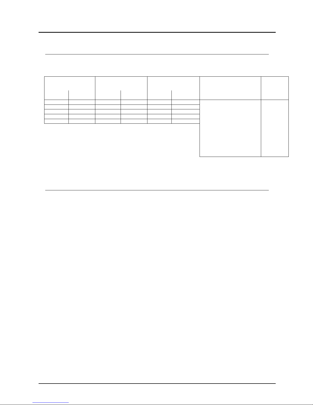
10. Order Codes
(Example: VKP-1020 R25 S)
Standard version
For viscous media For soiled media
(particle size max. 400 m)
Connection Contacts
(not for
VKP-3..)
l/min H2O Order no. l/min. Oil Order no. l/min H2O Order no.
2-20
VKP-1020...
1-18
VKP-2018...
7.5-32.5
VKP-3032...
..R25.. = G 1 AG (standard)
..N25.. = 1 NPT AG
..L18.. = Sold. connection 18 mm
..L22.. = Sold. connection 22 mm
..PVC.. =PVC - glue - in c. 20 mm
..IG1.. = G 1/2 IG, brass
..IG2.. = G 1/2 IG, st. steel
..AG1.. = G 1/2 AG, brass
..AG2.. = G 1/2 AG, st- steel
..AG3.. = G 3/4 AG, brass
..AG4.. = G 3/4 AG, st. steel
0 = without
S = N/O
C = N/C
5-35
VKP-1035...
2-30
VKP-2030...
10-45
VKP-3045...
5-50
VKP-1050...
5-45
VKP-2045...
15-70
VKP-3070...
10-80
VKP-1080...
10-75
VKP-2075...
20-200
VKP-3100...
20-100
VKP-1100...
-
-
-
-
11. Maintenance
In case the medium to be measured is free from contamination, VKP devices are
almost maintenance-free. If lime or dirt deposits on the housing or inside the interior of device, then device needs to be cleaned on regular basis. By means of a
proper fork-wrench, the device may be withdrawn from the piping. Clean the flow
meter with a suitable cleaning-agent or use ultrasonic bath.
Page 9

VKP
VKP K02/0416 page 9
12. Dimensions
13. Recommended Spare-parts
Only the unit-parts and materials are listed.
Corresponding to the unit-type, parts are available in different sizes.
(while ordering, please mention the unit type).
1.1) Flat seal (NBR)
1.2) Flat seal (FPM)
1.3) Flat seal (Klingerit-Oilit)
2.1) Reed-contact (N.O. function)
2.2) Reed-contact (N.C. function)
3.1) Weld on pipe connection. Ms 18mm
3.2) Weld on pipe connection. Ms 22mm
3.3) PVC glue in connection. DN15
3.4) R½ brass female thread
3.5) R½ st. st. female thread
3.6) R½ brass male thread
3.7) R½ st. st. male thread
3.8) R¾ brass male thread
3.9) R¾ st. st. male thread
Page 10

VKP
page 10 VKP K02/0416
14. EU Declaration of Conformance
We, KOBOLD Messring GmbH, Hofheim-Ts, Germany, declare under our sole
responsibility that the product:
Plastic Flow Meter and Monitor, Model: VKP
to which this declaration relates is in conformity with the standards noted below:
EN 61010-1:2011
Safety requirements for electrical equipment for measurement, control and laboratory use
EN 60529:2014
Degrees of protection provided by enclosures (IP Code)
Also the following EC guidelines are fulfilled:
2014/35/EU Low Voltage Directive
2011/65/EU RoHS (category 9)
Hofheim, 27. April 2016
H. Peters M. Wenzel
General Manager Proxy Holder
 Loading...