

Page 1
KOBOLD VKG FLOWMETER/SWITCH
User Instructions
Manual-VKG_8-16
Page 2

Table of Contents
1.0 General . . . . . . . . . . . . . .. . . . . . . . . . . .. . . . . . . . . . . . . . . . . . . . . 1
2.0 Specifications . . . . . . . . . . .. . . . . . . . . . . .. . . . . . . . . . . . . . . . . . . . . 2
3.0 Principle of Operation . . . .. . . . . . . . . . . .. . . . . . . . . . . . . . . . . . . . . 5
4.0 Installation Instructions. . . .. . . . . . . . . . . .. . . . . . . . . . . . . . . . . . . . . 5
4.1 Mounting . . . . . . . . . . . . .. . . . . . . . . . . .. . . . . . . . . . . . . . . . . . . . . 5
4.2 Adjusting the Set point for Increasing Flow. . . . . . . . . . . . . . . . . . . . 6
4.3 Adjusting the Set point for Decreasing Flow . . . . . . . . . . . . . . . . . . 6
4.4 Contact Protection . . . . . . .. . . . . . . . . . . .. . . . . . . . . . . . . . . . . . . . . 7
5.0 Arrival of Damaged Equipment . . . . . . . .. . . . . . . . . . . . . . . . . . . . . 7
6.0 Need help with your VKG? . . . . . . . . . . . .. . . . . . . . . . . . . . . . . . . . . 7
VKG
List Of Diagrams
Diagram 2.3 Dimensions . . . . . . .. . . . . . . . . . . .. . . . . . . . . . . . . . . . . . . . . 3
Diagram 2.4 Wiring of the Reed Switch . . . . . . .. . . . . . . . . . . . . . . . . . . . . 4
Diagram 2.6 Contact Protection . .. . . . . . . . . . . .. . . . . . . . . . . . . . . . . . . . . 7
List of Tables
Table 2.1 Material Composition. . . . . . . . . . .. . . . . . . . . . . . . . . . . . . . . 2
Table 2.2 Operational Limits . .. . . . . . . . . . . .. . . . . . . . . . . . . . . . . . . . . 2
Table 2.5 Electrical Data and Operational Limits. . . . . . . . . . . . . . . . . . 4
PDF Rev. 8/16
Page 3

1VKG
KOBOLD VKG FLOWMETER
User Instructions
CAUTION: For safety reasons, please read the cautionary information located at
the end of the manual, before attempting installation.
1.0 __General
The KOBOLD VKG is a viscosity compensated flowmeter intended for use in
applications where changing viscosities of the measured media make flow determination
difficult.
The VKG offers viscosity independent behavior for fluids in the range of 1-540 cSt (full
compensation). Ordinary float-type flow meters experience measurement errors of up to
1000% with this type of a viscosity change in the medium.
At a glance, the special features of the VKG are:
• Viscosity compensated for ∆v = 540 cSt (mm²/s) enabling use of same scale - no
need for recalibration.
• Density compensated for ∆p = 0.5 kg/l, enabling use of same scale - no recalibration
needed.
• Can be installed in any position.
• Can accurately measure flow of a wide range of media without recalibration.
• Compact.
• A large number of flow set points available (3 reed contacts and/or 5 electronic
contacts).
• Hermetic separation between media and indicator/ electronics.
• Suitable for dark and turgid liquids (with side indicator).
• Easy installation.
• Reliable.
PDF Rev. 8/16
Page 4
VKG 2
2.0 __ Specifications
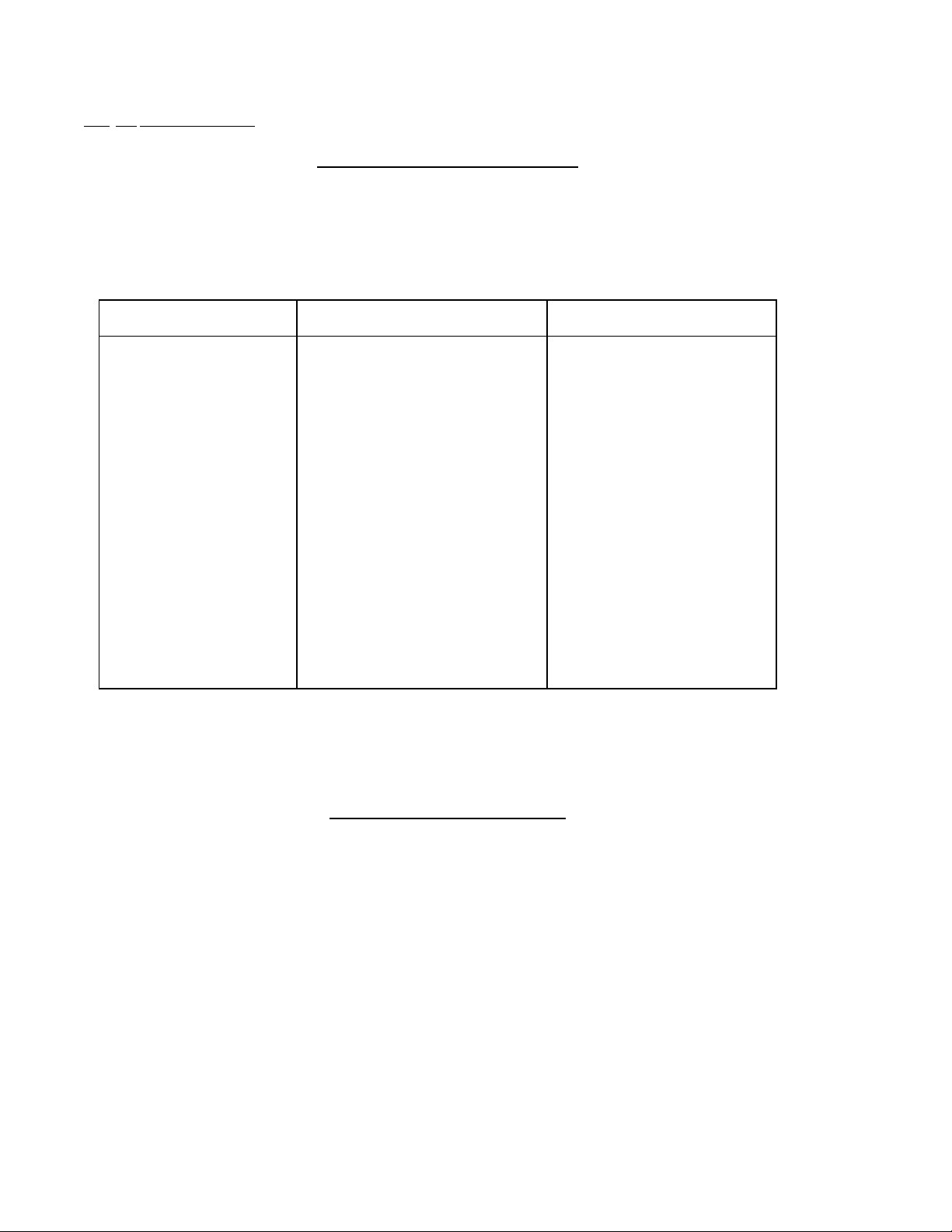
Table 2.1; Material Composition
Material: Brass Material: Stainless Steel
Outer Castings
Spring
Orifice
Magnet
Connections
Float
Measuring Tube
O-ri ngs NBR FKM
A lum inum, ano di ze d
301 Stainless Steel
301 Stainless Steel / Brass
Ceramic oxide
Brass
Brass
Borosilica te Glass
Aluminum, anodized
301 Stainless Steel
301 Stainless Steel
Ceramic oxide
304 Stainless Steel
304 Stainless Steel
Borosilicate Glass
Viscosity Range:
Maximum Medium Temperature:
Maximum Internal Pressure:
PDF Rev. 8/16
Table 2.2; Operational Limits
v = 1 - 540 cSt (mm²/s)
212° F
175 PSIG
Page 5
3VKG
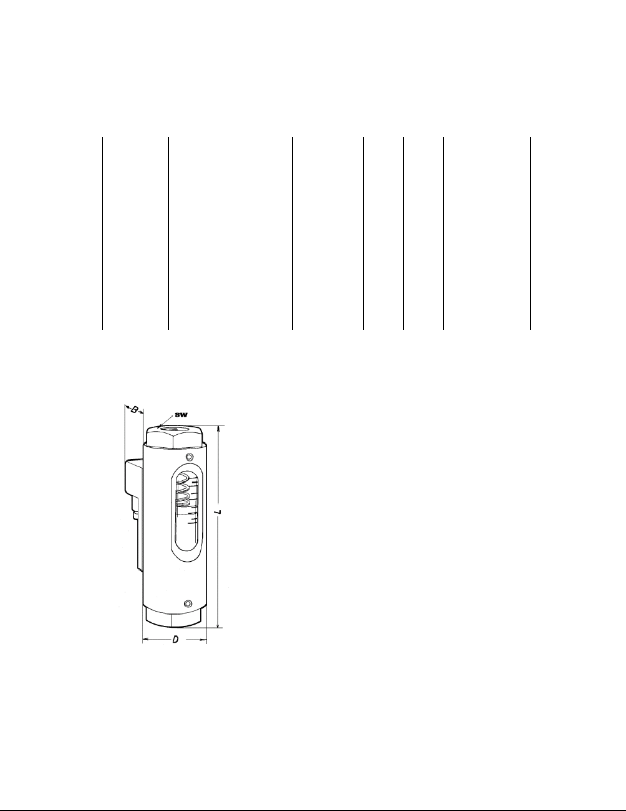
Diagram 2.3; Dimensions
HEX ( mm) NPT L (in) B (in) D (in) Weight (lb)
VKG-..01
VKG-..02
VKG-..03
VKG-..04
VKG-..05
VKG-..06
VKG-..07
VKG-..08
VKG-..09
VKG-..10
VKG-..11
41
41
41
41
41
41
41
41
41
41
41
1/4
1/4 (1/2)*
1/4 (1/2)*
1/4 (1/2)*
1/4 (1/2)*
1/2 (3/4)*
1/2 (3/4)*
3/4 (1)*
3/4 (1)*
3/4 (1)*
1
5.63
5.63
5.63
5.63
5.63
5.63 (6.02)*
5.63 (6.02)*
6.02
6.02
6.02
6.02
2.09
2.09
2.09
2.09
2.09
2.09
2.09
2.09
2.09
2.09
2.09
1.89
1.89
1.89
1.89
1.89
1.89
1.89
1.89
1.89
1.89
1.89
1.55
1.55 (1.77)**
1.55 (1.77)**
1.55 (1.77)**
1.55 (1.77)**
1.77
1.77
1.77 (2.0)**
1.77 (2.0)**
1.77 (2.0)**
2.0
* Larger fitting size listed in parenthesis is optional.
** Weight in parenthesis is for the VKG series with
optional larger fitting size.
PDF Rev. 8/16
Page 6

VKG 4
Diagram 2.4; Wiring of Reed Switch
N/O Contact SPDT Contact
Table 2.5; Electrical Data and Operational Limits
Reed Contact:
Electrical Connection
Standard:
Optional:
Environmental Protection:
Standard: N/O, Optional: SPDT
max. 230 VDC/0.26 A/60 W
60 VDC/1 A/60 W
max. 240 VAC/0.42 A/100 W
100 VAC/1 A/100 W
cCSAus Approved
DIN 43 650 w/Cable Gland
DIN 43 650 w/1/2" NPT Conduit
IP65 (Electrical Switch)
PDF Rev. 8/16
Page 7

5VKG
3.0 __Principle of Operation
The KOBOLD VKG flowmeter has a spring-loaded float which slides within a cylindrical
measuring tube. Our patented process for achieving viscosity compensation hinges on
the use of the nonlinear behavior of the float spring in combination with a unique orifice
integral to the float itself. A large amount of medium density compensation is provided
simultaneously.
Should flow monitoring be desired, limit switches may be added to the device easily.
Permanent magnets on the float actuate an electrically isolated, sealed contact (reed
switch) mounted on the outside of the instrument housing. This arrangement guarantees
hermetic separation of the medium and the electrical system. The contact is embedded
within a plastic housing to prevent damage to the contacts by mechanical action or
aggressive atmospheres. The contact housing is mounted in slides to enable set point
changes to be effected.
The flowing media raises the float against the spring force. When the magnetic field
reaches the contact reeds of the reed switch, the contact actuates. As the flow increases,
the float rises until it reaches its stop. This prevents the float from going beyond the
contact range of the magnetic switch, i.e., the contact remains activated. The result is
bistable switching without a latching relay as normally required.
The magnetic field may be used to couple to an external (i.e., hermetically separated)
indicator. This configuration provides clear indication, even with dark media.
The magnetic field and the indicator are so designed that response to sudden surges in
flow is almost immediate.
4.0 __Installation Instructions
CAUTION: For safety reasons, please read the cautionary information located at
the end of the manual, before attempting installation.
4.1 - Mounting
1. The VKG may be mounted in any orientation without effecting accuracy.
2. The medium must flow through the instrument from inlet to outlet. Note that
reverse flow or backflow can damage the device, thus a check valve is
recommended where this condition may occur. The inlet fitting can be
identified as the fitting where the float rests in a no flow condition.
3. The medium must not contain any solids or contaminants prone to precipitate
out of solution and deposition on the instrument's inner walls, which would
prevent proper operation of the device. Unclean media should be filtered
upstream of the VKG. KOBOLD offers a magnetic/screen filter for such
PDF Rev. 8/16
Page 8

VKG 6
purposes (Type MFR).
4. Do not install the meter on large masses of ferritic materials or in areas where
strong electric fields are present, as this will hamper proper operation of the
reed contact.
5. The media flow rate is referenced at the top edge of the float where it contacts the spring.
- Adjusting the Set point for Increasing Flow
4.2
The set point may be adjusted as follows:
1. Loos
2. Slide the contact upwards along its rail until it reaches its stops.
3. Open the media feed line and set flow to desired volume.
4. Slide the reed contact downwards until the contact actuates.
5. Tighten the hold-down screws.
4.3
- Adjusting the Set point for Decreasing Flow
Adjust the set point as follows:
1. Loosen the hold-down screws on the reed contact housing.
2. Slide the contact downwards (toward inlet) along the rail until it reaches its
3. Open the feed line and introduce flow until the reed contact de-actuates, then
en the hold-down screws on the reed contact housing.
stops. The reed contact will be actuated at this point.
lower the flow value to the desired minimum.
4. Slide the contact upwards (toward outlet) until the reed contact actuates again.
5. Tighten the hold-screws.
PDF Rev. 8/16
Page 9

7VKG
4.4 - Contact Protection
Maximum values of current and voltage must not be exceeded with the reed switch.
When driving inductive or capacitive loads, we recommend protecting the contact as
diagrammed below. If continuous load values exceed contact rating, we recommend the
use of an isolation relay. KOBOLD provides a line of relays for such instances.
Diagram 2.6; Contact Protection
5.0 __Arrival of Damaged Equipment
Your instrument was inspected prior to shipment and found to be defect-free. If damage
is visible on the unit, we advise that you carefully inspect the packing in which it was
delivered. If damage is visible, notify your local carrier at once, since the carrier is liable
for a replacement under these circumstances. If your claim is refused, please contact
KOBOLD Instruments for further advisement.
6.0 __Need help with your VKG?
Call one of our friendly engineers at 412-788-2830.
PDF Rev. 8/16
Page 10

Page 11

9VKG
Caution
PLEASE READ THE FOLLOWING GENERAL FLOW METER/ MONITOR
WARNINGS BEFORE ATTEMPTING INSTALLATION OF YOUR NEW
DEVICE. FAILURE TO HEED THE INFORMATION HEREIN MAY
RESULT IN EQUIPMENT FAILURE AND POSSIBLE SUBSEQUENT
PERSONAL INJURY.
PDF Rev. 8/16
Page 12

Page 13

11 VKG
• KOBOLD manufactures a wide range of process sensors and technologies. While
each of these technologies are designed to operate in a wide variety of applications, it
is the user's responsibility to select a technology that is appropriate for the
application, to install it properly, to perform tests of the installed system, and to
maintain all components. The failure to do so could result in property damage or
serious injury.
• Inspect instrument for damage upon arrival. Cracked, fractured, bent or otherwise
damaged instruments must not be put into use, since the device is weakened to an
unknown extent. (The operations and installation guide will explain how to make a
claim on damaged instruments.)
• Make sure that the model which you have selected is chemically compatible with the
application liquids. While the meter is liquid and spray resistant when installed
properly, it is not designed to be immersed.
• Under NO circumstances must the maximum tolerances (temperature and pressure)
be exceeded.
• The maximum tolerances of the device have been determined using water, air and/or
oil. If using other media, especially corrosive ones, it is critically important that the
user determine chemical compatibility with our instruments. A list, detailing material
composition of our instruments, is available from KOBOLD Instruments Inc. upon
request. KOBOLD Instruments Inc. cannot accept responsibility for failure and
consequences resulting from use of media other than water, mineral oil, air, and
nitrogen.
• Install the device in a fully supported position within your flow system. This avoids
excessive stresses which may damage the instrument. In particular:
a. Ensure that the plumbing leading to and from the instrument is fully supported
and that the instrument does not perform the physical function of a joint.
b. When calculating stress on the device caused by plumbing, the weight of the
medium in the pipes must be considered as well.
c. Misaligned runs of rigid piping can cause large stresses when connected to
the instrument. Do not connect in such a fashion.
• During installation, avoid stresses on the instrument by following guidelines given
below:
a. When connecting fittings, hold the instrument fittings rigid with a correctly
sized wrench. Do not install by twisting the instrument into the pipe fittings.
b. Do NOT install by holding the device housing to provide counter-torque to the
pipe fitting.
PDF Rev. 8/16
Page 14

VKG 12
Use an appropriate amount of PTFE tape on male threads of fitting. This
c.
reduces the twisting stresses produced by tightening the fittings into each
other.
d. Do not use pliers or wrenches on the housing, as this may damage it.
e. Do not overtighten, as this may fracture the fittings.
• During operation there are a number of situations to avoid:
a. The sudden cessation of fluid flow causes what is typically referred to as
“water hammer”. Most people are familiar with this phenomenon from their
home experience - it is the cause behind the loud clank of water pipes which
occurs when faucets are turned off too suddenly. The cause behind this “water
hammer” is quite easy to visualize. Water is fairly massive. The amount of
water in long runs of pipe is quite substantial. When the faucets are turned off
suddenly, especially from a full on condition, the water has considerable
momentum and does not want to stop flowing. The situation is similar to
stopping a car by running into a wall, rather than by applying brakes. Both are
sudden rather than gradual. The damage to the wall can be substantial (not to
mention the car). The “water hammer” causes surges in fluid pressure which
could cause the measurement instrument's pressure limit to be exceeded,
resulting in failure and possible personal injury.
b. Fluid surges, as well as the water hammer, can be particularly damaging to
empty flowmeters since there is no back pressure in the device. The damage
is caused, once again, by momentary excess pressure. To avoid these surges,
fluid lines should remain full (if possible) and water flow should be introduced
to the device slowly.
c. If the instrument is isolated with inlet and outlet valves, the flowmeter must be
completely drained when said valves are both closed. Failure to do so could
result in damage to the device caused by thermal expansion of fluid.
d. Freezing of water in the instrument must be avoided since the resultant
expansion will damage the flowmeter and make it unsafe for use.
e. Design a fail-safe system that accommodates the possibility of switch or
power failure. In critical applications, KOBOLD recommends the use of
redundant backup systems and alarms in addition to the primary system.
PDF Rev. 8/16
 Loading...