

Page 1
Operating instructions for
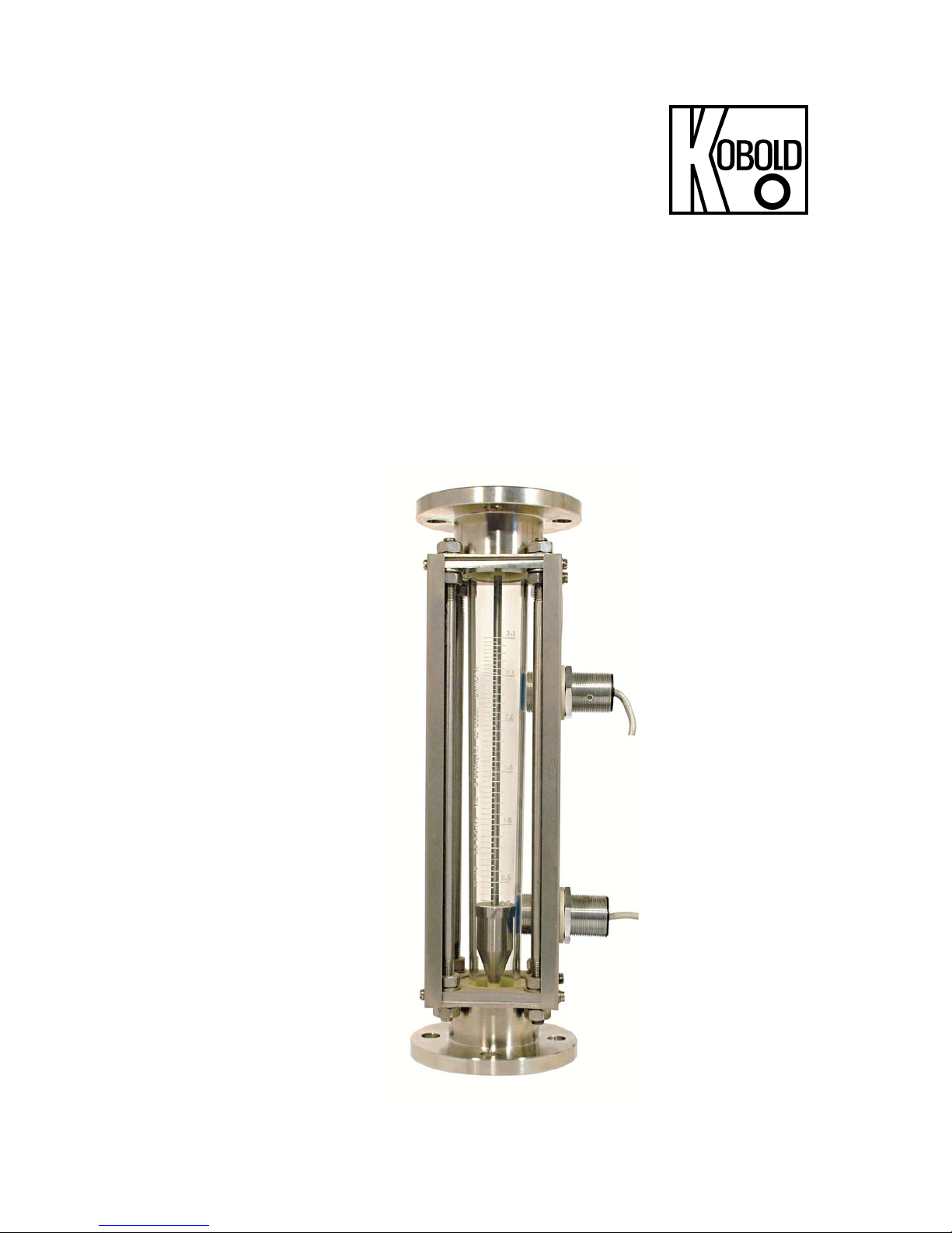
Variable area flow meter
Model URK
Page 2

URK
page 2 URK K03/0817
1. Contents
1. Contents ................................................................................................................... 2
2. Note ......................................................................................................................... 3
3. Instrument inspection ............................................................................................... 3
4. Regulation use ......................................................................................................... 3
5. Operating principle ................................................................................................... 3
6. Mechanical connection ............................................................................................ 4
7. Electrical connection ................................................................................................ 4
7.1. Inductive switch (option) ................................................................................ 4
8. Operation ................................................................................................................. 4
9. Maintenance ............................................................................................................ 5
10. Technical information ............................................................................................... 5
11. Order codes ............................................................................................................. 6
12. Dimensions .............................................................................................................. 7
13. EU Declaration of conformance ............................................................................... 8
Manufactured by
: Sold by:
Kobold-Unirota Ltd. Kobold Messring GmbH
4400 Nyíregyháza Nordring 22-24
Derkovits út 132-136. D-65719 Hofheim
Tel.: +36-42-342-215 Tel.: +49(0)6192-2990
Fax: +36-42-500-175 Fax: +49(0)6192-23398
E-Mail: info.hu@kobold.com E-Mail: info.de@kobold.com
Internet: www.unirota.hu Internet: www.kobold.com
Page 3
URK
URK K03/0817 page 3
2. Note
Please read these operating instructions before unpacking and putting the unit into operation.
Follow the instructions precisely as described herein. The devices are only to be used,
maintained and serviced by persons familiar with these operating instructions and in accordance
with local regulations applying to Health & Safety and prevention of accidents.
When used in machines, the measuring unit should be used only when the machines fulfil the
EC-machine guidelines.
as per PED 2014/68/EU
In acc. with Article 4 Paragraph (3), "Sound Engineering Practice", of the PED 2014/68/EU no CE
mark.
pipeline
filled with
gas liquids
group 2 group 1 group 2
table 7 table 8 table 9
3. Instrument inspection
Instruments are inspected before shipping and sent out in perfect condition. Should damage to a
device be visible, we recommend a thorough inspection of the delivery packaging. In case of
damage, please inform your parcel service / forwarding agent immediately, since they are
responsible for damages during transit.
Scope of delivery:
The standard delivery includes:
• Variable area flow meter: URK
• Operating instructions
• Inductive switch (option)
4. Regulation use
Any use of the variable area flow meter, model: URK, which exceeds the manufacturers
specification, may invalidate its warranty. Therefore any resulting damage is not the
responsibility of the manufacturer. The user assumes all risk for such usage.
Page 4

URK
page 4 URK K03/0817
5. Operating principle
The Kobold URK model flowmeter/monitor works on the basis of the suspended float principle. It
is used for measuring the flow rates in closed pipe line systems.
The medium flows from below through a glass measuring cone that gets wider on top. Thus, the
float is raised and indicates the respective flow rate on the scale provided on the measuring
cone. To monitor flow rate limits, the URK meters can be optionally furnished with “open
collector“ proximity switches.
By its special design, this model is particularly suitable for applications where only very
small operating pressures are available. Another advantage is offered by the very large
sight glass which optically allows direct flow observation.
6. Mechanical connection
Before Installation:
• Remove all transportation safety locks and ensure that no packing material remains within
the unit.
• Be sure that the maximum allowable operating pressure and temperature is not exceeded
(see Technical data).
• Install the by-pass level indicator at the side of the round containers, ensure the instrument
is under no mechanical stress/tension (install support bracing if necessary).
• Protect the measuring tube from external damage.
• Avoid pressure peaks in the measuring tube, e.g. from sudden surges or stoppage of flow.
• If possible, immediately after making mechanical connections, check whether the
connections are properly sealed with no evidence of leakage.
• Make sure that the connections are in plain.
7. Electrical connection
7.1. Inductive switch (option)
• Make sure that the supply wires are de-energized.
Page 5

URK
URK K03/0817 page 5
8. Operation
In order to initialise the inductive switch function, it is essential that the float activates the contact
once in each direction.
Adjustment of limit-values
The switch-point can be adjusted to the desired levels by using.
Reference edge: approx. the middle of the sensor.
Slide the switch housing up or down until the reference edge coincides with the desired
switch-point scale reading.
Overranging
With non-pulsating flow, the maximum flow rate can be exceeded. Only an increase in pressure
loss will result (max. permissible operating pressure must not be exceeded!)
9. Maintenance
If the medium to be measured is clean, the series URL is virtually maintenance- free. If deposits
form on the inner housing or parts, periodic cleaning of the unit is recommended. Remove the
units from the piping with a suitable tool; clean the flow meter with a suitable cleaning agent or
make use of an ultrasonic bath.
10. Technical information
Installation position: vertical (flow from bottom to top)
Accuracy class: 4 according to VDI
Max. temperature: 100°C (65°C for PVC)
Max. pressure: 03H…23H; 16 bar (with PN 16 flange)
25H…33H; 12 bar (with PN 16 flange)
35H…41H; 8 bar (with PN 16 flange)
01L…23L; 16 bar (with PN 16 flange)
25L…33L; 10 bar (with PN 16 flange)
in all other cases 6 bar
Calibration conditions:
water: 20°C, air: 20°C,
air pressure: 1.013 bar abs.
Contact (optional): proximity switch: PNP
open collector, n/o contact
Supply voltage: 12…24 VDC
Current consumption: max. 10 mA
Cable: 2 m, PVC-insulated
Ambient temperature: -25…+70°C
Protective category: IP 67
Page 6

URK
page 6 URK K03/0817
11. Order codes
Model
Material
combi-
nation
Measuring range
Pressure
loss
[mbar]
Flange
Contacts
water [L/h] air [m³N/h]
DIN 2526.
Form C. PN 6
DIN 2526.
Form C. PN 16
ANSI
150 lbs
URK-
73
33
55
99**
01L = 0.02…0.2
10
F4 = DN 15
F5 = DN 20
B4 = DN 15
A4 =½"
A5 = ¾"
0 = no
contact
P* = 1 PNP
normally open
R* = 2 PNP
normally open
03H = 1…10
03L = 0.032…0.32
10
05H = 1.6…16
05L = 0.05…0.5
10
07H = 2.5…25
07L = 0.08…0.8
12
09H = 4.0…40
09L = 0.13…1.3
9
11H = 6.3…63
11L = 0.2…2.0
17
13H = 10…100
13L = 0.32…3.2
24
15H = 16…160
15L = 0.5…5
28
F6 = DN 25
B5 = DN 20
B6 = DN 25
A6 = 1"
A7 = 1 ¼"
17H = 25…250
17L = 0.8…8
28
19H = 40…400
19L = 1.3…13
36
21H = 63…630
21L = 2.0…20
34
23H = 100…1 000 23L = 3.2…32
43
25H = 160…1 600 25L = 5…50
48
F7 = DN 32 B7 = DN 32
A8 = 1 ½"
27H = 250…2 500 27L = 8…80
48
29H = 400…4 000 29L = 13…130
51
F8 = DN 40 B8 = DN 40
A9 = 2"
31H = 630…6 300 31L = 20…200
57
33H = 1 000…10000
33L
***
= 25…250 70 F9 = DN 50
B9
= DN 50
35H = 1 600…16000
35L
***
= 32…320 93
FA = DN 65 BA
= DN 65
AA =
2 ½"
AB = 3"
37H = 2 500…25000
37L
***
= 40…400 102
39H = 10 000…40 000 39L
***
= 50…500 95
FB = DN 80 BB
= DN 80 –
41H = 15 000…50 000
102
*Other switching functions on request
**Customer specification on request
*** 33L; 35L; 37L and 39L air ranges only available with aluminum or PTFE float
Page 7

URK
URK K03/0817 page 7
12. Dimensions
Model H [mm]
DIN ANSI
DN
PN6PN16
Size
Class 150 RF
D1 [mm] D
2
[mm]
D
1
[mm]
D
2
[mm]
D1 [mm] D
2
[mm]
URK-..4x 380 15
80 55 95 65 ½" 88.9 60.5
URK-..5x
390
20
90 65 105 75 ¾" 98.6 69.9
URK-..6x
390
25
100 75 115 85 1" 108.0 79.2
URK-..7x
400
32
120 90 140 100 1¼" 117.3 88.9
URK-..8x 410 40
130 100 150 110 1½" 127.0 98.6
URK-..9x
410
50
140 110 165 125 2" 152.0 120.7
URK-..Ax
550
65
160 130 185 145 2½" 177.8 139.7
URK-..Bx
560
80
190 150 200 160 3" 190.5 152.4
Material combination URK
Ordering
code Connection Float Seal Ring Housing Sight glass
Measuring
cone
73 cast iron 1.4301 NBR PVC
st.st.
1.4301
plexiglass
borosilicate
glass
33 1.4301 1.4301 FPM PTFE
55 1.4404 1.4404 FPM PTFE
99** cast iron
1.4301
1.4404
1.4301
1.4404
aluminium
PTFE
PVC
PP
NBR
EPDM
FPM
PTFE
PVC
PTFE
1.4301
** Customer specification on request
Page 8

URK
page 8 URK K03/0817
13. Declaration of conformance
We, KOBOLD Messring GmbH, Hofheim-Ts, Germany, declare under our sole
responsibility that the product:
Variable area flow meter Model: URK
to which this declaration relates is in conformity with the standards noted below:
EN 61000-6-2:2006 Immunity industrial environment
EN 61000-6-3:2011 Emission residential, commercial
EN 55011:2009+A1:2010 ISM ratio-frequency equipment
EN 61326-1:2013 Electrical equipment for measurement, control and
laboratory use – EMC requirements
EN 61010-1:2011 Safety requirements for electrical measuring, control and
laboratory devices
Also the following EC guidelines are fulfilled:
2014/30/EU EMC Directive
2011/65/EU RoHS (category 9)
EN 50581:2012 Technical documentation for the assessment of electrical and
electronic products with respect to the restriction of hazardous substances
Hofheim, 16. August 2017
H. Peters M. Wenzel
General Manager Proxy Holder
 Loading...