

Page 1
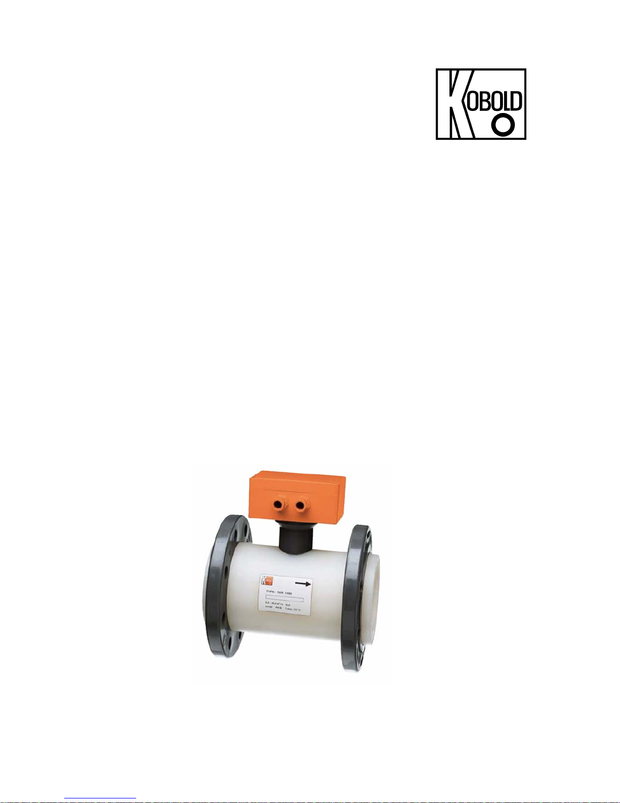
Operating Instructions
for
Turbine Wheel Flow Meter
Model: TUR
Page 2

TUR
page 2 TUR K02/0618
1. Contents
1.
Contents ........................................................................................................ 2
2. Note .............................................................................................................. 3
3. Instrument Inspection .................................................................................... 3
4. Regulation Use .............................................................................................. 4
5. Operating Principle ........................................................................................ 4
6. Mechanical Connection ................................................................................. 5
7. Electrical Connection .................................................................................... 6
8. Electrical Commissioning .............................................................................. 7
8.1. ADI-Evaluating Electronics .................................................................. 7
9. Mechanical Commissioning........................................................................... 8
10.Maintenance ................................................................................................. 8
11.Technical Information .................................................................................... 9
12.Order Codes ............................................................................................... 10
13.Materials ..................................................................................................... 11
14.Dimensions ................................................................................................. 12
15.Pressure Loss Diagram ............................................................................... 14
16.EU Declaration of Conformance .................................................................. 15
Manufactured and sold by:
Kobold Messring GmbH
Nordring 22-24
D-65719 Hofheim
Tel.: +49(0)6192-2990
Fax: +49(0)6192-23398
E-Mail: info.de@kobold.com
Internet: www.kobold.com
Page 3

TUR
TUR K02/0618 page 3
2. Note
Please read these operating instructions before unpacking and putting the unit
into operation. Follow the instructions precisely as described herein.
The devices are only to be used, maintained and serviced by persons familiar
with these operating instructions and in accordance with local regulations applying to Health & Safety and prevention of accidents.
When used in machines, the measuring unit should be used only when the
machines fulfil the EC-machine guidelines.
as per PED 2014/68/EU
In acc. with Article 4 Paragraph (3), "Sound Engineering Practice", of the
PED 2014/68/EU no CE mark.
Diagram 8, Pipe, Group 1 dangerous fluids
3. Instrument Inspection
Instruments are inspected before shipping and sent out in perfect condition.
Should damage to a device be visible, we recommend a thorough inspection of
the delivery packaging. In case of damage, please inform your parcel service /
forwarding agent immediately, as they are responsible for damages during transit.
Scope of delivery:
The standard delivery includes:
Turbine Wheel Flow Meter, model: TUR
Operating Instructions
Page 4

TUR
page 4 TUR K02/0618
4. Regulation Use
The TUR series units are used for the flow measurement of liquids. These units
are furnished with the following outputs.
Pulse Output
Rotary motion of the turbine a signal with a specific frequency.
Analogue Output
In order to transduce the measured flow data, an analogue output is available,
(DIN IEC 381) with 0-20 mA, 4-20 mA or 0-10 V (see Type-tag).
Only low-viscosity media flows that are chemically compatible with the sensor
housing materials may be measured. With higher-viscosity media, considerable
measurement-errors will occur.
Long fibre-pieces may jam the rotor.
5. Operating Principle
The unit comprises a thick-walled plastic pipe; rotatable PVC flanges are secured
at each end.
At the meter inlet and outlet bearing supports help to reduce media turbulence. A
turbine-wheel with a core of moulded soft iron rotates as the liquid flows trough
the body.
The metallic parts are not exposed to the medium and are therefore protected
against corrosion. The bearings are made of sapphire and are self adjusting.
The bearings are made of chemically highly resistant Wolfram-carbide and are
moulded into the turbine wheel. The rotation is sensed through the built in pulse
transmitter, which requires no sealing and has now mechanical connection with
the turbine wheel. This rotation is converted into pulses by the associated
electronics.
The version with integrated transducer converts the frequency into a standardanalogue signal. An optionally available, external electronic unit processes the
pulse output-signal to drive a display, allows limit contact produces an analogue
output or indicate the measure of flowing volume.
Page 5

TUR
TUR K02/0618 page 5
6. Mechanical Connection
Before Installation:
Please ensure that the actual flow-rate corresponds with the measured volume
within measuring range of the unit. Measuring range is printed on the type-tag.
Attention! Exceeding the measuring range (more than 20 %) may
result in damage to bearings and considerable measurementerrors.
Make sure that the permitted max. pressure and temperature are not
exceeded during unit operation.
Please ensure that the power supply of the unit corresponds with the power
requirements (operational data) printed on the Type-tag.
Ensure that no packing material remains inside the unit.
Mounting of these units is position-independent; the flow must always follow
the direction of arrow.
During installation, please ensure that the pipe inlet straight is 4 times and
outlet straight is 2 times of nominal diameter of the unit.
The installation is potential-free, and should be carried out with the help of soft
sealing rings or gaskets (not in the scope of delivery).
If possible, just after mechanical installation, it should be checked that the
flange-connections are properly sealed.
Page 6

TUR
page 6 TUR K02/0618
7. Electrical Connection
Warning! Please ensure that the supply voltage to your instrument
conforms to the value given on the equipment label.
Ensure that the power lines are not active.
With units without transducer, connect the
cable-ends with your power supply and
load, as is shown in the figure.
Units with transducer require cable
connections through PG connector. Make
the connections according to figure 2.
Power supply cable: area of cross-section
should be min. 0.75 mm².
Warning! Incorrect wiring in the coupling plug can lead to damage to
the electronics.
Page 7

TUR
TUR K02/0618 page 7
8. Electrical Commissioning
The instrument is delivered ready to operate.
On Instruments with transducers the electronic is matched and calibrated with
the transducer. Calibration screws are not intended for customer's use. An
attempt to calibrate the unit by the customer would require a new calibration to
restore factory accuracy (rendered by the firm, on payment).
8.1. ADI-Evaluating Electronics
See completion to operating instructions for ADI-Evaluating Electronics
Page 8

TUR
page 8 TUR K02/0618
9. Mechanical Commissioning
To avoid pressure shocks, the flow medium should run slowly into the unit.
Warning! Pressure shocks from solenoid valves, ball valves or
similar devices may lead to breakage of the instrument (water
hammer). In the operating condition, it must be checked that the
instrument housing is continuously filled with the flow medium.
Attention! Large air bubbles in the measuring chamber may lead
to measurement errors as well as destruction of the bearings.
10. Maintenance
In case that the medium (to be measured) is not polluted, the model TUR is
maintenance-free.
Should the cleaning of unit becomes necessary, it is easier to do by loosening the
three plastic screws on one side and then the turbine may be taken out and
cleaned.
During installation of the turbine wheel and bearing support, please observe that
the Sapphire bearing is pushed straight onto the axle. The bearing support slides
into the measuring pipe without applying any force and is secured in position with
the help of screws.
Warning! Damage rendered to sapphire bearings caused by careless
handling and assembling expires the guarantee.
Restoration work on electronic part may only be conducted by the supplier in
order to ascertain the validity of guarantee.
Page 9

TUR
TUR K02/0618 page 9
11. T echnical Information
Measuring accuracy: ±1% of f. s.
Viscosity range: for low-viscosity media
Max. operating temperature: 60 °C (PVC version)
70 °C (PVDF version)
Max. operating pressure: PN 10
Protection type: IP 65
PVC version PVDF version
(1) Fitting PVC PVDF
(2) Bearing cross bars PVC PVDF
(3) Turbine wheel PVC PVDF
(4a) Bearing bush sapphire sapphire
(4b) Bearing axle sapphire sapphire
(6) Bolts polyamide PVDF
(7) Flange PVC PVC
Frequency output
Power supply: 24 VDC ±20%
Idle current: typ. 15 mA
Pulse output: PNP or NPN, max. 400mA
Electrical connection: 2 m PVC cable
Transmitter
Power supply: 230 VAC, 24 VAC, 24 VDC
Output: 0-20 mA, 4-20 mA or 0-10 VDC, 4-wire
Max. load: 500
Electrical connection: adapter box with cable connection
Compact electronics
Display: 3-segment LED
Analogue output: (0)4 -20 mA adjustable, max. 500 Ω
Switching outputs: 1 (2) semiconductor PNP or NPN, factory set
Contact operation: N/C/N/O contact programmable
Setting: with 2 buttons
Power supply: 24 VDC ±20%, 3-wire technology
Electrical connection: plug connector M12x1
Page 10

TUR
page 10 TUR K02/0618
ADI electronics
Display: bar graph and 5 digit digital display
Analogue output: (0)4-20 mA, 0-10 VDC
2 switching outputs: relay/changeover contact
max. 250 VAC/5 A
resistive load max. 30 VDC/5 A
Setting: via 4 buttons
Power supply: 100...240 V
AC
± 10% or
18...30 V
AC
/10...40 VDC
Electrical connection: pluggable terminal block via cable gland
12. Order Codes
Measuring sensor with frequency output – Order details
(example: TUR-1025 N)
Connection
PVC flange
NW
Measuring
range
m³/h water
Frequency
range
Hz
Frequency
Pulses/Liter
Model designation
wetted parts
Pulse
detector
PVC PVDF
25 0.2 - 5.0 5.5 - 157 113
TUR-1025... TUR-1125...
..N
pulse detector
50 1.2 - 20.0 4.8 - 79.4 14,30
TUR-1050... TUR-1150...
NPN, 24 V
DC
,
3-wire
80 2.0 - 80.0 2.7 - 106.4 4,79
TUR-1080... TUR-1180...
..P
pulse detector
100 2.5 - 100.0 2.1 - 82.2 2,96
TUR-1010... TUR-1110...
PNP, 24 V
DC
,
3-wire
Page 11

TUR
TUR K02/0618 page 11
Measuring sensor with ADI electronics – Order details
(example: TUR-2025 M000)
Connection
PVC flange
Nominal dia.
Measuring
range water
[m³/h]
Model designation
wetted parts
Evaluating electronics
Transmitter
PVC PVDF Supply Output
25 0.2-5.0
TUR-2025... TUR-2125...
..M0.. = 230 V
AC
..M2.. = 24 V
AC
..M3.. = 24 V
DC
..40 = 4-20 mA
..00 = 0-20 mA
..10 = 0-10 V
DC
50 1.2-20.0
TUR-2050… TUR-2150…
Compact electronics*
..C30R=LED-display, 2x open collector, PNP, plug con. M12x1
..C30M = LED-display, 2x open collector, NPN, plug con. M12x1
..C34P = LED-display, 4-20 mA, 1x open coll., PNP, plug con. M12x1
..C34N = LED-display, 4-20 mA, 1x open coll. NPN, plug con. M12x1
Counter electronics
..E34R = 24 V
DC
, 0(4)-20 mA
..E31R = 24 V
DC
, 0-10 V
..E04R = 90-250 V
AC
, 0(4)-20 mA
..E01R = 90-250 V
AC
, 0-10 V
Dosing electronics
..G34R = 24 V
DC
, 0(4)-20 mA
..G31R = 24 V
DC
, 0-10 V
..G04R = 90-250 V
AC
, 0(4)-20 mA
..G01R = 90-250 V
AC
, 0-10 V
ADI-electronics*
80 2.0-80.0
TUR-2080… TUR-2180…
100 2.5-100.0
TUR-2010... TUR-2110...
Display Supply Output Contacts
..K..= Bar graph/
digital display
..0.. = 100-240 V
AC/DC
..3.. = 18-30 V
AC
10-40 VDC
..0..= without
..4..= 0(4)-20 mA
0-10 V
..2= 2 changeover
contacts
13. Materials
PVC version PVDF version
Fitting, Bearing cross bars, Turbine wheel
Bearing bushing, Bearing axle
Bolts
Flange
PVC
Sapphire
Polyamide
PVC
PVDF
Sapphire
PVDF
PVC
*Please specify flow direction in writing
Page 12

TUR
page 12 TUR K02/0618
14. Dimensions
DN b D g H2* H3 K L n l t
25 15 115 58 87 127 85 160 4x 14 9
50 20 165 88 100 140 125 200 4x 18 11
80 22 200 123 115 155 160 225 8x 18 11
100 22 220 145 125 165 180 250 8x 18 11
*with PNP or NPN Sensor
Page 13

TUR
TUR K02/0618 page 13
TUR with compact
Description Dimension A
TUR-..25 112
TUR-..50 125
TUR-..80 140
TUR-..10 150
TUR with ADI-, Gxxx- and Exxx electronics
Description Dimension A
TUR-..25 77
TUR-..50 90
TUR-..80 105
TUR-..10 115
Page 14

TUR
page 14 TUR K02/0618
15. Pressure Loss Diagram
Page 15

TUR
TUR K02/0618 page 15
16. EU Declaration of Conformance
We, KOBOLD Messring GmbH, Hofheim-Ts, Germany, declare under our sole
responsibility that the product:
Turbine Wheel Flow Meter Model: TUR-1
which relates to this certificate, conforms to the standards listed below:
EN 60947-5-2:2007 + A1:2012
Low-voltage switchgear and controlgear - Part 5-2: Control circuit devices and
switching elements - Proximity switches
EN 50581:2012 Technical documentation for the assessment of electrical
and electronic products with respect to the restriction of hazardous substances
Also the following EU guidelines are fulfilled:
2014/30/EU EMC Directive
2011/65/EU RoHS
Hofheim, 14. june 2018
H. Peters M. Wenzel
General Manager Proxy Holder
Page 16

TUR
page 16 TUR K02/0618
We, KOBOLD Messring GmbH, Hofheim-Ts, Germany, declare under our sole
responsibility that the product:
Turbine Wheel flow Meter Model: TUR-2
to which this declaration relates is in conformity with the standards noted below:
EN 61000-6-3:2011
Electromagnetic compatibility (EMC) - Part 6-3: Generic standards - Emission
standard for residential, commercial and light-industrial environments
EN 61000-6-4:2011
Electromagnetic compatibility (EMC) - Part 6-4: Generic standards - Emission
standard for industrial environments
EN 61010-1:2011
Safety requirements for electrical equipment for measurement, control and
laboratory use - Part 1: General requirements
EN 50581:2012
Technical documentation for the assessment of electrical and electronic products
with respect to the restriction of hazardous substances
Also the following EU guidelines are fulfilled:
2014/30/EU EMC Directive
2014/35/EU Low Voltage Directive
2011/65/EU RoHS
Hofheim, 14. june 2018
H. Peters M. Wenzel
General Manager Proxy Holder
 Loading...