

Page 1
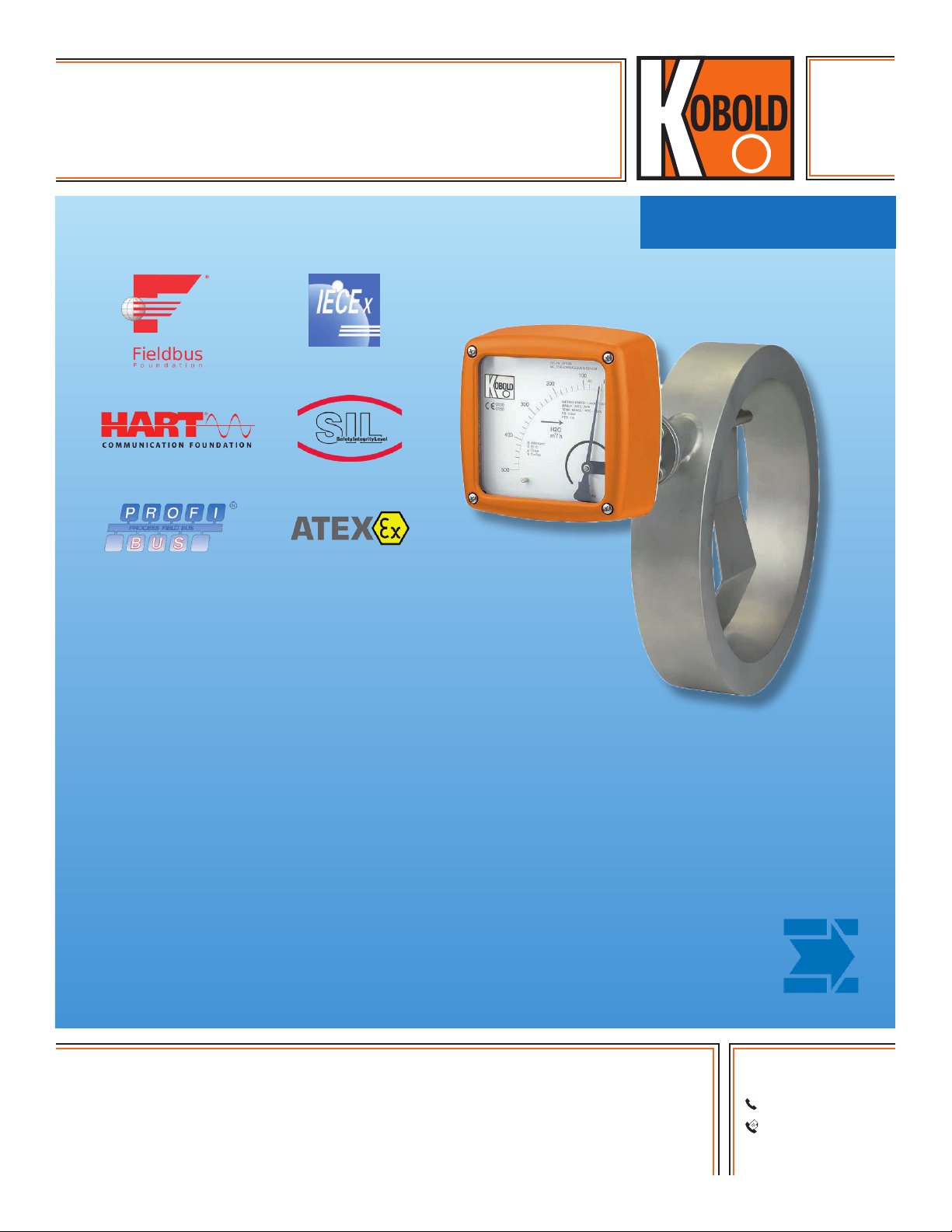
Flap-Type Flowmeter
measuring
•
monitoring
•
analyzing
TSK
• Range: 6.6...26.4 to 880...6600 GPM
• Accuracy: ± 2.5% of Full Scale
• P
• T
: 580 PSI
max
: -40 …572 °F
max
• Connection: Wafer Flange 1.5" …20" ASME
• Material: Stainless Steel, Hastelloy C®, PTFE
• Options: Limit Contacts, Analog Output
with HART® or PROFIBUS-PA® Counter
KOBOLD companies worldwide:
ARGENTINA, AUSTRALIA, AUSTRIA, BELGIUM, BULGARIA, CANADA, CHILE, CHINA, COLOMBIA,
CZECH REPUBLIC, EGYPT, FRANCE, GERMANY, HUNGARY, INDIA, INDONESIA, ITALY, MALAYSIA,
MEXICO, NETHERLANDS, PERU, POLAND, REPUBLIC OF KOREA, ROMANIA, SINGAPORE, SPAIN,
SWITZERLAND, TAIWAN, THAILAND, TUNISIA, TURKEY, UNITED KINGDOM, USA, VIETNAM
05/04-23-2019
KOBOLD Instruments, Inc.
1801 Parkway View Drive
Pittsburgh, PA 15205
Main Ofce:
1.800.998.1020
1.412.788.4890
info@koboldusa.com
www.koboldusa.com
Page 2
Flap Style Flowmeter Model TSK
Description
The KOBOLD TSK measures liquid flow in pipes and can be used in
all directions of flow. It shows the current flow rate in volume or mass
per unit in time. It is designed to handle difficult and adverse operating
conditions. It is available with electronic options for remote process
monitoring and control. The principal of operation is as follows:
If a media flows with sufficient velocity through the horizontally or
vertically mounted TSK fitting, the paddle swivels around the axle
until the force of the media and the opposing force of the paddle
surface plus the spring tension establish equilibrium. The angular
position, or the position of equilibrium of the paddle in the measuring
compartment, is the measure for the flow. The encapsulated ringtype permanent magnet at the end of the paddle axis transmits this
position to the scale and the optional electronic evaluators through
the magnet tracking indicator system. This happens safely and
without packing glands. The flow rates shown on the scale only
apply to the calibrated media or to a media with the same physical
characteristics.
Specifications
Sensor Materials:
TSK-S: 316L SS / 316-Ti SS
TSK-H: Hastelloy C-22® / Hastelloy C-22
TSK-P: PTFE / Hastelloy C-22
®
®
Option: Others on Request, Consult Factory
Process Connection: Wafer Acc. EN 1092,
ASME B16.5, DIN 2512,
Special Connections on Request
Nominal Pressure
TSK-S/H: 580 PSIG ASME Cl150 or 300 (Standard)
TSK-P: 232 PSIG ASME Cl150 (Standard)
Higher Pressure Rates Optional
Process Temperature:
TSK-S/H: -40...572 °F
TSK-P: -4...257 °F
Ambient Temperature: -40...176 °F
Ingress Protection: IP 65 (EN60529)
Accuracy (Liquid): ± 2.5% of Full Scale
± 0.2% with Transmitter (ES)
Repeatability: ± 0.5%
Certification: Explosion Protection:
BVS 03 ATEX H/B 112
CE-Marking: Pressure Equipment
Directive 97/23/EC
Display
Materials: Aluminum (Enameled)
Stainless Steel (Option)
Outputs: Inductive Switch or Microswitch
Ambient Temperature: -40...176 °F (without Switch)
-40...149 °F (with Switch)
Transmitter
ES with HART®-Protocol
ES with HART®-Protocol and 2 NAMUR-Switches
ES with PROFIBUS-PA
®
ES with HART®-Protocol and Counter Module
Power Supply: 14 - 30 V
Output: Passive, Galvanically Isolated
DC
Current: 4-20 mA
Binary 1 and 2: Ui=30 V, I i=20mA, Pi=100 mW
Input Binary: Counter Reset (only for ES with
Counter Module)
Ambient Temperature: -40...158 °F
Ingress Protection: IP 65 (EN60529)
Certification
Explosion Protection: DMT 00 ATEX E 075
Type of Protection: II 2G EEx ia IIC T6
CE-Marking: Explosion Protection Directive
94/9/EC
2
www.koboldusa.com
No responsibility taken for errors;
subject to change without prior notice.
Page 3

Flap Style Flowmeter Model TSK
Order Details (Example: TSK-S 205R B1 U 6 V 00 S 5 0)
Model
Process
Connection
..205R.. = 1-1/2" Class 150
..225R.. = 1-1/2" Class 300
..206R.. = 2" Class 150
..226R.. = 2" Class 300
..207R.. = 2-1/2" Class 150
..227R.. = 2-1/2" Class 300
..208R.. = 3" Class 150
TSK-S.. =
Armature and Built-in
Parts Stainless Steel
..228R.. = 3" Class 300
..210R.. = 4" Class 150
..230R.. = 4" Class 300
..211R.. = 5" Class 150
TSK-H.. =
Armature and Built-in
Parts Hastelloy C-22
..231R.. = 5" Class 300
..212R.. = 6" Class 150
®
..232R.. = 6" Class 300
TSK-P3)..=
Armature PTFE, Built-in
Parts Hastelloy C-22
..213R.. = 8" Class 150
®
..214R.. = 10" Class 150
..215R.. = 12" Class 150
..216R.. = 14" Class 150
..217R.. = 16" Class 150
..219R.. = 20" Class 150
Special Seal Certificate Display Scale ElectricalOutputs
(For protection against
incoming solids, ie;
metal shavings and small
debris, from entering the
transmission chamber.)
..0.. = Without
..0.. = Without
..1.. = FKM, Max 302°F
..2..= FEP, Max 392°F
..1.. = Certificate of Compliance
with the Order 2.1
..2.. = Test Report 2.2
..B.. = Inspection Certificate 3.1
..C.. = Inspection Certificate 3.2
3)
TSK-P max. 257 °F
No responsibility taken for errors;
subject to change without prior notice.
Water Range
(GPM)
..B1.. = 6.6...26.4
..B2.. = 6.6...44
..B3.. = 13.2...66
..C1.. = 6.6...44
..C2.. = 13.2...132
..D1.. = 6.6...61.6
..D2.. = 17.6...132
..D3.. = 26.4...220
..E1.. = 17.6...106
..E2.. = 44...264
..F1.. = 26.4...176
..F2.. = 35.2...352
..G1.. = 44...264
..G2.. = 88...528
..H1.. = 66...440
..H2.. = 132...880
..J1.. = 110...704.5
..J2.. = 220...1211
..J3.. = 264...1760
..K1.. = 220...880
..K2.. = 330...1760
..K3.. = 352...2202
..L1.. = 352...1760
..L2.. = 440...2640
..M1.. = 528...3082
..M2.. = 660...4400
..N1.. = 660...3520
..N2.. = 880...5724
..P1.. = 880...5724
..P2.. = 880...6605
..S.. = Standard
(Aluminum)
..E.. = Stainless
Steel Display
IP 67
..T.. = Standard
(Aluminum)
with Pressure
Compensation
www.koboldusa.com
Flow
Direction
..U.. = From the
Bottom to
the Top
..O.. = From the
Top to the
Bottom
..L.. = From the
Left to the
Right
..R.. = From the
Right to the
Left
..1.. = %-Scale
(Water)
..2.. = Range-Scale
(Water)
..4.. = %-Scale
(Media)
..5.. = Range-Scale
(Media)
..F.. = Dual-Scale
(Media)
Customer
Preference
Temperature Class Seal
..2.. = Max. 572 °F,
Magnet
Encapsulation
Stainless Steel,
Forward
Advanced
Display
..3.. = Max. 392 °F,
Magnet
Encapsulation
Stainless
Steel, Forward
Advanced
Display
..4.. = Max. 275 °F,
Magnet
Encapsulation
PVDF, Forward
Advanced
Display
..5.. = Max. 212 °F,
Magnet
Encapsulation
PVDF
..0 = Without
..1 = 1x Inductive Limit Contact
..2 = 2x Inductive Limit Contacts
..6 = Electr. Transmitter ES,
HART® Protocol, 4-20 mA, EEx ia
..7 = Electr. Transmitter ES,
HART® Protocol, 4-20 mA,
EEx ia, 2x Namur Contacts
..9 = Electr. Transmitter ES,
PROFIBUS-PA®, EEx ia
..C = 1x Microswitch Limit Contact
..D = 2x Microswitch Limit Contacts
..E = 1x PNP Transistor Limit Contact
..F = 2x PNP Transistor Limit Contacts
..I = 4-20 mA w/ HART® and Counter Module
..K = 4-20 mA with Fieldbus Foundation
..V.. = FKM
(Max. 302 °F)
..F.. = FEP
(Max. 392 °F)
..S.. = Stainless Steel
(Max. 572 °F)
3
Page 4

Dimensions
Flap Style Flowmeter Model TSK
Size
(inch)
ASME
Nominal Pressure
(Standard)
Class
Display
Aluminium
L
(inch)
Stainless Steel
D
(inch)
Display
ASME- Flange
2 300 10.71 10.28 3.63 0.67
2-1/2 300 10.71 10.28 4.02 0.83 (ASME = 0.67)
3 300 10.71 10.28 5.00 1.22
4 150 10.71 10.28 6.22 1.42
5 150 13.85 13.43 7.32 1.77
6 150 13.85 13.43 8.35 2.09
8 150 13.85 13.43 10.55 3.15
10 150 13.85 13.43 12.60 3.54
12 150 14.65 14.21 15.00 3.94
14 150 17.40 16.97 16.26 3.94
16 150 17.79 17.36 18.50 5.12
20 150 19.37 18.94 23.03 5.12
Standard Display for Horizontal Flow
Standard Display for Vertical Flow
h
(inch)
5.87"
5.87"
4.29"
4.29"
5.87"
5.87"
2.52"
2.52"
3.58"
3.58"
4.10"
4.10"
5.87"
4.10"
4.29"
5.87"
3.15"
2.52"
2.52"
3.15"
4.29"
5.87"
4.10"
5.87"
4
www.koboldusa.com
No responsibility taken for errors;
subject to change without prior notice.
Page 5

Flap Style Flowmeter Model TSK
Size
(inch)
ASME
Nominal Pressure
(Standard)
Class
Display
Aluminium
L
(inch)
Stainless Steel
D
(inch)
Display
ASME- Flange
2 300 10.71 10.28 3.63 0.67
2-1/2 300 10.71 10.28 4.02 0.83 (ASME = 0.67)
3 300 10.71 10.28 5.00 1.22
4 150 10.71 10.28 6.22 1.42
5 150 13.85 13.43 7.32 1.77
6 150 13.85 13.43 8.35 2.09
8 150 13.85 13.43 10.55 3.15
10 150 13.85 13.43 12.60 3.54
12 150 14.65 14.21 15.00 3.94
14 150 17.40 16.97 16.26 3.94
16 150 17.79 17.36 18.50 5.12
20 150 19.37 18.94 23.03 5.12
Stainless Steel Display for Horizontal Flow
Stainless Steel Display for Vertical Flow
h
(inch)
7.72"
7.72"
1.38"
2.52"
2.52"
1.38"
3.19"
3.19"
5.04"
5.04"
7.72"
1.18"
5.24"
3.19"
2.52"
2.52"
3.19"
1.18"
7.72"
5.24"
No responsibility taken for errors;
subject to change without prior notice.
www.koboldusa.com
5
 Loading...