

Page 1
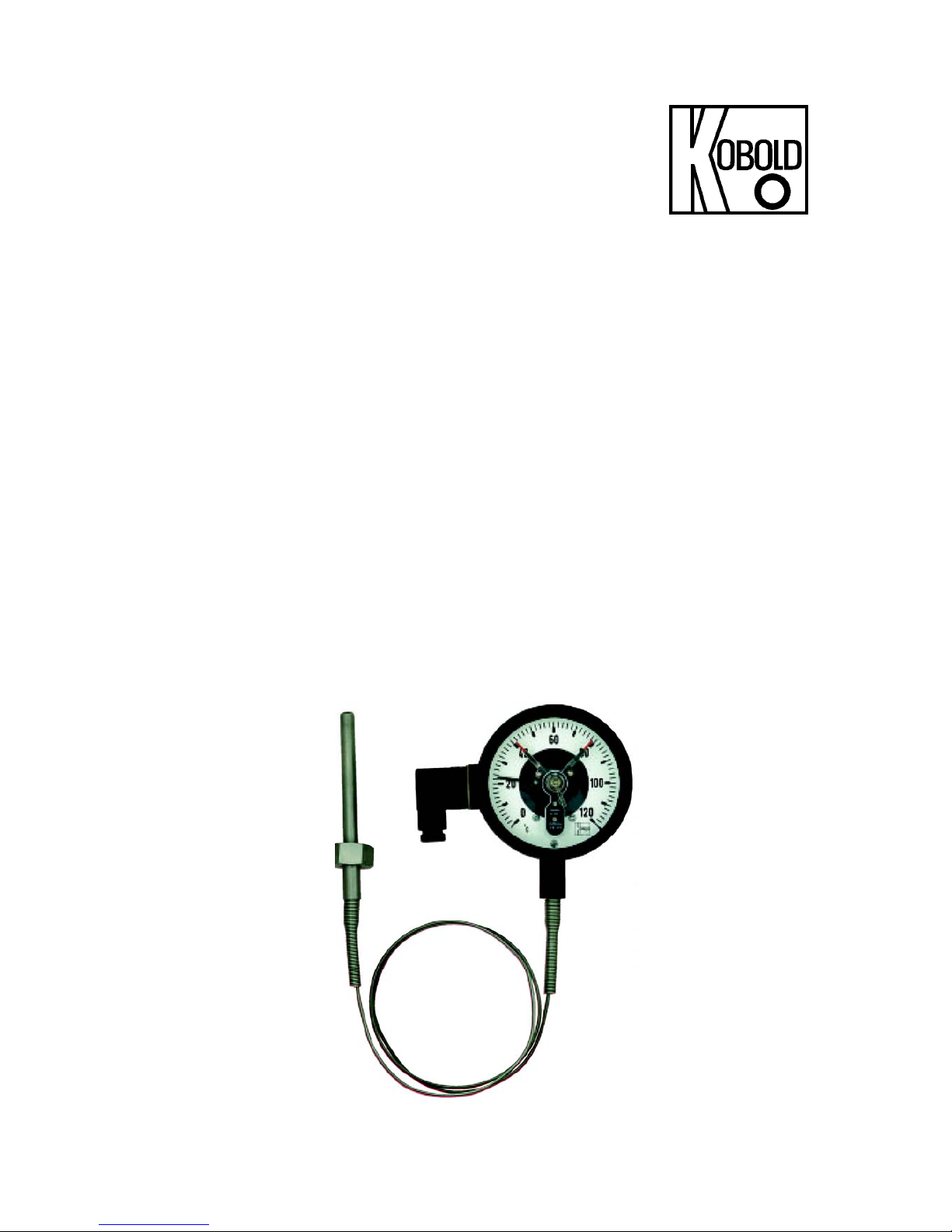
Series TNS/TNF Thermometers
Installation/Operation
KOBOLD Instruments Inc. 1801 Parkway View Drive Pittsburgh, PA 15205
Phone (412) 788-2830 • Fax (412) 788-4890
Precautions
• Please read the entire manual prior installing this
product. These instructions include information on
the TNS/TNF series capillary and rigid stem thermometers. Refer to the part number label on the
instrument housing to verify the exact model number.
• User’s responsibility: The TNS/TNF series thermometer are designed for use in a wide variety of
applications. It is however, the user’s responsibility to
ensure the suitability of the device with respect to a
specific application. Additionally, it is the user’s
responsibility to ensure the unit is properly installed
and tested prior to operation.
• Proper Installation and Sealing: Always use a
proper thread sealant with all installations. Be sure
not to overtighten fittings. Test for leaks prior to operating the instrument.
Instructions
• Wiring and Electrical: For units with switches,
check the current and voltage requirements for
the load to be controlled. Ensure that they do not
exceed the maximum specified switch ratings.
• Temperature and Pressure: Under no circum-
stances should the maximum ratings of operating
temperature and pressure be exceeded. Doing so
can result in equipment damage and personnel
injury.
• Material Compatibility: Ensure that the media
contacted parts are made of a material which is
chemically compatible with the process media.
Ensure that the housing material is compatible
with the ambient environment. Failure to do so
can result in equipment damage caused by chemical attack.
Electrical Connections:
For units with optional adjustable switches, all electrical connections are made via a weather proof 90° angle connector plug on
the side of the indicator housing. Connections are made via numbered screw terminals inside the connector. It is recommended
that a multi-conductor jacketed cable be used. The outside diameter of the jacket should be large enough to ensure that the
weather-tight cable gland on the plug can be tightened down
snugly.
Table 1 (back of page) lists all of the switch type codes and the
functional descriptions for each switch type. The switch type
code is stamped on the dial of the thermometer and is on the wiring diagram which appears on the thermometer housing. Consult
the wiring diagram on the thermometer housing for pin assignments for each switch.
5
6
4
3
1
2
TNS/TNF Terminal Housing
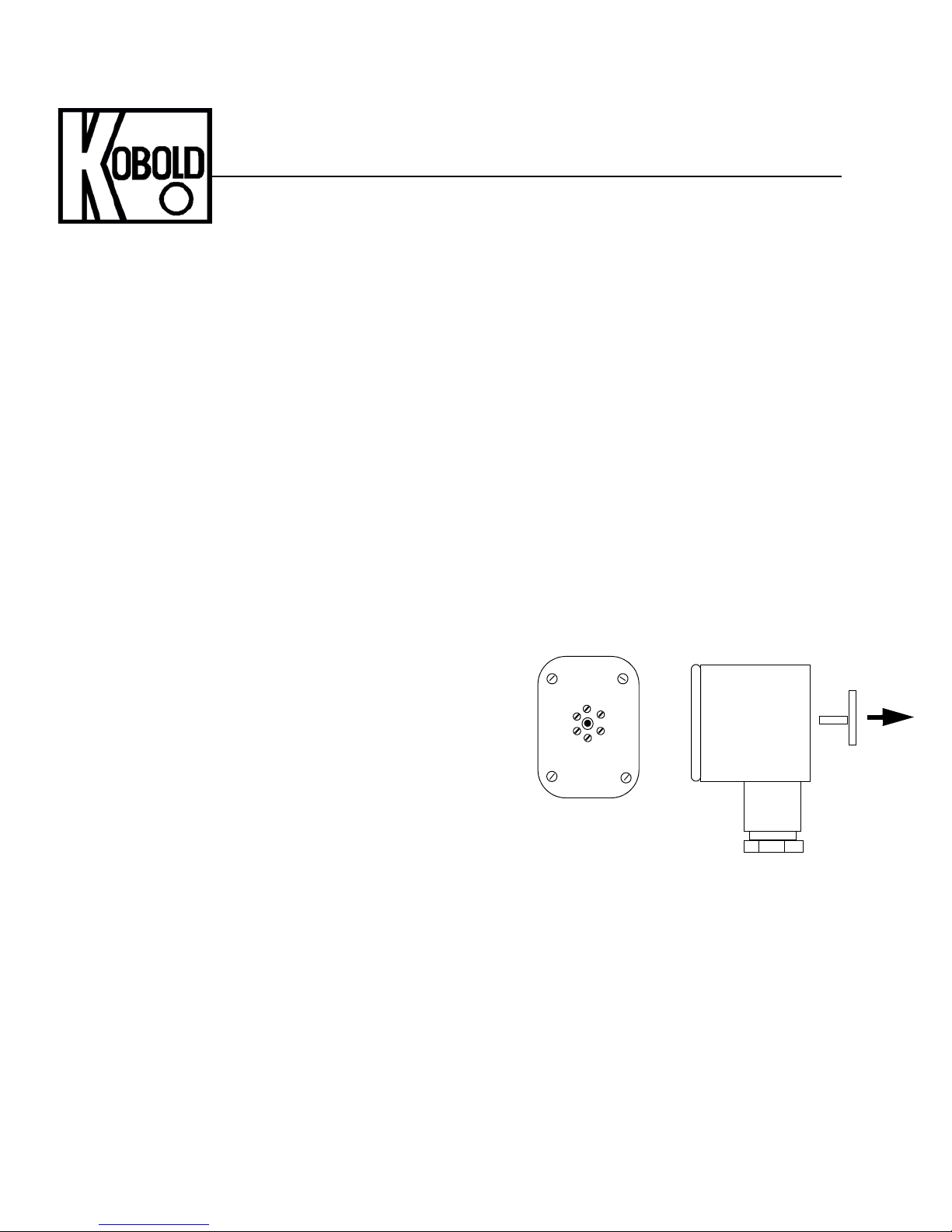
Setpoint Adjusting Tool
Switch Adjustment:
For units which have optional switches, adjust the switch setpoint as follows:
• Remove the switch adjusting tool by pulling it from the center of the 90° angle electrical connector.
• Insert the tool into the adjusting stub at the center of the dial crystal. The setpoint indicators are the ones with the red tips.
Push the adjusting tool in against spring tension and rotate until the adjusting lever contacts the setpoint indicator at its
base.
• Use the tool to rotate the setpoint indicator to the desired setpoint.
• Re-install the adjusting tool into the rear of the electrical connector.
FM Rev 02/27/04
Manual-TNS/TNF
Page 2
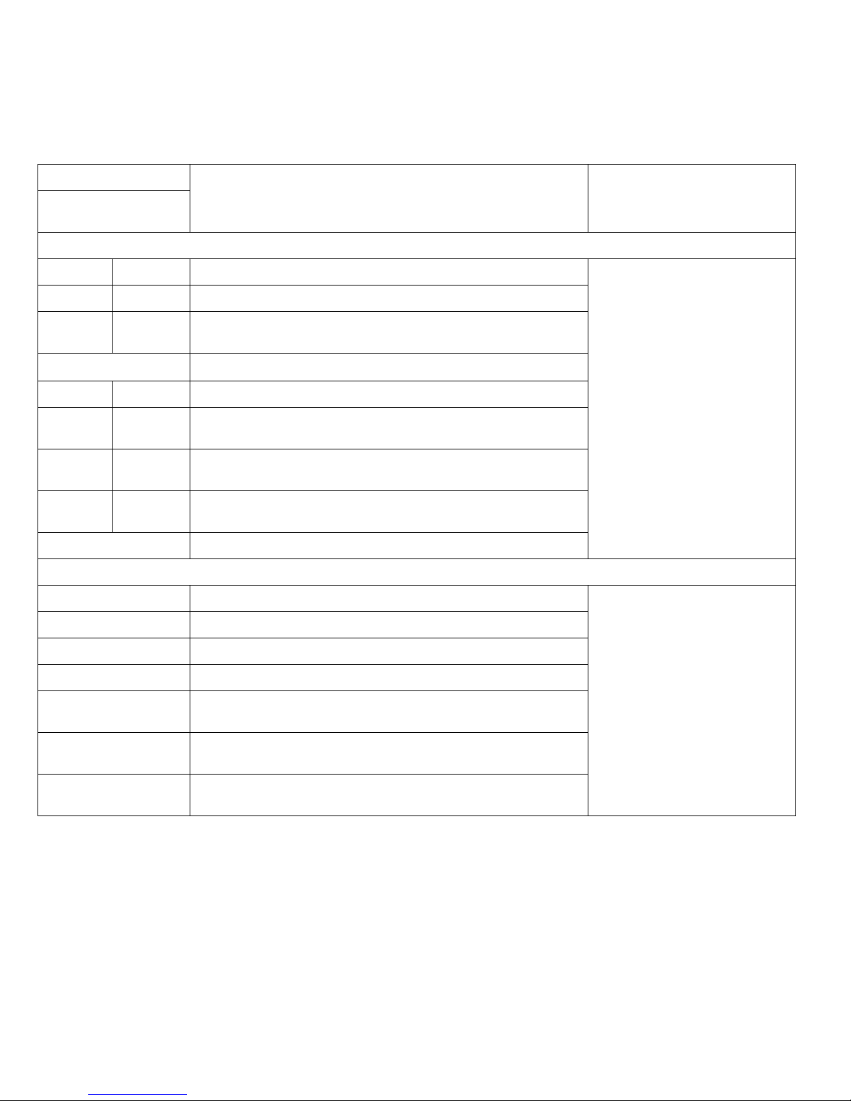
Table 1: Switching Options and Wring Terminal Numbers
Contact Type Code Functional Description
Sliding & Magnetic
Contacts
Single Contact
S10 M10 Single contact closes when temperature is above setpoint Sliding Contact Ratings
S20 M20 Single contact opens when temperature is above setpoint
S30 M30 Changeover (SPDT) contact switches over when temperature is
above setpoint
Max. Voltage: 250 VAC/VDC
Max. Power: 10 Watts
Max. Current: 0.6 Amps
Elec. Protection: NEMA 4X/ IP65
Two Contacts
S11 M11 Both contacts closed when temperature is above setpoint
S12 M12 First contact closed when temperature is above setpoint
Second contact open when temperature is above setpoint
S21 M21 First contact open when temperature is above setpoint
Second contact closed when temperature is above setpoint
S22 M22 First contact open when temperature is above setpoint
Second contact open when temperature is above setpoint
Inductive Contacts
Single Contacts
I10 Single switch activated when temperature is above setpoint Inductive Switch Rating
I20 Single switch de-activated when temperature is above setpoint
Two Contacts
I11 Both contacts activated when temperature is above setpoint
I12 First contact activated when temperature is above setpoint
Second contact de-activated when temperature is above setpoint
I21 First contact de-activated when temperature is above setpoint
Second contact activated when temperature is above setpoint
Magnetic Contact Ratings
Max. Voltage: 250 VAC/VDC
Max. Power: 30 Watts
Max. Current: 0.6 Amps
Elec. Protection: NEMA 4X/ IP65
Output: NAMUR Per DIN 19234
Elec. Protection: NEMA 4X/ IP65
I22 Both contacts de-activated when temperature is above setpoint
Mechanical Specifications
Materials of construction:
Measuring probe
2.5”, 3” and 10” dials: 304 stainless steel
4” and 6” dials: 316 stainless steel
Housing
3” and 10” dials: Painted steel or stainless
steel
4” and 6” dials: Aluminum or stainless steel
Capillary (TNF series only): 316 stainless steel
Capillary armor (option): 304 stainless steel
FM Rev 02/27/04
Maximum Pressure: 350 PSIG
Maximum Temperature: 1.3X measuring range
Page 3
Operating Instructions
for
Nitrogen Filled Thermometers
Model: TNS/ TNF
Page 4

TNS/TNF
page 2 TNS/TNF K01/0707
1. Contents
1. Contents ........................................................................................................ 2
2. Note .............................................................................................................. 3
3. Instrument Inspection .................................................................................... 3
4. Regulation Use .............................................................................................. 3
5. Operating Principle ........................................................................................ 4
6. Electrical Connection (Option)....................................................................... 4
6.1. Contacts ............................................................................................... 5
6.2. Switching Function Contacts ................................................................ 7
7. Installation ..................................................................................................... 8
8. Maintenance and Storage ............................................................................. 8
9. Technical Information .................................................................................... 9
10. Order Codes ............................................................................................... 10
Manufactured and sold by:
Kobold Messring GmbH
Nordring 22-24
D-65719 Hofheim
Tel.: +49(0)6192-2990
Fax: +49(0)6192-23398
E-Mail: info.de@kobold.com
Internet: www.kobold.com
Page 5

TNS/TNF
TNS/TNF K01/0707 page 3
2. Note
Please read these operating instructions before unpacking and putting the unit
into operation. Follow the instructions precisely as described herein.
The devices are only to be used, maintained and serviced by persons familiar
with these operating instructions and in accordance with local regulations
applying to Health & Safety and prevention of accidents.
When used in machines, the measuring unit should be used only when the
machines fulfil the EWG-machine guidelines.
3. Instrument Inspection
Instruments are inspected before shipping and sent out in perfect condition.
Should damage to a device be visible, we recommend a thorough inspection of
the delivery packaging. In case of damage, please inform your parcel service /
forwarding agent immediately, since they are responsible for damages during
transit.
Scope of delivery:
The standard delivery includes:
• Nitrogen Filled Thermometer, model: TNS/TNF
• Operating Instructions
4. Regulation Use
Any use of the Nitrogen Filled Thermometer, model: TNS/TNF, which exceeds
the manufacturer’s specifications, may invalidate its warranty. Therefore any
resulting damage is not the responsibility of the manufacturer. The user assumes
all risk for such usage.
Page 6
TNS/TNF
page 4 TNS/TNF K01/0707
5. Operating Principle
The measuring system of the gas pressure thermometer comprises probe,
capillary tube and Bourdon tube in a casing. These parts form a unit. The
complete measuring system is filled with pressurised nitrogen. A change in
temperature causes a change in inner pressure in the immersion shaft. The
resulting deflection of the Bourdon tube is transferred to the pointer through a
pointer element.
For the model TNF, the display and probe are connected by a capillary tube
separated by a distance up to 100 m.
A version filled with glycerine is available as an option for service at measuring
points exposed to strong vibrations. The fill dampens the measuring system when
exposed to mechanical vibrations and thus enables steady indication; it also
provides good lubrication for moving parts.
We recommend our robust aluminium casing for rough field service conditions.
These thermometers can also be used with aggressive measuring substances
when fitted with a suitable thermowell.
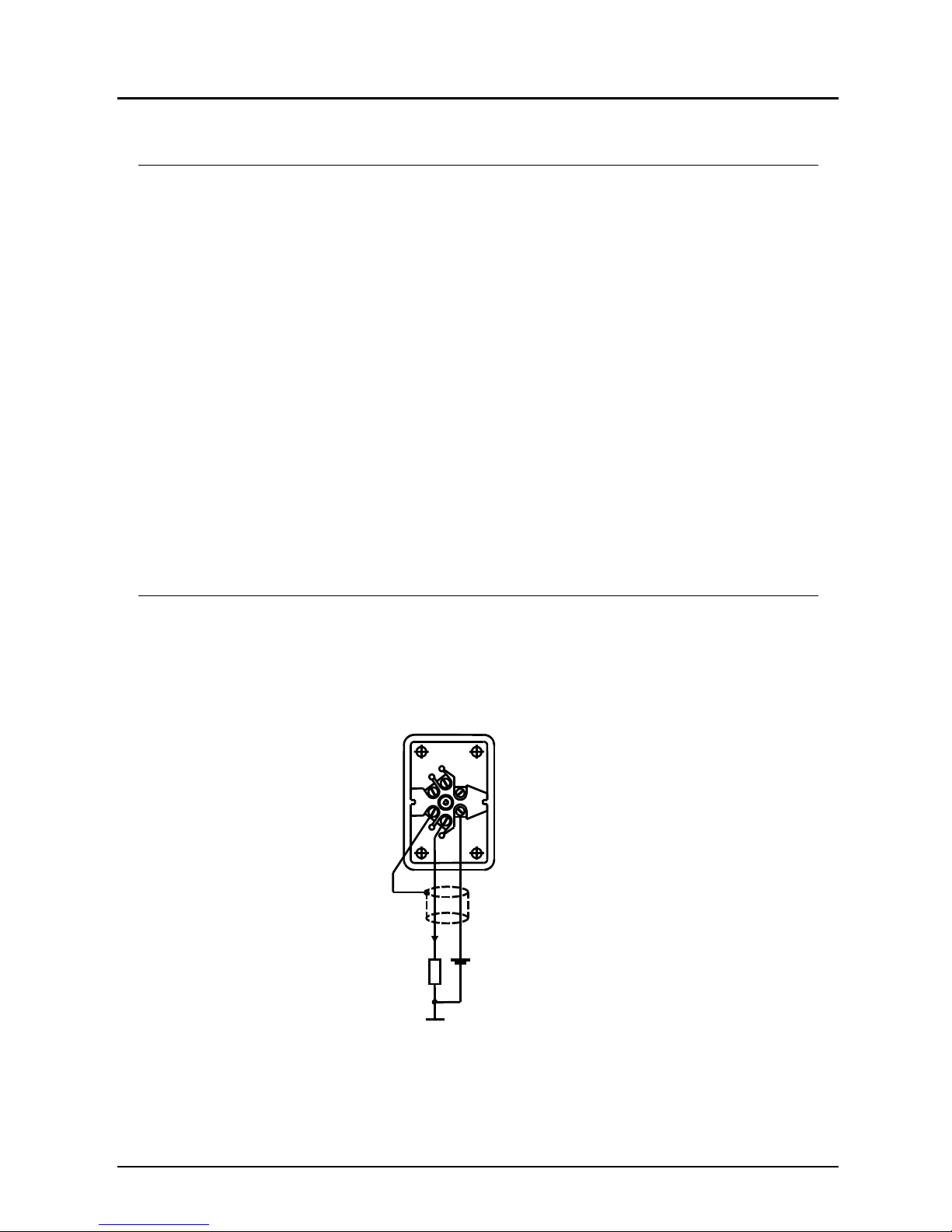
6. Electrical Connection (optional)
The electrical wiring diagram for the incorporated 2-wire transmitter with
4...20 mA output is given below. For all electrical parameters please see section
9. Technical Information: Transmitter.
4
5
3
2
6
1
24 VDC
R
+
-
GND
Screened twisted pair
Pin 1 = Power Supply
Pin 2 = GND (4... 20 mA)
Pin 3 = cable screen
4...20 mA
Page 7

TNS/TNF
TNS/TNF K01/0707 page 5
6.1. Contacts
(only for case diameters 100 and 160 mm )
Description
Electromechanical and electronic limit monitors serve to open and close electrical
switching circuits depending on the position of the instrument display. They are
suitable for fitting in casings with 100, 160 mm Ø.
The limit values are adjusted from outside with a setting lock. The limit monitor
is set with a detachable key to the value at which the switching operation is to be
carried out.
The construction of the limit monitor is such that the instrument can continue
operating past the setting pointer after successful contact operation.
The maximum setting range is approximately 270 degrees. Ambient
temperatures of –20 °C to +70 °C have no effect on the reliability performance.
We strongly recommend the use of our contact protection relays in applications
with high breaking capacities or vibrations, or for service in damping liquids (oil).
These relays have been specially designed for electromechanical limit monitors
and their use is mandatory.
The following contacts are available:
• Slow-action contacts
• Magnetic spring contacts
• Inductive contacts
6.1.1. Magnetic spring contacts
Magnetic spring contacts are suitable for service under almost all operating
conditions. They are almost completely insensitive to vibrations. The contact pin
carrier of the setting pointer is fitted with an adjustable magnet which pulls in the
wiper shortly before the set value is reached. Arcing is thus avoided and the pin is
prevented from being scorched. Because the magnetic force becomes effective
during the switching operation with this construction, the setting pointer must be
advanced or retarded by a differential gap of approximately 3–6% of full scale
value.
Switching voltage: max. 250 VAC/VDC
Breaking capacity: max. 30 W/50 VA
Switching current: max. 0.6 A
with standard contact material silver-nickel (Ag 80 Ni20)
Others on request.
Page 8

TNS/TNF
page 6 TNS/TNF K01/0707
6.1.2. Slow-action contacts
These contacting devices switch free of delay in the same way as the motion of
the actual-value pointer. They should be used where no contact loading is
required and the instruments are not exposed to vibrations. Due to sparking, the
contacting devices should not be used where there is a danger of explosion. Care
should also be taken that the contacting devices are not exposed to the effects of
aggressive vapours.
Switching voltage: max. 250 VAC/VDC
Breaking capacity: max. 10 watt / 18 VA
Switching current: max. 0.6 A
with standard contact material silver-nickel (Ag 80 Ni20)
6.1.3. Inductive contacts according to DIN 19234 (Namur)
The inductive contact device comprises mainly the control head (initiator)
attached to the setpoint pointer with its completely assembled encapsulated
electronics and mechanical assembly with moving control vane. The control vane
is moved by the instrument pointer (setpoint pointer). The control head is supplied
with DC voltage.
When the control vane is immersed in the air gap of the control head, its inner
resistance increases (damped condition, the initiator is high-resistive). The
resulting change in current intensity is the input signal for the switching amplifier
in the control unit.
Inductive contacts are suitable for service where explosion protection and high
reliability and switching rate, that is, long service life, are required.
Advantages of the inductive contact device:
• Long service life with non-contact switching
• Negligible reaction on the display
• Insensitive to aggressive environments (encapsulated electronics)
• Explosion protection, with control unit for service in zone 1 and 2 areas
Nominal voltage: 8 V
DC
(Ri = 1 kΩ)
6.1.4. Ex-protection
Thermometers with inductive contacts and external control unit can be used in
hazardous areas (zone 1 and 2). The necessary control unit should be installed
outside the ex-area.
Please refer to our brochure Z2 for details on control units.
Page 9

TNS/TNF
TNS/TNF K01/0707 page 7
6.2. Switching Function of Contacts
Magnetic spring contacts/slow-action contacts
Limit monitor with one contact
Switching
operation
Switching function
(when the limit value is exceeded)
Order code
Magnetic spring
contact
Order code
Slow-action
contact
Contact closes
..M10 ..S10..
Contact opens
Contact switches over, that is, contact
opens contact closes
..M20
..M30
..S20..
..S30..
Limit monitor with two contacts
First and second contact closes
..M11 ..S11..
1. Contact closes
2. Contact opens
..M12 ..S12..
1. Contact opens
2. Contact closes
..M21 ..S21..
First and second contact opens
..M22 ..S22..
Inductive contacts
Limit monitor with one contact
Switching
operation
When the thermometer pointer
moves clockwise and when the set
limit value is exceeded it causes the
following action:
Control action
Order code
inductive contact
moves the control vane out of the
control head
Control circuit is
closed
..I10..
moves the control vane into the control
head
Control circuit is
opened
..I20..
Limit monitor with two contacts
moves the control vane of the first and
second contact out of the control head
Control circuits
are closed
..I11..
moves the control vane of the first
contact out of the control head - moves
the control vane of the second contact
into the control head
Control circuits
are closed
..I12..
moves the control vane of the first
contact into the control head - moves
the control vane of the second contact
out of the control head
First control circuit
opens Second control
circuit closes
..I21..
moves the control vane of the first and
second contact into the control head
Control circuits are
opened
..I22..
Up to three contacts (up to four contacts in the aluminium case) can be delivered upon
request. The devices are delivered with lateral connecting box as standard. Other connectors
upon request.
Page 10

TNS/TNF
page 8 TNS/TNF K01/0707
7. Installation
Care must be taken to ensure that the bulb is not damaged during installation. Do
not attempt to bend bulb. The sensing bulb should be totally immersed in the
medium which is being measured. If a thermowell is being used, the heat transfer
delay can be improved by filling the thermowell with heat transfer substance (i.e.
graphite). When fitting bulb into a thermowell it is essential the bulb is not forced
against the bottom of the thermowell when tightening the nut. This can lead to
increase in pressure within the bulb and cause incorrect readings. The bulb
should be inserted into the thermowell until it bottoms and then withdrawn
approximately 5 mm before tightening compression nut to hand tight plus quarter
turn.
Check capillary is correct length by laying along proposed route. Never attempt to
stretch capillary as this will lead to fracture of the system.
The capillary should be securely supported and clipped to wall or other solid
surface and must be free from buckling and twists and have a minimum bending
radius of 60mm. Particular care should be taken at the points where the capillary
enters the case and the bulb. Excess capillary should be coiled and arranged in
free swinging loops between the last fixing point and the bulb.
Do not tighten instrument into the system by grasping the case, as any distortion
created will lead to calibration errors.
Instrument heads should be mounted in the vertical position unless otherwise
agreed with the manufacturer.
8. Maintenance and Storage
The function of the gauge does not require any special maintenance procedures
but frequent checks must be made to ensure that the instrument is still working
correctly and accurately. Any shift in temperature readings greater than twice the
tolerance of the instrument must be investigated and the immediate replacement
of the gauge if it is faulty.
Instruments should be stored in dry, clean conditions and care should be taken to
ensure the ambient temperature does not exceed or fall below the measuring
range of the instruments.
They must be protected against any impact damage.
Page 11

TNS/TNF
TNS/TNF K01/0707 page 9
9. Technical Information
Casing: Stainless steel 1.4301 with bayonet lock
aluminium (100 or 160 mm) with steel
ring cover, stainless steel or brass
chromium plated profile
casing: black steel, noryl black
Window: instrument glass 4 mm
with aluminium case: plexiglass
option: safety glass
Protection: IP 65
IP 54 with black steel
Dial: aluminium, white with black inscription
Pointer: aluminium, black
Pointer element: brass, option for 100 or 160 mm
casing: stainless steel
Measuring range: -40 to +40 – 0 to 600°C
Overload protection: full scale value, option 1.3 x full scale
Accuracy class: Ø 63 and Ø 80 category 1.6
Ø 100, Ø 160 and Ø 250 category 1
Nominal sizes: Ø 63, 80, 100, 160 and 250 mm
Probe: stainless steel 1.4301
with 100 or 160 mm casing
stainless steel 1.4571
Probe diameter: standard: 12 mm
option: 8, 9 or 10 mm
Probe length: to customer specification
Thread: stainless steel 1.4301
Capillary tube (for model TNF): stainless steel 1.4571
steel with PVC jacket
stainless steel 1.4571 with flexible
reinforced protective hose made of
1.4301 red copper
(not for 100 and 160 mm Ø)
Transmitter (optional):
Measuring range: See temperature range
Current output: 4 – 20 mA, 2-wire
Current output limit: max. 33 mA
Max. error F.S.: < 0.5%
Power supply: 13...25 VDC
Loop Resistance:
L
R =
(
)
mA20/V13V
plysup
−
Operating temperature: -20...+70 °C
Storage temperature: -20...+110 °C
Connection type: IP65
Protected against reversed polarity
Wiring: please see section 6.
Page 12

TNS/TNF
page 10 TNS/TNF K01/0707
10. Order Codes
For model: TNS
TNS- 1D 1 24 0A1 M12 Y
Model
Case material
Indicating range
Probe/ material /connection
Type of contact / function
Special version
For model: TNF
TNF-
1D 1 24 E A1 M12 Y
Model
Case material
Indicating range
Capillary material
Probe/material/connection
Type of contact/function
Special version
Please specify bulb and length of capillary tube (mm) in writing.
Page 13

TNS/TNF
TNS/TNF K01/0707 page 11
Design / case diameter for model: TNF
Case diameter
Design
63 80 100 160 250
TNF-0D TNF-0E TNF-0F TNF-0G TNF-0I
TNF-1D TNF-1E TNF-1F TNF-1G TNF-1I
TNF-2D TNF-2E TNF-2F TNF-2G TNF-2I
TNF-5D TNF-5E TNF-5F TNF-5G* TNF-5I
TNF-8D TNF-8E TNF-8F TNF-8G TNF-8I
TNF-6D TNF-6E TNF-6F** TNF-6G** -
Profile casing
96 x 96 mm 72 x 144 mm
TNF-Q91..
steel, black finish
TNF-R71..
noryl black
* with 160 mm high-grade steel case eccentric probe exit
** 100 and 160 mm casing in aluminium only
Page 14

TNS/TNF
page 12 TNS/TNF K01/0707
Design / case diameter
Case diameter
Design 63 80 100 160 250
TNS-0D TNS-0E TNS-0F TNS-0G TNS-0I
TNS-1D TNS-1E TNS-1F TNS-1G TNS-1I
TNS-AD
TNS-BD
TNS-CD
TNS-DD
TNS-AE
TNS-BE
TNS-CE
TNS-DE
TNS-AF
TNS-BF
TNS-CF
TNS-DF
TNS-AG
TNS-BG
TNS-CG
TNS-DG
TNS-AI
TNS-BI
TNS-CI
TNS-DI
TNS-8D TNS-8E TNS-8F* TNS-8G* TNS-8I
* with 100/160 mm st. steel case off-centre probe mounting
Case material
..2.. = stainless steel
..3.. = aluminium ring cover steel, black (for 100/160 mm casing only)
..A.. = aluminium ring cover stainless steel (for 100/160 mm casing only)
Scale ranges
°C °C °C
..24.. = -20 ... +40
..26.. = -20 ... +60
..35.. = -30 ... +50
..44.. = -40 ... +40
..46.. = -40 ... +60
..06.. = 0 ... +60
..08.. = 0 ... +80
..10.. = 0 ... +100
..12. .= 0 ... +120
..16.. = 0 ... +160
..20.. = 0 ... +200
..25.. = 0 ... +250
..30.. = 0 ... +300
..40.. = 0 ... +400
..50.. = 0 ... +500
..60.. = 0 ... +600
Special measuring ranges: upon request min. ∆ T = 60°C
Page 15

TNS/TNF
TNS/TNF K01/0707 page 13
Capillary tube (only for model: TNF)
..E..= stainless steel 1.4571 (standard) (1.4541 with 63, 80, 250 mm case
diameters)
..P.. = steel with PVC sheathing (only NG 100 / 160)
..F.. = stainless steel with flexible stainless steel reinforced hose (1.4301)
Please specify length of capillary tube (mm) when ordering.
Standard probe / material / connection (probe diameter: 12 mm)
for model: TNF
Description Material Thread Order code
Smooth probe Stainless steel Without
..A0..
Union nut Stainless steel
G 1/2
G 3/4
G 1
..B1..
..B2..
..B3..
Rotatable nipple
for DIN sleeve
Stainless steel
G 1/2
G 3/4
G 1
..41..
..42..
..43..
Union nut and
shoulder nipple
Stainless steel
G 1/2
G 3/4
G 1
1/2 NPT
3/4 NPT
1 NPT
..11..
..12..
..13..
..1A..
..1B..
..1C..
Sliding screwing
on extension
tube/probe
Stainless steel
G 1/2
G 3/4
G 1
1/2 NPT
3/4 NPT
1 NPT
..91..
..92..
..93..
..9A..
..9B..
..9C..
Sliding screwing
on capillary tube
Stainless steel
G 1/2
G 3/4
G 1
1/2 NPT
3/4 NPT
1 NPT
..81..
..82..
..83..
..8A..
..8B..
..8C..
Helix probe for
gases
Stainless steel Smooth probe
..H0..
Page 16

TNS/TNF
page 14 TNS/TNF K01/0707
Standard probe / meterial / connection (probe diameter: 12 mm)
for model: TNS
Description Material Thread Order code
Smooth probe Stainless steel without
..0A0..
Union nut Stainless steel
G 1/2
G 3/4
G 1
..0B1..
..0B2..
..0B3..
Simple nipple, rigid Stainless steel
G 1/2
G 3/4
G 1
1/2 NPT
3/4 NPT
1 NPT
..0C1..
..0C2..
..0C3..
..0CA..
..0CB..
..0CC..
Rotatable nipple for
DIN sleeve
Stainless steel
G 1/2
G 3/4
G 1
..041..
..042..
..043..
Union nut and
shoulder nipple
Stainless steel
G 1/2
G 3/4
G 1
1/2 NPT
3/4 NPT
1 NPT
..011..
..012..
..013..
..01A..
..01B..
..01C..
Sliding screw
on probe
Stainless steel
G 1/2
G 3/4
G 1
1/2 NPT
3/4 NPT
1 NPT
..0S1..
..0S2..
..0S3..
..0SA..
..0SB..
..0SC..
DIN 11851 with
polished probe,
for the milk and
food industry
Stainless steel
1" NW 25
1 1/2" NW 40
2" NW 50
3" NW 75
ANSI auf Anfrage
..0M3..
..0M5..
..0M6..
..0M7..
TRI-CLAMP
ISO 2852
with polished probe
Stainless steel
1" NW 25
1 1/2" NW 40
2" NW 50
ANSI auf Anfrage
..0T3..
..0T5..
..0T6..
Tuchenhagen®
with polished probe
Stainless steel
NW 10-15: Ø 31 mm
NW 25-32: Ø 50 mm
NW 40-50: Ø 68 mm
..0V3..
..0V5..
..0V6..
Helix probe
for gases
Stainless steel
..0H0..
Page 17

TNS/TNF
TNS/TNF K01/0707 page 15
Bulb length
Please specify when ordering. Minimum length 50 mm from the sealing collar of
the thread.
Special version (Please specify in writing when ordering)
Probe diameter 9 or 10 mm
Test certificate (5 measuring points)
Overtemperature protection (1.3 x)
Safety glass
Dual scale (°C/°F)
Measuring mechanism made of stainless steel (with 100 and 160 mm casing
only)
Max. pointer
Red gliding mark pointer
Casing filled with glycerine or oil
Knife edge pointer with fine graduation
Plug according to DIN 43650 with junction box (for unfilled casings only)
Tuchel-plug
 Loading...