

Page 1
KOBOLD Instruments Inc. 1801 Parkway View Drive Pittsburgh PA 15205
Phone (412) 788-2830 • Fax (412)-788-4890 • www.koboldusa.com
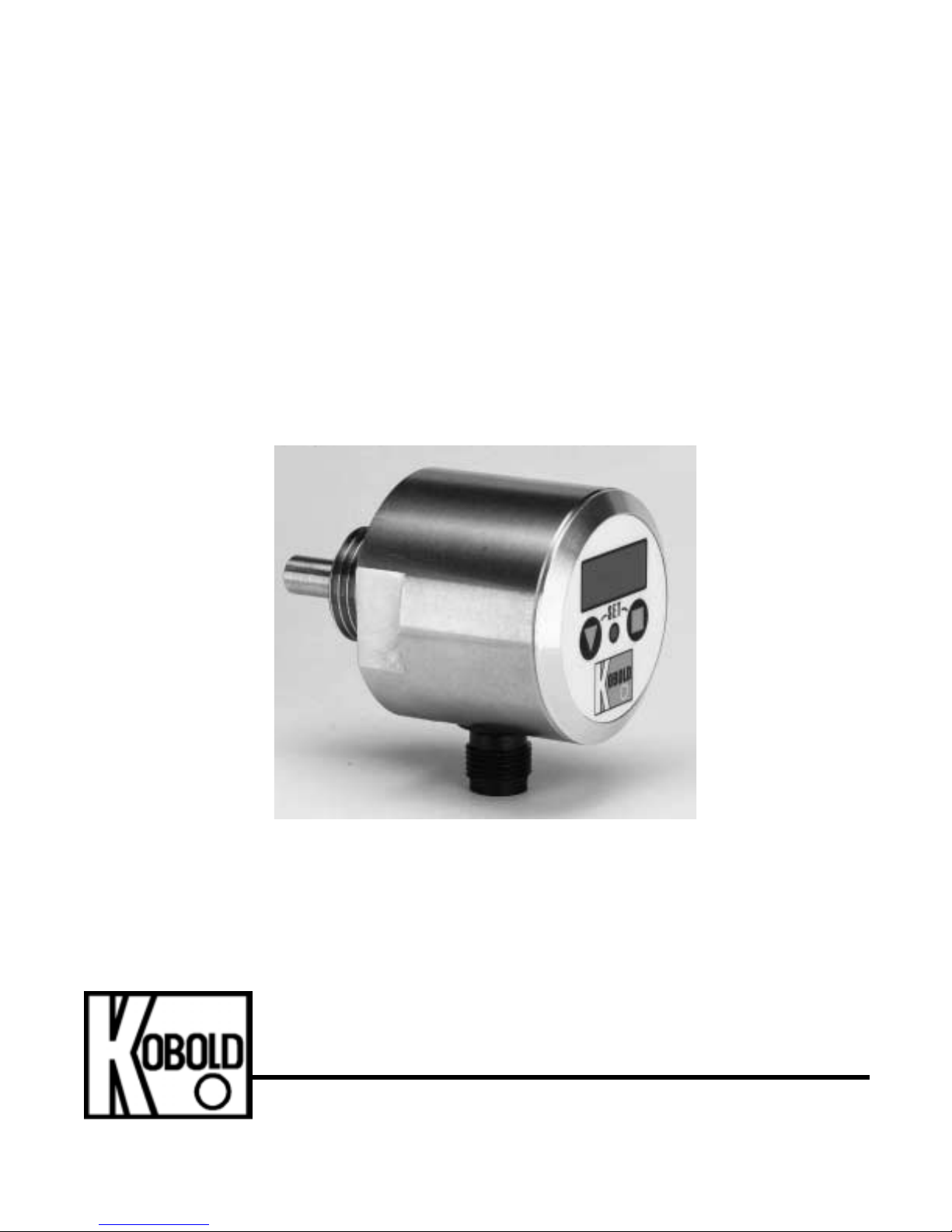
KOBOLD TDD Series Digital Temperature Switch
TDD-153 and TDD-3 53 Seri es
User Instructions
Manual-TDD_8-01
Page 2

Page 3

Table Of Contents
FM Rev . 8/6/01
TDD
KOBOLD TDD Series Digital Temperature Switch
1.0 General . . . . . . . . . . . . . .. . . . . . . . . . . .. . . . . . . . . . . . . . . . . . . . . . 1
2.0 Specifications . . . . . . . . . . .. . . . . . . . . . . .. . . . . . . . . . . . . . . . . . . . . . 1
3.0 Mechanical Installation . . . .. . . . . . . . . . . .. . . . . . . . . . . . . . . . . . . . . . 3
4.0 Electrical Installation . . . . .. . . . . . . . . . . .. . . . . . . . . . . . . . . . . . . . . . 4
5.0 Operation . . . . . . . . . . . . .. . . . . . . . . . . .. . . . . . . . . . . . . . . . . . . . . . 5
5.1 Programming Functions . . .. . . . . . . . . . . .. . . . . . . . . . . . . . . . . . . . . . 5
5.2 Programming Menu Item Descriptions . . .. . . . . . . . . . . . . . . . . . . . . . 8
6.0 Maintenance . . . . . . . . . . .. . . . . . . . . . . .. . . . . . . . . . . . . . . . . . . . . . 10
List Of Diagrams
Diagram 2.1 Dimensions . . . . . . .. . . . . . . . . . . .. . . . . . . . . . . . . . . . . . . . . . 3
Diagram 3.1 Electrical Connections . . . . . . . . . .. . . . . . . . . . . . . . . . . . . . . . 4
Diagram 5.1 Displays and Controls . . . . . . . . . .. . . . . . . . . . . . . . . . . . . . . . 5
Diagram 5.2 Program ming Functio ns . . . . . . . .. . . . . . . . . . . . . . . . . . . . . . 5
Diagram 5.3 Sequence to C hange a Val ue . . . .. . . . . . . . . . . . . . . . . . . . . . 6
Diagram 5.4 Program ming Flowchar t . . . . . . . .. . . . . . . . . . . . . . . . . . . . . . 7
List of Tables
Table 2.1 Part Number Identification . . . . . . .. . . . . . . . . . . . . . . . . . . . . . 2
Page 4

Page 5

TDD
FM Rev. 8/6/01
CAUTION: For safety reaso ns, please read the cautionary informati on located at
the end of the manual, before attempting installation.
1.0 General
The KOBOLD TDD Series is a solid state, electronic temperature switch which employs
a Pt-100 R TD as the heart of the sensing system. The measuring p robe and hou sing ar e
constructed of 316L stainless steel providing excellent corrosion resistance. The TDD’s
microprocessor based electr onics allow the user to program a setpoint, adjust switching
hysteresis, dampening and switch logic. There is virtually no calibration drift over its
service life.
In addition to the switch output, t he TDD has a d i g ital display for local indicati on of
temperature.
2.0 Specifications
Available Switching Ranges: 0°F to 250°F or -20°C to
120°C
Display Ty pe: 3 Digit LED
Resolution: ±0.5° below 100°
±1° for 100° and above
Switch Status: Red LED on when
Temperature is above setpo int
Accuracy (worst case)
32°F to 160°F: ±1°F
0°F to 31°F: +6°F/-2°F
161°F to 230°F: +2°F/-4°F
231°F to 250°F: +2°F/-5°F
Sensor Element: Pt-100 RTD
Maximum Pressure: 1 150 PSIG
sensing Probe Material: 316L Stainless steel
Housing Material: 316L Stainless steel
Electrical Data
Switch Type: Open collector, NPN or PNP
based on model number,
programmable N/O or N/C
Switch Rating: Max. 300 mA, short circuit
protected
Response Time: 50 mSec.
Power Supply Requirement: 24 VDC ±20%, 40 mA Max.
Electrical Connection: M-12 male, Micro-DC
Electrical Protecti on: NEMA 4X/IP 65
Page 6

TDD 2
FM Rev. 8/6/01
Table 2.1 Part Number Identification
TDD = Compact Electronic Temperature Switch
153 = PNP transistor switch Output Type
353 = NPN transistor switch
N4 = 1/2” NPT Fitting
N5 = 3/4” NPT
Range
TDD - 353 - N4 - F2 Example
F2 = 0 to 250°F
H2 = -20 to 120°C
Page 7

3TDD
FM Rev. 8/6/01
Diagram 2.1 Dimensions
3.0 Mechanical Installation
The following genera l installa tion instructions and pr ecautio ns must be followed to in sure
proper, reliable switch operation:
1. Select a suitable location on the piping system for installation. Installation in a
location where sediments can collect on the switch’s temperature sensing
probe (such as the underside of a horizontal piping run) will cause sluggish or
faulty operation.
2. The switch should not be installed directly on top of a horizontal pipi ng run (12
O’clock position). Air pockets which can form at the top of the pipe will prevent
the measuring probe from obtaining accurate temperature measurement.
Mounting at the 2 O’clock to 5 O’clock or the 7 O’c lock to 10 O’clock position is
best.
3. The ambient temperature range which the switch can withstand is -4°F to
+140°F. If the switch is located outdoors in a cold environment the switch must
be protected from excessively cold temperatures with insulated heat tracing or
by other suitab le means. In hot environments the switch should be located in
an area where the ambient temperature does not exceed 140°F.
4. In order to obtain an accurate measurement of the bulk flui d temperature in a
pipe, the fitting into which the switch is installed must allow the sensing probe
tip to protrude past the ID of the pipe and into the flow stream. The turbulent
fluid flow will then promote mixing and yield an accurate measurement.
1.75
0.93
1.68
1.56
41 mm
Std. connec t or
M-12 x 1
1.89
.47
.45
.28
A
B
1/2” NPT
2.76
3/4” NPT
2.78
Dimensions in inches unless otherwise noted
Page 8

TDD 4
FM Rev. 8/6/01
4.0 Electrical Installation
The following electrical installation instructions and precautions must be followed to
insur e proper switch and analog output operation. Failure to follow these instructions
may result in irreparable damage to the switch:
1. The unit employs an open collector NPN or PNP transistor switch. To verify
which model you are installing, check the model number codes in Section 2.0,
Specifications. When the PNP version activates, it connects the DC supply
voltage to the switch output pin. When the NP N version activates, it connects
the DC ground to the switch output pin.
2. This switch can only switch fixed polarity DC loads with a maximum current
draw of 300 mA. To switch higher current DC loads or AC loads use an
appropriately sized relay.
3. In order to minimize electromagnetic noise pickup, a jacketed instrument and
control cable with shield should be used. The shield should be connected to
the power system earth ground at one end of the cable only.
Diagram 4.1 Electrical Connectio ns
Typical Wiring
1
2
3
4
Switch Out
Not
Connected
-DC
+ DC Supply
24 VDC ±20%
Optional Mating Connector
Brown = 1 = +DC
White = 2 = Not Connected
Blue = 3 = -DC
Black = 4 = Switch Out
TDD-153...
1
4
3
+DC
Switch Out
-DC
Load
PNP Switch Version
+
-
TDD-253...
1
4
3
+DC
Switch Out
-DC
Load
+
-
NPN Switch Version
Page 9

5TDD
FM Rev. 8/6/01
5.0 Operation
Diagram 5.1 Displays and Controls
5.1 Programming Functions
The TDD digital Temperature switch is programmed via membrane push-buttons on the
faceplate of the switch as shown in the following figure:
Diagram 5.2 Programming Functions
.
Switch Status LED
On = Temperature Above Setpoint
Off = Tem perature Below Setpoint
Press to enter a menu
program m ing bran ch,
or change a display v al ue
Hold for 3 seconds
to enter programm ing
me nu. Press to step
through menu
During Normal Operation
:
:
Press for 3 Sec to Enter Setup Mode
Display Switch Point/ Window Point
During Setup Mode
: Next Step
: Change Values
Press 3 sec
Exit Setup
Orfor20sec
Press no buttons
Page 10

TDD 6
FM Rev. 8/6/01
5.1.1 Changing Values in Setup Mode
When in the S etu p Mode the actual values of setpoint, hysteresis, switch logic and other
functions are adjusted as required by the user . Fro m the main menu (e.g. switching point
“SPo”), press the “▼” button to adjus t tha t functions value . The follow i ng diagram shows
the sequence of steps required to change a value:
Diagram 5.3 Sequence to Change a Value
Speichern
Save Value
Press “▼” to get from the main menu
Set the fi rst digit
Set the second digit
Set the third digit
Set the decimal point
location
reset value
or
Page 11

7TDD
FM Rev. 8/6/01
5.1.2 Programming Flow Chart
Diagram 5.4 Programming Flowchart
7 Steps
Switch Logic
Filter
Window Point
Hysteresis
Setpoint
N/O
3 sec
C
o
d
e
=
N/C
Save
Enter Code
Change Code
Change Value
Change Value
Change value
Change Value
(Enter Code)
Enter New Code
Page 12

TDD 8
FM Rev. 8/6/01
5.2 Programming Menu Item Descriptions
After the “▼” Button is depressed for three seconds to enter the setup mode, and the
lockout code is entered (if lockout is en abled) , the programmi ng menu may be accessed.
Diagram 5.3 provides a flowchart of the programming menu. Section 5.1.1 and di agram
5.2 provide details on how to change the value of each menu item parameter. The
following is a detailed description of each menu item.
5.2.1 Cod - Code
If the lockout featu re was enabled during a prior setup , the user cod e which was sele cted
at that time mu st be entered. Section 5.1.1 ‘Changing Values in Setup Mode’ on page 6
provides steps required to enter the value.
5.2.2 SPo - Switchpoint
This menu ite m allow s the user to input t he desired switching point. Any number between
-199 and 999 can be entered. Additionally, a decimal point can be added if desired.
Section 5.1.1 ‘Changing Values in Setup Mode’ on page 6 provides steps required to
change a value. If the measured temperature exceeds the switchpoint value, the switch
will activate.
5.2.3 HYS - Hysteresis
This menu item allows the user to set a deadband value bel o w the switchpo int such tha t
the switch will not de-activate until the measured temperature falls below the setpoint,
minus the hysteresis va lue. The hysteresis value will always be a negative value an d can
be set as any number between 0 and -199. Additionally, a decimal point can be added if
desired. Section 5.1.1 ‘Changing Values in Setup Mode’ on page 6 provides steps
required to change a value.
Example: Switchpoint Value (SPo) is set at 50.0
Hysteresis Value (HYS) is set at -5
The switch will activate (LED on) when measured temperature is above
50.0 and will de-activate (LED off) when measured temperature is below
45.0.
Temperature
Switch
On
Off
Temperature
Switch
On
Off
Case 1:
Case 2:
Switch set as Switch set as
Normally Open Normally Closed
45.0
50.0
45.0
50.0
Page 13

9TDD
FM Rev. 8/6/01
5.2.4 duo - Window Point
This menu item allows the user to set a value above the switchpoint such that a
temperature band, or window can be monitored.
Note: The duo value must be a positive number and it must be a larger value that the
SPo value. If it is not, an error message is displayed. If the error occurs both the
SPo value and the duo values are cleared and must be re-entered.
Additionally, a decimal point can be added if desired. Section 5.1.1 ‘Changing Values in
Setup Mode’ on page 6 provides steps required to change a value. When the measured
temperature is above the switchpoint, the switch will activate. The switch will de-activate
when the measured Temperature either increases to above the window point value or
decreases to below the switchpoint value. The window point can also used with the
hysteresis function if desire d.
Example: Switchpoint Value (SPo) is set at 50
Window Point (duo) value is set at 75
Hysteresis Value (HYS) is set at -5
The switch will activate (L ED on) when measured Temperature is above
50.0 and will de-activate (LED off) when meas ured Tempera ture is above 80
(75 + 5) or below 45 (50 - 5).
5.2.5 Filt - Filtering
This menu item allows the user to average the measured output over 1, 2, 4, 8, 16, 32 or
64 samples. Section 5.1.1 ‘Changing Values in Setup Mode’ on page 6 provides steps
required to change a value. Adding filtering provides a more stable display and prevents
false switching for systems in which spurious temperatu re fluctuations are a prob lem. The
larger the number of samples the more stable the display and switch. A Filt value of “1”
shuts off the filtering.
When filtering is being used, the TDD series employs an integrated overshoot function
which detects any overshoot above 6.25% and processes that measured value without
filtering. This feature allows the switch to differentiate between spurious fluctuations and
Temperature
Switch
On
Off
Temperature
Switch
On
Off
Case 1: Switch set as
Case 2: Switch set as
Normally Open
Normally Closed
45
50 75
80
45
50
75
80
Page 14

TDD 10
FM Rev. 8/6/01
actual system tempera ture changes and process the tempera ture change signals without
filtering. This greatly enhances the switch’s response time when the filtering function is
being used.
5.2.6 Con - Switch Logic
This menu item allows the user to select the output switch logi c as either normally closed
(nc), or normally open (no):
Normally Open: Switch activates when measured temperature is above the
switchpoint.
Normally Closed: Switch activ ates when mea sured temperature is below the
switchpoint.
5.2.7 CCo - Change Code
This menu item allows the user to set a pass code which will lock out the programming
functions. This protects the devi ce from un-authorized access to the setup men u. Section
5.1.1 ‘Changing Values in Setup Mode’ on page 6 provides steps required to change a
value. The code can be any value from 000 to 999. A code of 000 disables the lockout
function. A value other than 000 will require entry of that code to access the setup menu.
6.0 Maintenance
The TDD series temperature switches have no moving parts and are therefore virtually
maintenance free. Depending on the type of media, the temp erat ure sensing pro be may
become coated over time. Sluggish response to changes in system temperature would
be evidence of this. If coating occurs, remove the switch from the system and clean the
temperature sensing probe.
Page 15

CAUTION
PLEASE READ THE FOLLOWING WARNINGS BEFORE AT TEMPTING
INSTALLATION OF YOUR NEW DEVICE. FAILURE TO HEED THE
INFORMATION HEREIN MAY RESULT IN EQUIPMENT FAILURE AND
POSSIBLE SUBSEQUENT PERSONAL INJURY.
Page 16

TDD 12
FM Rev. 8/6/01
• User's Responsib ility f or Safe ty: K OBOLD manufactur es a wide range of
process sensors and technologies. While each of these technologies are
designed to operate in a wide variety of applications, it is the user's
responsibility to select a technology that is appropriate for the application,
to install it p roperly, to perfo rm tests of the installed system, and to maintain
all components. The failure to do so could result in property damage or
serious injury.
• Proper Installation and Han dling: Use a proper thread sealant with all
installations. Take care not to overtighten the fittings. Always check for
leaks prior to system start-up.
• Wiring and Electrical: Section 2.0, Specifications and Section 4. 0,
Electrical Connections, provide the voltage and current limitations and the
wiring for the various sensor types. The sensor electrical ratings should
never be exceeded. Electrical wiring of the sensor should be performed in
accordance with all applicable national, state and local codes.
• Pressure and Temperature: Section 2.0, Specifications, provides the
pressure and temperature limits for each model. Operation out side these
limitations will cause damage to the unit and can potentially cause personal
injury.
• Material Compatibility: Make sure that the model which you have
selected is chemically compatible with the application liquids. While the
meter is liquid and spray resistant when installed pr operly, it is not
designed to be immersed.
• Flammable, Explosive and Hazardous Applications: The TDD series is
not an intrinsically safe or explosion proof design. They should not be used
in installations in which an instrinsically safe or explosion proof design is
required.
• Make a Fail-safe System : Design a fail-safe system that accommodates
the possibility of switch or power failure. In critical applications, KOBOLD
recommends the use of redundant backup systems and alarms in addition
to the primary system.
Page 17

Page 18

 Loading...