

Page 1
Operating Instructions
for
Electronic Temperature Sensor
Model: TDA
Page 2

TDA
1. Contents
1. Contents ........................................................................................................ 2
2. Note .............................................................................................................. 3
3. Instrument Inspection .................................................................................... 3
4. Regulated Use .............................................................................................. 3
5. Operating Principle ........................................................................................ 4
6. Mechanical Connection ................................................................................. 4
7. Electrical Connection .................................................................................... 5
7.1. Connector pin assignment TDA-...L3M ................................................ 5
7.2. Connector pin assignment TDA-...P3M, TDA-...N3M ........................... 6
8. Operation ...................................................................................................... 7
8.1. Button function ..................................................................................... 7
9. Settings ......................................................................................................... 8
9.1. Value setting ........................................................................................ 8
10.Set-up Mode ................................................................................................. 9
10.1. TDA-...L3M, TDA-...L3P, TDA-...L3S ................................................... 9
10.2. TDA-...P3M, TDA-...N3M ................................................................... 10
11.Main Menu Items......................................................................................... 12
11.1. Current output .................................................................................... 12
11.2. Switching point ................................................................................... 12
11.3. Hysteresis .......................................................................................... 12
11.4. Window point (duo-point) ................................................................... 12
11.5. Switching behaviour ........................................................................... 13
11.6. Transient response ............................................................................ 14
11.7. Contact type ....................................................................................... 14
11.8. Change code ..................................................................................... 14
12.Maintenance ............................................................................................... 14
13.Technical Information .................................................................................. 15
14.Ordering Codes ........................................................................................... 16
15.Dimensions ................................................................................................. 17
16.EU Declaration of Conformance .................................................................. 18
Manufactured and sold by:
Kobold Messring GmbH
Nordring 22-24
D-65719 Hofheim
Tel.: +49(0)6192-2990
Fax: +49(0)6192-23398
E-Mail: info.de@kobold.com
Internet: www.kobold.com
page 2 TDA K01/0416
Page 3

TDA
2. Note
Please read these operating instructions before unpacking and putting the unit
into operation. Follow the instructions precisely as described herein.
The devices are only to be used, maintained and serviced by persons familiar
with these operating instructions and in accordance with local regulations
applying to Health & Safety and prevention of accidents.
When used in machines, the measuring unit should be used only when the
machines fulfil the EC-machine guidelines.
3. Instrument Inspection
Instruments are inspected before shipping and sent out in perfect condition.
Should damage to a device be visible, we recommend a thorough inspection of
the delivery packaging. In case of damage, please inform your parcel service /
forwarding agent immediately, since they are responsible for damages during
transit.
Scope of delivery:
The standard delivery includes:
Electronic Temperature Sensor, model: TDA
Operating instruction
4. Regulated Use
Any use of the Electronic Temperature Sensor, model: TDA which exceeds the
manufacturer’s specifications may invalidate its warranty. Therefore any resulting
damage is not the responsibility of the manufacturer. The user assumes all risk
for such usage. The application specifications include the installation, start-up
and service requirements specified by the manufacturer.
TDA K01/0416 page 3
Page 4

TDA
5. Operating Principle
The KOBOLD Model TDA temperature sensor is used for economical measuring
and monitoring of temperature. It can be used for any application in which
temperatures must be monitored with great accuracy.
The sensor element is a semiconductor that outputs a digital signal to the
electronic analyser in 0,5°C steps. The measured values are shown on a 3-place
LED display. The analogue output can be adjusted as required with the
measuring range.
6. Mechanical Connection
Before installation:
Make sure the maximum operating pressure and maximum service
temperature for this instrument are not exceeded.
Installation:
This device is installed in a matching sleeve. Use sealing tape (i.e. Teflon tape)
or a flat gasket to seal the threaded connections.
The mounting position should be selected so that the sensor tip is always
immersed in the liquid being monitored, thus ensuring optimal heat exchange
between the liquid and the temperature sensor.
Note that deposits that build up on the senor tip or dirty liquids can have an
insulating effect and cause invalid measurements.
Whenever possible, after the mechanical installation is complete, the joint at
the threaded connector and the supply piping should be checked to ensure
that it is tight and does not leak.
page 4 TDA K01/0416
Page 5
TDA
7. Electrical Connection
Caution! Be sure that the supply voltage of your system is the same
as that specified on the device nameplate.
Make sure that the electrical supply lines are de-energized.
Make the connection using a PVC cable or the M 12x1 connector socket, as
shown in the accompanying diagram.
Appropriate connectors with different cable lengths are optionally available.
Important! The instrument electronics may be damaged if the
connectors are assigned incorrectly.
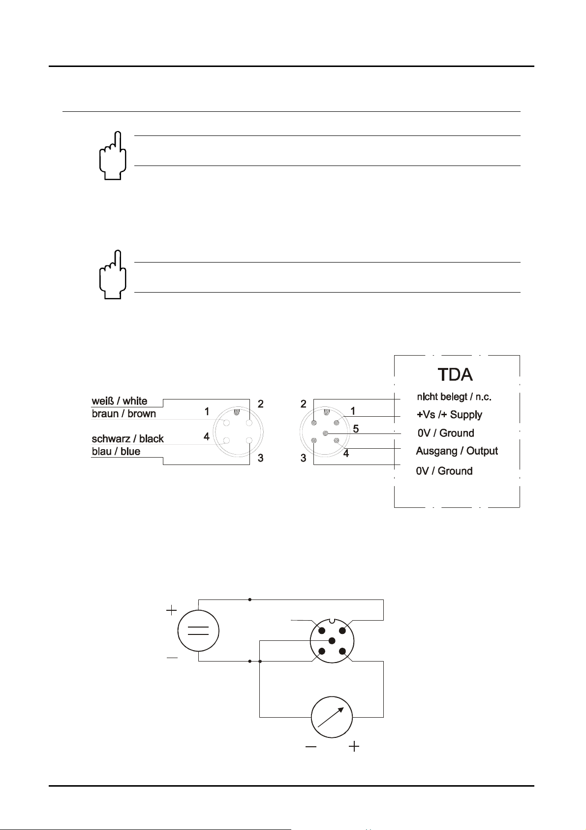
7.1. Connector pin assignment TDA-...L3M
Option:
n.c.
GND
Plug
2
3
1
+Vs
Analog Out
0(4)-20mA
4
Socket wit h cable
Connection example
TDA-...L3M/Plug M12
+Vs
GND
TDA K01/0416 page 5
Page 6
TDA
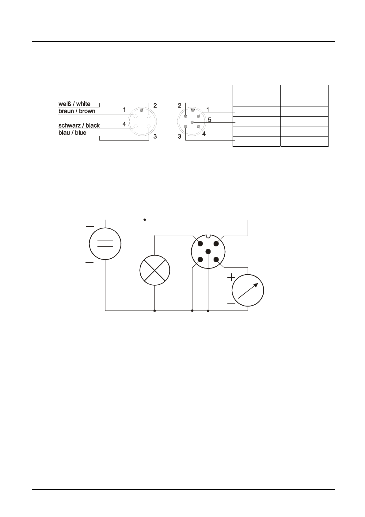
7.2. Connector pin assignment TDA-...P3M, TDA-...N3M
TDA-...P3M TDA-...N3M
PNP-Output NPN-Output
+24 VDC +24 VDC
0 V / GND 0 V / GND
0(4)-20 mA 0(4)-20 mA
Option:
Socket wi t h cab le
Cable connector assignment
Plug
0 V / GND 0 V / GND
TDA-...P3M
Power
+Vs
PNP out
GND
Plug M12
2
3
5
GND
1
4
mA
+24 V
0(4)-20 mA
DC
page 6 TDA K01/0416
Page 7

TDA
8. Operation
Caution! Please note that when used in high temperature
applications, the device housing and the operating controls can
become very hot.
Connect the temperature sensor as shown in the previous wiring diagram and
then connect it to a power source of the specified voltage.
8.1. Button function
In the normal mode (measuring mode)
: Press 3 secs Set-up mode
In the set-up mode
: Next Step
Any time
3 sec
: Change Value
or do not press
a button for 20 sec
Standard mode
TDA K01/0416 page 7
Page 8

TDA
9. Settings
The following values can be changed at the temperature transmitter:
Scale Range Factory Setting
Start current (S-C)
End current (E-C)
Start current selection (SCS)
Change code (CCo,)
0...FS 0
0...FS FS
0 / 4 4
000...999 000
9.1. Value setting
From the main menu item (for example: start current, "S-C"), press the ""
button to set the value. The flow chart below illustrates the universal routine for
changing individual parameters.
[From the main menu item]
1. Adjust position
save
[To the next main menu item]
2. Adjust position
3. Adjust position
Adjust decimal point
Save selected value
or
Enter new value
page 8 TDA K01/0416
Page 9

TDA
10. Set-up Mode
10.1. TDA-...L3M, TDA-...L3P, TDA-...L3S
3 sec
Codeinput
Setting parameter
Code=
Startcurrent
End current
Startcurrent
Selection
7sec
Setting parameter
7sec
Setting parameter
0-20
mA
7sec
Save
4-20
mA
Setting paramter
TDA K01/0416 page 9
Page 10

TDA
10.2. TDA-...P3M, TDA-...N3M
3 sec
Code input
setting parameter
Code=
Switch pt.
setting parameter
Hysteresis
On-Delay
Off-Delay
Contact type
N/C contact
N/O contact
setting parameter
setting parameter
setting parameter
Save
page 10 TDA K01/0416
Page 11

TDA
Start current
7sec
setting parameter
Endcurrent
7sec
setti ng pa ra me t er
0-20
Start current
mA
Chan g e code
7sec
4-20
mA
setting parameter
Save
TDA K01/0416 page 11
Page 12

TDA
11. Main Menu Items
11.1. Current output
The current output is selected as follows:
"S-C" Start current indicated value < > 0(4) mA
"E-C" End current indicated value < > 20 mA
"SCS" Start current selection (0-20 mA or 4-20 mA).
The indicated value at which 0(4) mA flows is entered in menu item “S-C”. The
indicated value at which 20 mA flows is entered in menu item “E-C”.
11.2. Switching point
The switching point is entered in the menu item "SPo". A setting value between
-199 and 999 can be selected. This value can also include a decimal point. The
decimal point can be set at two points (e.g. 10.0 or 1.00). If the measuring value
is the set switch point, the temperature switch is activated and is signalised by a
lighted LED.
If the hysteresis is zero and the window point is inactive, the temperature switch
will be reacted if the temperature is below the switch point.
11.3. Hysteresis
After setting the switching point, the hysteresis can be entered as a negative
value in the "HYS" menu. The standard hysteresis value is zero. In operation
condition this can lead to ambiguous switching behaviour if the reading fluctuates
around the switching point or window point. This can be prevented by increasing
the hysteresis. The hysteresis relates to the switching point and the window point
(switching point minus hysteresis; window point plus hysteresis).
Example: Switching point 100 °C; Hysteresis: -2.5 °C
The temperature switch switches when 100 °C is exceeded and
switches back when the reading drops below 97.5 °C.
11.4. Window point (duo-point)
Along with the switching point, the "duo" (duo-point) has to be defined, known as
the window point. This must be higher than the switching point. By using the
window point and the switching point it is possible to monitor the measurement
value in a certain range. The switching point limits the measurement range to
smaller values and the window point to larger values.
If the window point (duo-point) is less than or equal to the switching
point, an error report (Er4) will be indicated on the display. The
value is deleted and its function is invalid (in the case that the
window point and switching point out of adjustment).
page 12 TDA K01/0416
Page 13

TDA
The value is set in the same way as the switching point.
The window point is needed for process, monitoring of a certain temperature
range.
Example: Switching point: 50 °C; window point: 70 °C; hysteresis: -2 °C
The temperature contact switches when 50 °C is exceeded.
If the temperature remains between 48 °C (50-2) and 72 °C (70+2), the contact
will remain in active switching condition (LED on). If it exceeds 72 °C or drops
below 48 °C , the contact will de-energise.
.
11.5. Switching behaviour
The following diagram clarifies the switching behaviour of the temperature switch.
The contact closes (contact type: no) when it drops below the switching point or
the window point. It only opens again if the window point plus hysteresis is
exceeded or if it drops below the switching point minus hysteresis. An LED
indicates the switching condition of the switching point.
Display
bar (°C)
Hysteresis
Display
bar (°C)
Hysteresis
LED on
Time / t
LED on
LED on
Switchpoint
Hysteresis
Time / t
TDA K01/0416 page 13
Page 14

TDA
11.6. Transient response
Using the menu items “dSE” and “drE” it is possible to set the delay set and the
delay reset.
The delay set causes delayed switching of the output if the switching threshold is
exceeded.
The delay reset causes a delayed resetting of the output if it drops below the
switching threshold – hysteresis.
The setting range for both parameters is 0.0 ... 99.5 seconds. The step rate is 0.5
seconds.
With these two functions it is also possible to suppress temporary disturbances.
11.7. Contact type
The transistor switching output can be set in the "Con" menu. The switching
function changes from
no - NO
to
nc - N/C and back.
NO switch means: the transistor is switched through if the switching point is
exceeded.
N/C contact means: The output transistor is cut off when the switching point is
exceeded.
11.8. Change code
Change code "CCo" protects the device against unauthorised changing of the set
parameters. If the code set is different from 000, then the operator must enter the
set code before selecting the set-up mode.
12. Maintenance
This device is maintenance-free when properly installed. However, deposits from dirty
liquids can lead to invalid measured values.
page 14 TDA K01/0416
Page 15

TDA
13. T echnical Information
Housing cover: Stainless steel 1.4305
Housing: Stainless steel 1.4404
Connections, compact version:
G 1/2 or G 3/4 external thread
stainless steel 1.4404
Option: 1/2 NPT or 3/4 NPT
Connection, separately mounted version:
Sensor: 100 mm, 6 mm
Cable: 2.5 m PTFE with M 12x1 plug
connector
Housing: M 25x1 with jam nut
Principle of measurement: semiconductor
Display: 3-position LED, digit-height: 7mm
Resolution: 0.5 °C to 100 °C
1 °C above 100 °C
Max. temperature
of measured medium: -20...+120 °C (compact version)
50...+125 °C
(separately mounted version)
Max. ambient temp.: -20 to +50 °C
Max. pressure: 80 bar
Power supply: 24 VDC 20%
Power consumption: 40 mA (TDA-...L3M)
approx. 70 mA (TDA...P3M,
TDA-...N3M) without switching
current output
Electrical connection: Plug M12x1 or
PVC cable t
Switching output: Semiconductor;
PNP or NPN (factory set),
max. 300 mA, short-circuit proof
Contact function: N/O N/C, window, adjustable
Switch. point adjustment: via 2 keys adjustable
Switching display: programmable
Switching state display: 1 (2) LED
Hysteresis: via 2 keys adjustable
ON/OFF-switching delay: 0,5...99,5 (separately adjustable)
Measuring cycle: 0.5 s, t
Accuracy (sensor): 0.5 °C (between -10 ... +85 °C)
2 °C (between -50...-10 °C and + 85
...125 °C)
Protection type: IP 65
(50/90)
: 90 °C)
max
= ca. 13/30 s
TDA K01/0416 page 15
Page 16

TDA
14. Ordering Codes
Example: TDA-15H2 R4 0 L 3M
Accessories: Electrical connection
Description Model
M12x1 plug terminal
M12x1 plug with 2 m cable
M12x1 plug with Quickon-plug
ZUB-KAB-12D500
ZUB-KAB-12K002
ZUB-KAB-12Q000
page 16 TDA K01/0416
Page 17

TDA
15. Dimensions
Compact version short
Compact version long Separately mounted version
TDA K01/0416 page 17
Page 18

TDA
16. EU Declaration of Conformance
We, KOBOLD-Messring GmbH, Hofheim-Ts, Germany, declare under our sole
responsibility that the product:
Electronic temperature sensor, model TDA
to which this declaration relates is in conformity with the standards noted below:
EN 61326-1:2013
Electrical equipment for measurement, control and laboratory use - EMC
requirements - Part 1: General requirements
EN 61010-1:2011
Safety requirements for electrical equipment for measurement, control and
laboratory use - Part 1: General requirements
Also the following EC guidelines are fulfilled:
2014/30/EU EMC Directive
2011/65/EU RoHS (category 9)
Hofheim, 28. Apr. 16
H. Peters M. Wenzel
General Manager Proxy Holder
page 18 TDA K01/0416
 Loading...