

Page 1
Operating Instructions
for
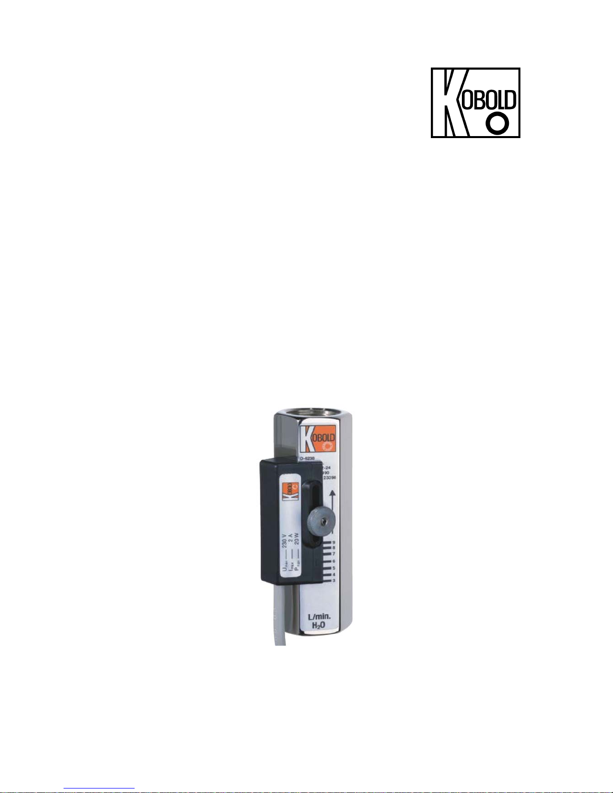
Float Flow Meter / Monitor
Model: SWK
Page 2

SWK
page 2 SWK K06/0618
1. Contents
1. Contents ........................................................................................................ 2
2. Note .............................................................................................................. 3
3. Instrument Inspection .................................................................................... 3
4. Regulation Use .............................................................................................. 4
5. Operating Principle ........................................................................................ 4
6. Use in Hazardous Areas ............................................................................... 5
6.1 General ................................................................................................ 5
6.2 Electrical Contact ................................................................................. 5
6.3 Equipotential Bonding .......................................................................... 5
7. Mechanical Connection ................................................................................. 6
8. Electrical Connection .................................................................................... 6
9. Operation / Configuration / Adjustments ....................................................... 7
9.1 Adjustment of Limit-Value (SWK-1...) .................................................. 7
9.2 Adjustment of Limit-Value (SWK-2...) .................................................. 7
10.Maintenance ................................................................................................. 8
11.Technical Information .................................................................................... 8
12.Order Codes ................................................................................................. 9
13.Dimensions ................................................................................................. 10
14.EU Declaration of Conformance .................................................................. 11
Manufactured and sold by:
Kobold Messring GmbH
Nordring 22-24
D-65719 Hofheim
Tel.: +49(0)6192-2990
Fax: +49(0)6192-23398
E-Mail: [email protected]
Internet: www.kobold.com
Page 3

SWK
SWK K06/0618 page 3
2. Note
Please read these operating instructions before unpacking and putting the unit
into operation. Follow the instructions precisely as described herein.
The devices are only to be used, maintained and serviced by persons familiar
with these operating instructions and in accordance with local regulations
applying to Health & Safety and prevention of accidents.
When used in machines, the measuring unit should be used only when the
machines fulfil the EC-machine guidelines.
as per PED 2014/68/EU
In acc. with Article 4 Paragraph (3), "Sound Engineering Practice", of the
PED 2014/68/EU no CE mark.
Diagram 8, Pipe, Group 1 dangerous fluids
3. Instrument Inspection
Instruments are inspected before shipping and sent out in perfect condition.
Should damage to a device be visible, we recommend a thorough inspection of
the delivery packaging. In case of damage, please inform your parcel service /
forwarding agent immediately, since they are responsible for damages during
transit.
Scope of delivery:
The standard delivery includes:
Float Flow Meter / Monitor Model: SWK
Operating Instructions
Page 4

SWK
page 4 SWK K06/0618
4. Regulation Use
These units, type SWK, are used for the purpose of measuring and monitoring
liquid flow. Only clean, low-viscous and homogeneous liquids may be measured
which do not chemically attack the materials used in the construction of these
units. An attempt to measure high-viscous liquids may lead to considerable
measurement errors.
Large dirt-particles can cause the blockage of float and subsequently turn on
error indications. Also, ferrite particles, which deposit on float (with embedded
magnets), can generate the same effect (we recommend a magnet-filter).
These units are configured in the following manner:
Housing made of Brass, St. Steel or PVC
Attached reed contact N/O with 1m PVC cable (Brass version)
Attached reed contact N/O with 2m PVC cable (PVC/VA version)
Attached and aligned pointer display (option)
5. Operating Principle
KOBOLD Flow Meter/Monitor of type SWK operates according to the well known
float principle, however without making use of the generally employed extended
measuring tube. Inside a cylindrical flow-tube a float with aperture moves in the
direction of the flow against the recoiling force of a spring. Within the float, a pair
of magnets is located which trigger a potential-free protective-gas reed contact
and drives a pointer display. The reed contact is mounted on the exterior of the
flow-housing. The springs arrangement allows the unit to be operated without
consideration to mounting position and keeps the installation dimensions to a
minimum. Flow monitors of type SWK generally find application where small
volume flow needs to be measured in a fail-safe manner.
Page 5

SWK
SWK K06/0618 page 5
6. Use in Hazardous Areas
6.1 General
The Flow Meter/ Monitor does not have a potential igniting source of its own as a
mechanical operating resource; it does not get any identification according to the
guideline 94/9/EC ("ATEX 100a”).
The mounted contact can be used in intrinsically safe circuits as a “simple
apparatus” according to EN 60079-14. The following limit values for the switching
contact should not be exceeded: U = 30 VDC, I = 100 mA, P = 1,2 W.
The measurement units can be used as follows:
a) In the Zone 2 (Gas-Ex, Cat. 3G) into explosion group of IIA, IIB and IIC
b) In the Zone 22 (Dust-Ex, Category 3D) at non-conductive dusts with a
minimum igniting energy of > 3 mJ
c) In the Zone 1 (Gas-Ex, Cat. 2G) into explosion group of IIA, IIB and IIC
d) In the Zone 21 (Dust-Ex, Category 2D) at non-conductive dusts with a
minimum igniting energy of > 3 mJ
6.2 Electrical Contact
In the Ex-area, the Flow Meter/ Monitor can be used according to Category 2G
and 2D for group II; in Zone 1 and 21 in connection with a switching amplifier for
protection type Ex II (2)GD [EEx ia] IIC (intrinsically safe).
The electrical connection is explained in section 8 Electrical Connection.
6.3 Equipotential Bonding
The Flow Meter/ Monitor will allow equipotential bonding of the equipment. This
will occur only when the connection pipes are made of metal.
Page 6
SWK
page 6 SWK K06/0618
7. Mechanical Connection
Before installation:
Make sure that the permitted maximum operating pressure and the operating
temperature of the device are not exceeded.
Make sure that the electrical supply for the devices corresponds with the
operational data of the device.
Make sure that no remains of packing material exist within the device.
The devices should not be installed within an inductive field.
If possible, it should be checked, after the mechanical installation whether the
connection joints/ piping is properly sealed.
Attention! A displacement of switching range occurs if the flow takes
place from top to bottom.
8. Electrical Connection
Attention! Make sure that the voltage values of your system
correspond with the voltage values of the measuring unit, mentioned
on type-label.
Make sure that the supply wires are de-energized.
The connection of the bistable reed contact succeeds is accomplished through
the cable on the contact housing. The potential-free contact closes on rising
level above the adjusted flow value.
Page 7

SWK
SWK K06/0618 page 7
9. Operation / Configuration / Adjustments
The commissioning of these units is prohibited in machines (as long as the
guidelines 89/392/EWG remain enforced), which do not comply with these
guidelines.
The unit is supplied in 'ready for operation' condition. The switching point is
adjusted on the lowest scale value.
9.1 Adjustment of Limit-Value (SWK-1...)
Loosen the knurled nut on the reed contact.
Adjust the marking on the contact for the desired value on the scale. In once
positioned the knurled nut should be tightly screwed.
9.2 Adjustment of Limit-Value (SWK-2...)
Loosen the knurled nut on the reed contact.
Connect a suitable continuity-tester on cable ends.
Case 1: On an installed unit
Open the supply line, and let the flow-medium enter slowly, till the pointer
display shows the desired flow value- at which the rising flow should operate
the switch (the value for the decreasing flow lies below due to the hysteresis).
Case 2: On an uninstalled unit the adjustment may be performed by lifting
the float with a suitable tool.
Switch-housing is repositioned from top to bottom, till the reed contact just
closes (electrical continuity). In this position, secure the contact by tightening
the knurled nut.
The unit is now adjusted and ready for operation.
On correct adjustment, the limit-value contact performs bistable action. That
means, even after on crossing above the adjusted limit-values, the contact
remains closed.
Hysteresis
Hysteresis is an indication of difference between switch-on (rising float) and
switch-off (falling float) points of a contact. The average hysteresis corresponds
to a float-centre movement of about 3 mm.
Page 8
SWK
page 8 SWK K06/0618
10. Maintenance
As long as the medium to be measured is not contaminated, the device SWK is
almost maintenance-free. With lime or such depositions within inner sections
the device should be cleaned regularly.
Attention! Before the commencement of maintenance work, make sure
that the supply wires are de-energized.
11. T echnical Information
Housing/Float: SWK-x1..: brass nickel plated, Ms 58
SWK-x2..: stainless steel, 1.4301
SWK-13..: PVC
Connections: G 1/2 female
Float: SWK-x1..: brass, Ms 58
SWK-x2..: stainless steel, 1.4301
SWK-13..: PVC
Magnets: ceramic
Compression spring: stainless steel 1.4310
Gaskets: none
Butt rings: SWK-x1...: brass, Ms 58
SWK-x2...: stainless steel, 1.4301
SWK-x13...: PVC
Max. temperature: SWK-x1.., SWK-x2: 100 °C
SWK-13..: 60 °C
Max. pressure: SWK-x1.., SWK-x2: 250 bar
SWK-13..: 6 bar
Loss of pressure: 200 mbar at full scale
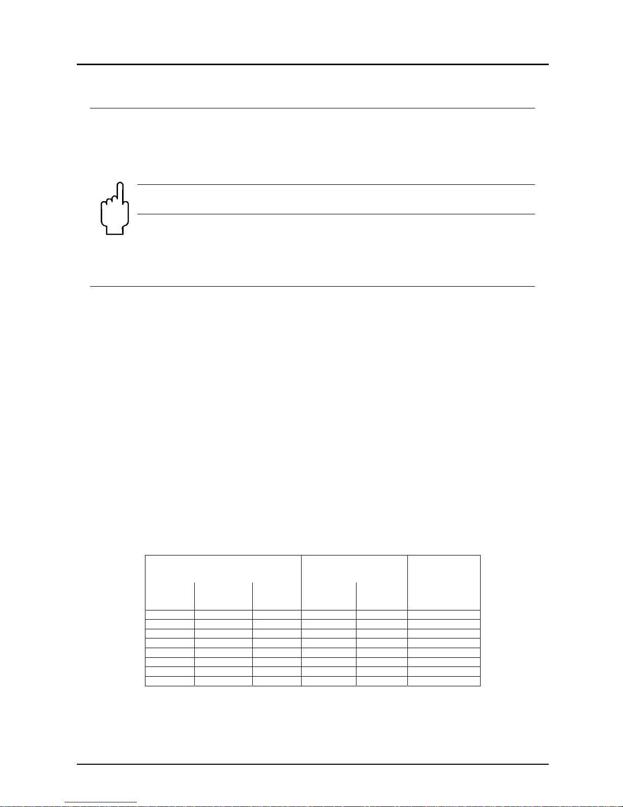
Flow monitors
Flow meters
and monitors
Pressure loss
at f.s.
[mbar]
Material
brass
Material
stainless
steel
Material
PVC
Material
Brass
Material
stainless
steel
SWK 1101 SWK 1201 - SWK 2101 SWK 2201 160
SWK 1102 SWK 1202 - SWK 2102 SWK 2202 180
SWK 1108 SWK 1208 SWK 1308 SWK 2108 SWK 2208 180
SWK 1118 SWK 1218 SWK 1318 SWK 2118 SWK 2218 460
SWK 1140 SWK 1240 SWK 1340 SWK 2140 SWK 2240 330
SWK 1190 SWK 1290 SWK 1390 SWK 2190 SWK 2290 360
SWK 1116 SWK 1216 SWK 1316 SWK 2116 SWK 2216 600
SWK 1124 SWK 1224 SWK 1324 SWK 2124 SWK 2224 490
Page 9
SWK
SWK K06/0618 page 9
Installation position: any position
Switch contact: bistable reed contact
N/O contact or changeover contact with
increasing flow rate
Breaking capacity N/O contact: max. 230 VAC/DC, max. 3 A
max. 60 W/VA
Changeover contact: (SWK-xxxxU)
max. 100 V
AC/DC
, max. 0.5 A, max. 5W/VA
Electr. connection: 1 m PVC cable
Switching hysteresis: 3 mm on scale (mean value)
Repeatability: ≤ 2.5 % (contact)
± 4 % f. s. (indicator)
Protection: IP 68 contact; IP 54 indicator
Ex range: ATEX Zone 1 as “simple apparatus”
Average electrical switch contact life (MTTF):
at max. electrical load: 105 switching operations
at half load (<10%max. load): 5*107 switching operations
at low load (<10V/<1mA): 108 switching operations
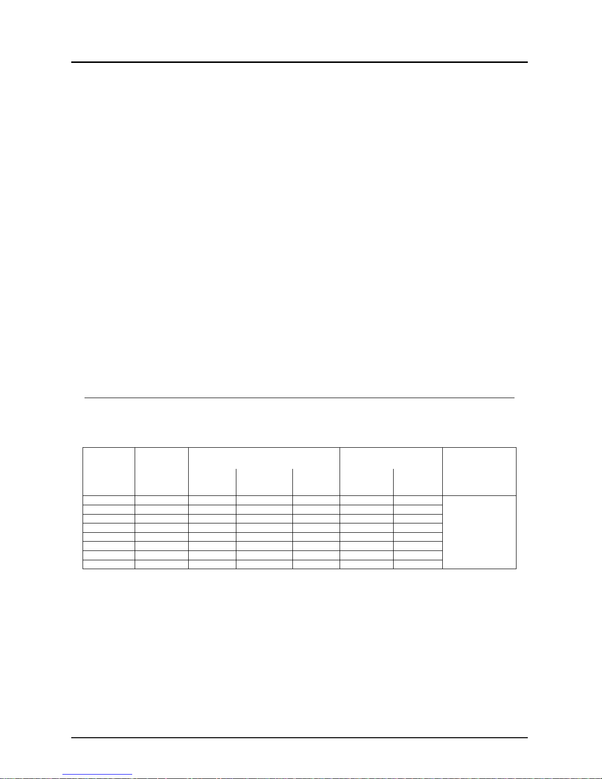
12. Order Codes
Example: SWK-1101
Switching
range
L/min. water
Connection
female
Flow monitors
Flow meters and monitors Switch contact
Material
brass
Material
stainless
steel
Material
PVC
Material
brass
Material
stainless
steel
0.05 - 0.1 G 1/2
SWK 1101 SWK 1201 - SWK 2101 SWK 2201
without = N/O
contact
u = changeover
contact
0.1 - 0.2 G 1/2
SWK 1102 SWK 1202 - SWK 2102 SWK 2202
0.2 - 0.8 G 1/2
SWK 1108 SWK 1208 SWK 1308 SWK 2108 SWK 2208
0.5 - 1.8 G 1/2
SWK 1118 SWK 1218 SWK 1318 SWK 2118 SWK 2218
1.7 - 4.0 G 1/2
SWK 1140 SWK 1240 SWK 1340 SWK 2140 SWK 2240
4.0 - 9.0 G 1/2
SWK 1190 SWK 1290 SWK 1390 SWK 2190 SWK 2290
8 - 16 G 1/2
SWK 1116 SWK 1216 SWK 1316 SWK 2116 SWK 2216
13 - 24 G 1/2
SWK 1124 SWK 1224 SWK 1324 SWK 2124 SWK 2224
Page 10
SWK
page 10 SWK K06/0618
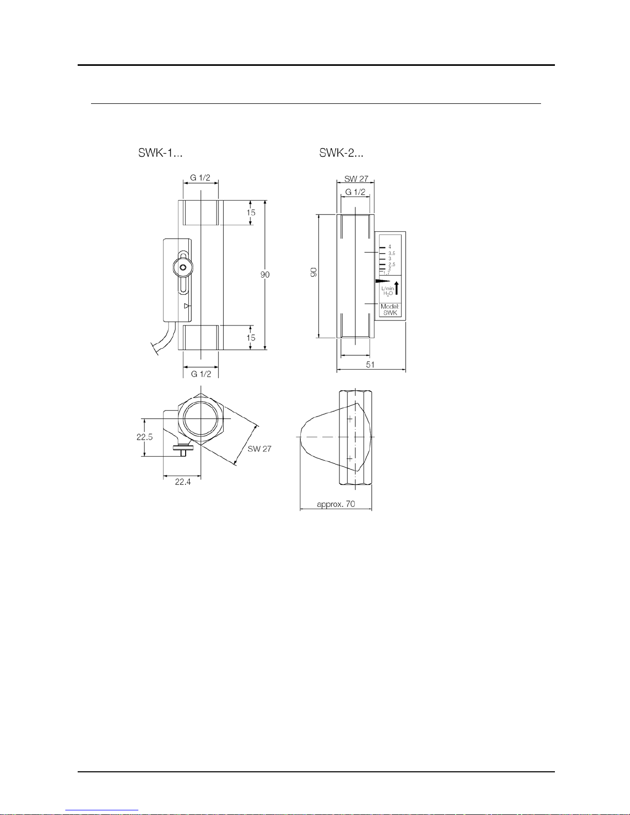
13. Dimensions
Page 11
SWK
SWK K06/0618 page 11
14. EU Declaration of Conformance
We, KOBOLD Messring GmbH, Hofheim-Ts, Germany, declare under our sole
responsibility that the product:
Float Flow Meter / Monitor Model: SWK...
to which this declaration relates is in conformity with the standards noted below:
EN 61010-1:2011
Safety requirements for electrical equipment for measurement, control and
laboratory use
EN 60529:2014
Protection through housing (IP-Code)
Also, the following EC guidelines are satisfied:
2014/35/EU Low Voltage Directive
2011/65/EU RoHS (category 9)
2015/863/EU RoHS
Hofheim, 12. June 2018
H. Peters M. Wenzel
General Manager Proxy Holder
 Loading...