

Kobold SEN-87 Series, SEN-8640 Series, SEN-8600 Series, SEN-8630 Series, SEN-8650 Series Operating Instructions Manual
...Page 1
Operating Instructions
for
Pressure Sensors
Heavy Duty Compact
Model: SEN-86../ SEN-87..
Page 2

SEN-86../87..
page 2 SEN-86../87.. K04/0618
1. Contents
1. Contents ........................................................................................................ 2
2. Note .............................................................................................................. 3
3. Instrument Inspection .................................................................................... 3
4. Regulation Use .............................................................................................. 3
5. Operating Principle ........................................................................................ 4
6. Mechanical Connection and Putting to Operation ......................................... 4
7. Electrical Connection .................................................................................... 5
8. Maintenance ................................................................................................. 7
9. Trouble shouting ........................................................................................... 7
10.Technical Information .................................................................................... 8
11.Order Codes ................................................................................................. 9
12.Dimensions ................................................................................................. 11
13.EU Declaration of Conformance .................................................................. 12
Manufactured and sold by:
Kobold Messring GmbH
Nordring 22-24
D-65719 Hofheim
Tel.: +49(0)6192-2990
Fax: +49(0)6192-23398
E-Mail: info.de@kobold.com
Internet: www.kobold.com
Page 3

SEN-86../87..
SEN-86../87.. K04/0618 page 3
2. Note
Please read these operating instructions before unpacking and putting the unit
into operation. Follow the instructions precisely as described herein.
The devices are only to be used, maintained and serviced by persons familiar
with these operating instructions and in accordance with local regulations applying to Health & Safety and prevention of accidents.
When used in machines, the measuring unit should be used only when the
machines fulfil the EC-machine guidelines.
3. Instrument Inspection
Instruments are inspected before shipping and sent out in perfect condition.
Should damage to a device be visible, we recommend a thorough inspection of
the delivery packaging. In case of damage, please inform your parcel service /
forwarding agent immediately, since they are responsible for damages during
transit.
Scope of delivery:
The standard delivery includes:
Pressure Sensors Heavy Duty Compact model: SEN-86../87..
Operating Instructions
4. Regulation Use
Pressure sensors transmit the mechanical pressure signal into an electrical
output signal. The media’s which are in contact with the instrument should have
no effects on the instrument materials used. Do not use standard units in
hazardous areas and for oxygen applications.
Page 4
SEN-86../87..
page 4 SEN-86../87.. K04/0618
G 1/2 A
R 16
z
* min.
S
ealing acc. DIN 16288 Sealing with flat gasket
7
+0,2
G 1/2 A
R 16
z
* min.
7
+0,2
21,3
-0,2
G 1/4 A
R 16
z
* min.
7
20,5
14,5
14,5
19
24,5
24,5
13
16,5
9
+0,2
- 0,5
- 0,5
- 0,5
+1
+1
+1
5. Operating Principle
KOBOLD Pressure sensors model SEN-86 are inexpensive pressure sensors
with thick film ceramic pressure element. With their accuracy, reliability and
compact design, they are perfectly suitable for OEM applications in medium to
high quantities.
The materials and technology used make these pressure sensors insensitive to
chemically aggressive media and mechanical load.
Particularly hydraulics systems with their high and fast pressure peaks are thus
preferred applications.
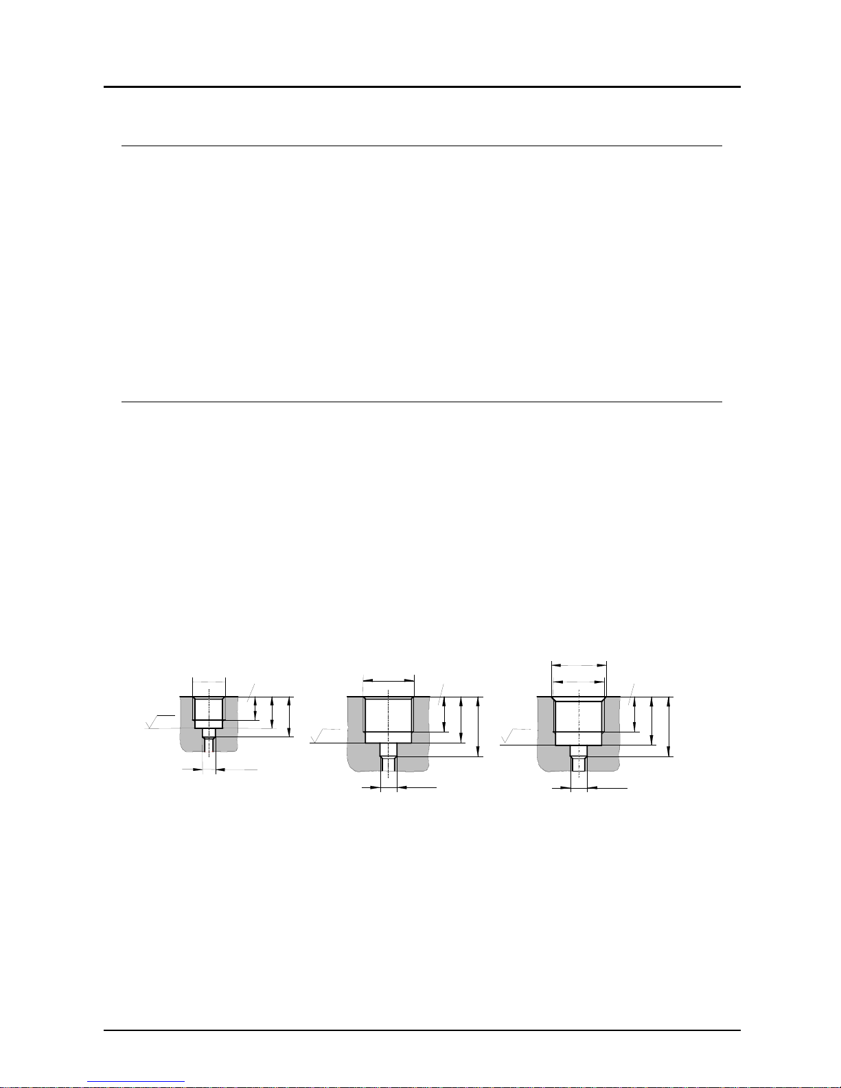
6. Mechanical Connection and Putting to Operation
The place where pressure is taken should be prepared according the following
specifications for the screw-in threads.
For sealing, please use sealing discs acc. DIN 16258 or profile washers. The
maximum initial tension depends on the material, the shape of the used sealing
and the mechanical connection of the pressure sensor.
There should be no vibrations and/or no radiation of heat near the mounting
position of the sensors. Please pay attention that the given technical data’s are
not exceeded. After the mechanical and electrical connection the sensor works
immediately.
Page 5

SEN-86../87..
SEN-86../87.. K04/0618 page 5
7. Electrical Connection
Ensure that the power is disconnected during connection of the cable.
The electrical connection is made either via plug and pin or by cable.
The exact wiring scheme is shown on the sketches hereafter or at the type
plate of your sensor.
Meaning of the different connector markings
UB+ positive pole of the supply voltage
OV negative pole of the supply voltage
S+ positive pole of the output signal
S- negative pole of the output signal
Shielding Cable protection enclosure-earth
The sensor can be supplied with a non stabilised DC source with the given voltage range. The minimum supply voltage for pressure sensors with current output
should be the minimum UB plus the minimum voltage, which is needed for the
external indicator:
Current output
2-wire system 3-wire system
Output signal 4...20 mA 0...20 mA
Supply voltage UB= 15 ... 32 VDC
Permissible load RA[Ohm] = (UB[V] - 15 V) / 0,02 A
Wiring see schematic
Voltage output
3-wire system 3-wire system
Output signal 0...5 V 0...10 V
Supply voltage UB= 15 ... 32 VDC
Permissible load
R
A >5 k RA >10 k
Wiring see schematic
Page 6

SEN-86../87..
page 6 SEN-86../87.. K04/0618
Electrical connection, principle drawings
pin assignment, cable marking
0V/S-
0V/S-
U
B
+
U
B
+
U
B
+/S+
U
B
+/S+
Supply
U
B
(DC)
Supply
U
B
(DC)
Supply
U
B
(DC)
Supply
U
B
(DC)
Supply
UB (DC)
Supply
U
B
(DC)
Indicator Indicator
Indicator
Indicator
Indicator
Indicator
1
2
3
green 0V/S-
green
0V/S-
white S+
DIN 43650 plug
5 - pin plug (Binder)
With free cable
brown U
B
+blue UB+
0V/S-
S+
3
2
1
5
4
3
2
1
5
4
S+
1
2
3
shielding
shilding
2-wire-system
3-wire-system
2-wire-system 3-wire-system
Attention! Incorrect wiring will lead to damage of the unit’s electronics.
Page 7

SEN-86../87..
SEN-86../87.. K04/0618 page 7
8. Maintenance
The pressure sensors described in this manual are maintenance free! They do
not contain any components which may be repaired or exchanged locally.
Repairs are not possible other than in our factory.
9. Trouble shouting
Trouble Possible reason What's to do
No signal no supply voltage
broken wire
Check your power supply and
wiring. lf necessary replace
defective parts
Sensor has been wired faulty Check the wiring according to
the sketches, adjust wiring if
necessary.
No pressure Check your tubing , valves
open?
Defective electronics
caused by to high supply
voltage or by external voltage
Return sensor to us for repair
Unchanged signal by Pressure port is clocked Clean the pressure port
changing pressure Defective electronic caused
by to high supply voltage or
by external voltage
Return sensor to us for repair
Pressure sensor over pressurized
Return sensor to us for repair
To high, even on changing
pressure unchanged signal
Defective electronics caused
by to high supply voltage or
by external voltage
Return sensor to us for repair
Span of signal to small Supply voltage to low
Resistance to high
Adjust supply voltage Adhere
to max. allowable resistance
Zero signal to high Mechanical overburden Return to us for repair
Output signal non linear Mechanical overburden Recalibrate sensor resp. re-
turn to us for repair
Page 8

SEN-86../87..
page 8 SEN-86../87.. K04/0618
10. T echnical Information
Model
SEN-86x0 SEN -87x0
Technology internal diaphragm
Pressure type gauge pressure
Housing stainless steel 1.4305
Connection:
G ½ male; stainless steel
1.4301 (NPT, UNF on
request)
G ¼ male; stainless steel
1.4301 (NPT, UNF on
request)
Sensor element ceramic (Al2O3)
Measuring principle thick film techn. (DMS)
O-Ring NBR
Max. Temperature
Storage: -30...+100 °C
Medium: -20...+125 °C
Ambient: -30...+100 °C
Storage: -30...+100 °C
Medium: -20...+ 85 °C
Ambient: -30...+100 °C
Pressure limitation
< 60 bar: 2 x range
≥ 60 bar: 1.5 x range
Accuracy class 0.5 f.s.d.)
Repeatability
± 0.15 % (f.s.d.)
Characteristic deviation
± 0.3 % (f.s.d.)
Stability (annual)
± 0.2 % of full scale
in rated conditions
Electrical connection
Plug DIN 43 650 A / Plug M12x1
Cable connection
Power supply 15...32 VDC
Output signal 4 – 20 mA, (2-wire), 0 – 10 VDC
Load () (UB – 15 V)/0.02 A (for 4 – 20 mA)
Response time
1 ms (within 10 – 90% of full scale)
Temp. comp. range -25...+85 °C
Temperature drift Zero:
± 0.02% full scale/K
Measuring span:
± 0.01% full scale/K
Protection
IP 65 (SEN-860..; SEN-863..)
IP 68 (SEN-865..)
Options Absolute pressure for ranges 1.0...25 bar
Oil- and free of grease for oxygen
Silicone- and LABS free
Connection with 50 mm cooling fins t
max
125 °C
Connection and housing SS 1.4539
1)
instead of 1.4305
Connection and housing SS 1.4571 instead of 1.4305
O-ring FPM instead of NBR
O ring PTFE (Kalrez) instead of NBR <100 bar
½” NPT thread instead of “G”
G¼ DIN385-E inclusive seal
ring
3)
Special connection2) on request
1)
Seawater resistant
2)
Please specify in writing
3)
Adapter of PSD usable
Page 9

SEN-86../87..
SEN-86../87.. K04/0618 page 9
11. Order Codes
Sensor (Example: SEN-8600 C315)
Electrical
connection
Class Model Output Measuring range Options
DIN-plug;
IP 65
0.5
SEN-8600..
without =
4 – 20 mA
/2 = 0 –10 V
C305 = -0.6...0 bar
C315= -1 ...0 bar
C505 = -1...0.6 bar
C515 = -1…1.5 bar
C525 = -1…3 bar
C535 = -1…5 bar
C545 = -1…9 bar
C555 = -1...15 bar
B015 = 0…0.6 bar
B025= 0...1 bar
B035= 0…1.6 bar
B045= 0…2.5 bar
B055= 0…4 bar
B065= 0…6 bar
B075= 0…10 bar
B085= 0...16 bar
A095= 0...25 bar
A105= 0...40 bar
A115= 0...60 bar
A125= 0...100 bar
A135= 0...160 bar
A140 = 0...200 bar
A145= 0...250 bar
A155= 0...400 bar
A165 = 0...600 bar
A170 = 0...700 bar
A175 = 0...800 bar
H 315= -30...0 Hg
P 020 = 0...10 psi g
P 025= 0...15 psi g
P 045= 0...30 psi g
P 055= 0...50 psi g
P 060 = 0...60 psi g
P 065= 0...100 psi g
P 075= 0...150 psi g
P 085= 0...200 psi g
P 090 = 0...300 psi g
P 095= 0...350 psi g
P 100 = 0...500 psi g
P 105= 0...600 psi g
P 115= 0...1000 psi g
P 125= 0...1450 psi g
P 130 = 0...2000 psi g
P 135= 0...2300 psi g
P 140 = 0...300 psi g
P 145= 0...3600 psi g
P 150 = 0...500 psi g
P 155= 0…5800 psi g
P 160 = 0…7500 psi g
P 165 = 0…10000 psi g
YYY= special range,
please specify in
writing
Thread
without = G ½ male
Y = absolute
pressure for
ranges
1.0…25 bar
Y = oil- and free of
grease for
oxygen
Y = silicone- and
LABS-free
Y = connection with
50 mm cooling
fins t
max
125 °C
Y = connection and
housing SS
1.4539 (seewater
resistant) instead
of 1.4305
Y = connection and
housing SS
1.4571 instead
of 1.4305
Y = O-ring FPM
instead of NBR
Y = O-ring PTFE
(Kalrez) instead of
NBR <100 bar
Y = special
connection on
request, please
specify in writing
N = ½” NPT male
M12-plug;
IP 67
0.5
SEN-8630..
Cable connection;
IP67
Standard cable 1 m
(other length on
request)
SEN-8640..
Cable connection;
IP 68
Standard cable 1 m
(other length on
request)
0.5
SEN-8650..
Page 10

SEN-86../87..
page 10 SEN-86../87.. K04/0618
Sensor (Example: SEN-8700 C315)
1)
Seawater resistant
2)
Please specify in writing
3)
Adapter of PSD usable
Electrical
connection
Class Model Output
Measuring
range
Options
DIN-plug;
IP 65
0.5
SEN-8700..
without =
4 – 20 mA
/2 = 0 –10 V
C305 = -0.6...0 bar
C315= -1 ...0 bar
C505 = -1...0.6 bar
C515 = -1…1.5 bar
C525 = -1…3 bar
C535 = -1…5 bar
C545 = -1…9 bar
C555 = -1...15 bar
B015 = 0…0.6 bar
B025= 0...1 bar
B035= 0…1.6 bar
B045= 0…2.5 bar
B055= 0…4 bar
B065= 0…6 bar
B075= 0…10 bar
B085= 0...16 bar
A095= 0...25 bar
A105= 0...40 bar
A115= 0...60 bar
A125= 0...100 bar
A135= 0...160 bar
A140 = 0...200 bar
A145= 0...250 bar
A155= 0...400 bar
A165 = 0...600 bar
A170 = 0...700 bar
A175 = 0...800 bar
H 315= -30...0 Hg
P 020 = 0...10 psi g
P 025= 0...15 psi g
P 045= 0...30 psi g
P 055= 0...50 psi g
P 060 = 0...60 psi g
P 065= 0...100 psi g
P 075= 0...150 psi g
P 085= 0...200 psi g
P 090 = 0...300 psi g
P 095= 0...350 psi g
P 100 = 0...500 psi g
P 105= 0...600 psi g
P 115= 0...1000 psi g
P 125= 0...1450 psi g
P 130 = 0...2000 psi g
P 135= 0...2300 psi g
P 140 = 0...300 psi g
P 145= 0...3600 psi g
P 150 = 0...500 psi g
P 155= 0…5800 psi g
P 160 = 0…7500 psi g
P 165 = 0…10000 psi g
YYY= special range,
please specify in
writing
Thread
without = G ¼ male
Y = absolute
pressure for
ranges
1.0…25 bar
Y = oil- and free of
grease for
oxygen
Y = silicone- and
LABS-free
Y = connection with
50 mm cooling
fins t
max
125 °C
Y = connection and
housing SS
1.4539
1)
(seewater
resistant) instead
of 1.4305
Y = connection and
housing SS
1.4571 instead
of 1.4305
Y = O-ring FPM
instead of NBR
Y = O-ring PTFE
(Kalrez) instead of
NBR <100 bar
Y = G ¼ DIN 385-E
inclusive seal ring
Y = special
3)
connection
2)
on
request, please
specify in writing
N = ½” NPT male
M12-plug;
IP 67
0.5
SEN-8730..
Cable
connection; IP67
Standard cable
1 m (other length
on request)
0.5
SEN-8740...
Cable
connection;
IP 68
0.5
SEN-8750..
Page 11

SEN-86../87..
SEN-86../87.. K04/0618 page 11
12. Dimensions
[in mm]
SEN-86
SEN-87
Page 12

SEN-86../87..
page 12 SEN-86../87.. K04/0618
13. EU Declaration of Conformance
We, KOBOLD-Messring GmbH, Hofheim-Ts, Germany, declare under our sole
responsibility that the products:
Pressure Sensors models: SEN-86... and SEN-87...
to which this declaration relates in conformity with the standards noted below:
EN 61326-1:2013 Electrical equipment for measurement, control and
laboratory use - EMC requirements - Part 1: General requirements
EN 61326-2-3:2013 Electrical equipment for measurement, control and
laboratory use - EMC requirements - Part 2-3: Particular requirements - Test
configuration, operational conditions and performance criteria for transducers
with integrated or remote signal conditioning
EN 50581:2012 Technical documentation for the assessment of electrical
and electronic products with respect to the restriction of hazardous substances
Also the following EC guidelines are fulfilled:
2014/30/EU EMC Directive
2014/68/EU PED
PS200 bar; module A, pressure accessory
2011/65/EU RoHS (category 9)
Hofheim, 23. Jan. 2018
H. Peters M. Wenzel
General Manager Proxy Holder
 Loading...