

Page 1
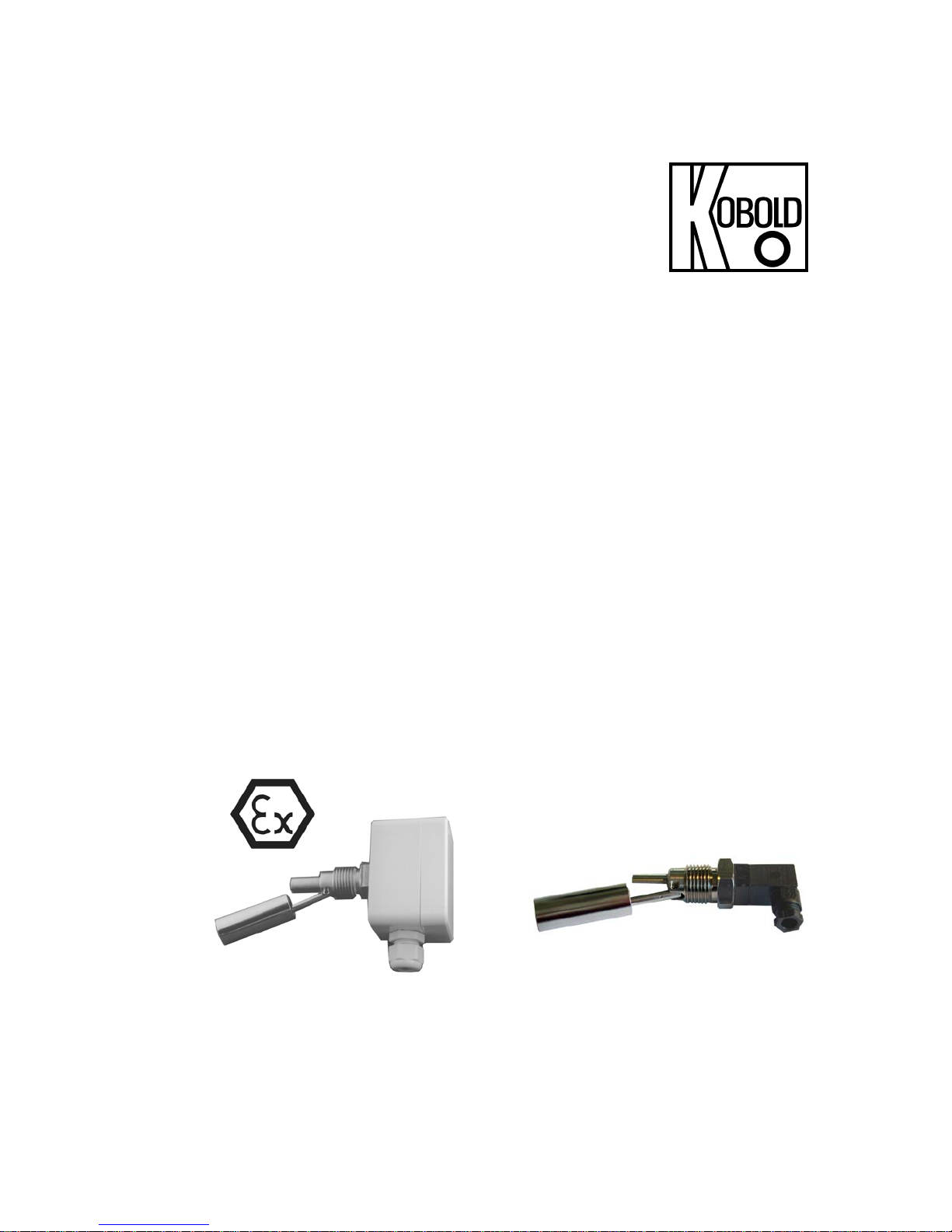
Operating Instructions
for
Level Switch for Liquids
Model: RFS
Page 2

RFS
page 2 RFS K02/0118
1. Contents
1. Contents ........................................................................................................ 2
2. Note .............................................................................................................. 3
3. Instrument Inspection .................................................................................... 3
4. Regulation Use .............................................................................................. 3
5. Operating Principle ........................................................................................ 4
6. Use in Hazardous Areas ............................................................................... 4
7. Mechanical Connection ................................................................................. 5
8. Electrical Connection .................................................................................... 6
9. Technical Information .................................................................................... 8
10.Order Codes ................................................................................................. 9
11.Dimensions ................................................................................................. 10
12.EU Declaration of Conformance .................................................................. 11
13.ATEX-Certificate ......................................................................................... 12
Manufactured and sold by:
Kobold Messring GmbH
Nordring 22-24
D-65719 Hofheim
Tel.: +49(0)6192-2990
Fax: +49(0)6192-23398
E-Mail: info.de@kobold.com
Internet: www.kobold.com
Page 3

RFS
RFS K02/0118 page 3
2. Note
Please read these operating instructions before unpacking and putting the unit
into operation. Follow the instructions precisely as described herein.
The devices are only to be used, maintained and serviced by persons familiar
with these operating instructions and in accordance with local regulations
applying to Health & Safety and prevention of accidents.
When used in machines, the measuring unit should be used only when the
machines fulfil the EC-machine guidelines.
3. Instrument Inspection
Instruments are inspected before shipping and sent out in perfect condition.
Should damage to a device be visible, we recommend a thorough inspection of
the delivery packaging. In case of damage, please inform your parcel service /
forwarding agent immediately, since they are responsible for damages during
transit.
Scope of delivery:
The standard delivery includes:
Level Switch model: RFS
Operating Instructions
4. Regulation Use
Model RFS devices are used for when monitoring liquid levels. The device should
only be used with liquids that are compatible with the unit’s materials of
construction.
Level control is often accomplished with at least two level switches - one acting to
sense the minimum level and the other for maximum level detection.
Any use of the Level Switch, model: RFS, which exceeds the manufacturer’s
specification, may invalidate its warranty. Therefore, any resulting damage is not
the responsibility of the manufacturer. The user assumes all risk for such usage.
Page 4
RFS
page 4 RFS K02/0118
5. Operating Principle
The Level Switch RFS is designed for economical control of liquids in vessels.
The following three versions are available: A device with plug connection and two
devices with aluminium housing connection of which one is an ATEX-version for
the use in environment with gas explosion hazards. The switch is remarkable for
its maintenance-free design and small dimensions. The switch is mounted on the
side of the vessel. A hinged stainless steel float with a magnet floats up and down
through the liquid level. In the end position a potential-free reed contact is
operated by the magnet. The switching function (N/O contact / N/C contact) is
determined by the mounting position. The switching function is reserved by
simply rotating the switch through 180°.
6. Use in Hazardous Areas
With the approval the Level Switch, model RFS, can be used within hazardous
areas. Thereby the aluminium housing is applicable outside the process in zone
of category 2D. The float is appropriate for the use within the process in zone of
category 2D and 1D.
The approvals are as follows:
II 1 GD Ex ia IIC T6 Ga
-20≤Ta≤+60 °C
An additional intrinsically safe relay is required in environment with gas explosion
hazards (KFA…and respectively KFD).
For a correct and professional potential equalization, the ground terminal on the
housing of the RFS must be connected in applications in hazardous areas.
Page 5
RFS
RFS K02/0118 page 5
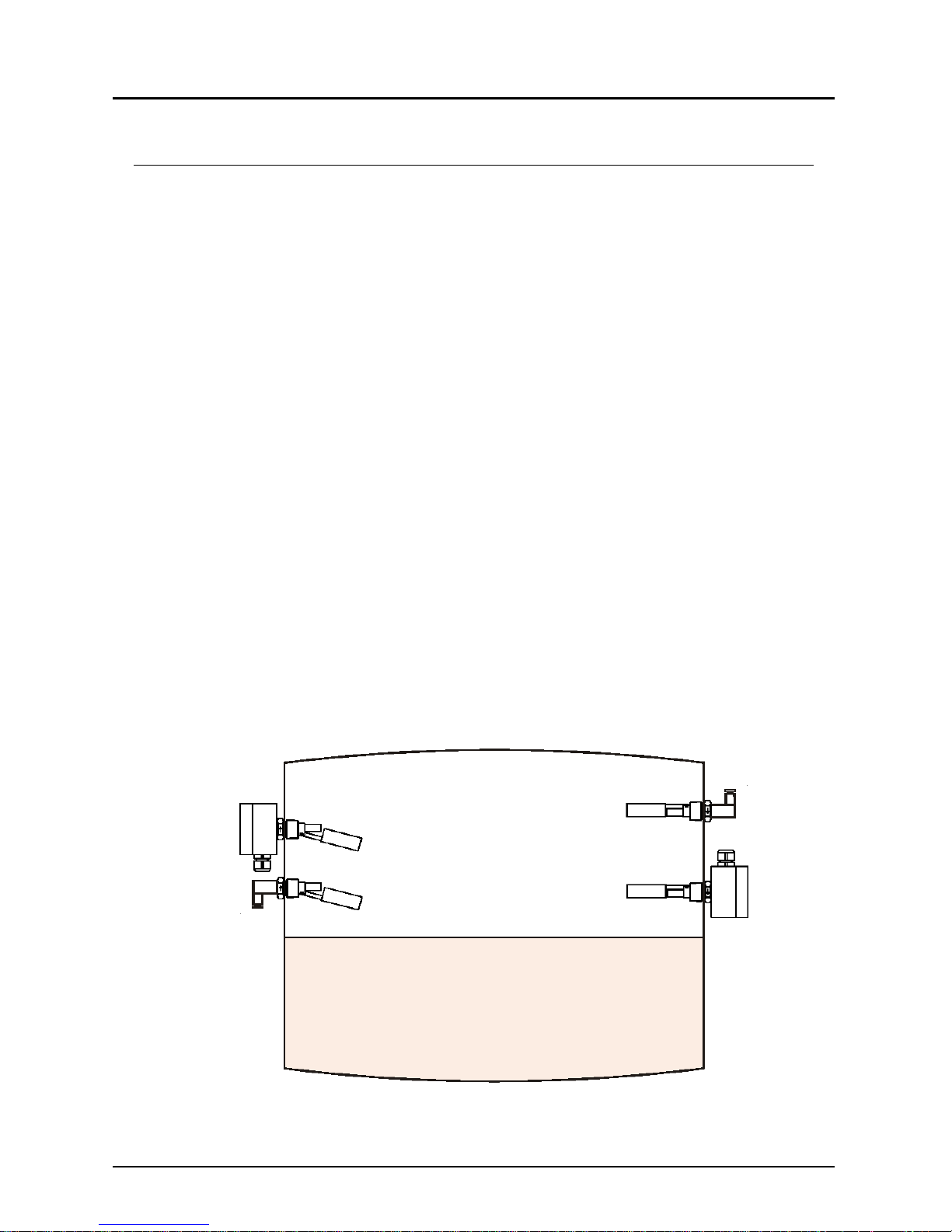
7. Mechanical Connection
The Level Switch should be mounted so that the float can move freely over its
entire path without hitting the walls, floor or roof of the container. Avoid fitting the
switch where agitators or inlet valves could expose it to excessive turbulence.
Make sure that the medium does not contain solids or ferrite particles, as they
could collect on the float magnet and interfere with the switching operation. If the
liquid does contain sediment or suspended matter, you must be sure they do not
come into contact with the float system.
Mount the switch in a way that it is easily accessible for installation and
maintenance.
Make sure that the allowed max. operational pressure and service temperature
for the device is not exceeded.
The installation position must be horizontal.
If possible, examine all the connection joints for proper sealing, just after
mechanical installation.
The engraved arrow on the hexagon must point up or down depending on the
desired contact function. In any case the marked hexagon surface must always
be mounted vertically.
Mounting position
Depending on the mounting position of the device, the contact function (N/O or
N/C contact) of the level switch will be defined.
Mounted as
N/O contact
Mounted
as N/C
Page 6
RFS
page 6 RFS K02/0118
8. Electrical Connection
Caution! Make sure that the voltage values of your system
correspond with the voltage values of the level switch.
Make sure that the supply wires are de-energised.
Connect your connection cable to the terminal of the aluminium housing or the
plug of the RFS level switch.
The level switch has a protective insulation; a separate protection wiring for the
standard version is not necessary.
For the RFS version for ATEX applications, the connection of the potential
terminal is mandatory.
An additional intrinsically safe relay is required in environment with gas
explosion hazards (KFA…and respectively KFD).
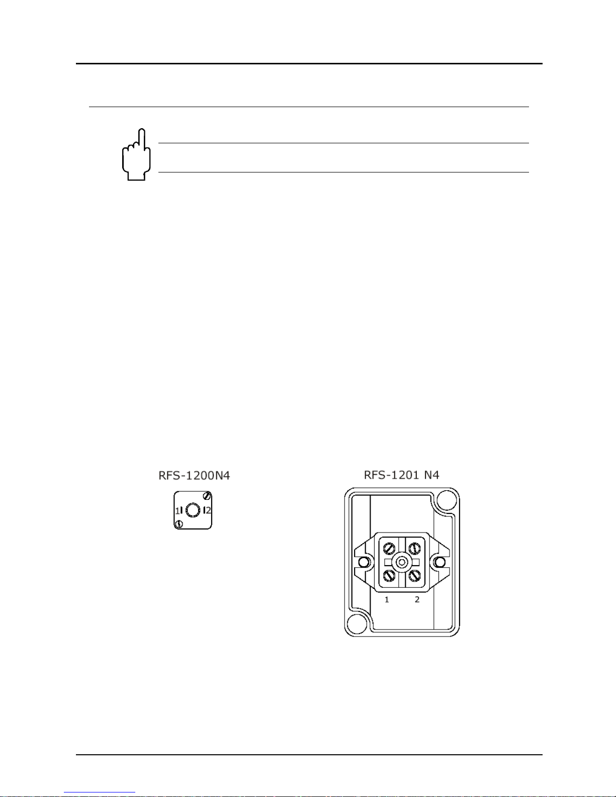
Pin assignment for RFS Level Switch
RFS-1200N4 and RFS-1201N4
There are only two connection terminals which can be connected by choice and
which do not have any influence on the contact function (N/C / N/O). The contact
function is defined by the mounting position of the instrument.
Page 7

RFS
RFS K02/0118 page 7
RFS-12EXN4
There are three connection terminals of which one terminal is clearly marked as a
ground terminal. The two other terminals are connected in the same way as the
standard devices RFS-1200N4 and RFS-1201N4 respectively.
After the connection of any other from your designated external instruments to
the limit contact, the device is ready for operation.
Page 8

RFS
page 8 RFS K02/0118
9. Technical Information
Medium temperature: - 40...+120 °C
Ambient temperature: -20...+80 °C
(RFS-1200 N4 and RFS-1201 N4)
-20...+ 60 °C
(RFS-12Ex N4)
Operating pressure: max. 5 bar
mounting position: horizontal
Materials
• Housing / plug: plastic with RFS-1200 N4
aluminium with RFS-1201 N4
and RFS-12Ex N4
• Float: stainless steel 1.4301
• Connection: stainless steel 1.4301
Process connection: 1/2 NPT
Electr. connection: for RFS-1200 N4: DIN plug
for RFS-1201 and RFS-12Ex:
terminals in the aluminium connection
Contacts: N/O or N/C contact,
depending on the mounting
position of the device
Switching voltage: max. 240 V
AC / 300 VDC
with RFS-1200 and RFS-1201
max. 40 VDC with RFS-12Ex
Switching current: max. 0.5 A
Switching capacity: max. 15 VA
with RFS-1200 and RFS-1201
max. 4 VA with RFS-12Ex
Medium density: >0.7 g/cm
3
Contact resistance: max. 150 kΩ
Protection: IP65
ATEX marking
for RFS-12Ex: II 1 GD Exia IIC T6 Ga
-20°C ≤ Ta ≤ +60 °C
Page 9

RFS
RFS K02/0118 page 9
10. Order Codes
Example: RFS-1200 N4
Model Description
RFS-1200 N4
Standard version with
plug connection
RFS-1201 N4
Standard version with
housing connection
(aluminium)
RFS-12Ex N4*
ATEX version for use in
environments with explosion
hazards
*an additional relay is required for the use
in environment with gas explosion hazards
Page 10

RFS
page 10 RFS K02/0118
11. Dimensions
RFS-1201 N4, RFS-12Ex N4
4719.5
8
.5
17.5
1/2 NPT
2
8
1
7
50
65
M16
RFS-1200 N4
4719.5
8
.5
17.5
1/2 NPT
2
8
1
7
Page 11

RFS
RFS K02/0118 page 11
12. EU Declaration of Conformance
DECLARACIÓN DE CONFORMIDAD EU
EU DECLARATION OF CONFORMITY
EU-KONFORMITÄTSERKLÄRUNG
DÉCLARATION DE CONFORMITÉ
DICHIARAZIONE DI CONFORMITÀ EU
KOBOLD MESURA SLU
Avda. Conflent 68 nave 15 08915 Badalona (España)
Declara, bajo la propia responsabilidad, que el producto
Declares under our sole responsibility, that the product
Erklärt in alleiniger Verantwortung, dass das Produkt
Déclare sous sa seule responsabilité, que le produit
Dichiara sotto la propia responsabilità, che il prodotto
Magnetic level switch
RFS-12Ex N4
A los cuales se refiere esta declaración, son conformes a las siguiente Directivas Europeas:
To which this declaration relates is in conformity with the following European Directives:
Mit folgenden Euroäischen Richtlinien Konform ist:
À auxquels se réfère cette déclaration, ils sont conformes aux Directives Européennes suivant :
A ai quali si riferisce questa dichiarazione, sono conformi alle direttive europee seguente:
EMC2014/30/EU LVD2014/35/EU ATEX2014/34/EU RoHS2011/65/EU
Normas armonizadas y documentos de la normativa aplicados:
Applied harmonised standards and normative documents:
Angewandte harmonisierte Normen und normative Dokumente:
Normes harmonisées et documents normatifs appliqués
Norme armonizzate e documenti normativi applicati:
EN61010-1 :2011 EN60079-0:2012 (acc. EN60079-0:2013)
EN61000-6-2 :2006 EN60079-11:2012 (acc. EN60079-11:2013)
Certificado de examen CE de tipo Marcado
EC-type examination certificate Marking
EG-baumusterprüfbescheinigung Kennzeichnung
Attestation d´examen CE de type Inscription
Certificazione per esame di tipo CE Marcatura
LOM06ATEX2054X
II 1 GD Ex ia IIC T6 Ga
-20≤Ta≤+60ºC
Fabricado en: KOBOLD MESURA SLU Avda. Conflent 68 nave 15 08915 BADALONA (Spain)
Made in:
Hergestellt in:
Fabriqué dans:
Fabbricato in:
Organismo notificado
: LOM 0163 Número notificación : LOM 05ATEX9070
Notified organism Notification number
Zertifizierungsstelle Zertifikatsnummer
Organization annoncée Nombre notification
Organismo informato Notifica di numero
Badalona april. 2016
DT0497
Gerente
Page 12

RFS
page 12 RFS K02/0118
13. A TEX-Certificate
Page 13

RFS
RFS K02/0118 page 13
Page 14

RFS
page 14 RFS K02/0118
Page 15

RFS
RFS K02/0118 page 15
Page 16

RFS
page 16 RFS K02/0118
Page 17

RFS
RFS K02/0118 page 17
Page 18

RFS
page 18 RFS K02/0118
 Loading...