

Page 1
Operating Instructions
for
Flow Restrictors
Model: REG
Page 2

REG
1. Contents
1. Contents ........................................................................................................ 2
2. Note .............................................................................................................. 3
3. Instrument Inspection .................................................................................... 3
4. Regulation Use .............................................................................................. 3
5. Operating Principle ........................................................................................ 4
6. Mechanical Connection ................................................................................. 4
7. Technical Information .................................................................................... 5
8. Differential Pressure Curve ........................................................................... 5
9. Dimensions and Order Codes ....................................................................... 6
Manufactured and sold by:
Kobold Messring GmbH
Nordring 22-24
D-65719 Hofheim
Tel.: +49 (0)6192-2990
Fax: +49(0)6192-23398
E-Mail: info.de@kobold.com
Internet: www.kobold.com
page 2 REG K05/1115
Page 3

REG
2. Note
Please read these operating instructions before unpacking and putting the unit
into operation. Follow the instructions precisely as described herein.
The devices are only to be used, maintained and serviced by persons familiar
with these operating instructions and in accordance with local regulations
applying to Health & Safety and prevention of accidents.
When used in machines, the measuring unit should be used only when the
machines fulfil the EC-machine guidelines.
as per PED 2014/68/EU
In acc. with Article 4 Paragraph (3), "Sound Engineering Practice", of the
PED 2014/68/EU no CE mark.
Diagram 8, Pipe, Group 1 dangerous fluids
3. Instrument Inspection
All instruments are inspected before shipping and sent out in perfect condition.
Should damage to a device be visible, we recommend a thorough inspection of
the delivery packaging. In case of damage, please inform your parcel service /
forwarding agent immediately, since they are responsible for damages during
transit.
Scope of delivery:
The standard delivery includes:
Flow Restrictors model: REG
Operating Instructions
4. Regulation Use
Any use of the Flow Restrictor, model: REG, which exceeds the manufacturers
specification may invalidate its warranty. Therefore, any resulting damage is not
the responsibility of the manufacturer. The user assumes all risk for such usage.
REG K05/1115 page 3
Page 4

REG
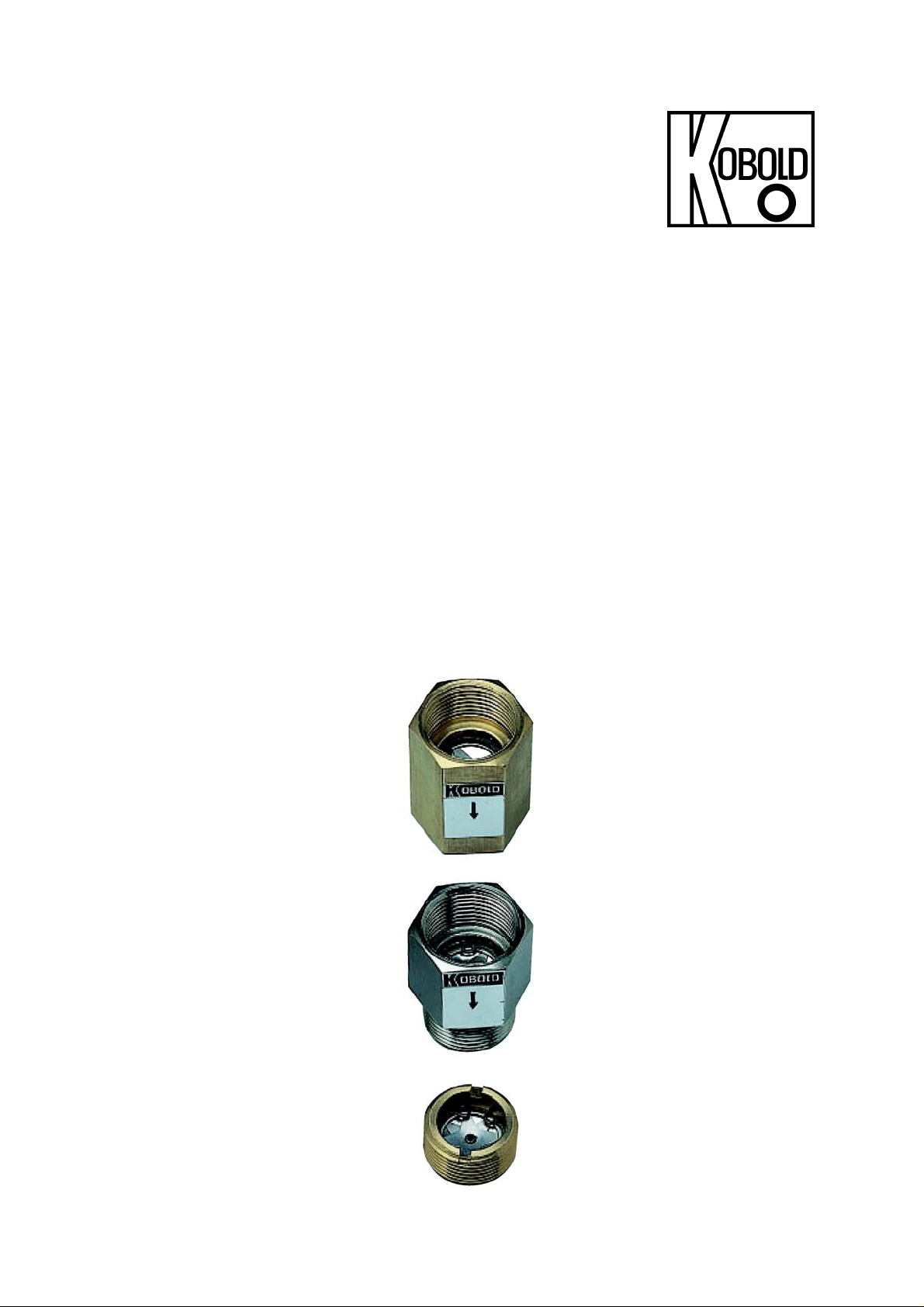
5. Operating Principle
KOBOLD model REG flow restrictors serve to keep constant quantities of liquids
in pipework systems. The REG rate regulators are ideally suited for the simple
restriction of a preset value of throughputs of water or of liquids similar to water.
The flow restrictors ensure an equilibrium, particularly in systems with many
consumers and resulting pressure fluctuations caused by random flow conditions.
In other words, the desired throughput is not exceeded.
Constant flow is achieved by two stainless steel spring plates that are crosswise
mounted and riveted together. The gap between the spring-loaded stainless steel
plate and the seal-surface is continuously varied as the differential pressure
changes. As the differential pressure decreases, the gap widens, and it closes as
the pressure increases, thus maintaining a constant flow volume through the
device.
6. Mechanical Connection
Before installation:
Remove all transport securing devices and make sure that there are no more
packaging parts left in the device.
Make sure that the permitted maximum operating pressures and temperatures
for the device are not exceeded (see 7 Technical Information)
Install the flow limiter into the piping without mechanical stress.
Protect the measuring pipe against external damage.
Avoid pressure surges in the measuring pipe e.g. by blocking the flow quickly.
If possible, after mechanical installation, make sure that the connection
between screw connection and pipe is tight and does not leak.
Maximum tightening torques for process connection:
G ½ 30 Nm
G ¾ 30 Nm
G1 38 Nm
Warning! The differential pressure must not exceed 10 bar.
page 4 REG K05/1115
Page 5

REG
7. Technical Information
Connections: female thread G ½, G ¾
female/male thread G 1/2-G ¾
male thread G ¾
female thread ¾ NPT
female/male thread ¾ NPT
multiple element
male thread
G 1 ½, G 2, G 2 ¼, G 2 ½
Flange DN 20/25/32/40/50/65/80/100
Service temperature: -10...+300 °C
Operating pressure: max. 200 bar
Allowable operating
pressure REG-82Fx: see order details, page 11, table
Differential pressure: min. 2.0 bar
Differential pressure: max. 10 bar
Materials
(see drawing for details):
Brass-version brass and stainless steel
Stainless steel-version all stainless steel
Viscosity: max. 30 mm2/s
8. Differential Pressure Curve
REG K05/1115 page 5
Page 6

REG
9. Dimensions and Order Codes
page 6 REG K05/1115
Page 7

REG
Dimensions and Order Details G screw thread (example: REG-0101)
Dimensions
L [mm]
GT [mm]
GL [mm]
GI
GA
AF [mm]
H [mm]
Through-
put
L/min
0,5 ± 0.2
Tolerance
L/min
Male thread
G 3/4
- 42 50 42 50
- 14 16 14 16
- - - 14 16
- G 1/2 G 3/4 G 1/2 G 3/4
- - - G 1/2 G 3/4
- 27 36 27 36
15 - - - -
Brass
REG-0100 REG-0200 REG-1100D REG-1200D REG-2100D REG-2200D REG-3100D REG-3200D REG-4100D REG-4200D
Stainless
steel
Female/female thread
G 1/2
Brass
Stainless
steel
Female/female thread
G 3/4
Brass
Stainless
steel
Female/male thread
G 1/2
Brass
Stainless
steel
Female/male thread
G 3/4
Brass
Stainless
steel
1 ± 0.2
2 ± 0.2
3 ± 0.4
4 ± 0.4
5 ± 0.5
6 ± 0.5
8 ± 0.5
9 ± 0.7
10 ± 0.7
11 ± 0.7
12 ± 0.7
16 ± 1.2
20 ± 1.2
25 ± 1.5
30 ± 1.5
40 ± 2
REG-0101 REG-0201 REG-1101D REG-1201D REG-2101D REG-2201D REG-3101D REG-3201D REG-4101D REG-4201D
REG-0102 REG-0202 REG-1102D REG-1202D REG-2102D REG-2202D REG-3102D REG-3202D REG-4102D REG-4202D
REG-0103 REG-0203 REG-1103D REG-1203D REG-2103D REG-2203D REG-3103D REG-3203D REG-4103D REG-4203D
REG-0104 REG-0204 REG-1104D REG-1204D REG-2104D REG-2204D REG-3104D REG-3204D REG-4104D REG-4204D
REG-0105 REG-0205 REG-1105D REG-1205D REG-2105D REG-2205D REG-3105D REG-3205D REG-4105D REG-4205D
REG-0106 REG-0206 REG-1106D REG-1206D REG-2106D REG-2206D REG-3106D REG-3206D REG-4106D REG-4206D
REG-0108 REG-0208 REG-1108D REG-1208D REG-2108D REG-2208D REG-3108D REG-3208D REG-4108D REG-4208D
REG-0109 REG-0209 REG-1109D REG-1209D REG-2109D REG-2209D REG-3109D REG-3209D REG-4109D REG-4209D
REG-0110 REG-0210 REG-1110D REG-1210D REG-2110D REG-2210D REG-3110D REG-3210D REG-4110D REG-4210D
REG-0111 REG-0211 REG-1111D REG-1211D REG-2111D REG-2211D REG-3111D REG-3211D REG-4111D REG-4211D
REG-0112 REG-0212 REG-1112D REG-1212D REG-2112D REG-2212D REG-3112D REG-3212D REG-4112D REG-4212D
REG-0116 REG-0216 REG-1116D REG-1216D REG-2116D REG-2216D REG-3116D REG-3216D REG-4116D REG-4216D
REG-0120 REG-0220 REG-1120D REG-1220D REG-2120D REG-2220D REG-3120D REG-3220D REG-4120D REG-4220D
REG-0125 REG-0225 REG-1125D REG-1225D REG-2125D REG-2225D REG-3125D REG-3225D REG-4125D REG-4425D
REG-0130 REG-0230 REG-1130D REG-1230D REG-2130D REG-2230D REG-3130D REG-3230D REG-4130D REG-4230D
REG-0140 REG-0240 REG-1140D REG-1240D REG-2140D REG-2240D REG-3140D REG-3240D REG-4240D REG-4240D
REG K05/1115 page 7
Page 8

REG
Dimensions and Order Details NPT screw thread (example: REG-5101)
Throughput
L/min
Dimensions
L [mm]
GT [mm]
GL [mm]
GI
GA
AF [mm]
H [mm]
Tolerance
L/min
0,5 ± 0,2
1 ± 0,2
2 ± 0,2
3 ± 0,4
4 ± 0,4
5 ± 0,5
6 ± 0,5
8 ± 0,5
9 ± 0,7
10 ± 0,7
11 ± 0,7
12 ± 0,7
16 ± 1,2
20 ± 1,2
25 ± 1,5
30 ± 1,5
40 ± 2
Female/female thread
Brass
REG-5100 REG-5200 REG-6100 REG-6200
REG-5101 REG-5201 REG-6101 REG-6201
REG-5102 REG-5202 REG-6102 REG-6202
REG-5103 REG-5203 REG-6103 REG-6203
REG-5104 REG5204 REG-6104 REG-6204
REG-5105 REG-5205 REG-6105 REG-6205
REG-5106 REG-5206 REG-6106 REG-6206
REG-5108 REG-5208 REG-6108 REG-6208
REG-5109 REG-5209 REG-6109 REG-6209
REG-5110 REG-5210 REG-6110 REG-6210
REG-5111 REG-5211 REG-6111 REG-6211
REG-5112 REG-5212 REG-6112 REG-6212
REG-5116 REG-5216 REG-6116 REG-6216
REG-5120 REG-5220 REG-6120 REG-6220
REG-5125 REG-5225 REG-6125 REG-6225
REG-5130 REG-5230 REG-6130 REG-6230
REG-5140 REG-5240 REG-6140 REG-6240
Female/male thread
¾ NPT
45 45
14 14
- 17
¾ NPT ¾ NPT
- ¾ NPT
30 30
- Stainless
steel
Brass
¾ NPT
Stainless
steel
page 8 REG K05/1115
Page 9

REG
Order Details multiple element (example: REG-92 R402 080)
Design Size Throughput* in L/min
..R402..=G 1 1.2; 2-fold 1.0...080
..R403..=G 1 1.2; 3-fold 1.5...120
REG-92...
Multiple element made of
stainless steel 1.4301
..R503..= G 2; 3-fold 1.5...120
..R504..= G 2; 4-fold 2.0...160
..R585..=G 2 1.4; 5-fold 2.5...200
..R656..=G 2 1.2; 6-fold 3.0...240
..R657..=G 2 1.2; 7-fold 3.5...280
*The throughput is calculated by adding the regulating inserts (see also single elements).
Example: The throughput 55 L/min is obtained with one restrictor
with two regulating inserts (30 plus 25 L/min).
Thickness: 15 mm
REG K05/1115 page 9
Page 10

REG
Order Details multiple element – flange version
(example: REG-82 F32 2 080)
Design Flange
..F20..= DN 20
REG-82...
Multiple element with flange
EN 1092-1, PN 16-40
stainless steel 1.4301/1.4571
REG-82...
Multiple element with flange
EN 1092-1, PN 16 made of
stainless steel 1.4301/1.4571
*The throughput is calculated by adding the regulating inserts (see also single elements).
Example: The throughput 55 L/min is obtained with one restrictor with two regulating inserts
(30 plus 25 L/min).
..F25..= DN 25
..F32..= DN 32
..F40..= DN 40
..F50..= DN 50
..F65..= DN 65
..F80..= DN 80
..F1H..= DN 100
REG-82F322
Number of
elements
..1.. = 1-fold 0,5...040
..2.. = 2-fold
..2.. = 2-fold
..3.. = 3-fold
..2.. = 2-fold
..3.. = 3-fold
..4.. = 4-fold
..5.. = 5-fold
..4.. = 4-fold
..5.. = 5-fold
..6.. = 6-fold
..7.. = 7-fold
..5.. = 5-fold
..6.. = 6-fold
..7.. = 7-fold
..8.. = 8-fold
..9.. = 9-fold
..6.. = 6-fold
..7.. = 7-fold
..8.. = 8-fold
..Z.. = 10-fold
..B.. = 12-fold
..D.. = 10-fold
Flow rate* in L/min
1...080
1...080
1,5...120
1...080
1,5...120
2...160
2,5...200
2...160
2,5...200
3...240
3,5...280
2,5...200
3...240
3,5...280
4...320
4,5...360
3...240
3,5...280
4...320
5...400
6...480
7...560
page 10 REG K05/1115
Page 11

REG
REG-82 Fxx-Flange-dimensions for PN 16-40
DN PN Outer-Ø
[A]
20 16-40 105 75 14 4 x M12 58
25 16-40 115 85 14 4 x M12 68
32 16-40 140 100 18 4 x M16 78
40 16-40 150 110 18 4 x M16 88
50 16 165 125 18 4 x M16 102
65 16 185 145 18 8 x M16 122
80 16 200 160 18 8 x M16 138
100 16 220 180 18 8 x M16 158
* Sealing surfaces on both sides
Holecircle-Ø
[L]
Hole- Ø
[B]
Screws Sealing
sirfaces- Ø*
[D]
REG K05/1115 page 11
 Loading...