

Page 1

Operating Instructions
for
Differential Pressure
Flow Meter / Monitor
Model: RCD-...
Page 2

RCD
1. Contents
1. Contents ........................................................................................................ 2
2. Note .............................................................................................................. 3
3. Instrument Inspection .................................................................................... 3
4. Regulation Use .............................................................................................. 4
5. Operating Principle ........................................................................................ 4
6. Mechanical Connection ................................................................................. 4
6.1. Check Service Conditions .................................................................... 4
6.2. Installation ............................................................................................ 5
7. Electrical Connection .................................................................................... 6
7.1. Mechanical Pointer Indication (..Z...) ................................................... 6
7.2. Compact Electronics: (..C30R, ..C30M, ..C34P, ..C34N) .................... 6
7.3. ADI Electronic ...................................................................................... 6
8. Commissioning .............................................................................................. 6
8.1. Mechanical Pointer Indication (..Z...) ................................................... 6
8.2. Setting Compact Electronics ................................................................ 6
8.3. Setting ADI Electronic .......................................................................... 6
9. Maintenance ................................................................................................. 7
10.Technical Information .................................................................................... 7
10.1. Sensor Data ......................................................................................... 7
10.2. Displays/Electronics ............................................................................. 7
11.Order Details ................................................................................................. 9
12.Dimensions ................................................................................................. 11
13.EU Declaration of Conformance .................................................................. 12
Manufactured and sold by:
Kobold Messring GmbH
Nordring 22-24
D-65719 Hofheim
Tel.: +49(0)6192-2990
Fax: +49(0)6192-23398
E-Mail: info.de@kobold.com
Internet: www.kobold.com
page 2 RCD K07/0818
Page 3
RCD
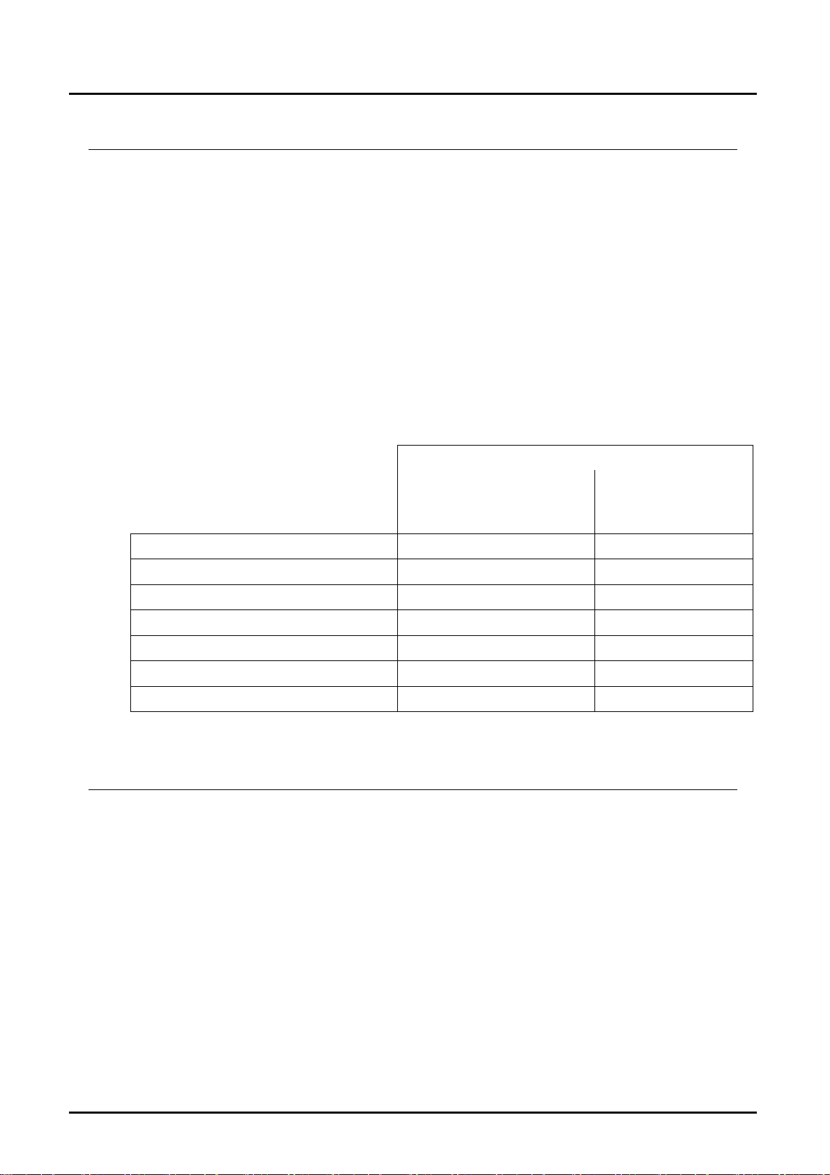
2. Note
Please read these operating instructions before unpacking and putting the unit
into operation. Follow the instructions precisely as described herein.
The devices are only to be used, maintained and serviced by persons familiar
with these operating instructions and in accordance with local regulations
applying to Health & Safety and prevention of accidents.
When used in machines, the measuring unit should be used only when the
machines fulfil the EC-machine guidelines.
as per PED 2014/68/EU
In acc. with Article 4 Paragraph (3), "Sound Engineering Practice", of the
PED 2014/68/EU no CE mark.
Pipe
Diagram 7
group 1
no dangerous fluids
RCD-..05 - RCD..30 Art. 4, § 3 Art. 4, § 3
RCD-1135, RCD-1140 Art. 4, § 3 Cat. I
RCD-1235, RCD-1240 Cat. I Cat. II
RCD-1145, RCD-1150 Art. 4, § 3 Cat. I
RCD-1245, RCD-1250 Cat. I Cat. II
RCD-1155, RCD-1160, RCD-1165 Cat. I not deliverable
RCD-1260, RCD-1265 Cat. I Cat. II
dangerous fluids
3. Instrument Inspection
Instruments are inspected before shipping and sent out in perfect condition.
Should damage to a device be visible, we recommend a thorough inspection of
the delivery packaging. In case of damage, please inform your parcel service /
forwarding agent immediately, since they are responsible for damages during
transit.
Scope of delivery:
The standard delivery includes:
Differential Pressure Flow Meter / Monitor model: RCD
Operating Instructions
Diagram 6
group 2
RCD K07/0818 page 3
Page 4

RCD
4. Regulation Use
Any use of the Differential Pressure Flow Meter / Monitor, model: RCD, which
exceeds the manufacturer’s specification may invalidate its warranty. Therefore
any resulting damage is not the responsibility of the manufacturer. The user
assumes all risk for such usage.
5. Operating Principle
The Kobold Flow Meter is used for measuring and monitoring the flow velocity of
liquids and gases. The device works in accordance with the well-known principle
of the Venturi nozzle. A small pressure difference proportional to the flow is
produced by the flowing medium at a cross-sectional constriction (nozzle) in the
device housing. The shape of the nozzle is based on the particular flow value
whereby flow characteristic remains constant over the entire measuring range.
Pressure sensing ports are located in the flow body to measure the resulting
differential pressure and send it to a differential-pressure measuring cell fitted in
the display case. If the flow is exceeded, the differential-pressure measuring cell
is protected by mechanical stops. In the case of mechanical displays the flow rate
measured by the differential pressure measuring cell is indicated on a pointer
element which is calibrated in l/min water or Nm3/h air. On electronic displays the
mechanical motion is converted to an electrical signal by a Hall sensor. The
electronics serves to display and monitor the volumetric flow.
6. Mechanical Connection
6.1. Check Service Conditions
Flow
Max. operating pressures
Max. operating temperature
Medium
Mounting position
When the medium is not in our substance database:
operating density
operating viscosity
page 4 RCD K07/0818
Page 5

RCD
6.2. Installation
Flow in direction of arrow (universal)
Avoid pressure and tensile loads
mount inlet and outlet piping at distances of 50 mm from the connections
Check connections for leaks
Pay attention to the inlet and outlet path (see drawings below)
2 x 90°- elbow
Control valve
P
3 - dimensional
P
2 x 90°- elbow
50 x D 5 x D
P
25 x D 5 x D
90°- elbow or
T - piece
40 x D
P
20 x D 5 x D
5 x D
P
Extention
P
18 x D 5 x D
Reduction
15 x D 5 x D
RCD K07/0818 page 5
Page 6

RCD
7. Electrical Connection
7.1. Mechanical Pointer Indication (..Z...)
without electrical connection
7.2. Compact Electronics:
(..C30R, ..C30M, ..C34P, ..C34N)
see
Operating instructions supplement
for compact electronics with frequency output
7.3. ADI Electronic
see
Operating instructions supplement
for ADI electronic display
8. Commissioning
8.1. Mechanical Pointer Indication (..Z...)
Attention! Remove transportation safety screw and screw in the
sealing screw from the bag into the thread M3.
8.2. Setting Compact Electronics
see
Operating instructions supplement
for compact electronics with frequency output
8.3. Setting ADI Electronic
see
Operating instructions supplement
for ADI electronic display
page 6 RCD K07/0818
Page 7

RCD
9. Maintenance
The measuring instrument requires no maintenance when the measured medium
leaves no deposits. To prevent fouling the flow meter pressure sensing ports, we
recommend that a filter is installed, for example the magnetic filter, model MFR.
Work on the sensor and electronics should only be carried out by the supplier,
otherwise the warranty is void.
10. Technical Information
10.1. Sensor Data
Measuring range: see name plate
Measuring accuracy: 3 % of F.S.
Reproducibility: 1 % of F.S.
Process temperature: RCD... mechanical: -20 °C…+100 °C
RCD... electronic: -20 °C…+80 °C
Ambient temperature: max. 80 °C
Max. operating pressure: 25 bar (RCD-1155, RCD-1160, RCD-1165)
40 bar (all others)
Protection: IP 65
Materials:
Flow housing: RCD-x1..: brass casting
RCD-x2..: stainless steel 1.4581
Differential pressure housing: RCD-x1..: brass casting
RCD-x2..: stainless steel 1.4571
Pressure measuring cell: stainless steel 1.4571
Venturi nozzle: stainless steel 1.4571
Gaskets: RCD-x1..: NBR
RCD-x2..: FPM
10.2. Displays/Electronics
Mechanical pointer indication:
Display: 270 °
Display case: aluminium / polyamide
Front cover: polycarbonate
Option: special scales for other gases and liquids.
Please specify medium, density, viscosity,
operating pressure and temperature
RCD K07/0818 page 7
Page 8

RCD
Compact electronics:
Display: 3-digit LED
Analogue output: (0) 4 - 20 mA adjustable, max. 500 Ω
Switching outputs: 1 (2) semiconductor PNP or
NPN, factory set
Contact operation: N/C / N/O frequency programmable
Setting: via 2 buttons
Supply: 24 V
± 20 %, 3-wire, approx. 100 mA
DC
Electrical connection: plug connector M12 x 1
ADI electronics
Display: bar graph and 5-digit digital display
Analogue output: (0)4-20 mA, 0-10 V
DC
Two switching outputs: relay/changeover contacts
max. 250 VAC/5 A resistive load,
max. 30 V
DC
/ 5 A
Setting: via 4 buttons
Power supply: 100...240 V
18...30 VAC/10...40 V
±10% or
AC
DC
Electrical connection: pluggable terminal block via cable gland
page 8 RCD K07/0818
Page 9

RCD
11. Order Details
Order details (example: RCD 1195H G4 K 0 0 0)
Meas.
range
water
[L/min]
0.5…3.3 2.80
0.5…4.2 3.15
0.5…5.2 3.50
1.0...6.8 4.00
1.0...8.6 4.50
1.0...10.6 5.00
2.0...13.2 5.60
2.0...16.8 6.30
2.0...21.4 7.10
3.0…27.0 8.00
5.0…34.5 9.00
5.0…42.4 10.00
10.0...58.0 11.20
10.0...66.0 12.50
10.0...85.0 14.00
20.0...118 16.00
20.0...132 17.50
20.0...148 18.00
20.0...168 19.20
30.0...275 26.00
50.0...350 28.00
50.0…435 31.00
100...700 40.00
100...910 43.50
100...1060 51.00
200...1540 60.00
300...2350 67.00
Orifice
[mm]
Model
Material
brass casting
RCD 1195H RCD 1295H
RCD 1100H RCD 1200H
RCD 1190H RCD 1290H
RCD 1191H RCD 1291H
RCD 1101H RCD 1201H
RCD 1192H RCD 1292H
RCD 1102H RCD 1202H
RCD 1103H RCD 1203H
RCD 1104H RCD 1204H
RCD 1106H RCD 1206H
RCD 1109H RCD 1209H
RCD 1110H RCD 1210H
RCD 1114H RCD 1214H
RCD 1115H RCD 1215H
RCD 1116H RCD 1216H
RCD 1117H RCD 1217H
RCD 1125H RCD 1225H
RCD 1126H RCD 1226H
RCD 1130H RCD 1230H
RCD 1135H RCD 1235H
RCD 1137H RCD 1237H
RCD 1139H RCD 1239H
RCD 1145H RCD 1245H G9 = G 2
RCD 1150H RCD 1250H GB = G 3
RCD 1155H RCD 1255H
RCD 1160H RCD 1260H
RCD 1165H RCD 1265H
Material
st. steel
G4 = G 1/2 N4 = 1/2 NPT
G4 = G 1/2
G5 = G 3/4
G4 = G 1/2
G5 = G 3/4
G6 = G 1
G5 = G 3/4
G6 = G 1
G6 = G 1
G8 = G 1 1/2
G8 = G 1 1/2
G9 = G 2
GB = G 3 NB = 3 NPT
Evaluating electronics
Mechanical pointer indication
Indication Flow direction Location of ind.
Z = pointer indicat., 270 °
ADI-electronics**
Indication Supply Output Contacts
0 = 100-240 V
K = bargraph /digital
Indication Supply Output/contacts
C = digital 3 = 24 V
** Please specify flow direction in the order (expect from top to bottom)
Please specify the operating conditions in the order
3 = 18-30 V
10-40 VAC
AC/DC
AC
Compact electronics**
DC
Connection
G-thread NPT
N4 = 1/2 NPT
N5 = 3/4 NPT
N4 = 1/2 NPT
N5 = 3/4 NPT
N6 = 1 NPT
N5 = 3/4 NPT
N6 = 1 NPT
N6 = 1 NPT
N8 = 1 1/2 NPT
N8 = 1 1/2 NPT
N9 = 2 NPT
N9 = 2 NPT
NB = 3 NPT
L = from left
R = from right
B = from bottom
0 = without
4 = (0)4-20 mA,
0-10 V
0R = 2 x Open Collector, PNP
0M = 2 x Open Collector, NPN
4P = 4-20 mA, 1 x Open Coll. PNP
4N = 4-20 mA; 1 x Open Coll. NPN
2 = 2 changeover contacts
L = left
R = right
T = top
B = bottom
RCD K07/0818 page 9
Page 10

RCD
Order details (example: RCD 1195L G4 K 0 0 0)
Range air Orifice
1 bar abs. / 20 °C
/h]*
[m³
N
[mm]
Material
Alu bronze
Model Connection
Material
st. steel
G-thread NPT
0.50...5.35 2.80
1.00...6.70 3.15
1.00...8.30 3.50
1.00...10.9 4.00
2.00...13.8 4.50
2.00...17.0 5.00
2.00...21.4 5.60
3.00...27.0 6.30
5.00...34.5 7.10
5.00...43.5 8.00
10.0...55.0 9.00
10.0...68.0 10.00
10.0...78.0 11.20
10.0...97.0 12.50
20.0...116 14.00
20.0...158 16.00
20,0...188 17.50
20.0...198 18.00
30.0...225 19.20
50.0...375 26.00
50.0...515 28.00
100...630 31.00
100...910 40.00
200...1160 43.50
200...1360 51.00
400...2000 60.00
300...2750 67.00
* m³N/h correspond to a flow rate at 0 °C; 1013 mbar
RCD 1195L RCD 1295L
RCD 1100L RCD 1200L
RCD 1190L RCD 1290L
RCD 1191L RCD 1291L
RCD 1101L RCD 1201L
RCD 1192L RCD 1292L
RCD 1102L RCD 1202L
RCD 1103L RCD 1203L
RCD 1104L RCD 1204L
RCD 1106L RCD 1206L
RCD 1109L RCD 1209L
RCD 1110L RCD 1210L
RCD 1114L RCD 1214L
RCD 1115L RCD 1215L
RCD 1116L RCD 1216L
RCD 1117L RCD 1217L
RCD 1125L RCD 1225L
RCD 1126L RCD 1226L
RCD 1130L RCD 1230L
RCD 1135L RCD 1235L
RCD 1137L RCD 1237L
RCD 1139L RCD 1239L
RCD 1145L RCD 1245L
RCD 1150L RCD 1250L
RCD 1155L RCD 1255L
RCD 1160L RCD 1260L
RCD 1165L RCD 1265L
G4 = G 1/2 N4 = 1/2 NPT
G4 = G 1/2
G5 = G 3/4
G4 = G 1/2
G5 = G 3/4
G6 = G 1
G5 = G 3/4
G6 = G 1
G6 = G 1
G8 = G 1 1/2
G8 = G 1 1/2
G9 = G 2
G9 = G 2
GB = G 3
GB = G 3 NB = 3 NPT
N4 = 1/2 NPT
N5 = 3/4 NPT
N4 = 1/2 NPT
N5 = 3/4 NPT
N6 = 1 NPT
N5 = 3/4 NPT
N6 = 1 NPT
N6 = 1 NPT
N8 = 1 1/2 NPT
N8 = 1 1/2 NPT
N9 = 2 NPT
N9 = 2 NPT
NB = 3 NPT
Evaluating electronics
Mechanical pointer indication
Indication Flow direction Location of ind.
L = from left
Z = pointer indicat., 270 °
ADI-electronics**
Indication Supply Output Contacts
0 = 100-240 V
K = bargraph /digital
Indication Supply Output/contacts
C = digital 3 = 24 V
** Please specify flow direction in the order (expect from top to bottom)
Please specify the operating conditions in the order
3 = 18-30 V
10-40 VAC
AC/DC
AC
Compact electronics**
DC
R = from right
B = from bottom
0 = without
4 = (0)4-20 mA,
0-10 V
0M = 2 x Open Collector, NPN
4P = 4-20 mA, 1 x Open Coll. PNP
4N = 4-20 mA; 1 x Open Coll. NPN
L = left
R = right
T = top
B = bottom
2 = 2 changeover contacts
0R = 2 x Open Collector, PNP
page 10 RCD K07/0818
Page 11

RCD
12. Dimensions
RCD...Z with mechanical display
RCD...C with compact electronics
Screw
thread
G 1/2 191 78 hex 27 143 ca. 2,0 kg
G 3/4 191 78 hex 41 143 ca. 2,3 kg
G1 191 78 hex 41 143 ca. 2,2 kg
G 1 1/2 206 78 hex 55 158 ca. 2,6 kg
G 2 204 81 hex 70 156 ca. 2,8 kg
G3 221 106 hex 100 173 ca. 5,1 kg
Screw
thread
G 1/2 191 78 hex 27 143 ca. 2,1 kg
G 3/4 191 78 hex 41 143 ca. 2,4 kg
G1 191 78 hex 41 143 ca. 2,2 kg
G 1 1/2 206 78 hex 55 158 ca. 2,6 kg
G 2 204 81 hex 70 156 ca. 2,9 kg
G3 221 106 hex 100 173 ca. 5,2 kg
A B C D Weight
(approx.)
A B C D Weight
(approx.)
RCD...K with ADI electronic
(same dimensions for RCD...D and RCD...K)
Screw
thread
G 1/2 191 78 hex 27 143 ca. 3,4 kg
G 3/4 191 78 hex 41 143 ca. 3,7 kg
G1 191 78 hex 41 143 ca. 3,6 kg
G 1 1/2 206 78 hex 55 158 ca. 3,9 kg
G 2 204 81 hex 70 156 ca. 4,2 kg
G3 221 106 hex 100 173 ca. 6,5 kg
A B C D Weight
(approx.)
RCD K07/0818 page 11
Page 12

RCD
13. EU Declaration of Conformance
We, KOBOLD-Messring GmbH, Hofheim-Ts, Germany, declare under our sole
responsibility that the product:
Differential Pressure Flow Meter / Monitor model: RCD -...
to which this declaration relates is in conformity with the standards noted below:
EN 61000-6-4:2011
Electromagnetic compatibility (EMC) - Part 6-4: Generic standards - Emission
standard for industrial environments
EN 61000-6-2:2005
Electromagnetic compatibility (EMC) - Part 6-2: Generic standards - Immunity for
industrial environments
EN 61010-1:2010
Safety requirements for electrical equipment for measurement, control and
laboratory use - Part 1: General requirements
EN 60529:2014
Degrees of protection provided by enclosures (IP Code)
EN 50581:2012
Technical documentation for the assessment of electrical and electronic products
with respect to the restriction of hazardous substances
in accordance with the general requirements of the guideline
2014/35/EU Low Voltage Directive
2014/30/EU EMC Directive
2011/65/EU RoHS (category 9)
2014/68/EU PED
Category III (IV) Diagram 1, vessel, group 1 dangerous fluids
Module D, marking CE0575
Notified body: DNV GL
Certificate No. PEDD000000R
Hofheim, 02. Aug. 2018
H. Peters M. Wenzel
General Manager Proxy Holder
page 12 RCD K07/0818
 Loading...