

Page 1
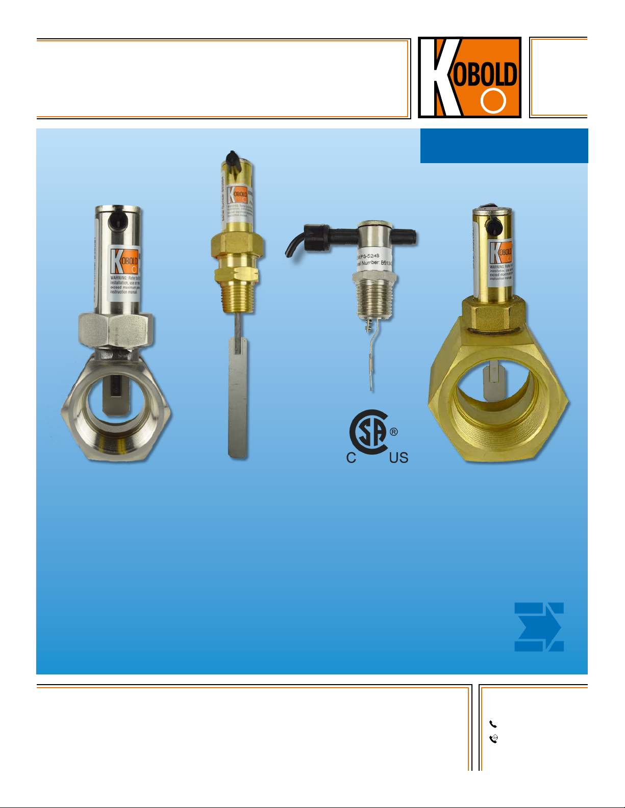
Paddle Type Flow Switch
for Liquids
measuring
•
monitoring
•
analyzing
PSR / PS
• Switch Point Adjustable
• Easy to Install
• Brass or SS Construction
• Low Cost
• Maximum Pressure, Brass: 1450 PSIG
• Maximum Pressure, SS: 3625 PSIG
KOBOLD companies worldwide:
ARGENTINA, AUSTRALIA, AUSTRIA, BELGIUM, BULGARIA, CANADA, CHILE, CHINA, COLOMBIA,
CZECH REPUBLIC, EGYPT, FRANCE, GERMANY, HUNGARY, INDIA, INDONESIA, ITALY, MALAYSIA,
MEXICO, NETHERLANDS, PERU, POLAND, REPUBLIC OF KOREA, ROMANIA, SINGAPORE, SPAIN,
SWITZERLAND, TAIWAN, THAILAND, TUNISIA, TURKEY, UNITED KINGDOM, USA, VIETNAM
01/06-20-2018
KOBOLD Instruments, Inc.
1801 Parkway View Drive
Pittsburgh, PA 15205
Main Ofce:
1.800.998.1020
1.412.788.4890
info@koboldusa.com
www.koboldusa.com
Page 2
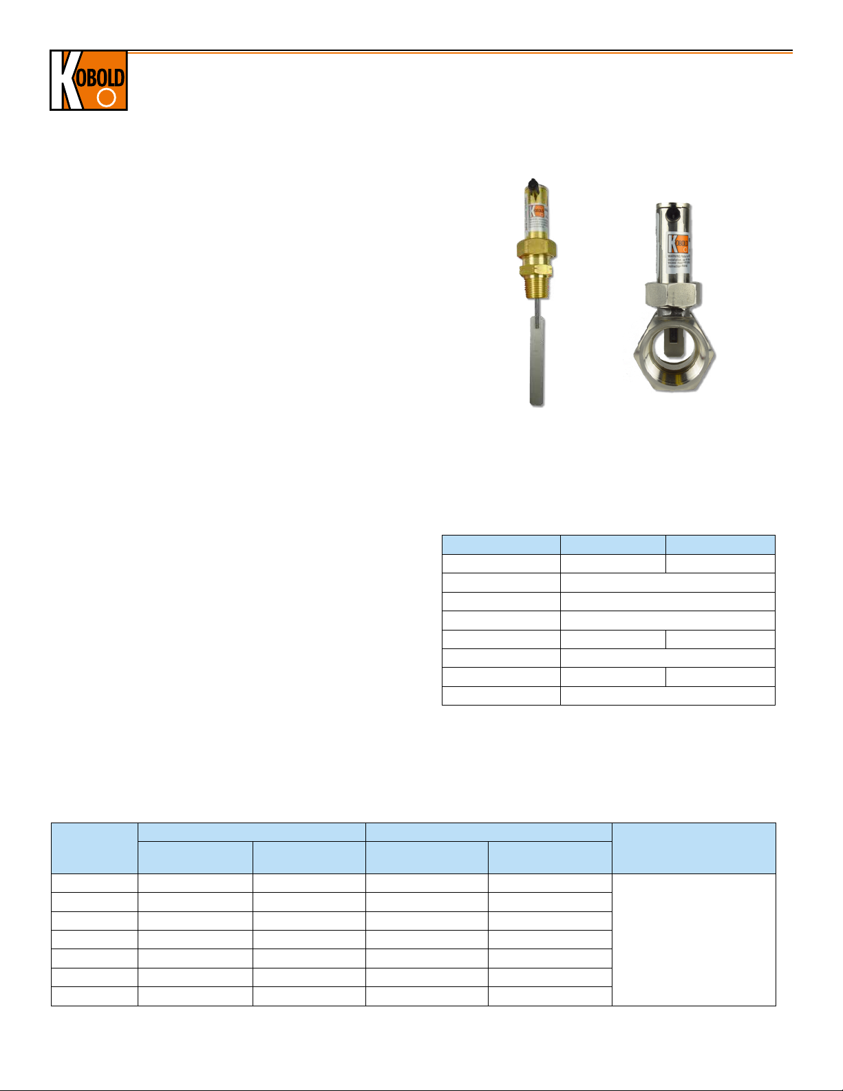
Paddle Type Flow Switch Models PSR/PS
Description
The KOBOLD PSR and PS are simple, economical and reliable
monitors for flow switching applications. They operate as follows:
The flowing media presses against the paddle fitted to one end of
a balance arm which is in direct contact with a pre-stressed leaf
spring. At the other end of the arm is a permanent magnet. This
magnet actuates a reed contact in a bistable fashion located within
a movable housing located outside of the media. The reed contact
switches on or off depending on the position of the magnet and
the switch housing. The switch status may then be used to control
flow as the contacts can be set to normally open or normally
closed. The PSR is made of brass or stainless steel with 1/4"
NPT to 1-1/2" NPT fittings. The PS is made of brass or stainless
steel with a 1/2" NPT fitting and is designed for installation in 2"
to 8" pipes. Common applications include: cooling and lubricant
circuits, dry running protection for pumps, prevention of low water
levels, and monitoring for pipe breakage.
Specifications
Switching Tolerance: ± 15%
Media Temperature
Brass/NBR Seal: -4...158 °F
SS/FPM Seal: 14...230 °F
Ambient Temperature: Max. 176 °F
Max. Pressure
Brass: 1/4"...1" = 1450 PSIG
1-1/4"...1-1/2" = 360 PSIG
SS: 1/4"...1" = 3600 PSIG
1-1/4"...1-1/2" = 580 PSIG
Ingress Protection: IP 65
Mounting Orientation: Horizontal Flow Preferred
Max Flow Rate: 5x Switching Range, Increasing
Maximum Contact Ratings (cCSAus):
SPST Contact: 2A, 20 VAC, 0.18 A, 230 VAC,
max. 40 W
SPDT Contact: 0.13 A, 150 VAC, 0.5 A, 40 VAC,
max. 20 W
Cable: PVC Jacketed
Cable Length: Standard: 5 Ft. (1.5m),
Optional (SPST only): 10, 15 or 21 Ft.
Model PS Model PSR
Materials
PSR/PS-51.. PSR/PS-52..
Case MS58 Brass 304 SS
Paddle 304 Stainless Steel
Leaf Spring 301 Stainless Steel
Balance Arm 301 Stainless Steel
Sleeve MS58 Brass 304 SS
Magnet Oxide Ceramics
Seal NBR FKM
Contact Tube Polyamide, Glass Reinforced
*U.S. Patent Number: 4,827,092
Order Details: PSR w/Standard Switching Ranges (Example: PSR-5105)
Connection
(NPT)
1/4" 0.6...1.2 0.4...1.2 PSR-5105 PSR-5205
3/8" 0.7...1.5 0.6...1.4 PSR-5110 PSR-5210
1/2" 0.7...1.6 0.5...1.6 PSR-5115 PSR-5215
3/4" 2.0...3.5 1.6...3.4 PSR-5120 PSR-5220
1" 2.0...4.8 1.9...4.5 PSR-5125 PSR-5225
1-1/4" 5.2...9.7 5.3...8.5 PSR-5132 PSR-5232
1-1/2" 6.1...15.2 6.2...14.0 PSR-5140 PSR-5240
*Listed values are valid only for horizontal installations
2
Approximate Switching Range* Model / Material
Increasing GPM
(Water)
Decreasing GPM
(Water)
Brass Stainless Steel
www.koboldusa.com
Options
..U = SPDT Switch, 5 Ft. Cable
..EC10 = SPST w/10 Ft. Cable
..EC15 = SPST w/15 Ft. Cable
..EC21 = SPST w/21 Ft. Cable
No responsibility taken for errors;
subject to change without prior notice.
Page 3

Paddle Type Flow Switch Models PSR/PS
Order Details: PSR with Special Switching Ranges (Example: PSR-5105 2)
Connection
(NPT)
1/4"
3/8"
1/2"
3/4"
1"
*Listed values are valid only for horizontal installations
Approximate Switching Range* Model / Material
Increasing GPM
(Water)
Decreasing GPM
(Water)
Brass Stainless Steel
1.3...1.7 0.9...1.6 PSR-5105 2 PSR-5205 2
1.5...2.0 1.2...2.0 PSR-5105 1 PSR-5205 1
1.5...1.8 1.2...1.8 PSR-5110 2 PSR-5210 2
1.8...2.2 1.5...2.2 PSR-5110 1 PSR-5210 1
2.2...2.8 1.9...2.7 PSR-5115 2 PSR-5215 2
2.5...3.2 2.2...3.1 PSR-5115 1 PSR-5215 1
4.7...6.5 4.0...6.1 PSR-5120 5 PSR-5220 5
5.4...7.9 4.3...7.4 PSR-5120 4 PSR-5220 4
9.2...12.7 8.1...12.3 PSR-5120 1 PSR-5220 1
4.7...7.0 3.4...6.5 PSR-5125 7 PSR-5225 7
6.9...9.5 5.7...9.0 PSR-5125 5 PSR-5225 5
7.9...11.3 6.6...10.8 PSR-5125 4 PSR-5225 4
12.6...17.7 11.6...17.1 PSR-5125 1 PSR-5225 1
Option
..U = SPDT Switch, 5 Ft. Cable
..EC10 = SPST w/10 Ft. Cable
..EC15 = SPST w/15 Ft. Cable
..EC21 = SPST w/21 Ft. Cable
Order Details: PS (Example: PS-5149)
Approximate Switching Range*
Pipe Size
2" 18...24 16...22
3" 48...66 45...62
4" 84...106 79...101
6" 185...242 176...237
2" 13...16 11...15
3" 41...48 38...44
4" 57...70 53...66
6" 147...159 137...156
4" 24...30 19...27
8" 101...141 88...123
*Listed values are valid only for horizontal installations
Increasing GPM
(Water)
Decreasing GPM
(Water)
Connection
1/2" NPT
Model / Material
Brass Stainless Steel
PS-5149 PS-5249
PS-5152 PS-5252
PS-5114 PS-52146" 53...75 44...62
Option
..U = SPDT Switch, 5 Ft. Cable
..EC10 = SPST w/10 Ft. Cable
..EC15 = SPST w/15 Ft. Cable
..EC21 = SPST w/21 Ft. Cable
No responsibility taken for errors;
subject to change without prior notice.
www.koboldusa.com
3
Page 4

Dimensions
Paddle Type Flow Switch Models PSR/PS
Model PS-..49 Model PSR
22 AF
0.78"
0.48"
Model D1 L
PS-..49 1/2" NPT 2.32"
PS-..52 1/2" NPT 2.22"
PS-..14 1/2" NPT 4.52"
Models PS-..52 and PS-..14
1.34"
27 AF
2
3.03"
0.75"
0.48"
Model D1 L L
PSR-..05 1/4" NPT 1.97" 0.39" 3.70" 1.06"
PSR-..10 3/8" NPT 1.97" 0.39" 3.70" 1.06"
PSR-..15 1/2" NPT 1.97" 0.39" 3.70" 1.06"
PSR-..20 3/4" NPT 2.05" 0.59" 3.85" 1.25"
PSR-..25 1" NPT 2.20" 0.59" 4.08" 1.54"
PSR-..32 1-1/4" NPT 2.60" - 4.49" 1.97"
PSR-..40 1-1/2" NPT 2.60" - 4.79" 2.36"
30 AF
1 AF
1 AF
L
1
2
Switch Point Setting
To adjust the switch set-point, slightly loosen the two screws that
secure the locking washer at the top of the casing and move the
contact unit. Blue/white & red arrows located on the contact unit
serve as an adjustment aid. The front edge of the locking washer
serves as an adjustment mark.
N/O Contact
The switching volume may then be adjusted at the red arrow. The
minimum switching values specified in the table are set by moving
the contact unit in the flow direction. The maximum switching values
noted in the table are set by moving the contact unit against the
direction of flow. Evenly tighten the two screws that secure the
locking washer after the desired settings have been made.
N/C Contact
The switching volume may then be adjusted at the blue/white arrow.
The minimum switching values specified in the table are set by
moving the contact unit in the flow direction. The maximum switching
values noted in the table are set by moving the contact unit against
the direction of flow. Evenly tighten the two screws that secure the
locking washer after the desired settings have been made.
4
www.koboldusa.com
No responsibility taken for errors;
subject to change without prior notice.
 Loading...