

Page 1
Operating Instructions
for
Display Pressure Switch
Model: PSD
Page 2

PSD
We don’t accept warranty and liability claims neither upon this publication nor in
case of improper treatment of the described products.
The document may contain technical inaccuracies and typographical errors. The
content will be revised on a regular basis. These changes will be implemented in
later versions. The described products can be improved and changed at any time
without prior notice.
© Copyright
All rights reserved.
1. Contents
1. Contents ........................................................................................................ 2
2. Note .............................................................................................................. 3
3. Instrument Inspection .................................................................................... 3
4. Regulation Use .............................................................................................. 3
5. Operating Principle ........................................................................................ 4
6. Mechanical Connection ................................................................................. 4
7. Electrical Connection .................................................................................... 5
7.1 Output signal / supply voltage ................................................................ 5
8. Operating menu ............................................................................................ 6
9. Type label description ................................................................................... 8
10.Technical Information .................................................................................... 8
11.Terminology ................................................................................................ 11
12.Order Codes ............................................................................................... 13
13.Dimensions ................................................................................................. 13
14.EU Declaration of Conformance .................................................................. 14
Manufactured and sold by:
Kobold Messring GmbH
Nordring 22-24
D-65719 Hofheim
Tel.: +49(0)6192-2990
Fax: +49(0)6192-23398
E-Mail: info.de@kobold.com
Internet: www.kobold.com
page 2 PSD K02/0118
Page 3

PSD
2. Note
Please read these operating instructions before unpacking and putting the unit
into operation. Follow the instructions precisely as described herein.
The devices are only to be used, maintained and serviced by persons familiar
with these operating instructions and in accordance with local regulations
applying to Health & Safety and prevention of accidents.
When used in machines, the measuring unit should be used only when the
machines fulfil the EC-machine guidelines.
3. Instrument Inspection
Instruments are inspected before shipping and sent out in perfect condition.
Should damage to a device be visible, we recommend a thorough inspection of
the delivery packaging. In case of damage, please inform your parcel service /
forwarding agent immediately, since they are responsible for damages during
transit.
Scope of delivery:
The standard delivery includes:
Display Pressure Switch model: PSD
Operating Instructions
4. Regulation Use
Any use of the Display Pressure Switch, model: PSD, which exceeds the
manufacturer’s specification, may invalidate its warranty. Therefore, any resulting
damage is not the responsibility of the manufacturer. The user assumes all risk
for such usage.
PSD K02/0118 page 3
Page 4
PSD
5. Operating Principle
KOBOLD is a leading international supplier of high quality sensors and monitoring
instruments among other things for measurement of pressure and temperature.
The PSD is the ideal combination of pressure switch and transmitter with a
pressure display. The parameters can be set on the device. The settings in
combination with a comprehensive set of options make the PSD suitable for a
wide range of demanding applications.
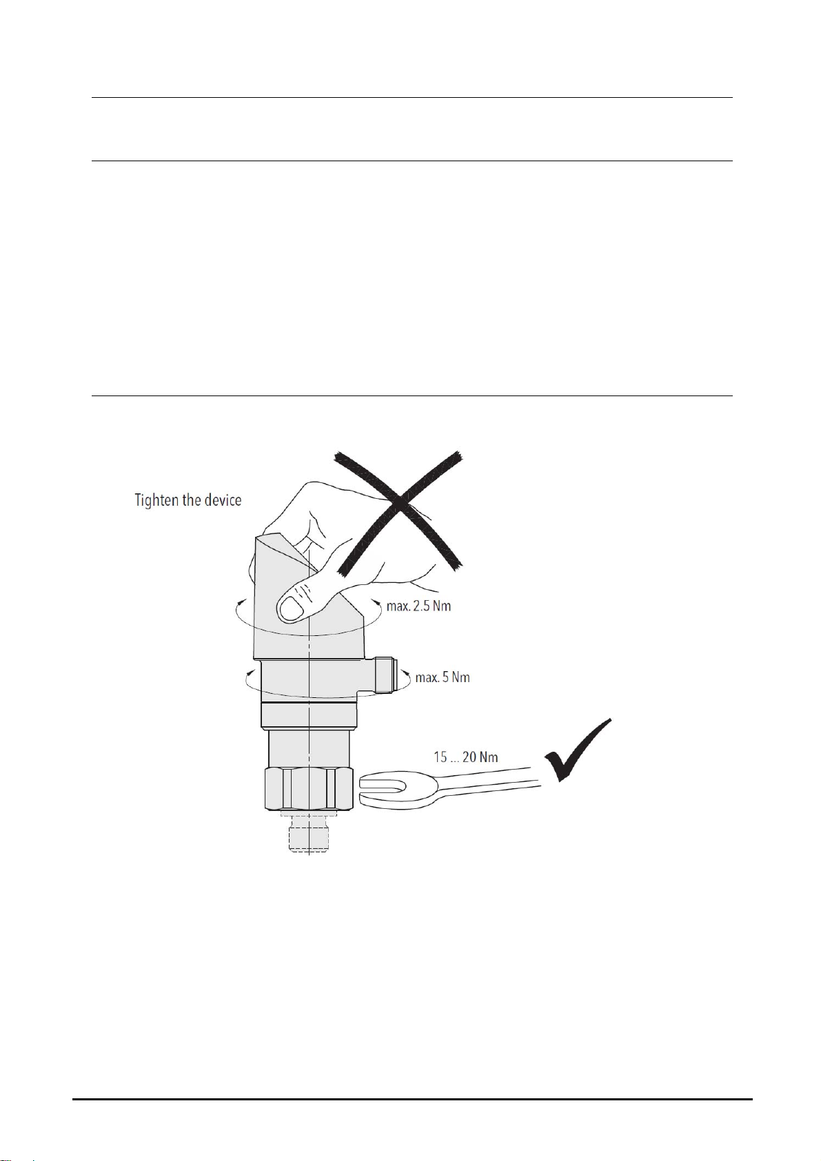
6. Mechanical Connection
page 4 PSD K02/0118
Page 5
PSD
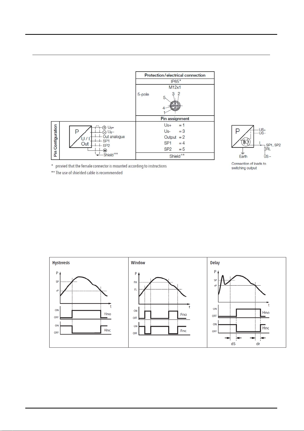
7. Electrical Connection
7.1 Output signal / supply voltage
Output I
4...20 mA ≤ 30 mA 15...30 VDC
0...10 VDC ≤ 30 mA 15...30 VDC
Switching output functions
SUPPLY
U
SUPPLY
PSD K02/0118 page 5
Page 6

PSD
8. Operating menu
page 6 PSD K02/0118
Page 7

PSD
Parameter
Name Standard setting
Switch point SP1 (hysteresis mode)
Upper switch point FH1 (window mode)
Reset point RP1 (hysteresis mode)
Lower switch point FL1 (window mode)
Switch point SP2 (hysteresis mode)
Upper switch point FH2 (window mode)
Reset point RP2 (hysteresis mode)
Lower switch point FL2 (window mode)
Switch point delay time SP1 (hysteresis
mode)
Switch point delay time FH1 (window
mode)
Switch point delay time RP1 (hysteresis
mode)
Switch point delay time FL1 (window
mode)
Switch point delay time SP2 (hysteresis
mode)
Switch point delay time FH2 (window
mode)
Switch point delay time RP2 (hysteresis
mode)
Switch point delay time FL2 (window
mode)
Functions switching output 1 Hysteresis, closer (Hno)
Functions switching output 2 Hysteresis, closer (Hno)
Pressure units bar bar, psi, MPa, kPa, mWC uni
Measuring range adjustment 100 % nominal pressure 50…100% nominal pressure P-EP
Damping (analogue output) 0.01 s 0.01…3.00 s (time constant) dAA
Display rotation no no, yes (180°) disr
Display mode Current pressure value
Display update 2 1, 2, 5, 20 Hz duPd
(accessory ZS)
75% measuring range
25% measuring range
75% measuring range
25% measuring range
0 0...99.99 s dS1
0 0...99.99 s dR1
0 0...99.99 s dS2
0 0...99.99 s dR2
Hysteresis NO (Hno), hysteresis NC (Hnc),
window NO (Fno), window NC (Fnc)
Hysteresis NO (Hno), hysteresis NC (Hnc),
window NO (Fno), window NC (Fnc)
current, highest, lowest, display off
decimal places selectable (max. 3)
Value range Short name
SP1RP1
FH1FL1
hysteresis≥1% FS
RP1<SP1
FL1<FH1
hysteresis ≥ 1% FS
SP2RP2
FH2FL2
hysteresis≥ 1% FS
RP2<SP2
FL2<FH2
hysteresis ≥ 1% FS
Pressure value:
Current value:
SP1
RP1
SP2
RP2
ou1
ou2
dis
PSD K02/0118 page 7
Page 8

PSD
9. Type label description
10. T echnical Information
Measuring principle: thin film on steel
Measuring range: -1...+1.5 to 0...600 bar
-14.5...+22 to 0...7500 psi
adjustable 50...100 % FS
Output signal: 4...20 mA
0...10 V
Switching output: 2 transistors PNP
Accuracy@ 25° C typ.: ±0.5 % FS typ.
Media temperature: -25° C...+85° C
Ambient temperature: -25° C...+85° C
Pressure unit for display: bar, psi, MPa, kPa, m WC, mm WC
Electrical data
Output/supply voltage: 4...20 mA: 24 or 0-10 V
Switch-on-delay: typ. 200 ms
Inverse-polarity protection,
Short-circuit strength
@ 25° C during 5 min.; integrated
Current consumption: ≤30 mA
24 (15...30) VDC
switchable mA or V
DC,
DC/
page 8 PSD K02/0118
Page 9

PSD
Environmental conditions
Media temperature: -25° C...+85° C
Ambient temperature: -25° C...+85° C
Protection1): IP65
Humidity: max. 95% relative
Vibration: 10 g (10...2000 Hz)
Shock: 50 g/ 3 ms
1)
see electrical connection
Analogue output
Output signal: switchable 4-20 mA or 0-10 V
Accuracy: TEB
2)
@ -25 °C...+85° C
[% FS typ.] ± 1.75
accuracy @ +25° C
[% FS typ.] ±0.5
2)
NLH
@ +25° C (BSL)
[% FS typ.] ±0.2
TC
2)
zero point and span
[% FS typ.] ±0.03
long term stability 1 year
[% FS typ.] ±0.1
Current limiting output signal: 4-20 mA (overload)
0...10 VDC: <40 mA (short-circuit)
Damping (rise-time): 0.01...3.00 s/10...90% nominal pressure
Switching output
Accuracy: accuracy@ +25° C
[% FS typ.] ± 0.5
TEB2) @ -25 °C...+85° C
[% FS typ.] ± 1.0
accuracy @ +25° C
long term stability 1 year
[% FS typ.] ±0.3
Adjustment range of
switchpoints: 0...100% FS
Switching hysteresis: ≥ 1% FS switchpoint reset point
Switching resistance: ≤ 3 Ω
Output function: hysteresis, window; normally open (NO),
normally closed (NC)
Switching current: ≤ 0.5 A each switching output
Current limiting: ≤ 2 A each switching output
Switching frequency: max. 200 Hz
Delay time: 0...99.99 s
2)
see »Terminology«
DC
PSD K02/0118 page 9
Page 10

PSD
Display
Display: 4-digit 7-segment display 180 °
flippable with disable function
standard decimal places:
≤9: 3 decimal places
10...99: 2 decimal places
100...999: 1 decimal place
Switching status indication: 2 LED, red
Operation: with 3 buttons and menu navigation
according to VDMA 24574-1
Display reduction: 0.1 % FS
Display range: -3...103% FS
Setting parameters: see table “Parameter”
Mechanical data
Sensor (wetted parts) 1.452 (AISI630)
Pressure connection
(wetted parts): 1.452 (AISI630)
Housing: steel, die cast metal galvanised,
display housing plastic
Connection: G¼ male,
adapter can be ordered as separate item
Sealing: FPM
Male electrical plug: PA-plug M12x1.5 pin
Mounting torque: 15...20 Nm
Housing alignment: display 335 ° rotatable, max. 2.5 Nm
electrical connection 343° rotatable, max. 5 Nm
Pressure peak
damping element: ø 0.4 mm
Weight: ~189 g
page 10 PSD K02/0118
Page 11

PSD
11. T erminology
Non-linearity
The largest deviation from the effective characteristic line of an ideal reference
line. The reference line can be defined as a limit point adjustment, a BSL or a
BSL through 0.
Specifications: Non-linearity, Hysteresis
BSL through Zero
As an additional requirement for the minimum value adjustment, the BSL
through zero (also BSL/0) must go straight through zero or the origin.
Specifications: Accuracy NLH (BSL through zero)
PSD K02/0118 page 11
Page 12

PSD
BSL Best Straight Line
The reference line according to the BSL or the minimum value adjustment is
placed in such a way that the maximum positive and negative deviations are as
small as possible.
Specifications: Non-linearity, Hysteresis
Specifications: Accuracy NLH (BSL)
NLH Non-linearity an d Hysteresis
Largest deviation from the ideal characteristic line (BSL, BSL/0 or limit point). In
pressure measuring instruments, the non-linearity and pressure hysteresis are
given together at a constant temperature.
Temperature Coefficient TC
Change of measured value for zero point and span as a result of changes in
temperature
Long-term Stability Long-term Drift
The change of accuracy due to aging under certain reference conditions
during a certain period of time, typically 1 year.
TEB Total Error Band
Total error (root from sum of the square of the deviations) due to measurement
deviations (accuracy) and temperature influence (temperature coefficient TC).
The temperature influence is usually given in the information across a range
larger than that given in the standard (-10 ... +60 °C). Whilst DIN 16086 also
continues to add to the long-term stability over a year, the information is subject
to ex-works conditions for obvious reasons.
page 12 PSD K02/0118
Page 13

PSD
12. Order Codes
Example: PSD-4 3 3 R2 B4 4
Model Version
4 = 2x PNP
switching
PSD-
* Other ranges on request
output,
analogue
output
4-20 mA
Electrical
connection
3 = M12 plug,
24 (15-30) V
13. Dimensions
Material Connection
3 = FPM
DC
o-ring,
st. steel
connection
R2 = G¼ male
Measuring range *
[bar]
A1 = -1...1.5
A4 = -1...9
B6 = 0...6
B7 = 0...10
B8 = 0...16
B9 = 0...25
C2 = 0...100
C3 = 0...160
C4 = 0...250
C5 = 0...400
Option
4 = pressure peak
damping element
D = 0.4 mm
Special
version
0 = none
Y = special
version
(specify in
clear text)
[mm]
PSD PSD...R2...
PSD K02/0118 page 13
Page 14

PSD
14. EU Declaration of Conformance
We, KOBOLD Messring GmbH, Hofheim-Ts, Germany, declare under our sole
responsibility that the product:
Display Pressure Switch Model: PSD
to which this declaration relates is in conformity with the standards noted below:
EN 61000-6-2: 2006 Electromagnetic compatibility (EMC) - Part 6-2: Generic
standards - Immunity for industrial environments
EN 61000-6-3:2007 + A1:2010 Electromagnetic compatibility (EMC) -
Part 6-3: Generic standards - Emission standard for residential, commercial and
light-industrial environments
Also the following EC guidelines are fulfilled:
2014/30/EU EMC Directive
2011/65/EU RoHS (category 9)
Hofheim, 12. Febr. 2018
H. Peters M. Wenzel
General Manager Proxy Holder
page 14 PSD K02/0118
 Loading...