

Page 1
Digital Pressure Sensor
LED Display with Switch & Analog Outputs
• Measuring Range: 0...30 to 0...7500 PSI
measuring
•
monitoring
•
analyzing
PSD
• Temperature Range: -13...185 °F
• Accuracy (at 77 °F): ± 0.5 % FS
• Connection: 1/4" NPT
• Analog Output: Switchable mA or V
• Switching Output: 2 PNP Transistors
• Adjustable Pressure Range:
50 …100 % of the Nominal Range
• Display Housing and Electrical Connection
are Independently Rotatable 335°/ 343°
• 3-Key Programming
• OEM Pricing Available
KOBOLD companies worldwide:
ARGENTINA, AUSTRALIA, AUSTRIA, BELGIUM, BULGARIA, CANADA, CHILE, CHINA, COLOMBIA,
CZECH REPUBLIC, EGYPT, FRANCE, GERMANY, HUNGARY, INDIA, INDONESIA, ITALY, MALAYSIA,
MEXICO, NETHERLANDS, PERU, POLAND, REPUBLIC OF KOREA, ROMANIA, SINGAPORE, SPAIN,
SWITZERLAND, TAIWAN, THAILAND, TUNISIA, TURKEY, UNITED KINGDOM, USA, VIETNAM
01/04-25-2018
KOBOLD Instruments, Inc.
1801 Parkway View Drive
Pittsburgh, PA 15205
Main Ofce:
1.800.998.1020
1.412.788.4890
info@koboldusa.com
www.koboldusa.com
Page 2

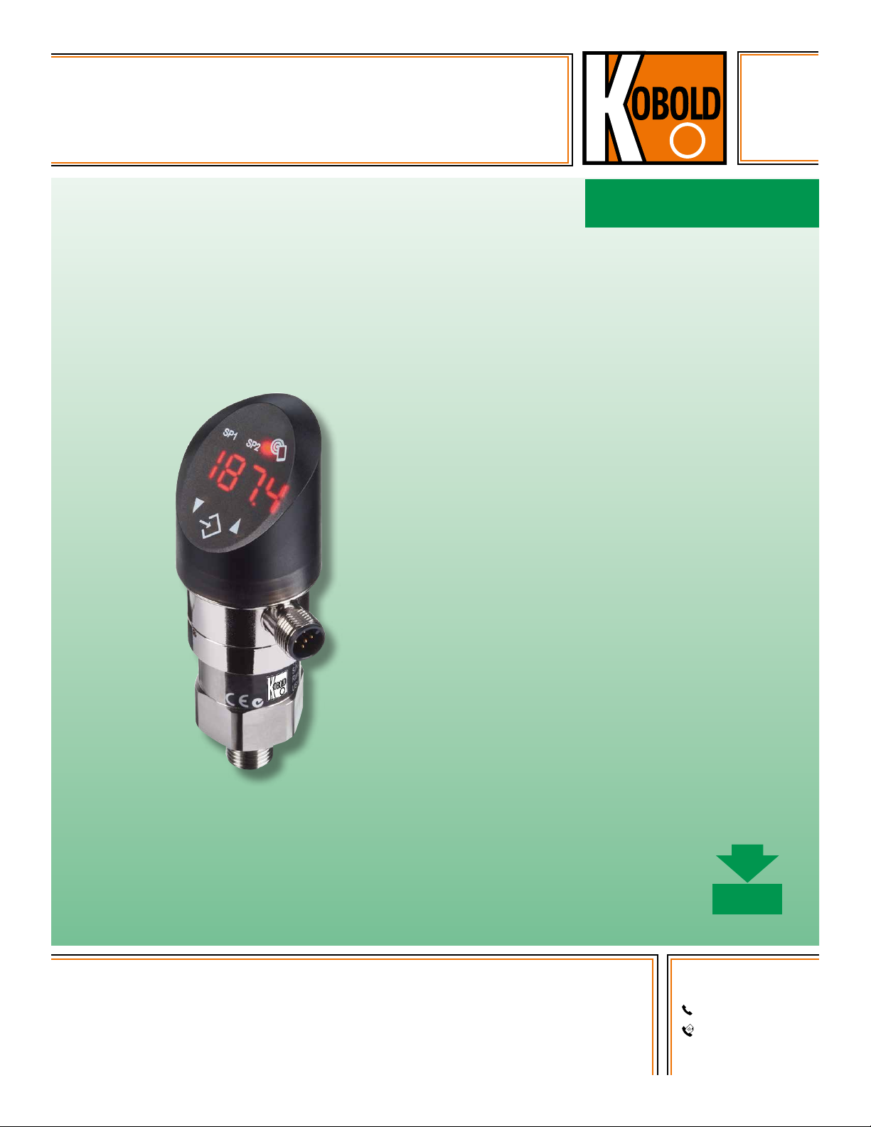
Digital Pressure Sensor Model PSD
Description
The economical PSD offers the ideal combination of two pressure
switches and a scalable transmitter output with a 45 degree
viewable, rotatable display. The parameters can be set directly
on the device. Within the settings, there are a comprehensive
set of options, making the PSD suitable for a wide range of
demanding applications. There is integral hysteresis, window,
and delay functionality included. OEM quantity pricing available
upon request.
Applications
• Machine Tools
• Hydraulics
• Process Technology
• Industrial Applications
• OEM Targeted Product
Technical Details
Measuring Principle: Thin Film
Measuring Range: 0...30 to 0... 7500 PSI,
Adjustable 50 ... 100 % FS
Output Signal: 4 ... 20 mA
0 ...10 VDC, Switchable mA or V
Switching Output: 2 PNP Transistors
Accuracy @ 77 °F typ.: ± 0.5 % FS typ.
Media Temperature: -13...185 °F
Ambient Temperature: -13...185 °F
Display Units: psi, bar, MPa, kPa, m WC,
mm WC
Electrical Data
Output/Supply Voltage: 4 ... 20 mA or 0-10 VDC /
24 (15 ... 30) V
DC
Switch-On Delay: typ. 200 ms
Inverse-polarity Protection,
Short-circuit Strength
@ 77 °F During 5 min.: Integrated
Current Consumption: ≤ 30 mA
Environmental Conditions
Media Temperature: -13...185 °F
Ambient Temperature: -13...185 °F
Protection1): IP65
Humidity: Max. 95 % Relative
Vibration: 10 g (10 ... 2000 Hz)
Shock: 50 g / 3 ms
1)
See »Electrical Connection«
Analog Output
Output Signal: 4-20 mA or 0-10 V
DC
Accuracy: TEB2) @ -13...185 °F
[% FS typ.] ± 1.75
Accuracy @ 77 °F
[% FS typ.] ± 0.5
NLH2) @ 77 °F (BSL2))
[% FS typ.] ± 0.2
TC2) Zero Point and Span
[% FS/K typ.] ± 0.03
Long Term Stability 1 Year
[% FS typ.] ± 0.1
Current Limiting
Output Signal: 4-20 mA: 25 mA (Overload)
0 ... 10 VDC: < 40 mA (Short-circuit)
Damping (Rise Time): 0.01 ... 3.00 s / 10 ... 90 %
Nominal Pressure
Switching Output
Accuracy: Accuracy @ 77 °F
[% FS typ.] ± 0.5
TEB2) @ -13...185 °F
[% FS typ.] ± 1.0
Long Term Stability 1 Year
[% FS typ.] ≤ ± 0.3
Adjustment Range of
Switchpoints: 0 … 100 % FS
Switching Hysteresis: ≥ 1 % FS Switchpoint > Reset Point
Switching Resistance: ≤ 3 Ω
Output Function: Hysteresis, Window; Normally
Closed (NC), Normally Open (NO)
Switching Current: ≤ 0.5 A Each Switching Output
Current Limiting: ≤ 2 A Each Switching Output
Switching Frequency: Max. 200 Hz
Delay Time: 0 ... 99.99 s
Display
Display: 4-Digit, 7-Segment Display, 180°
Flippable with Disable Function
Standard Decimal Places:
≤ 9: 3 Decimal Places
10 ... 99: 2 Decimal Places
100 ... 999: 1 Decimal Place
Switching Status
Indication: 2 LED, Red
Operation: with 3 Buttons and Menu
Navigation According to VDMA
24574-1
Display Resolution: 0.1 % FS
Display Range: -3 ... 103 % FS
Setting Parameters: See Parameter Table, pg 4
2)
See Terminology Section on page 6
2
www.koboldusa.com
No responsibility taken for errors;
subject to change without prior notice.
Page 3

Digital Pressure Sensor Model PSD
Accuracy (%)
5
0
Mechanical Data
Sensor (Wetted Parts): 1.4542 (AISI630)
Pressure Connection
(Wetted Parts): 1.4542 (AISI630)
Housing: Steel, Die Cast Metal Galvanized
Display Housing Plastic
Connection: 1/4" NPT
Male Electrical Plug: PA-plug M12x1.5-pin
Mounting Torque: 15 ... 20 Nm
Housing Alignment: Display 335° Rotatable,
Max. 2.5 Nm
Electrical Connection 343°
Rotatable, Max. 5 Nm
Surge Damping
Orifice: Ø 0.4 mm
Weight: ~189 g
Measuring Accuracy 0.5 %
4
3
2
1
0
-1
-2
-3
-4
-5
-30 -20 -10 0 10 20 30 40 50 60 70 80 9
Temperature (°C)
Total Error Band (TEB)
max. typ.
TEB (-25 ... +85°C)
(-25 ... +85 °C)
Overpressure and Burst Pressure
Range (PSI)
Overpressure
(PSI)
0..30 90 700
0...50 150 850
0...100 300 1450
0...150 450 2500
0...200 600 2500
0...300 900 4000
0...500 1500 4000
0...1000 3000 5000
0...1500 4500 7000
0...2000 6000 10000
0...3000 9000 14500
0...5000 12500 21750
0...7500 18750 29000
Burst Pressure
(PSI)
Order Details (Example: PSD-4 3 3 N2 P045)
Model Version
..4.. = 2 x PNP Switching
PSD-..
Output, Analog
Output 4-20 mA
or 0-10 V
DC
No responsibility taken for errors;
subject to change without prior notice.
Electrical
Connection
..3.. = M12 Plug,
24 (15-30)
V
DC
..3.. = Stainless
Material Connection Measuring Range Option
..P045 = 0...30 psi
..P055 = 0...50 psi
..P065 = 0...100 psi
..P075 = 0...150 psi
..P085 = 0...200 psi
..40 = Surge
Damping
Orifice
D = 0.4 mm
Steel
Connection
..N2.. = 1/4" NPT
Male
..P090 = 0...300 psi
..P100 = 0...500 psi
..P115 = 0...1000 psi
..P126 = 0...1500 psi
..P130 = 0...2000 psi
..P140 = 0...3000 psi
..P150 = 0...5000 psi
..P170 = 0...7500 psi
www.koboldusa.com
3
Page 4

Digital Pressure Sensor Model PSD
Accessories
Model Number Cable Length Description Number of Contacts
807.007 2 meters (6 feet) M12 Accessory Cable 5
807.007/5M 5 meters (16 feet) M12 Accessory Cable 5
807.007/10M 10 meters (32 feet) M12 Accessory Cable 5
ZUB-KAB-12D500 NA M12 box, screw connection 5
Parameter
Name Standard Setting Value Range
Switch Point SP1 (Hysteresis Mode)
Upper Switch Point FH1 (Window Mode)
Reset Point RP1 (Hysteresis Mode)
Lower Switch Point FL1 (Window Mode)
Switch Point SP2 (Hysteresis Mode)
Upper Switch Point FH2 (Window Mode)
Reset Point RP2 (Hysteresis Mode)
Lower Switch Point FL2 (Window Mode)
Switch Point Delay Time SP1 (Hysteresis Mode)
Switch Point Delay Time FH1 (Window Mode)
Switch Point Delay Time RP1 (Hysteresis Mode)
Switch Point Delay Time FL1 (Window Mode)
Switch Point Delay Time SP2 (Hysteresis Mode)
Switch Point Delay Time FH2 (Window Mode)
Switch Point Delay Time RP2 (Hysteresis Mode)
Switch Point Delay Time FL2 (Window Mode)
Functions Switching Output 1 Hysteresis, N/O (Hno)
Functions Switching Output 2 Hysteresis, N/O (Hno)
Pressure Units psi psi, bar, MPa, kPa, m WC uni
Measuring Range Adjustment 100 % Nominal Pressure 50 ... 100 % Nominal P-EP
Damping (Analog Output) 0.01 s 0.01 ... 3.00 s (Time Constant) dAA
Display Rotation No No, Yes (180°) disr
Display Mode Current Pressure Value
Display Update 2 1, 2, 5, 20 Hz duPd
75 % Measuring Range
25 % Measuring Range
75 % Measuring Range
25 % Measuring Range
0 0 ... 99.99 s dS1
0 0 ... 99.99 s dR1
0 0 ... 99.99 s dS2
0 0 ... 99.99 s dR2
Hysteresis NO (Hno), Hysteresis NC (Hnc),
Window NO (Fno), Window NC (Fnc)
Hysteresis NO (Hno), Hysteresis NC (Hnc)
Window NO (Fno), Window NC (Fnc)
Current, Highest, Lowest, Display Off
Decimal Places Selectable (Max. 3)
SP1 > RP1
FH1 > FL1
Hysteresis ≥ 1 % FS
RP1 < SP1
FL1 < FH1
Hysteresis ≥ 1 % FS
SP2 > RP2
FH2 > FL2
Hysteresis ≥ 1 % FS
RP2 < SP2
FL2 < FH2
Hysteresis ≥ 1 % FS
Pressure Value:
Current Value:
Short
Name
SP1
RP1
SP2
RP2
ou1
ou2
dis
4
www.koboldusa.com
No responsibility taken for errors;
subject to change without prior notice.
Page 5

Ø 37
t
P
ON
OFF
ON
OFF
Fno
Fnc
FL
FH
t
P
ON
Hno
OFF
ON
Hnc
OFF
rP
SP
t
P
ON
Hno
OFF
ON
Hnc
OFF
rP
SP
3
2
1
4
2
3
5
4
1
P
US+
US –
I
SP1, SP2
RL
US –
Earth
3
2
1
4
1
Dimensions (mm)
PSD
93
Digital Pressure Sensor Model PSD
335° max. 2.5 Nm
M12x1
343° max. 5 Nm
45.5
PSD- ... N2 ...
1/4" NPT
Ø 32
SW27 / Ø 29.5
48
Electrical Connection
Protection / Electrical Connection
IP65
M12x1
2
5-pole
3
5
4
Pin Assignment
P
FH
FL
Us+ = 1
Us- = 3
Output = 2
SP1 = 4
SP2 = 5
Shield
P
Earth
Connection of loads to
switching output
P
SP
rP
Us +
U
P
U / I
Out
Pin Configuration
Functions Switching Output
Hysteresis Window Delay
Out analogue
SP1
SP2
Shield
s
P
SP
rP
US+
US –
I
SP1, SP2
RL
US –
ON
OFF
ON
OFF
No responsibility taken for errors;
subject to change without prior notice.
t
Hno
Hnc
5
t
Hno
Hnc
ON
OFF
ON
OFF
www.koboldusa.com
Fno
Fnc
t
ON
OFF
ON
OFF
dS dr
Page 6

Terminology References
Digital Pressure Sensor Model PSD
BSL: Best Straight Line
The reference line according to the BSL or the minimum
value adjustment is placed in such a way that the
maximum positive and negative deviations are as small
as possible.
Specifications: Accuracy NLH (BSL)
Long-term Stability and Long-term Drift
The change of accuracy due to aging under certain
reference conditions during a period of time, typically
one year.
Non-linearity
The largest deviation from the effective characteristic
line of an ideal reference line. The reference line can
be defined as a limit point adjustment, a BSL, or a BSL
through 0.
Specifications: Non-linearity, Hysteresis
BSL/0: Best Straight Line through Zero
As an additional requirement for the minimum value
adjustment, the BSL through zero (also BSL/0) must go
straight through zero or the origin.
Specifications: Accuracy NLH (BSL through Zero)
NLH: Non-linearity and Hysteresis
Largest deviation from the ideal characteristic line
(BSL, BSL/0 or limit point). In pressure measuring
instruments, the non-linearity and pressure hysteresis
are given together at a constant temperature.
TEB: Total Error Band
Total error (root from sum of the square of the
deviations) due to measurement deviations (accuracy)
and temperature influence (temperature coefficient
TC). The temperature influence is usually given in the
information across a range larger than that given in the
standard (-10...60 °C).
TC: Temperature Coefficient
Change of measured value for zero point and span as a
result of changes in temperature.
6
www.koboldusa.com
No responsibility taken for errors;
subject to change without prior notice.
 Loading...