

Page 1
Operating Instructions
for
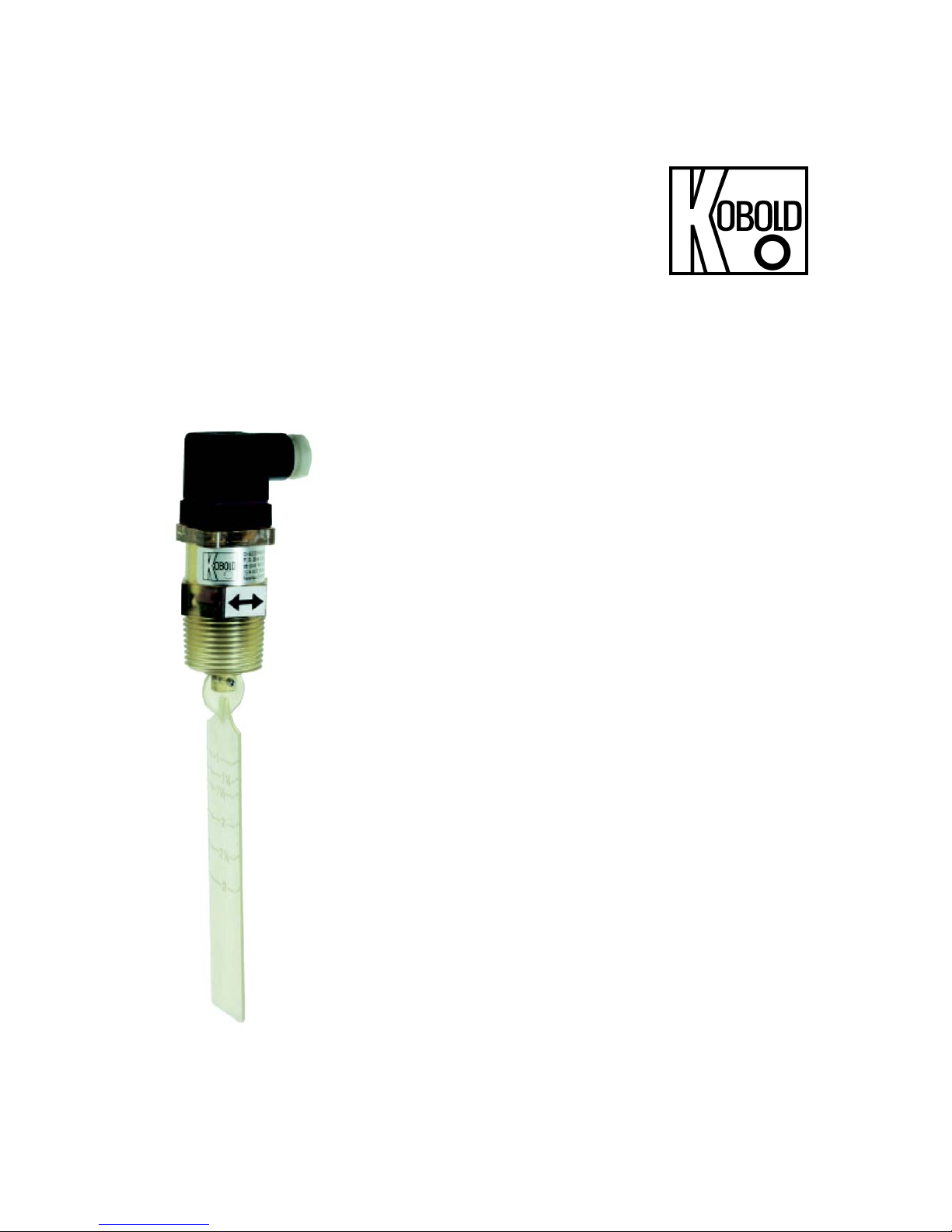
Polysulfone Paddle Monitor
Model: PPS-..
Page 2

PPS
page 2 PPS K02/0416
1. Contents
1.
Contents ........................................................................................................ 2
2. Note .............................................................................................................. 3
3. Regulation Use .............................................................................................. 3
4. Operating Principle ........................................................................................ 3
5. Instrument Inspection .................................................................................... 4
6. Mechanical Connection ................................................................................. 4
7. Electrical Connection .................................................................................... 6
8. Technical Information .................................................................................... 8
9. Order Codes ................................................................................................. 8
10.Maintenance ................................................................................................. 8
11.Recommended Spare Parts .......................................................................... 9
12.Dimensions ................................................................................................... 9
13.EU Declaration of Conformance .................................................................. 10
Manufactured and sold by:
Kobold Messring GmbH
Nordring 22-24
D-65719 Hofheim
Tel.: +49(0)6192-2990
Fax: +49(0)6192-23398
E-Mail: info.de@kobold.com
Internet: www.kobold.com
Page 3
PPS
PPS K02/0416 page 3
2. Note
Please read these operating instructions before unpacking and putting the unit
into operation. Follow the instructions precisely as described herein.
The devices are only to be used, maintained and serviced by persons familiar
with these operating instructions and in accordance with local regulations
applying to Health & Safety and prevention of accidents.
By usage in machines, the measuring unit should be used only when the
machines fulfil the EC-machine guidelines.
3. Regulation Use
The Model PPS-.. is installed for the purposes of monitoring flow throughputs of
liquids in nominal pipe sizes greater than NW 32. The paddle switch is available
with a factory set limit switch (N/O or N/C). It is suitable for low viscosity fluids
which have no effects on the instrument materials used. The flow throughput
switching point is determined by the length of the paddle. During installation the
paddle length may be reduced by cutting to adjust the set point.
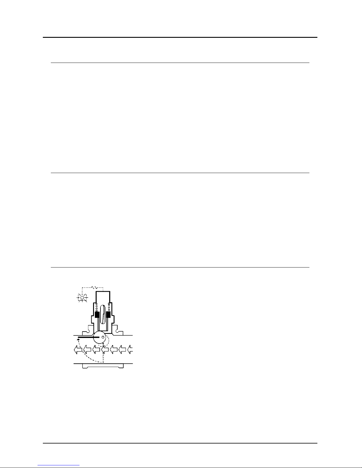
4. Operating Principle
Media flowing in any direction moves the paddle,
which rotates an eccentric, which in turn raises an
assembly within the unit. The assembly has a
permanent magnet mounted within it. This enables
the magnet to activate a hermetically sealed reed
switch. The signal from the reed switch can be used
to trigger an alarm or indicator. With the appropriate
relay, it is possible to automatically control pumps,
motors or valves.
Page 4

PPS
page 4 PPS K02/0416
5. Instrument Inspection
Instruments are inspected before shipping and sent out in perfect condition.
Should the damage to a device be visible, we recommend a thorough inspection
of the delivery packing. In case of damage, please inform your parcel service /
forwarding agent immediately, since they are responsible for damages during
transit.
Scope of delivery:
Paddle Monitor model: PPS
Operating Instructions
6. Mechanical Connection
Before installation:
Check the nominal pipe size and adapt by cutting at the paddle marking
according the following table the paddle monitor to your nominal pipe size and
the determined switching point.
Shorter paddle as specified in the table = higher switching point
Longer paddle as specified in the table = lower switching point
(Please note that the paddle length is not allowed to be longer than the
nominal pipe size).
Please ascertain whether the allowable maximum operating pressure and
operating temperature of the instruments will not be exceeded.
Remove all transport packing and ascertain that no packing material is left in
the instrument.
Nominal pipe size
(customer side)
Cutting mark (L)
approx. mm
Switching point
L/min rising
Switching point
L/min falling
32 28 36 18
40 35 54 36
50 47 72 36
65 60 90 54
80 73 108 72
Page 5

PPS
PPS K02/0416 page 5
Installation:
For mounting in a horizontal pipe line you need a vertical G 1" (1" NPT) socket.
Sealing of the connection threads should be carried out with Teflon tape or
similar. The paddle must be able to swing in the inner pipe and should not hit
against the inside wall of the sleeve. Therefore we recommend a max. length
of the socket of 20 mm.
Please take care that the broad dimension of the paddle has to show against
the flow direction. The arrow must show into the flow direction.
To reduce the influence of dirt we recommend to mount the instrument on the
top side of the pipe. This prevents a deposit of dirt. If a mounting on the top is
not possible, we recommend to check and to clean the instrument in regular
intervals (see maintenance).
If possible, check right after the mechanical installation that the connection
thread to the pipe is fully sealed.
Page 6

PPS
page 6 PPS K02/0416
7. Electrical Connection
Caution! Make sure that the voltage and current values of your
system correspond with the voltage values of the measuring unit
(see name plate). Possibly make shroud arrangements.
Make sure that the supply wires are de-energised.
Loosen the screw of the plug cap and remove the cap.
Connect the connection cable with the power supply
cable in accordance with the connection diagram
alongside.
Plug the plug on to the plug socket and tighten the
screw.
After connection of your external equipment at the connection points the
instrument is ready for operation.
1
2
1
2
1
3
2
Page 7

PPS
PPS K02/0416 page 7
Contact types
Model PPS-1201, Normally closed
The contact is opened when the flow increases and the set point value is
reached or exceeded. The switch closes again with falling flow at the minimum
value influenced by the switch hysteresis.
Model PPS-1202, Normally open
The contact is closed when the flow increases and the set point value is
reached or exceeded. The switch opens again with falling flow at the minimum
value influenced by the switch hysteresis.
Model PPS-1203 and model PPS-3203, changeover contact
The contact 1-2 is closed and the contact 1-3 is opened when the flow
increases and the set point value is reached or exceeded. The switch
backspaces again with falling flow at the minimum value influenced by the
switch hysteresis
Hysteresis
Defined as the difference between the opening and closing flow values of a
contact.
For example, the model PPS-1202 in tube with 11/4" ID, set at about 36 L/min
increasing set point will reset at about 18 L/min decreasing. Contact hysteresis =
18 L/min.
Contact protection
The reed contact may be damaged if the switch ratings are exceeded, especially
while switching inductive or capacitive loads. This can cause dangerous
situations. By the use of a contact protection relay, this problem can be overcome
and the lifespan and switch rating of the reed contact can be greatly increased.
(e. g. model MSR 10).
Page 8

PPS
page 8 PPS K02/0416
8. T echnical Information
Material housing / paddle: polysulfone, transparent
case: PSU or PTFE
spring: stainless steel 1.4310
safety pin: stainless steel 1.4305
magnet: oxide ceramic
Connection: G 1 (1“ NPT)
Medium temperature: max. 105 °C
Operating pressure: max. 10 bar
Max. pressure drop: max. 0,1 bar
Adjustment accuracy: ± 20%
Repeat accuracy: ± 3%
Other materials that
are exposed to the medium: stainless steel, ceramic magnet
Electrical connection: plug according to DIN 43 650
Protection: IP 65
Mounting Position: vertical
Switch: N/C, N/O or changeover contact
hermetically sealed reed-contact
Max. switching capacity: 230 V
AC/DC
; 2 A; 40 W / VA (N/O / N/C)
100 VDC;0,5 A; 5 W (changeover contact)
9. Order Codes
Contact operation
(with rising flow rate)
Order number
G 1 external thread
Order number
1 NPT external thread
N/C contact PPS-1201 PPS-3205
N/O contact PPS-1202 PPS-3202
changeover contact PPS-1203 PPS-3203
10. Maintenance
In cases where the flow medium is uncontaminated, the PPS will remain
maintenance-free. In particular, any ferritic particles present in the medium may
be deposited on the magnet, which can lead to problems. Large dirt particles can
lead to clamping of the paddle and of the magnet ring.
be deposited on the beam.
Depending on the amount of dirt present in the medium, we recommend that the
instrument is checked at regular intervals.
Page 9

PPS
PPS K02/0416 page 9
11. Recommended Spare Parts
1) Replacement paddle made of polysulfone
12. Dimensions
Page 10

PPS
page 10 PPS K02/0416
13. EU Declaration of Conformance
We, Kobold Messring GmbH, Hofheim-Ts, Germany, declare under our sole
responsibility that the product:
Polysulfone Paddle Monitor Model: PPS-..
to which this declaration relates is in conformity with the standards noted below:
EN 61010-1:2011
Safety requirements for electrical equipment for measurement, control and
laboratory use.
EN 60529:2014
Protection type through case (IP code)
Also the following EC guidelines are fulfilled:
2014/35/EU Low Voltage Directive
2011/65/EU RoHS (category 9)
Hofheim, 27. April 2016
H. Peters M. Wenzel
General Manager Proxy Holder
 Loading...