

Page 1
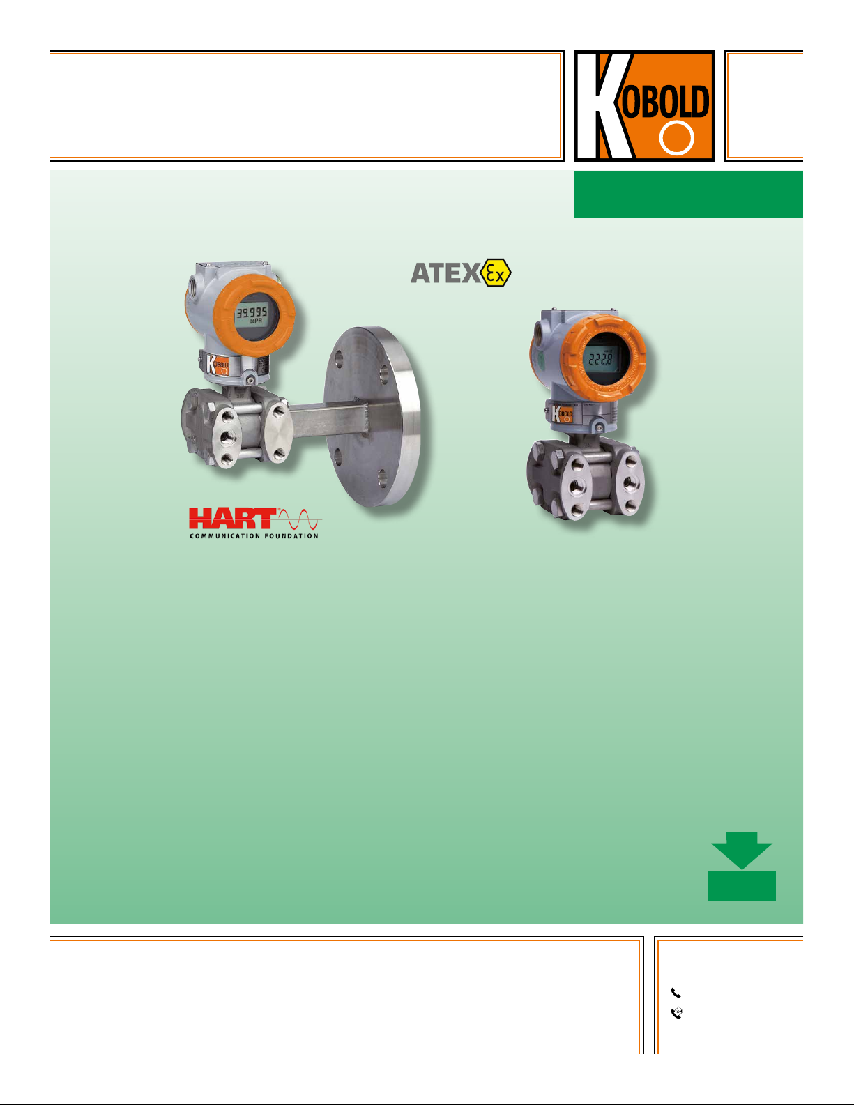
Heavy Duty
Differential Pressure
Transmitter
measuring
•
monitoring
•
analyzing
PAD
●● Span: 0.3" W.C. … 6" W.C. to 60 … 6000 PSIG
●● Static Pressure: Max. 4500 PSIG
●● t
: 248 °F
max
●● Process Connection: ½" NPT, ¼" NPT, or Various
Diaphragm Seals Available upon Request
●● Material: Stainless Steel
●● Various Outputs: 4 ... 20 mA or Frequency Output
●● Sensor Inputs: Differential, Gauge, or Absolute Pressure
●● Digital Communication with HART
KOBOLD companies worldwide:
ARGENTINA, AUSTRALIA, AUSTRIA, BELGIUM, BULGARIA, CANADA, CHILE, CHINA, COLOMBIA,
CZECH REPUBLIC, EGYPT, FRANCE, GERMANY, HUNGARY, INDIA, INDONESIA, ITALY, MALAYSIA,
MEXICO, NETHERLANDS, PERU, POLAND, REPUBLIC OF KOREA, ROMANIA, SINGAPORE, SPAIN,
SWITZERLAND, TAIWAN, THAILAND, TUNISIA, TURKEY, UNITED KINGDOM, USA, VIETNAM
01/03-18-2019
®
Protocol
KOBOLD Instruments, Inc.
1801 Parkway View Drive
Pittsburgh, PA 15205
Main Ofce:
1.412.788.2830
1.412.788.4890
info@koboldusa.com
www.koboldusa.com
Page 2
Heavy Duty Differential Pressure Transmitter Model PAD
Description
The KOBOLD Differential Pressure Transmitter model PAD
is a microprocessor based high performance transmitter.
It has flexible pressure calibration and output, automatic
compensation of ambient temperature and process variables,
configuration of various parameters, and communication with
HART® protocol. It measures pressure, flow and level by an
application method. All data is input, modified and stored in
EEPROM.
The KOBOLD Pressure Transmitter is also available as a flow
meter. The flowmeter model PAD-F has an added totalizing
function. It is able to check the flow rate and the totalizing flow.
It measures the flow rate by using differential pressure without
compensation for the temperature and static pressure. The
shape of the PAD-F is the same as the standard device.
Only the terminal block is different, since there are two more
terminals for the display of the pulse output.
Features
Superior Performance
●● High Reference Accuracy
●● Long-term Stability (0.125 % URL for 3 Years)
●● High Rangeability (100:1) for Range 4-0
Flexibility
●● Data Configuration with HART
●● Zero Point Adjustment
®
Communicator
Reliability
●● Continuous Self-diagnostic Function
●● Automatic Ambient Temperature Compensation
●● EEPROM Write Protection
●● Fail-mode Process Function
●● CE EMC Conformity Standards (EN 50081-2, EN 50082-2)
Transmitter Description
Electronics module
The Electronics module consists of a circuit board sealed in
an enclosure. There is an MCU module. an analog module,
an LCD module and a terminal module within the transmitter.
The MCU module acquires the digital value from the analog
module and applies correction coefficients selected from
EEPROM. The output section of the MCU module converts
the digital signal to a 4…20 mA output. The MCU module
communicates with the HART®-based communicator or
control system such as DCS. The power section of the MCU
module has a DC-to-DC power conversion circuit and an
input/output isolation circuit. The LCD module plugs into
the MCU module and displays the digital output in a userconfigured unit.
Functional Block Diagram
High
Pressure
User-Selectable Input
• - D /- G /- H /- A
• Measuring Range
2
Sensor Part MCU Part
A/D Conversion
Capacitive
Sensor
EEPROM
Low
Pressure
Microprocessor
· Input Sensor Value
· Engineering Units
· Re–range (Zero / Span)
· Sensor Trimming
· Zero Point Adjustment
· DA Trimming
· Damping / Filtering
· Transfer Function
· LCD Engineering Mode
· Diagnostics
· Self Compensation
· Communications
· LCD Display
· Configuration Data
www.koboldusa.com
4~20mA
DAC
®
HART
HART® Protocol
with Host
No responsibility taken for errors;
subject to change without prior notice.
Page 3
Heavy Duty Differential Pressure Transmitter Model PAD
Sensor Inputs
The models PAD-D, PAD-G, and PAD-H are available in a
capacitance type differential pressure sensor. It measures
differential and gauge pressure and is commonly used in flow
and level applications. Both sides in the capacitance sensor
transmit process pressure from the process isolators to the
sensor. The model PAD-A is also available in a piezoresistive
type absolute pressure sensor. The sensor module converts
the capacitance or the resistance to the digital value. The
MCU module calculates the process pressure based on the
digital value.
The sensor modules include the following features
• The software of the transmitter compensates thermal
effects, improving performance.
• Precise Input Compensation during operation is achieved
with temperature and pressure correction coefficients that
are characterized over the range of the transmitter and
stored in the sensor module EEPROM memory.
• EEPROM stores sensor information and correction
coefficients separately from MCU module, allowing for easy
repair, reconfiguration and replacement.
Basic Setups
The following settings can be easily configured from any host
that supports the HART® protocol:
• Operational Parameters
• 4-20 mA Points (Zero/Span)
• Engineering Units
• Damping Time: 0.25...60 sec
• Tag: 8 Alphanumeric Characters
• Descriptor: 16 Characters
• Message: 32 Characters
• Date: Day/Month/Year
Self-Diagnosis and others
• CPU & Analog Module Fault Detection
• Communication Error
• Fail-mode Handling
• LCD Indication
• Temperature Measurement of Sensor Module
Multi Planar Process Connection
When the pressure transmitter should be vertically installed irrespective
of the orientation of the process connection lines, modified flanges
(as shown above) are required in addition to the basic flanges. Multiplanar pressure transmitters have been made in an effort to solve
the problems occurring in these types of installation. The object of
this is to provide a pressure transmitter, capable of being vertically
installed, without separate adapters or various types of brackets.
This is regardless of the position of the process connection lines.
Calibration and Adjustment
• Lower/Upper Range (Zero/Span)
• Sensor Zero Trimming
• Zero Point Adjustment
• DAC Output Trimming
• Transfer Function
• Self-Compensation
No responsibility taken for errors;
subject to change without prior notice.
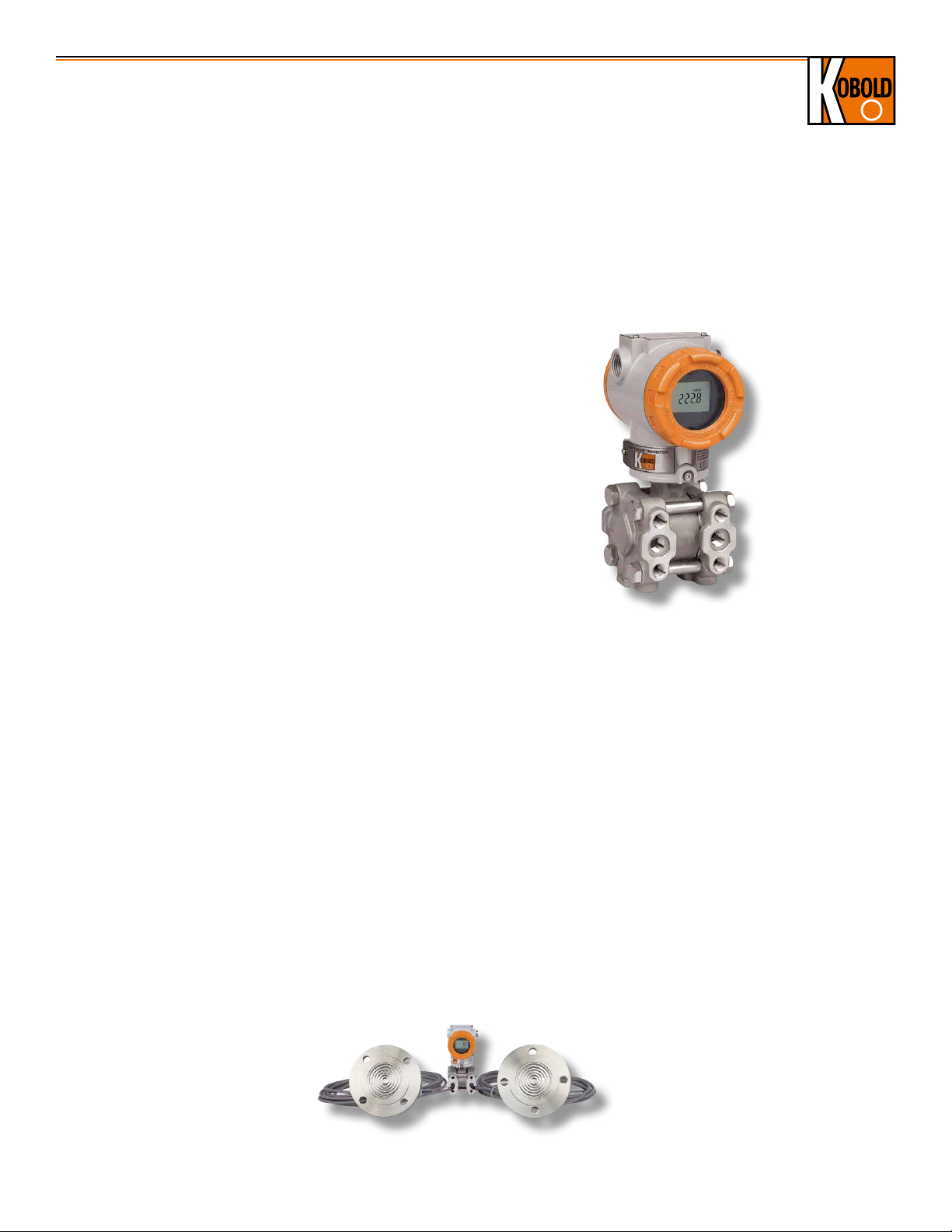
Process Connection Via Diaphragm Seals
When connecting the differential pressure transmitter model PAD to
all different process connections, diverse diaphragm seal versions
are necessary. They can be connected to the differential pressure
transmitter by direct mounting or via a capillary tube. Depending on
the application, different combinations of diaphragm seals, capillary
tubes and fill fluids are available. To clarify those options, the special
connections via diaphragm seals should be specified separately for
the differential pressure transmitter.
www.koboldusa.com
3
Page 4

Heavy Duty Differential Pressure Transmitter Model PAD
Technical Details
Measuring Principle: Capacitance Sensor (PAD-D, -F, -G, -H)
Piezo-resistive (PAD-A)
Measuring Span: 0.3" W.C..6" W.C. to 60…6,000 PSIG
bar (Depending on Instrument Version)
Zero and Span Values can be set
anywhere within the Range Limits.
Span must be Greater than or Equal
to the Minimum Span.
Accuracy
Range 2: ±0.25 % of Span for
0.1 URL ≤ Span ≤ URL
±[0.24 + (0.008 x (URL/Span)) % of
Span for 0.05 URL ≤ Span ≤0.1 URL
Range 3: ±0.075 % of Span for
0.1 URL ≤ Span ≤ URL
±[0.25 + (0.005 x (URL/span))] % of
Span for 0.02 URL ≤ Span ≤0.1 URL
Range 4 to 0: ±0.075 % of Span for
0.1 URL ≤ Span ≤ URL
±[0.025+(0.005x(URL/Span))] % of
Span for 0.01 URL ≤ Span ≤0.1 URL
Stability: ± 0.125% URL for 36 Months
Static Press. Effect: ± 0.1% URL per 70 bar (Zero Error)
± 0.2% of Reading per 70 bar (Span Error)
Turndown Ratio: Ranges 4 ~ 0 = 100 : 1
Range 3 = 50 : 1
Range 2 = 20 : 1
Process Temp.: -40…248 °F
(Approval Codes may Affect Limits.
Max. Ambient Temperature at
LCD = 176 °F.)
Ambient Temp.: -22…176 °F
Ambient Temp.
Effect: ± (0.019% URL + 0.125% Span) /28 °C
Storage Temp.: -40…185 °F (Non-condensing)
Humidity Limit: 5 %...100 % RH
Power Supply Effect: ± 0.005% of span per Volt
Mounting Pos. Effect: Zero Shift up to 350 Pa, no span effect
Pressure Limits (with Silicone Oil)
(Valid for stand-alone instruments only without assembled
diaphragm seals.)
Model D and G: 0…1999.6 PSIG (for Range 2...8)
Model G: 0…5800 PSIG (for Range 9)
0...10875 PSIG (for Range 0)
Model H: 0…4495 PSIG (for Range 4...7)
Model A: 0…72.5 PSIG (for Range 4)
0…435 PSIG (for Range 5)
0…754 PSIG (for Range 6)
Burst Pressure
Model D, G and H: 9990.5 PSIG
11600 PSIG (for Model G, Range 0)
Model A: 145 PSIG (for Range 4)
580 PSIG (for Range 5)
1015 PSIG (for Range 6)
4
Wetted Materials
Isolating Diaphragms: 316L SS
Drain/Vent Valves: 316 SS
Flanges/Adapters: 316 SS
O-ring: FKM, PTFE as an Option
Non-Wetted Materials
Fill Fluid: Silicone Oil
Bolts: Stainless Steel
Housing: Aluminum or SS, Flameproof (Ex d) and
Waterproof (lP67)
Cover O-ring: NBR
Paint: Epoxy-polyester or Polyurethane
Mounting Bracket: For 2-inch Pipe, 304 SS,
with 304 SS U-bolt
Nameplate: 304 SS
Process
Connections: ¼" NPT with 54.0 mm Center
Distance for Standard Flanges,
½" NPT with Process Adapter
(Option)
Mount Position: Upright (Process Connection more
Flexible by using Multi-planar Flange)
Display: 5 Digit LCD
Power Supply: 12…45 VDC
17.5…45 VDC -HART® Communication
Maximum Load: 250 Ω at 17.5 VDC
550 Ω at 24 V
Max. Loop Resistance =
Loop Load: 0...1500 Ω - Operation
250...550 Ω - HART® Communication
Failure Mode: Fail High: Current ≥ 21.1 mA
Fail Low: Current ≤ 3.78 mA
Electrical
Connection: ½" NPT Conduit with M4 Screw
Terminals (G½ Option)
Output: • Two Wire 4…20 mA, Configurable
for Linear or Square Root Output, Digital
Process Value Superimposed on
4…20 mA Signal, Available to any Host
that Conforms to the HART® Protocol
• Frequency Output for Flowmeter
Model PAD-F with Pulse Width of 10,
50 or 100 ms (Selectable, Negative
Going Pulse)
Output Type: Open Collector, 30 V,
500 mA max.
Pulse Rate: 49 pulses/sec max.
Turn-On Time: 3 seconds
Protection: IP 67 for Standard (Code S)
Weight: 8.6 lb (Excluding Options) Standard
11.8 lb (SS Housing - Excl. Options)
ATEX Approval
(Option): II 2G Exd IIC T6 ... T5
II 1G or 2G Ex ia IIC T5 or
T4 Ga or Gb
www.koboldusa.com
DC
(U - 12 VDC)
0.022 A
No responsibility taken for errors;
subject to change without prior notice.
Page 5

Heavy Duty Differential Pressure Transmitter Model PAD
Order Details (Example: PAD-D EE 2 S 2 N S 0 0)
Model Version
..D.. = Differential Pressure Transmitter
(Static Pressure 2000 PSI)
..F..1) = Differential Pressure Transmitter with
Pulse Output and Totalizer for
PAD-
Flow Measurement
..H.. = Differential Pressure Transmitter for High
Line Pressure (Static Pressure 4495 PSI)
..G.. = Gauge Pressure Transmitter
..A.. = Absolute Pressure Transmitter
Material
Body/Vent Plug/
Diaphragm
..EE.. = 316 SS / 316 SS / 316L SS
Calibrated Span
(Measuring Range Limits for PAD-D,
-F, -G and -H in Separate Table)
Calibrated Span for
PAD-D, -F, -G, -H
..2..3) = 0.3"...6" W.C.
..3.. = 0.6"...30" W.C.
..4.. = 1.5"...150" W.C.
..5.. = 7.5"...750" W.C.
..6.. = 1...100 PSIG
..7.. = 3...300 PSIG
..8..3) = 10 ...1000 PSIG
3)4)
..9..
..0..
= 30...3000 PSIG
3)4)
= 60...6000 PSIG
Calibrated Span for PAD-A
..4.. = 10"...1000" W.C.
..5.. = 1.5...217 PSIA
..6.. = 3...362 PSIA
Order Details Continued
Fill Liquid Process Connection
..S.. = Silicone
1)
Specify flow rate engineering unit, ∆ p and flow rate
at URV (Upper Range Value), ∆ p and flow rate (generally '0')
at LRV (Lower Range Value)
pulse scale (choose only one value from
0.001, 0.01, 0.1, 1, 10, 100, 1 000, 10 000 m³/pulse) and
pulse width (choose only one value from
10 ms, 50 ms, 100 ms), while ordering so that max.
duty cycle is 49 pulses/sec
..2..6) = ¼" NPT
Female
Electrical
Connection
..N.. = ½" NPT
Epoxy Polyester
Painted
Aluminum
..G.. =G ½ Epoxy Polyester
Painted
Aluminum
Approvals Options
..S0.. = Standard
(Waterproof
IP67)
..F0.. = ATEX,
Flameproof, Ex d
..E0.. = ATEX,
Intrinsically Safe, Ex i
3)
Not for PAD-H
4)
Not for PAD-D and PAD-F
5)
Diaphragm seal model and application data to be specified in clear text.
The online application guide on the PAD product page of the website must be
completed for any PAD ordered with a DRM. For summary of
diaphragm seal models and possible ranges, see page 11 onwards. For
dimensional details see DRM data sheet.
6)
1/2" NPT connection via an adapter is available, see page 6
..0 = without
..C = Engineering Unit (must be
chosen when using the
differential transmitter as a
flowmeter)
..D = PTFE O-ring (Wetted Part)
..E = Oil Free Finish
..F = Side Vent / Drain Bottom
..G = Side Vent / Drain Top
..H = Multi-Planar
Process Connection
..M = Housing in Stainless Steel
..N5) = Mounting of PAD onto
Diaphragm Seal
No responsibility taken for errors;
subject to change without prior notice.
www.koboldusa.com
5
Page 6
Heavy Duty Differential Pressure Transmitter Model PAD
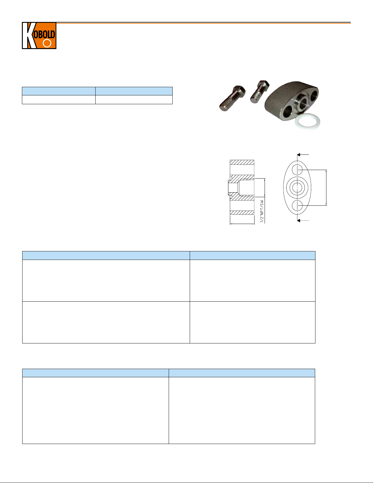
Order Details: Oval Flange Adapter
Description Order Number
1/2" NPT Oval Flange Adapter
ZUB-PAD-OVF
Technical Details
Material: 316 Stainless Steel
Seal: PTFE
Bolts: 2 x Mounting Screws 7/16"-20 UNF
Connection: ½" NPT Female
Dimensions
1.63"
Order Details: Mounting Brackets
Description Order Number
Angle Type Bracket for PAD/PAS
Vertical Pipe Mounting for PAS
Vertical Pipe Mounting for PAD
Incl. U-Clamp for 2“ Pipe Mounting Bracket and 2 x Mounting Nuts/Washers
Incl. 4 x Mounting Screws for PAS
Incl. 4 x Mounting Screws for PAD
Flat Type Bracket for PAD/PAS
Horizontal Pipe Mounting for PAS
Vertical Pipe Mounting for PAD
Incl. U-Clamp for 2“ Pipe Mounting Bracket and Mounting Nuts/Washers
Incl. 4 x Mounting Bolts and Washers for PAS
Incl. 4 x Mounting Bolts for PAD
Order Details: Manifold Valves
Description Order Number
3-way Manifold Valve, Remote Mount, Machined
5-way Manifold Valve, Remote Mount, Machined
2-way Manifold Valve, Direct Mount, Machined
2-way Compact Manifold Valve, Direct Mount, Machined
3-way Compact Manifold Valve, Direct Mount, Machined
5-way Compact Manifold Valve, Direct Mount, Machined
3-way Manifold Valve, Direct Mount, Forged
0.98"
ZUB-PAD/PAS-K
ZUB-PAD/PAS-L
ZUB-PAD-3WMR
ZUB-PAD-5WMR
ZUB-PAD-2WMD
V-2003CDADABAA
V-3151CHHHIBAA
V-5050CDAHIBAA
V-3454CHHHHBAA
6
www.koboldusa.com
No responsibility taken for errors;
subject to change without prior notice.
Page 7
Heavy Duty Differential Pressure Transmitter Model PAD
Measuring Range Limits for PAD-D, -F, -G and -H
Range Code Calibrated Span
PAD-D, -F PAD-G PAD-H
Lower Range Limit (LRL)
Upper Range Limit (URL)
2 0.3...6" W.C. -6" W.C. -6" W.C. - 6" W.C.
3 0.6...30" W.C. -30" W.C. -30" W.C. - 30" W.C.
4 1.5...150" W.C. -150" W.C. -150" W.C. -150" W.C. 150" W.C.
5 7.5...750" W.C. -750" W.C. -14.5 PSIG -750" W.C. 750" W.C.
6 1...100 PSIG -100 PSIG -14.5 PSIG -100 PSIG 100 PSIG
7 3...300 PSIG -300 PSIG -14.5 PSIG -300 PSIG 300 PSIG
8 10...1000 PSIG -1000 PSIG -14.5 PSIG - 1000 PSIG
9 30...3000 PSIG - -14.5 PSIG - 3000 PSIG
0 60...6000 PSIG - -14.5 PSIG - 6000 PSIG
* Special measuring span, with adequate lower and upper range limits, on request.
Range Code Unit Conversion
Range Code bar kg/cm² KPa psi in H2O at 39 °F
2 0.015 0.015 1.5 0.217 6 152 0.422
3 0.075 0.076 7.5 1.087 30 765 2.215
4 0.373 0.38 37.3 5.410 149 3804 11.014
5 1.865 1.902 186.5 27 749 19018 55.072
6 6.900 7.036 690 100 2773 70361 203.750
7 20.681 21.088 2068 300 8310 210878 610.660
8 68.950 70.309 6895 1000 27708 703097 2036.025
9 206.800 210.876 20680 3000 83105 2108781 6106.597
0 413.700 421.856 41370 6000 166085 4218566 12216.550
mm H2O at
39 °F
in Hg at 32 °F
No responsibility taken for errors;
subject to change without prior notice.
www.koboldusa.com
7
Page 8

Dimensions
LOCK
LOCK
FIELD
TERMINALS
s
112
73 39
79.5
113
192.5
LOCK
LOCK
FIELD
TERMINALS
s
316
CF8MXXXX
112
73 39
89.5
113
202.5
LOCK
LOCK
FIELD
TERMINALS
s
316
CF8MXXXX
112
122
324.5
210
PAD Standard*
Heavy Duty Differential Pressure Transmitter Model PAD
PAD Multi-Planar Process Connection*
4.41"*/4.69"**
112
2.87"*/3.15"**
1.54"
73 39
s
TERMINALS
FIELD
LOCK
LOCK
* For Ex d and Standard
113
4.45"
79.5
3.13"
7.58"
192.5
42
1.65"
E
N
E
E
L
G
R
I
H
D
E
Z
I
W
N
E
3.39"
86
U
A
C
-
P
O
T
O
54
2.13"
T
I
O
N
D
O
N
-
I
N
E
X
P
L
O
S
I
V
E
A
T
M
O
S
P
H
E
R
E
7/16-20 UNF
** For Ex i
PAD with Multi-Planar Flange and Angle Type Bracket*
3.39"
R
E
N
E
E
L
I
D
E
Z
I
G
H
W
N
E
86
U
A
C
-
P
O
T
O
N
4.33"
110
T
I
O
N
-
I
N
E
X
P
L
O
S
I
V
E
A
T
M
O
S
P
H
E
R
E
D
O
* For Ex d and Standard
** For Ex i
4.41"*/4.69"**
112
s
LOCK
TERMINALS
FIELD
LOCK
CF8MXXXX
316
122
4.80"
324.5
12.78"
4.41"*/4.69"**
112
2.87"*/3.15"**
1.54"
73 39
s
TERMINALS
FIELD
LOCK
LOCK
CF8MXXXX
316
* For Ex d and Standard
113
4.45"
89.5
3.52"
202.5
7.97"
42
1.65"
E
N
E
E
L
R
I
H
D
E
Z
I
G
W
N
E
3.39"
86
U
A
C
-
P
O
T
O
54
2.13"
T
I
O
N
-
I
N
E
X
P
L
O
S
I
V
E
A
T
M
O
S
P
H
E
R
E
D
O
N
** For Ex i
PAD Standard with Flat Type Bracket (Vertically Mounted)*
4.41"*/4.69"**
112
s
LOCK
TERMINALS
FIELD
LOCK
323.5
12.74"
G
R
E
N
E
E
L
I
H
3.39"
D
E
Z
I
W
N
E
P
3.70"
86
I
T
O
U
N
A
-
C
-
I
N
E
X
P
L
O
S
I
V
E
A
T
M
O
S
P
H
E
R
O
E
T
D
O
O
N
* For Ex d and Standard
** For Ex i
94
47
1.85"
210
8.27"
PAD Standard with Flat Type Bracket (Horizontally Mounted)*
8.27"
4.72"
120
I
T
O
U
N
A
-
C
-
I
N
D
E
E
X
Z
I
P
L
G
O
R
S
E
I
N
V
E
E
E
A
* For PAD-G/A, the low pressure port 'L' is always closed
8
L
I
T
M
H
W
O
S
N
P
H
E
E
P
R
O
E
T
D
O
O
N
www.koboldusa.com
4.41"*/4.69"**
112
s
TERMINALS
FIELD
LOCK
LOCK
* For Ex d and Standard
** For Ex i
205.5
8.09"
47
1.85"
No responsibility taken for errors;
subject to change without prior notice.
Page 9

Static
Process side Block valve Sied
Block valve
Equalize valve
Flow schematic
Technical Specications:
Material: 316SS
Connection & Size: ½" NPT (F)
Pressure rating: 6,000 psig at 38°C (≈410 bar)
Heavy Duty Differential Pressure Transmitter Model PAD
Process side Block valve Sied
Block valve
Equalize valve
Flow schematic
228.0 (open, approx.)
Process side
Instrument side
Block valve
½" NPT
4 places
¼" NPT
Static vent
2 places
Block valve
44.0
Ø 7.0 DIA
Mounting holes
2 places
side
24.0
54.0
86.0
31.0
Technical Specications:
Material: 316SS
Connection & Size: ½" NPT (F)
Pressure rating: 6,000 psig at 38°C (≈410 bar)
Temperature range: -54°C ... +232°C
Weight: 2 kg
Technical Specications:
Material: 316SS
Connection & Size: ½" NPT (F)
Pressure rating: 6,000 psig at 38°C (≈410 bar)
Temperature range: -54°C ... +232°C
Weight: 2.2 kg
Process side
Instrument side
228.0 (open, approx.)
Block valve
86.0
43.0
24.0
Instrument Instrument
Process Vent port Process
Static
(test)
Static
(test)
Equalize Equalize
Block/
Isolate
Block/
Isolate
Flow schematic
Vent
Instrument Instrument
Process Vent port Process
Static
(test)
Static
(test)
Equalize Equalize
Block/
Isolate
Block/
Isolate
Flow schematic
Vent
PAD-G/A Mounted with 2-way Manifold Valve*
3.39"
4.41"*/4.69"**
4.80"
* For PAD-G/A, the low pressure port 'L' is always closed.
Manifold Valves (Remotely Mounted)
Technical Specifications
Material: 316 SS Body with PTFE Packing
Connection: ½" NPT (F)
Pressure Rating: 6000 PSIG at 100 °F (≈410 bar)
Temperature Range: -65...449 °F
* For Ex d and Standard
** For Ex i
7.58"
3-way Manifold Valve
Equalize valve
104.5 (open, approx.)
4.11"
33.3
1.31"
5-way Manifold Valve
Equalize valve Equalize valve
85.0 (open, approx.)
3.35
No responsibility taken for errors;
subject to change without prior notice.
¼" NPT
Static port
2 places
3.07"
78.0
Bleed valve
2.13"
54.0
¼" NPT
Vent port
½" NPT
4 Places
33.3
1.31"
Block valve
Ø 7.0 DIA
0.28"
Mounting holes
2 places
side
Process side
228.0 (open, approx.)
8.98"
½" NPT
4 places
Block valve
www.koboldusa.com
1.22"
31.0
24.0
0.95"
Instrument side
8.98"
8.98"
228.0 (open, approx.)
1.73"
44.0
3.39"
86.0
1.69"
43.0
0.95"
24.0
Process side
Block valve
Instrument side
54.0
2.13"
¼" NPT
Static vent
2 places
86.0
3.39"
Block valve
Block valve
Equalize valve
Process side Block valve Sied
Instrument
side
Weight: 4.41 lbs
Instrument Instrument
Equalize Equalize
Static
(test)
Block/
Isolate
Vent
Block/
Isolate
Process Vent port Process
Weight: 4.85 lbs
(test)
9
Page 10

Heavy Duty Differential Pressure Transmitter Model PAD
Vent
Bleed
Block
Process
1/4" NPT vent port
28.4
47.8
7.8
41.4
16
Bleed valve
50.8
50.8
92.60 (open)
Instrument
Vent
Bleed
Block
Process
Instrument
Manifold Valves (Direct Mount)
Technical Specifications:
Material: 316 SS Body with PTFE Packing
Pressure Rating: 3000 PSIG at 449 °F (≈210 bar)
Connection: ½" NPT (F) to Flange
Temperature Range: -65...449 °F
2-way Manifold Valve
1.77"
Block valve
45
1/4" NPT vent port
28.4
1.12"
47.8
1.88"
2.00"
50.8
Vent
Instrument side
0.48"
Ø 12.2 for
7/16" bolts
63.5 (open)
2.50"
31
1.22"
41.3
1.63"
3.81"
96.8
1/2" NPT
2 places
Process side
92.60 (open)
3.65"
41.4
1.63"
7.8
16
0.63" 0.31"
Bleed valve
50.8
2.00"
Bleed
Instrument
Weight: 3.53 lbs
Block
Process
10
www.koboldusa.com
No responsibility taken for errors;
subject to change without prior notice.
Page 11

Heavy Duty Differential Pressure Transmitter Model PAD
IN
Drain
Manifold Valves (Direct Mount, Machined)
Technical Details
Material: AISI 316L
Pressure Rating: 6 000 psi
Temperature Range: -99...410 °F (PTFE Packing), Standard
-65... 950 °F (GRAPHOIL Packing), On Request
Weight: 1.94 lbs
2-way Manifold Valve: V-2003CDADABAA (PTFE Packing)
(Inlet: ½" NPT Female / Outlet: ½" NPT Male)
VENT.
5.83"
148
IS
O
A
L
E
T
4.73"
120
OUT IN
30
1.18"
Ø
Drain
IN
Included Accessories: Plug
No responsibility taken for errors;
subject to change without prior notice.
Drain 1/4" NPT-F with plug
www.koboldusa.com
11
Page 12

Heavy Duty Differential Pressure Transmitter Model PAD
ND
OUT
32
Ø
12
IN
IN
D
IN
P
DRAINDRAIN
E
QU
A
L
I
S
E
Flanged Type
IEC 61518/A
70
OUT
41.4
32
124
54
224
N°4 fori Ø12
IN
106
IN
D
IN
P
DRAINDRAIN
84
DRAIN 1/4" NPT-F
EQUALISE
ISOLATE
ISOLATE
E
QU
A
L
I
S
E
30
N°2 fixing
holes M10
Flanged Type
IEC 61518/A
70
Manifold Valves (Direct Mount, Machined)
Technical Details
Material: AISI 316L
Pressure Rating: 6 000 psi
Temperature Range: -99...410 °F (PTFE Packing), Standard
-65...950 °F (GRAPHOIL Packing), On Request
Weight: 4.78 lbs
3-way Manifold Valve: V-3151CHHHIBAA (PTFE Packing)
(Inlet: Flanged / Outlet: Flanged According to IEC 61518 Type B / Type A)
8.82"
N°4 holes
Ø12
4.88"
2.76"
DRAI
D
P
RAIN
IN
IN
1.18"
2.13"
3.31"
4.17"
Included Accessories:
4 Carbon Steel Screws (Stainless Steel On Request)
2 Plugs
2 PTFE Gaskets
Mounting Options 3-way Manifold Valve with PAD
Description Process Connection Illustration
Valve Mounted Upside Down on Front Side of PAD Flanged According to IEC 61518 Type A
Valve Mounted Upside Down on Front Side of PAD
including Oval Flange Adapter Model ZUB-PAD-OVF
1.26"
½" NPT Female
7/16"-20 UNF
2¾"
1/4" NPT
7/16" UNF
Valve Mounted on Front Side of PAD, Head of PAD
Rotated 90° Clockwise
Valve Mounted on Front Side of PAD including Oval
Flange Adapter Model ZUB-PAD-OVF, Head of PAD
Rotated 90° Clockwise
12
Flanged According to IEC 61518 Type A
½" NPT Female
www.koboldusa.com
No responsibility taken for errors;
subject to change without prior notice.
Page 13

Heavy Duty Differential Pressure Transmitter Model PAD
IN
32
70
IN
DRAIN 1/4" NPT-F
DRAIN DRAIN
142
41.4
54
N°2 fixing holes M10
D
P
260
IN
ISOLATE
VENT. EQUALISE VENT.
ISOLATE
V
E
N
T
.
30
102
10.5
16
Ø
12 holes
OUT
Flanged Type
IEC 61518/A
IN
32
70
IN
T-F
DRAIN DRAIN
D
P
IN
V
E
N
T
.
30
102
10.5
16
OUT
Flanged Type
IEC 61518/A
IN
IN
DRAIN DRAIN
D
P
IN
IN
DRAIN DRAIN
D
P
Manifold Valves (Direct Mount, Machined)
Technical Details
Material: AISI 316L
Pressure Rating: 6 000 psi
Temperature Range: -99...410 °F (PTFE Packing), Standard
-65...950 °F (GRAPHOIL Packing), On Request
Weight: 6.17 lbs
5-way Manifold valve: V-5050CDAHIBAA (PTFE Packing)
(Inlet: ½" NPT / Outlet: Flanged According to IEC 61518 Type A)
10.24"
260
VENT. EQUALISE VENT.
124
4.88"
ISOLATE
ISOLATE
41.4
D
P
IN
1.18"
4.02"
30
102
IN
16
0.63"
DRAIN DRAIN
0.41"
10.5
Flanged Type
IEC 61518/A
OUT
70
2.76"
V
E
N
T
.
IN
N°4 Ø12 holes
N°4 12 holesN°4 12 holes
Included Accessories:
4 Carbon Steel Screws (Stainless Steel On Request)
2 Plugs
2 PTFE Gaskets
Mounting Options for 5-way Manifold Valve with PAD
Valve Mounted Upside Down on Front Side of PAD ½" NPT Female
Valve Mounted on Front Side of PAD after Rotating
the Head of PAD 90° Clockwise
Description Process Connection Illustration
2.13"
54
5.59"
142
DRAIN 1/4" NP
N°2 fixing holes M10
½" NPT Female
1.26"
32
7/16"-20 UNF
1/4" NPT
1¾"
7/16" UNF
No responsibility taken for errors;
subject to change without prior notice.
www.koboldusa.com
13
Page 14

Heavy Duty Differential Pressure Transmitter Model PAD
IN
32
70
IN
DRAIN 1/4" NPT-F
DRAIN DRAIN
142
41.4
54
N°2 fixing holes M10
D
P
260
IN
ISOLATE
V
E
N
T
.
30
102
10.5
16
OUT
Flanged Type
IEC 61518/A
Manifold Valves (Direct Mount, Forged)
Technical Details
Material: 316L Stainless Steel
Pressure Rating: 6 000 psi
Temperature Range: -99...410 °F (PTFE Packing), Standard
-65...950 °F (GRAPHOIL Packing), On Request
Weight: 4.96 lbs
3-way Manifold Valve: V-3454CHHHHBAA (PTFE Packing)
(Inlet: Flanged Oval/ Outlet: Flanged According to IEC 61518 Type B)
0.51"
0.81" ± 0.004"
2.13" ± 0.01"
7.68"
3.39"
1.63" ± 0.008"
3.98"
4.41"
2.13"
0.47"
1.63" ± 0.008"
3.66"
2.09"
0.81" ± 0.004"
Included Accessories:
4 Carbon Steel Screws (Stainless Steel On Request)
2 PTFE Gaskets
14
www.koboldusa.com
7/16" UNF
1¾"
No responsibility taken for errors;
subject to change without prior notice.
7/16"-20 UNF
Page 15

Heavy Duty Differential Pressure Transmitter Model PAD
Δ L (min. 150 mm max. 500 mm)
welded
Example of PAD Direct Assembed with an Extended Diaphragm Seal (not available as ATEX-Version)
(for Dimensional Details, see DRM Data Sheet)
Fig. 1
Dimensions: Examples for DN50 / DN 80/DN100 / 2" ANSI / 3" ANSI/4"ANSI
Flange Type D k d
2
b f d
DN50 PN16 6.50" 4.92" 0.71" 0.71" 0.08"
DN50 PN40 6.50" 4.92" 0.71" 0.79" 0.08" 0.16" 1.89"
2" ANSI Cl. 150 6.00" 4.75" 0.75" 0.75" 0.08"
2" ANSI Cl. 300 6.50" 5.00" 0.75" 0.88" 0.08" 0.31" 1.89"
DN80 PN16 7.87" 6.30" 0.71" 0.79" 0.08"
DN80 PN40 7.87" 6.30" 0.71" 0.94" 0.08" 0.31" 2.99"
3" ANSI Cl. 150 7.50" 6.00" 0.75" 0.94" 0.06"
3" ANSI Cl. 300 8.25" 6.63" 0.87" 1.12" 0.06" 0.31" 2.99"
DN100 PN16 8.66" 7.09" 0.71" 0.79" 0.08" 5.87" 0.31" 3.50"
DN100 PN40 9.25" 7.48" 0.87" 0.94" 0.08" 5.87" 0.31" 3.50"
4" ANSI Cl. 150 9.00" 7.50" 0.75" 0.94" 0.06" 6.19" 0.31" 3.50"
4" ANSI Cl. 300 10.00" 7.87" 0.87" 1.26" 0.06" 6.19" 0.31" 3.50"
4
4.02"
3.62"
5.43"
5.00"
X d
0.16" 1.89"
0.16" 1.89"
0.31" 2.99"
0.16" 2.99"
5
100 mm (4")/
150 mm (6")/
200 mm (8")/
R
L
50 mm (2")/
(customer
specified)
Example of PAD Assembed with Remote Diaphragm Seals and Capillaries
(for Dimensional Details, see DRM Data Sheet)
Dimensions: Examples for DN50 / DN 80 /DN100 / 2" ANSI / 3" ANSI/4"ANSI
Flange Type D k d
DN50 PN16 6.50" 4.92" 0.71" 0.71" 0.08"
DN50 PN40 6.50" 4.92" 0.71" 0.79" 0.08" 0.16"
2" ANSI Cl. 150 6.00" 4.75" 0.75" 0.75" 0.08"
2" ANSI Cl. 300 6.50" 5.00" 0.75" 0.88" 0.08" 0.31"
DN80 PN16 7.87" 6.30" 0.71" 0.79" 0.08"
DN80 PN40 7.87" 6.30" 0.71" 0.94" 0.08" 0.31"
3" ANSI Cl. 150 7.50" 6.00" 0.75" 0.94" 0.06"
3" ANSI Cl. 300 8.25" 6.63" 0.87" 1.12" 0.06" 0.31"
DN100 PN16 8.66" 7.09" 0.71" 0.79" 0.08" 5.87" 0.31"
DN100 PN40 9.25" 7.48" 0.87" 0.94" 0.08" 5.87" 0.31"
4" ANSI Cl. 150 9.00" 7.50" 0.75" 0.94" 0.06" 6.19" 0.31"
4" ANSI Cl. 300 10.00" 7.87" 0.87" 1.26" 0.06" 6.19" 0.31"
Fig. 2
No responsibility taken for errors;
subject to change without prior notice.
www.koboldusa.com
2
b f d
4.02"
3.62"
5.43"
5.00"
4
X
0.16"
0.16"
0.31"
0.16"
15
Page 16

Heavy Duty Differential Pressure Transmitter Model PAD
Example of PAD-G Remote Assembled with (Extended) Diaphragm Seal and Capillary
(for Dimensional Details, see DRM Data Sheet)
Fig. 3
Dimensions: Examples for DN50 / DN 80 /DN100 / 2" ANSI / 3" ANSI/4"ANSI
Flange Type D k d
2
b f d
DN50 PN16 6.50" 4.92" 0.71" 0.71" 0.08"
DN50 PN40 6.50" 4.92" 0.71" 0.79" 0.08" 0.16" 1.89"
2" ANSI Cl. 150 6.00" 4.75" 0.75" 0.75" 0.08"
2" ANSI Cl. 300 6.50" 5.00" 0.75" 0.88" 0.08" 0.31" 1.89"
DN80 PN16 7.87" 6.30" 0.71" 0.79" 0.08"
DN80 PN40 7.87" 6.30" 0.71" 0.94" 0.08" 0.31" 2.99"
3" ANSI Cl. 150 7.50" 6.00" 0.75" 0.94" 0.06"
3" ANSI Cl. 300 8.25" 6.63" 0.87" 1.12" 0.06" 0.31" 2.99"
DN100 PN16 8.66" 7.09" 0.71" 0.79" 0.08" 5.87" 0.31" 3.50"
4
4.02"
3.62"
5.43"
5.00"
X d
0.16" 1.89"
0.16" 1.89"
0.31" 2.99"
0.16" 2.99"
5
R
L
50 mm (2")/
100 mm (4")/
150 mm (6")/
200 mm (8")/
(customer
specified)
DN100 PN40 9.25" 7.48" 0.87" 0.94" 0.08" 5.87" 0.31" 3.50"
4" ANSI Cl. 150 9.00" 7.50" 0.75" 0.94" 0.06" 6.19" 0.31" 3.50"
4" ANSI Cl. 300 10.00" 7.87" 0.87" 1.26" 0.06" 6.19" 0.31" 3.50"
16
www.koboldusa.com
No responsibility taken for errors;
subject to change without prior notice.
Page 17

Heavy Duty Differential Pressure Transmitter Model PAD
Diaphragm Seal Models (Remote Assembly)
(Standard device without additional options (e.g. coatings, special materials etc.).
For dimensions/technical data, see DRM data sheet. Accuracy: 0.075% of calibrated span + influence of seal).
Over and under ranges of the min./max. span may be possible, but must be verified by KOBOLD for each application.
The indicated min./max. spans do not consider any coating of diaphragm seals. For additional information contact KOBOLD.
Model DRM Size Code Size Note
DRM-601 R15 G ½
R20 G ¾ Ø 23.8 0 ... 36.3 14500
R25 G 1 Ø 29.5 0 ... 23.2 8700
R32 G 1 ¼ Ø 38 0 ...14.5 8700
DRM-603
DIN 11851
DRM-605
IDF
R40 G 1 ½ Ø 40 0 ...14.5 8700
N15 ½" NPT Ø 18 0 ... 87 14500
N20 ¾" NPT Ø 18 0 ... 87 14500
N25 1" NPT Ø 23.8 0 ... 36.3 8700
N32 1 ¼" NPT Ø 34.5 0 ... 23.2 8700
M20 M20 x 1.5 Ø 18 0 ... 87 8700
M48 M 48 x 3 Ø 40 0 ...14.5 8700
R20 DN 20
R25 DN 25 Ø 23.8 0 ... 36.3 580
R32 DN 32 Ø 29.5 0 ... 23.2 580
R40 DN 40 Ø 38 0 ...14.5 580
R50 DN 50 Ø 45.5 0 ... 8.7 362.5
R65 DN 65 Ø 64 0 ... 5.8 362.5
R80 DN 80 Ø 64 0 ... 5.8 362.5
R1H DN 100 Ø 64 0 ... 5.8 362.5
R25 1"
R40 1 ½" Ø 42 0 ... 14.5 580
R50 2" Ø 56 0 ... 8.7 580
Fixed Male Thread with
Capillary
Dairy Connection, Capillary
IDF Socket with Union Nut,
Capillary
Ø Diaphragm
(mm)
Ø 18
Ø 18
Ø 29.5
Max. Media
Temperature
392 °F
392 °F
392 °F
Min. Span
(PSIG)
0 ... 87 14500
0 ... 87 580
0 ... 23.2 580
Max. Span
(PSIG)
DRM-606
R20 G ¾
Capsule Seal with Rotable
Male, Capillary
R28 M 28 x 1,5 0 ...145 8700
DRM-608/1
DRM-611
SMS
* Note: Threaded diaphragm seal only available with PAD-G/A. For PAD-D only flange, clamp connections or union nut are possible
No responsibility taken for errors;
subject to change without prior notice.
R20 G ¾
R25 G 1
R40 1 ½"
R50 2" Ø 45.5 0 ... 8.7 580
Capsule Seal with Union Nut,
Capillary
Capsule Seal with Union Nut,
Capillary
SMS Socket with Union Nut,
Capillary
www.koboldusa.com
Short capsule 662 °F
Long capsule
662 °F
Long capsule 0 ... 23.2 8700
Ø 34.5
392 °F
0 ...145 8700
0 ... 23.2 8700
0 ... 23.2 580
17
Page 18

Heavy Duty Differential Pressure Transmitter Model PAD
Diaphragm Seal Models (Remote Assembly)
(Standard device without additional options (e.g. coatings, special materials etc.).
For dimensions/technical data, see DRM data sheet. Accuracy: 0.075% of calibrated span + influence of diaphragm seal).
Model DRM Size Code Size Note
DRM-613
Clamp
R25 1"
F40 1 ½" Ø 35.5 0 ...23.2 232
Ø Diaphragm
(mm)
Ø 18
Max. Media
Temperature
Min. Span
(PSIG)
0 ...87 232
Max. Span
(PSIG)
DRM-615
APV-RJT
DRM-617
DRM-620
DRM-620/1
F50 2" Ø 45.5 0 ...8.7 232
R65 2 ½" Ø 52 0 ...8.7 232
R80 3" Ø 64 0 ...5.8 145
R20 1"
R40 1 ½" Ø 42.5 0 ... 14.5 1450
R50 2" Ø 56 0 ... 8.7 1450
R45 M 45 x 2 Union-nut, Capillary Ø 23.8 248 °F 0 ... 36.3 23200
R20 G ¾ Union-nut, Capillary Ø 23.8 662 °F 0 ... 36.3 8700
R20 G ¾ Union-nut, capillary Ø 23.8 662 °F 0 ... 36.3 8700
Tri-Clamp, Capillary
Ø 29.5
Union-nut, Capillary
392 °F
0 ... 36.3 1450
392 °F
DRM-622/1
DRM-624/1
DRM-625/1
* Note: Threaded diaphragm seal only available with PAD-G/A. For PAD-D only flange, clamp connections or union nut are possible
18
F48 Ø 48 mm
F48 1 Ø 48 mm Ø 48 0 ...8.7 580
F48 2 Ø 48 mm Ø 48 0 ...8.7 580
F1H Ø 100 mm Flange, Capillary Ø 63.5 482 °F 0 ... 5.8 580
R15 G ½
N15 ½" NPT 0 ... 5.8 580
I15 G ½ male 0 ... 5.8 580
Flange, Capillary
Fixed male, Capillary Ø 63.5 482 °F
www.koboldusa.com
Ø 48
392 °F
0 ...8.7 580
0 ... 5.8 580
No responsibility taken for errors;
subject to change without prior notice.
Page 19

Heavy Duty Differential Pressure Transmitter Model PAD
Diaphragm Seal Models (Direct or Remote Assembly)
(Standard device without additional options (e.g. coatings, special materials etc.).
For dimensions/technical data, see DRM data sheet. Accuracy: 0.075% of calibrated span + influence of diaphragm seal).
Model DRM Size Code Size Note
DRM-627
PN 25
DRM-627
PN 100
DRM-627
PN 250
R08A025 G ¼ male Fixed Male, Capillary Ø 56
R08I025 G ¼ female Fixed Female, Capillary Ø 56 0 ... 8.7 362.5
R15A025 G ½ male Fixed Male, Capillary Ø 56 0 ... 8.7 362.5
R15I025 G ½ female Fixed Female, Capillary Ø 56 0 ... 8.7 362.5
N15A025 ½" NPT male Fixed Male, Capillary Ø 56 0 ... 8.7 362.5
R08A100 G ¼ male Fixed Male, Capillary Ø 56
R08I100 G ¼ female Fixed Female, Capillary Ø 56 0 ... 8.7 1450
R15A100 G ½ male Fixed Male, Capillary Ø 56 0 ... 8.7 1450
R15I100 G ½ female Fixed Female, Capillary Ø 56 0 ... 8.7 1450
N15A100 ½" NPT male Fixed Male, Capillary Ø 56 0 ... 8.7 1450
R08A250 G ¼ male Fixed Male, Capillary Ø 56
R08I250 G ¼ female Fixed Female, Capillary Ø 56 0 ... 8.7 3625
R15A250 G ½ male Fixed Male, Capillary Ø 56 0 ... 8.7 3625
R15I250 G ½ female Fixed Female, Capillary Ø 56 0 ... 8.7 3625
N15A250 ½" NPT male Fixed Male, Capillary Ø 56 0 ... 8.7 3625
Ø Diaphragm
(mm)
Max. Media
Temperature
482 °F
482 °F
482 °F
Min. Span
(PSIG)
0 ... 8.7 362.5
0 ... 8.7 1450
0 ... 8.7 3625
Max. Span
(PSIG)
DRM-629
PN 06
DRM-629
PN 16
DRM-629
PN 40
DRM-630/1
PVC
F25P06 DN 25
F32P06 DN 32 Ø 30 0 ... 36.3 87
F40P06 DN 40 Ø 38 0 ... 14.5 87
F50P06 DN 50 Ø 48 0 ... 8.7 87
F65P06 DN 65 Ø 64 0 ... 5.8 87
F80P06 DN 80 Ø 64 0 ... 5.8 87
F1HP06 DN 100 Ø 64 0 ... 5.8 87
F25P16 DN 25
F32P16 DN 32 Ø 30 0 ... 36.3 232
F40P16 DN 40 Ø 38 0 ... 14.5 232
F50P16 DN 50 Ø 48 0 ... 8.7 232
F65P16 DN 65 Ø 64 0 ... 5.8 232
F80P16 DN 80 Ø 64 0 ... 5.8 232
F1HP16 DN 100 Ø 64 0 ... 5.8 232
F25P40 DN 25
F32P40 DN 32 Ø 30 0 ... 36.3 580
F40P40 DN 40 Ø 38 0 ... 14.5 580
F50P40 DN 50 Ø 48 0 ... 8.7 580
F65P40 DN 65 Ø 64 0 ... 5.8 580
F80P40 DN 80 Ø 64 0 ... 5.8 580
F1HP40 DN 100 Ø 64 0 ... 5.8 580
R08 G ¼ female
R15 G ½ female Ø 64 0 ... 5.8 145
N15 ½" NPT female Ø 64 0 ... 5.8 145
Flange to EN1092-1,
Capillary
Flange to EN1092-1,
Capillary
Flange to EN1092-1,
Capillary
Fixed Female, Capillary
Ø 24
Ø 24
Ø 24
Ø 64
0 ... 36.3 87
482 °F
0 ... 36.3 232
482 °F
0 ... 36.3 580
482 °F
0 ... 5.8 145
104 °F
DRM-631/1
PP
DRM-632/1
PVDF
* Note: Threaded diaphragm seal only available with PAD-G/A. For PAD-D only flange, clamp connections or union nut are possible
No responsibility taken for errors;
subject to change without prior notice.
R08 G ¼ female
R15 G ½ female Ø 64 0 ... 5.8 145
N15 ½" NPT female Ø 64 0 ... 5.8 145
R08 G ¼ female
R15 G ½ female Ø 64 0 ... 5.8 232
N15 ½" NPT female Ø 64 0 ... 5.8 232
Fixed Female, Capillary
Fixed Female, Capillary
www.koboldusa.com
Ø 64
104 °F
Ø 64
122 °F
0 ... 5.8 145
0 ... 5.8 232
19
Page 20

Heavy Duty Differential Pressure Transmitter Model PAD
Diaphragm Seal Models (Direct or Remote Assembly)
(Standard device without additional options (e.g. coatings, special materials etc.).
For dimensions/technical data, see DRM data sheet. Accuracy: 0.075% of calibrated span + influence of diaphragm seal).
Model DRM Size Code Size Note
DRM-633/1
F50 DN 50
F1H DN 100 Ø 64 0 ... 3.6 580
Flange to DIN2527 Form C,
Capillary
Ø Diaphragm
(mm)
Ø 64
Max. Media
Temperature
482 °F
Min. Span
(PSIG)
0 ... 3.6 580
Max. Span
(PSIG)
DRM-635
150 lbs
DRM-635
300 lbs
DRM-635
600 lbs
DRM-635
1500 lbs
A25P150 1"
A32P150 1¼" Ø 38 0 ... 14.5 145
A40P150 1 ½" Ø 38 0 ... 14.5 145
A50P150 2" Ø 48 0 ... 8.7 145
A65P150 2 ½" Ø 48 0 ... 8.7 145
A80P150 3" Ø 64 0 ... 5.8 145
A90P150 3 ½" Ø 64 0 ... 5.8 145
A1HP150 4" Ø 64 0 ... 5.8 145
A25P300 1"
A32P300 1¼" Ø 38 0 ... 14.5 290
A40P300 1 ½" Ø 38 0 ... 14.5 290
A50P300 2" Ø 48 0 ... 8.7 290
A65P300 2 ½" Ø 48 0 ... 8.7 290
A80P300 3" Ø 64 0 ... 5.8 290
A90P300 3 ½" Ø 64 0 ... 5.8 290
A1HP300 4" Ø 64 0 ... 5.8 290
A25P600 1"
A32P600 1¼" Ø 38 0 ... 14.5 580
A40P600 1 ½" Ø 38 0 ... 14.5 580
A50P600 2" Ø 48 0 ... 8.7 580
A65P600 2 ½" Ø 48 0 ... 8.7 580
A80P600 3" Ø 64 0 ... 5.8 580
A90P600 3 ½" Ø 64 0 ... 5.8 580
A1HP600 4" Ø 64 0 ... 5.8 580
A25P1K5 1"
A32P1K5 1¼" Ø 38 0 ... 14.5 1450
A40P1K5 1 ½" Ø 38 0 ... 14.5 1450
A50P1K5 2" Ø 48 0 ... 8.7 1450
A65P1K5 2 ½" Ø 48 0 ... 8.7 1450
A80P1K5 3" Ø 64 0 ... 5.8 1450
A90P1K5 3 ½" Ø 64 0 ... 5.8 1450
A1HP1K5 4" Ø 64 0 ... 5.8 1450
Flange to ASME B16.5,
Capillary
Flange to ASME B16.5,
Capillary
Flange to ASME B16.5,
Capillary
Flange to ASME B16.5,
Capillary
Ø 30
Ø 30
Ø 30
Ø 30
0 ... 36.3 145
482 °F
0 ... 36.3 290
482 °F
0 ... 36.3 580
482 °F
0 ... 36.3 1450
482 °F
DRM-638
PN 06
DRM-638
PN 16
* Note: Threaded diaphragm seal only available with PAD-G/A. For PAD-D only flange, clamp connections or union nut are possible
20
F25P06 DN25
F32P06 DN32 Ø 30 0 ... 14.5 87
F40P06 DN40 Ø 38 0 ... 14.5 87
F50P06 DN50 Ø 48 0 ... 8.7 87
F65P06 DN65 Ø 64 0 ... 8.7 87
F80P06 DN80 Ø 64 0 ... 5.8 87
F1HP06 DN100 Ø 64 0 ... 5.8 87
F25P16 DN25
F32P16 DN32 Ø 38 0 ... 14.5 232
F40P16 DN40 Ø 38 0 ... 14.5 232
F50P16 DN50 Ø 48 0 ... 8.7 232
F65P16 DN65 Ø 48 0 ... 8.7 232
F80P16 DN80 Ø 64 0 ... 5.8 232
F1HP16 DN100 Ø 64 0 ... 5.8 232
Flange to EN1092-1,
Capillary
Flange to EN1092-1,
Capillary
www.koboldusa.com
Ø 24
482 °F
Ø 24
482 °F
0 ... 36.3 87
0 ... 36.3 232
No responsibility taken for errors;
subject to change without prior notice.
Page 21

Heavy Duty Differential Pressure Transmitter Model PAD
Diaphragm Seal Models (Direct or Remote Assembly)
(Standard device without additional options (e.g. coatings, special materials etc.).
For dimensions/technical data, see DRM data sheet. Accuracy: 0.075% of calibrated span + influence of diaphragm seal).
Model DRM Size Code Size Note
DRM-638
PN 40
DRM-640
150 lbs
DRM-640
300 lbs
DRM-640
600 lbs
DRM-640
1500 lbs
* Note: Threaded diaphragm seal only available with PAD-G/A. For PAD-D only flange, clamp connections or union nut are possible
F25P40 DN 25
F32P40 DN 32 Ø 38 0 ... 14.5 580
F40P40 DN 40 Ø 38 0 ... 14.5 580
F50P40 DN 50 Ø 48 0 ... 8.7 580
F65P40 DN 65 Ø 48 0 ... 8.7 580
F80P40 DN 80 Ø 64 0 ... 5.8 580
F1HP40 DN 100 Ø 64 0 ... 5.8 580
A25P150 1"
A32P150 1¼" Ø 38 0 ... 14.5 145
A40P150 1 ½" Ø 38 0 ... 14.5 145
A50P150 2" Ø 48 0 ... 8.7 145
A63P150 2 ½" Ø 48 0 ... 8.7 145
A75P150 3" Ø 64 0 ... 5.8 145
A85P150 3 ½" Ø 64 0 ... 5.8 145
A1HP150 4" Ø 64 0 ... 5.8 145
A25P300 1"
A32P300 1¼" Ø 38 0 ... 14.5 290
A40P300 1 ½" Ø 38 0 ... 14.5 290
A50P300 2" Ø 48 0 ... 8.7 290
A63P300 2 ½" Ø 48 0 ... 8.7 290
A75P300 3" Ø 64 0 ... 5.8 290
A85P300 3 ½" Ø 64 0 ... 5.8 290
A1HP300 4" Ø 64 0 ... 5.8 290
A25P600 1"
A32P600 1¼" Ø 38 0 ... 14.5 580
A40P600 1 ½" Ø 38 0 ... 14.5 580
A50P600 2" Ø 48 0 ... 8.7 580
A63P600 2 ½" Ø 48 0 ...8.7 580
A75P600 3" Ø 64 0 ... 5.8 580
A85P600 3 ½" Ø 64 0 ... 5.8 580
A1HP600 4" Ø 64 0 ... 5.8 580
A25P1K5 1"
A32P1K5 1¼" Ø 38 0 ... 14.5 1450
A40P1K5 1 ½" Ø 38 0 ... 14.5 1450
A50P1K5 2" Ø 48 0 ... 8.7 1450
A63P1K5 2 ½" Ø 48 0 ... 8.7 1450
A75P1K5 3" Ø 64 0 ... 5.8 1450
A1HP1K5 4" Ø 64 0 ... 5.8 1450
Flange to EN1092-1,
Capillary
Flange to ASME B16.5,
Capillary
Flange to ASME B16.5,
Capillary
Flange to ASME B16.5,
Capillary
Flange to ASME B16.5,
Capillary
Ø Diaphragm
(mm)
Ø 30
Ø 30
Ø 30
Ø 30
Ø 30
Max. Media
Temperature
482 °F
482 °F
482 °F
482 °F
482 °F
Min. Span
0 ... 36.3 580
0 ... 36.3 145
0 ... 36.3 290
0 ... 36.3 580
0 ... 36.3 1450
(PSIG)
Max. Span
(PSIG)
No responsibility taken for errors;
subject to change without prior notice.
www.koboldusa.com
21
Page 22

Heavy Duty Differential Pressure Transmitter Model PAD
Diaphragm Seal Models (Direct or Remote Assembly)
(Standard device without additional options (e.g. coatings, special materials etc.).
For dimensions/technical data, see DRM data sheet. Accuracy: 0.075% of calibrated span + influence of diaphragm seal).
Model DRM Size Code Size Note
DRM 501
ISO Sterile
DRM 503
Clamp
ISO 2852
* Note: Threaded diaphragm seal only available with PAD-G/A. For PAD-D only flange, clamp connections or union nut are possible
D15 DN 15
D20
D25 DN 25 Inline 0 ... 14.5 580
D32 DN 32 Inline 0 ... 14.5 580
D40 DN 40 Inline 0 ... 8.7 580
D50 DN 50 Inline 0 ... 8.7 580
D15
D20 DN 20 Inline 0 ... 23.2 580
D25 DN 25 Inline 0 ... 8.7 580
D32 DN 32 Inline 0 ... 8.7 580
D40 DN 40 Inline 0 ... 5.8 580
D50 DN 50 Inline 0 ... 5.8 580
DN 20
Inline, Capillary
DN 15
Inline, Capillary
Ø Diaphragm
(mm)
Inline
Inline 0 ... 36.3 580
Inline
Max. Media
Temperature
176 °F
176 °F
Min. Span
(PSIG)
0 ... 36.3 580
0 ... 23.2 580
Max. Span
(PSIG)
22
www.koboldusa.com
No responsibility taken for errors;
subject to change without prior notice.
 Loading...