

Kobold OPT Series, OPT-..10 Series, OPT-...22 Series, OPT-...22/...N4 Series, OPT-4 Series Operating Instructions Manual
...Page 1
Operating Instructions
for
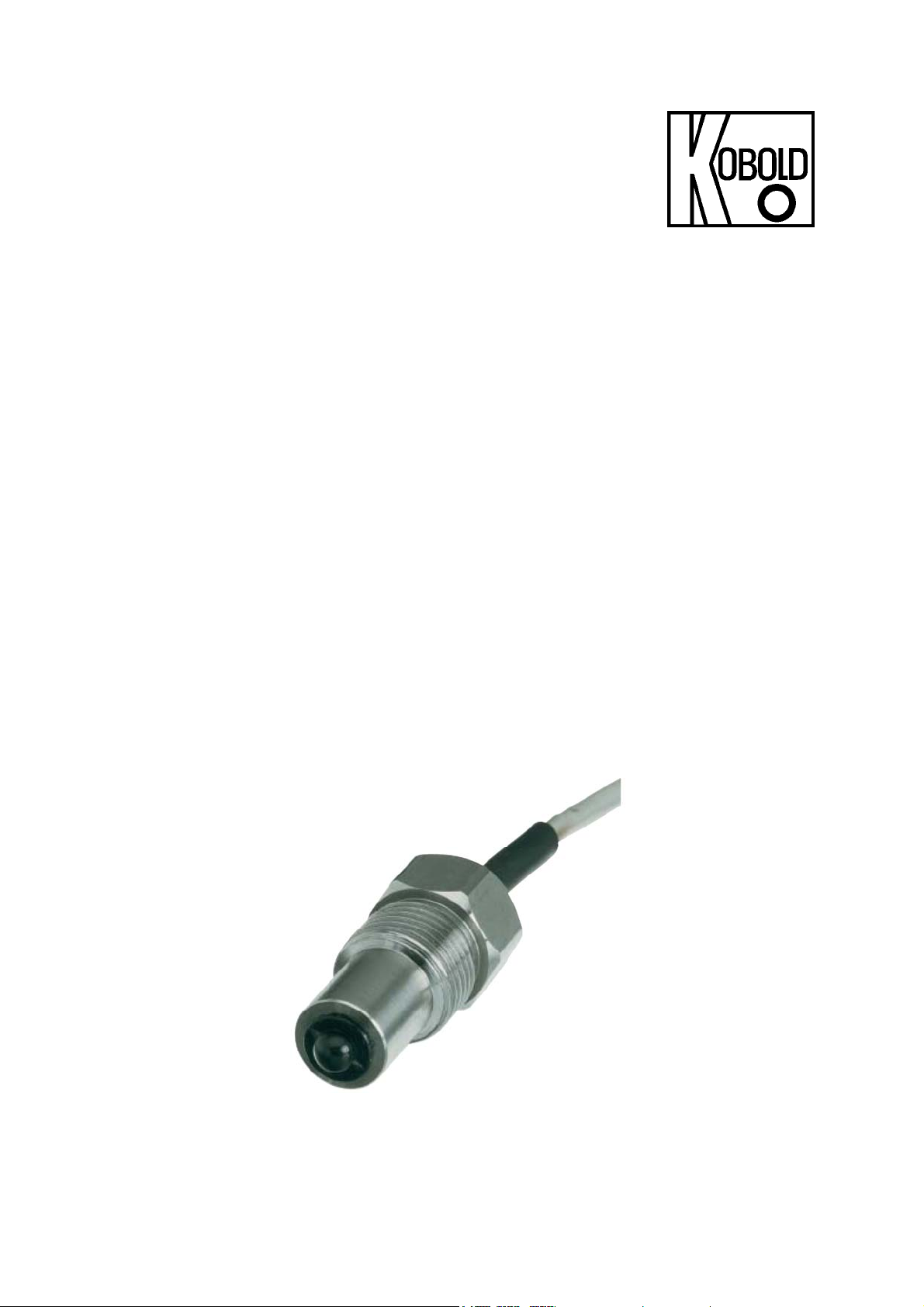
Optical Level Sensor
Model: OPT
Page 2

OPT
1. Contents
1. Contents ........................................................................................................ 2
2. Note .............................................................................................................. 2
3. Instrument Inspection .................................................................................... 3
4. Regulation Use .............................................................................................. 3
5. Operating Principle ........................................................................................ 3
6. Mechanical Connection ................................................................................. 4
6.1. Process Connection M14 with Nut (OPT-..10) ..................................... 4
6.2. Process Connection G ½ (OPT-..22) ................................................... 4
7. Electrical Connection .................................................................................... 5
7.1. General Information ............................................................................. 5
7.2. Terminal Connection Diagrams ........................................................... 5
8. Technical Information .................................................................................... 6
9. Order Codes ................................................................................................. 7
10. Dimensions ................................................................................................... 7
11. Declaration of Conformance ......................................................................... 8
Manufactured and sold by:
Kobold Messring GmbH
Nordring 22-24
D-65719 Hofheim, Germany
Tel.: +49 (0)6192-2990
Fax: +49(0)6192-23398
E-mail: info.de@kobold.com
Internet: www.kobold.com
2. Note
Please read these operating instructions before unpacking and putting the unit
into operation. Follow the instructions precisely as described herein.
The devices are only to be used, maintained and serviced by persons familiar
with these operating instructions and in accordance with local regulations
applying to Health & Safety and prevention of accidents.
When used in machines, the measuring unit should be used only when the
machines fulfil the EWG-machine guidelines.
When using the OEM designs (OPT - 0), the electromagnetic compatibility in the
plant must be demonstrated. The sensors themselves are not subjected to any
testing of this type.
Page 2 OPT K02/0410
Page 3

OPT
3. Instrument Inspection
All Instruments are inspected before shipping and sent out in perfect condition.
Should damage to a device be visible, we recommend a thorough inspection of
the delivery packaging. In case of damage, please inform your parcel service /
forwarding agent immediately, since they are responsible for damages during
transit.
Scope of delivery:
The standard delivery includes:
• Optical Level Sensor model: OPT
• Operating instructions
4. Regulation Use
Any use of the Optical Level Sensor, model: OPT, which exceeds the
manufacturers specification may invalidate its warranty. Therefore any resulting
damage is not the responsibility of the manufacturer. The user assumes all risk
for such usage.
5. Operating Principle
The optical level sensors of model OPT have been developed for monitoring
transparent liquids. Due to the very small dimensions, very slight switching
hysteresis and high repeatability, the instruments are also suited for service in
small vessels. The optical sensor is situated in a robust housing. It comprises a
plastic hollow hemisphere, in which the infrared diode is fitted as a transmitter
and a semiconductor as a receiver. When the sensor is not wetted by liquid, the
infrared light is reflected fully from the surface of the hemisphere to the receiver.
As soon as the sensor is covered with liquid, the refractive index on the boundary
layer changes and most of the light escapes into the liquid. Less light then
reaches the receiver, which allows switching to take place. The level probe
should not be fitted with the sensor pointing downwards, as errors can occur due
to drops of liquid sticking to it.
OPT K02/0410 Page 3
Page 4

OPT
6. Mechanical Connection
Before installation:
Make sure that the maximum operating pressures and temperatures allowed for
this device are not exceeded (see 8. Technical Information).
Avoid mounting the Optical Level Sensor vertically downward from the top of the
container cover. In this position, drops accumulating on the optical sensor can
cause the sensor to report an apparent, false, simulated level (switching point
reached).
Recommended mounting positions:
• On the side wall of the tank
• Vertically upward on the bottom of the tank
6.1. Process Connection M14 with Nut (OPT-..10)
(OPT-..22)
Hole in the bottom of the tank:
∅ 15 mm
The device is sealed with the
supplied O-ring.
6.2. Process
Connection G ½
eal the device in the side of the
S
container with PTFE tape or similar
sealant.
Page 4 OPT K02/0410
Page 5

OPT
7. Electrical Connection
7.1. General Information
Attention! Make sure that the voltage values of your system
correspond with the voltage values of the measuring unit.
Make sure that the supply wires are de-energised.
7.2. Terminal Connection Diagrams
OPT K02/0410 Page 5
Page 6

OPT
8. Technical Information
Operating temperature: -20 to +80 °C
Operating pressure: max. 10 bar
Protection: IP 68
Material:
Housing: OPT-_1_ _: Polypropylene
OPT-_2_ _: St. steel (1.4301)
Sensor: Polysulfone
Cable: Polyurethane 1.5 m, ∅ 4.5 mm
O-ring: OPT-_2_ _: FPM
Hexagon nut: OPT-_ _10: Polyamide
Flat gasket: OPT-_ _10: FPM
Electrical data
Repeatability: ±1 mm
Hysteresis: ±1 mm
Response time: 50 µsec (with rising level)
1 sec (with falling level)
depending on viscosity
OPT-0 (OEM-version, without CE-marking)
Power supply: 5-12 VDC ± 5 %
Current input: 15 mA typ. at V
Output: NPN, open collector,
function N/O contact (WET on)
Current output: 10 mA max. at 25 °C
3 mA max. at 80 °C
OPT-4
Power supply: 24 VDC ± 15 %
Current input: 17 mA typ. at. 24 V
Output: PNP, Open Collector,
function N/O contact (WET on)
Current output: 200 mA, short-circuit-proof
OPT-5
Power supply: 24 VDC ± 15 %
Current input: 17 mA typ. at 24 V
Output: NPN, Open Collector,
function N/C contact (DRY on)
Current output: 200 mA, short-circuit-proof
OPT-6
Power supply: 24 VDC ± 15 %
Current input: 17 mA typ. at 24 VDC (without load)
Output: NPN, Open Collector,
function N/O contact (WET on)
Current output: 20 mA max., not short-circuit-proof
(without load)
DC
(without load)
DC
(without load)
DC
Page 6 OPT K02/0410
Page 7

OPT
9. Order Codes
Example: OPT-0 1 10
Model Version Housing material Connection female thread
0 = 5-12 V
OPT-
MSR-010
4 = 24 V
5 = 24 V
6 = 24 V
10. Dimensions
, NPN, OEM (without CE)
DC
± 15 %, PNP
DC
± 15 %, NPN
DC
± 15 %, NPN
DC
Contact protection relay for OPT-4 and OPT-5, 230 V
1 = Polypropylene
2 = Stainless steel
10 = M14 with nut
22 = G ½
N4 = ½ NPT
AC
OPT K02/0410 Page 7
Page 8

OPT
11. Declaration of Conformance
We, KOBOLD Messring GmbH, Hofheim-Ts, Germany, declare under our sole
responsibility that the product:
Optical Level Sensor model: OPT –4..., OPT –5... and OPT-6
to which this declaration relates is in conformity with the standards noted below:
EN 61000-6-2 (2002-08)
Electromagnetic compatibility (EMC) - Basic specification: Noise immunity
a.) EN 61000-4-4 (2002-07) Susceptibility to fast transients
(IEC 1000-4, BURST
b.) EN 61000-4-2 (2001-12) Susceptibility to the discharge of
electrostatic electricity
EN 61000-6-3 (2002-08)
Electromagnetic compatibility (EMC) – Basic specification: Emitted interference
for living quarters
EN 61010-1 (2002-08)
Safety assurance for electrical measuring, control- and laboratory instruments
Also in conformance with the specifications in the following EEC directives:
2004/108/EC Electromagnetic compatibility (EMC)
Hofheim, 14. March 2006
H. Peters M. Wenzel
General Manager Proxy Holder
Page 8 OPT K02/0410
 Loading...