

Page 1
KOBOLD OME FLOWMETER
User Instructions
USA
1801 Parkway View Drive
Pittsburgh, PA 15205
PH 412-788-2830
www.koboldusa.com
Canada
9A Aviation
Point Claire, QC H9R 4Z2
PH 514-428-8090
OME_manual_10-16-2002
Page 2

Table of Contents
1.0 General .........................................................................................................1
2.0 Specifications .............................................................................................. 1
3.0 Installation instructions................................................................................. 4
4.0 Maintenance ................................................................................................ 5
5.0 Arrival of Damaged Equipment ................................................................. 5
6.0 Need Help With Your OME ......................................................................... 5
List of Diagrams
Diagram 2.3 Pressure Loss Data ........................................................... 2
Diagram 2.4 Dimensions ......................................................................... 3
Diagram 2.5 Electrical connections ......................................................... 3
List of Tables
Table 2.1 Technical Data ........................................................................1
Table 2.2 Model Specific Data .............................................................. 2
Page 3
OME
KOBOLD OME FLOWMETER
User Instructions
CAUTION: For safety reasons, please read the cautionary information located at
the end of the manual, before attempting installation.
1.0 General
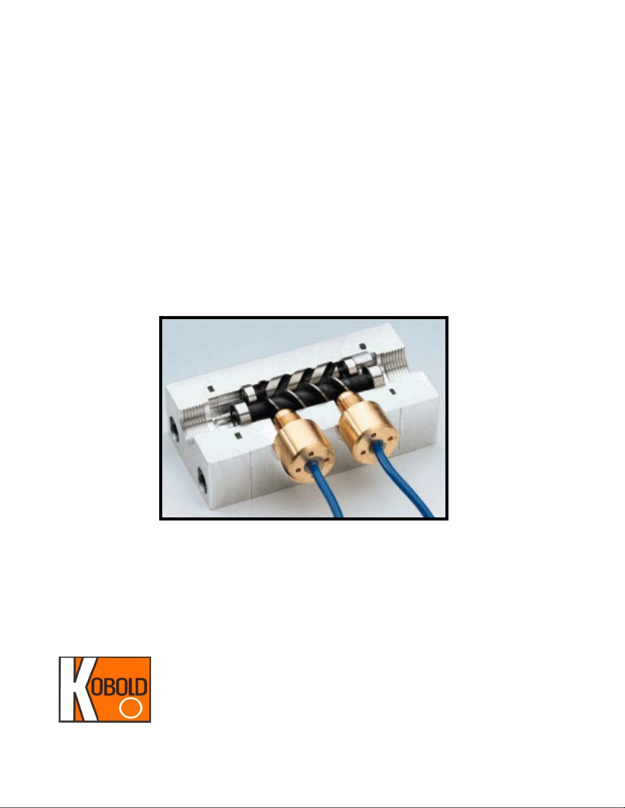
The KOBOLD OME helical gear positive displacement flowmeter is designed to measure
the volume flow rate of clean, non-abrasive, lubricating liquids whose viscosities lie in the
range of 1 to 5000 cSt. The measuring principle of this fowmeter can be described as follows:.
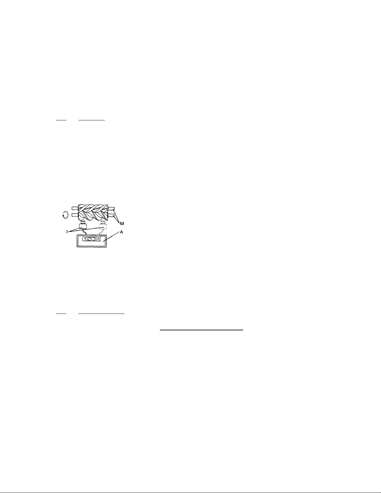
1. As the fluid to be measured is forced through the flowmeter by system
pressure, it causes the helical spindles (M) to rotate.
2. Each rotation of the spindle equates to an exact volume
of liquid which has passed through the flowmeter.
3. Permanent magnets are imbedded in the spindles; as
the spindle rotates, these magnets pass by a magnetic
pickup.
4. The pickup (I) generates a voltage pulse each time a magnet passes by.
These pulses can then be transmitted to a data acquisition device (A) where
the pulse frequency is translated into a rate of flow.
The helical gear design provides quiet operation, low pressure loss and few pulsations.
2.0 Specifications
Table 2.1; Technical Data
Operating Principle: Positive Displacement, helical gears
Dimensions: See Diagram 2.6
Range: 0.05 to 26.4 GPM
Accuracy: ± 0.3% of flow rate
Temperature range: -20° F to 212° F
Maximum operating Pressure
NPT: 580 PSIG
150 pound flange: 215 PSIG
300 pound flange: 560 PSIG
Max. differential: 75 PSIG
Filtration requirements: 300 micron (50 mesh) max.
FM Rev 10/02
Page 4

OME 2
Wetted parts:
Housing ...... Aluminum Gears ...... Nitrided steel
Bearings ...... Chrome steel Seals ...... FKM
Flanges ...... Carbon Steel
Sensor Data:
Power Supply
PNP: 10-30 VDC 50 mA Max.
NAMUR: 8.2 VDC ±0.1 VDC
Frequency Range: 0 to 5000 Hz.
Table 2.2; Model Specific Data
Table 2.23; Pressure Loss Diagram
FM Rev 10/02
Page 5

3OME
1
4
3
1
3
Diagram 2.4,Dimensions
Diagram 2.5 Electrical Connections
PNP Sensor NAMUR Sensor
+ V Supply
- V
Supply
1 = Brown
3 = Blue
4 = Black
Z
FM Rev 10/02
+ V supply (+8.2 VDC)
- V (Ri=1k Ohm)
Page 6

OME 4
3.0 Installation Instructions
CAUTION: For safety reasons, please read the cautionary information located at
the end of the manual, before attempting installation.
The following practices and guidelines should be applied when installing your flow
sensor. Proper installation will ensure the highest possible degree of measuring
accuracy and will maximize service life.
Orientation in the piping system: The flow sensor can be mounted in any orientation in
the piping system. There are no requirements for minimum straight piping runs at the
inlet or outlet of this unit.
Piping Alignment: The piping into and out of the flow sensor must be properly plumbed
and aligned such that no torsional or tensile stresses are placed on the sensor after it is
fastened into place.
Piping Supports: The piping at the inlet and outlet of the flow sensor must be rigidly
supported in order to prevent excessive piping vibration.
Flow Direction: The unit is capable of bi-directional flow. However; the sensor should be
mounted in the system such that during normal operation, flow moves in the direction of
the solid arrow on the nameplate.
System Pressure:The flow sensor requires a minimum back-pressure of 1.5 PSIG at
the sensor outlet. Under no circumstances should fluids be allowed the free flow
out of the sensor outlet. This will result in excessive bearing wear and reduce the
bearing service life.
Filtration Requirements: Solid particulates in the flow medium can result in damage to
the internal gears and failure of the sensor. Filtration of solids with a filter equivalent to
#50 mesh (300 micron) is required.
Over Pressure Protection: If the flow sensor becomes blocked or seized, system flow
will be stopped completely. This could cause pressure surges in the system resulting in
FM Rev 10/02
Page 7

5OME
damage to system components. For this reason it is recommended that a pressure relief
valve be installed upstream of the flowmeter.
4.0 Maintenance
Due to its construction, a positive displacement flowmeter, such as the OME, is nearly
maintenance-free.
Please note the filtration requirements in the specification section. Make sure the filter is
kept in proper functioning condition. The frequency of filter replacement and maintenance will depend on the level of cleanliness of the metered luquid.
The only wear component in the OME are the gear teeth, which will wear in time. The
rate of wear depends on the duration of operation and the abrasion/lubrication properties
of the measured liquid. It is recommended that a periodic check of the meter’s calibration
be conducted on a yearly basis - using a bucket, stopwatch and a reliable, calibrated
weigh scale.
5.0 Arrival of Damaged Equipment
Your instrument was inspected prior to shipment and found to be defect-free. If damage
is visible on the unit, we advise that you carefully inspect the packing in which it was
delivered. If damage is visible, notify your local carrier at once, since the carrier is liable
for a replacement under these circumstances. If your claim is refused, please contact
KOBOLD Instruments for further advisement.
6.0 Need help with your OME?
Call one of our friendly engineers at 412-788-2830.
FM Rev 10/02
Page 8

7OME
Caution
PLEASE READ THE FOLLOWING GENERAL FLOW METER/ MONITOR
WARNINGS BEFORE ATTEMPTING INSTALLATION OF YOUR NEW
DEVICE. FAILURE TO HEED THE INFORMATION HEREIN MAY
RESULT IN EQUIPMENT FAILURE AND POSSIBLE SUBSEQUENT
PERSONAL INJURY.
FM Rev 10/02
Page 9

OME 8
• User's Responsibility for Safety: KOBOLD manufactures a wide range of
process sensors and technologies. While each of these technologies are
designed to operate in a wide variety of applications, it is the user's
responsibility to select a technology that is appropriate for the application,
to install it per these installation instructions, to perform tests of the
installed system, and to maintain all components. The failure to do so could
result in property damage or serious injury.
• Proper Installation and Handling: Use a proper sealant with all
installations. Never overtighten fittings. Always check for leaks prior to
system start-up.
• Wiring and Electrical: Depending on the model, a supply voltage of
VDC (10-30 VDC)
or
8.2 VDC (NAMUR)
is used to power the OME. The
24
sensor systems should never exceed this rating. Electrical wiring of the
sensor should be performed in accordance with all applicable national,
state, and local codes.
• Temperature and Pressure: The OME is designed for use in application
temperatures from -20 to 212°F, and for use at pressures up to 580 PSIG
(215 PSIG with 150# flange, 560 PSIG with 300# flange). Operation
outside these limitations will cause damage to the unit and possible
personnal injury.
• Material Compatibility: Make sure that the wetted parts listed in Table 2.1
are chemically compatible with the application liquids. While the electronics
cable connections are rated NEMA 4 when installed properly,they are not
designed to be immersed. The OME should be mounted in such a way that
the housing does not normally come into continuous contact with fluid.
• Flammable, Explosive and Hazardous Applications: The OME is not of
an explosion proof design and should not be used in areas where an
explosion proof design is required.
• Make a Fail-Safe System: Design a fail-safe system that accommodates
the possibility of switch or power failure as well as operator error. In critical
applications, KOBOLD recommends the use of redundant backup systems
and alarms in addition to the primary system.
FM Rev 10/02
 Loading...